
DSP 15 - Pressure sprayer EINHELL - Free user manual and instructions
Find the device manual for free DSP 15 EINHELL in PDF.

| Product type | Pressure sprayer |
| Brand | Einhell |
| Model | DSP 15 |
| Tank capacity | 15 liters |
| Pump type | Piston pump |
| Maximum working pressure | 4 bar |
| Stroke volume | 80 cm³ |
| Tank material | UV-stabilized plastic |
| Recommended use | Arboriculture, horticulture, viticulture, nurseries |
| Included nozzles | Conical jet nozzle and flat jet nozzle |
| Included accessories | Funnel strainer, key |
| Maintenance | Cleaning after each use, check of seals and filters |
| Storage | Protected from frost and direct sunlight |
| Warranty | 24 months |
| Estimated weight | 3.5 kg |
| Prohibitions | Acids, liquids >40°C, flammable (flash point <55°C) |
| Spare parts | Use original parts |
| Safety | Wear protective clothing, avoid any contact |
Frequently Asked Questions - DSP 15 EINHELL
User questions about DSP 15 EINHELL
0 question about this device. Answer the ones you know or ask your own.
Ask a new question about this device
Download the instructions for your Pressure sprayer in PDF format for free! Find your manual DSP 15 - EINHELL and take your electronic device back in hand. On this page are published all the documents necessary for the use of your device. DSP 15 by EINHELL.
USER MANUAL DSP 15 EINHELL
natural_image
Close-up of a mechanical assembly with labeled parts (A, B, C) and a tool handle (no readable text or symbols)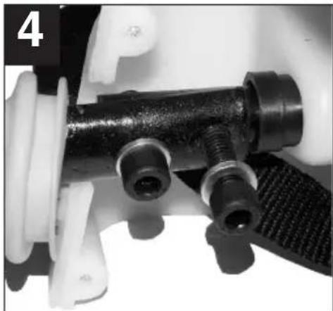
natural_image
Close-up of a mechanical component with black plastic fittings and threaded connectors (no visible text or symbols)D
Vessel capacity: 15 liters
Pump system: piston pump
Operating pressure: max. 4 bar
Stroke volume: 80 cm3
The Einhell pressure sprayer DSP 15 can be used with all approved pesticides and comparable liquids in fruit farming, horticulture, viniculture, forestry and tree nurseries.
The use of caustic and acidic preparations with the pressure sprayer is prohibited.
It is imperative to observe all pertinent accident prevention regulations and other generally applicable rules of safety.
1
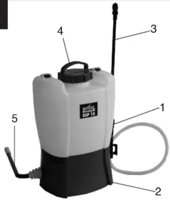
1 pressure sprayer vessel
2 cover
3 spray tube complete with nozzle and pistol grip
4 vessel cap
5 pump lever

Safety information and warnings
- Do not use the pressure sprayer when people (particularly children) or animals are in the direct vicinity. The user is responsible for any harm caused to third parties and for any damage caused to their property.
- Whenever you use pesticide equipment and pesticides of any kind it is imperative to take special notice of the safety measures stipulated by the pesticide producer and the personal safety measures (protective clothing, breathing mask and safety goggles) required for the user.
● Each time after using the pressure sprayer, and particularly at the end of the spraying season, it is imperative to rinse out and clean the vessel with special care, along with all other parts of the sprayer which come into contact with the pesticide. - Pesticide residues may result in corrosion and hence damage to the sprayer.
● Pay special attention to wearing parts such as nozzles, filters and seals.
● Never use hard objects to clean nozzles. - If any of the mix is left over after treating plants or shrubs, dilute the remaining liquid by approx. 1:10 with water and distribute it over the treated area.
- Replace damaged parts without delay. Use only original replacement parts.
- Before carrying out any maintenance work or repairs - including to the hose and shut-off valve - make sure that the sprayer is not under pressure.
- When unscrewing the spray tube, keep its end pointed away from you.
-
For safety reasons it is prohibited to use the back-sprayer for:
-
caustic liquids (e.g. disinfectants and impregnating media),
- liquids hotter than 40°C,
- combustible liquids with a flash point below 55^ C.
2. Assembly
● The sprayer comes fully assembled except for the hand lever.
● The spray tube also comes fully assembly and has to be tightly screwed to the handle with the union nut.
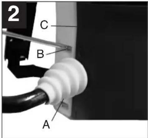
- Remove the cover (C) by unscrewing the six recessed head screws (B) at the rear (Figure 2).
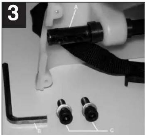
● Unscrew the two hexagon socket-head screws (C) from the pump axle (A) (Figure 3).
● Fasten the pump lever to the pump axle with the screws (C) (Figure 4). The pump lever has to point forward. Use the wrench (B).
- Insert the collar in the half-housing.
- Screw the cover (C) back in position (Figure 2). Make sure that the collar and - on the other side - the spray hose are correctly seated in the bushing and are not squashed between the two plastic parts.
natural_image
Close-up of mechanical components including a black tool, black connectors, and a white component with a curved handle (no visible text or symbols)
natural_image
Close-up of a mechanical component with threaded connectors and a black cylindrical body (no visible text or symbols)GB
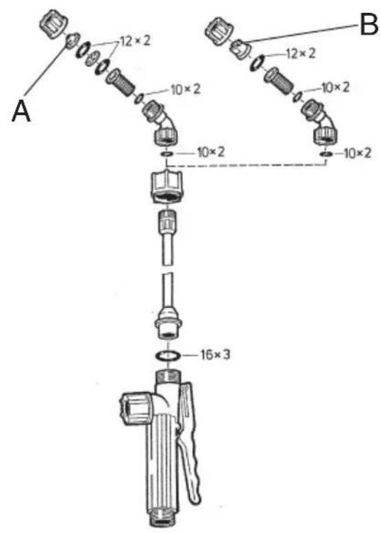
Nozzles with a cone spray pattern (A) are best for treating shrubs, trees etc. (three-dimensional distribution). Nozzles with a flat spray pattern (B) are recommended for treating surfaces (two-dimensional distribution).
● The spray tube is fastened in place by tightening the union nut on the pistol grip.
- Spraying pressure can be adjusted in the range from approximately 1 to 4 bar (see „Pressure adjustment“) in order to control the distribution rate and droplet size.
3. Pressure adjustment
The pressure setting has to be adjusted before filling in the pesticide etc. To do so, twist the adjusting cap (A) over the markings on the pressure tank.

4. Spraying rates
● Make up the mix according to the instructions issued by the manufacturer of the preparation in question. Only make up an amount sufficient to meet your actual needs.
Recommended spraying rates for plant protection purposes:
Ground vegetation 0.3-0.5 l for 10 m2
Low shrubs 1.0-1.5 l for 10 m2
Trellis tress, spindle trees 0.5-1.0 l per piece
Large bushes 2.0 l per piece
Old, free-standing trees 3.0-5.0 l per piece
- For liquid pesticides, fill the vessel 1/4 with water and add the pesticide pre-mixed with water. Top up with the required amount of water and mix thoroughly.
- When using mixes of vegetable preparations, make sure that the liquid is filtered before you fill it in.

Be sure to observe the safety instructions issued by the manufacturer of the preparation in question!
5. Making up pesticide mixes
● Always make up your pesticide mixes outdoors, never inside the home, stalls or storage rooms for food and feedstuff.
● Powdery pesticides should be thoroughly pre-mixed in a separate container before you fill them into the pressure sprayer through the filling sieve. Keep re-stirring the mix.
6. Filling the sprayer
● Always use the supplied sieve funnel when filling the sprayer and supervise the entire filling operation.
● Avoid direct connections between the water filling hose and the mix in the vessel.
- It is absolutely imperative not to allow any of the mix to be drawn back into the water mains.
- When filling in the pesticide etc., make sure that it does not come into contact with the surroundings, the ecosystem and the water mains.
- Filling the vessel from the public water mains with a hose is only permitted if a non-return valve is installed upstream from the water connection.
- Do not allow the vessel to overflow. Guard against polluting public waters, rain pipes and sewers.
7. Spraying
● Operate the lever quickly to prime the pump and
- press on the pistol trigger to open the shut-off valve and allow spray to come out through the nozzle.
● The spray will be cut off immediately when you let go of the pistol trigger.
8. Proper maintenance and care
- Your back-sprayer requires practically no maintenance.
- If you ever have difficulty closing or opening the vessel cap, apply a little oil to the inserted rubber sealing ring.
Proper maintenance also entails: - checking the liquid vessel,
- checking all the hose lines and their couplings,
- cleaning all the filter inserts and checking them for damage.
● An additional sieve is fitted to the inlet to the pressure tank and cylinder compartment in order to protect the piston, cylinder and piston collars from contaminated spraying mix. This sieve can be cleaned by vigorous swilling out when you have finished spraying.
9. Storage
Although the vessel is made of UV-stabilized material we still recommend that you protect the sprayer from direct sunshine by storing it in a dry room that is inaccessible to children and animals. When sub-zero temperatures threaten it is imperative to remove all liquid from the vessel, the pressure tank and the lines.
natural_image
Close-up of mechanical components including a black tool, black connectors, and a white component with a curved handle (no visible text or symbols)
natural_image
Close-up of a mechanical component with threaded connectors and a black cylindrical body (no visible text or symbols)F
natural_image
Close-up of mechanical components including a black tool, black connectors, and a white component with a curved handle (no visible text or symbols)
natural_image
Close-up of a mechanical component with threaded connectors and a black cylindrical body (no visible text or symbols)natural_image
Close-up of mechanical components including a black cable, connector, and two labeled parts (A, B, C) on a surface (no text or symbols beyond labels)
natural_image
Close-up of a mechanical component with threaded connectors and a black plastic fitting (no visible text or symbols)natural_image
Close-up of mechanical components including a black cable, threaded rod, and two labeled connectors (B and C), with no visible text or symbols.
natural_image
Close-up of a mechanical component with threaded connectors and a black cylindrical body (no visible text or symbols)natural_image
Close-up of mechanical components including a black cable, connector, and two labeled parts (A, B, C) on a surface (no text or symbols beyond labels)
natural_image
Close-up of a mechanical component with threaded connectors and a black cylindrical body (no visible text or symbols)S
natural_image
Close-up of a mechanical assembly with labeled parts (A, B, C) and a tool handle (no readable text or symbols beyond labels)
natural_image
Close-up of a mechanical component with threaded connectors and a black cylindrical body (no visible text or symbols)FIN
natural_image
Close-up of mechanical components including a black cable, connector, and two labeled parts (A, B, C) on a surface (no text or symbols beyond labels)
natural_image
Close-up of a mechanical component with threaded connectors and a black plastic fitting (no visible text or symbols)GR
natural_image
Close-up of mechanical components including a black cable, connector, and two labeled parts (A, B, C) on a surface (no text or symbols beyond labels)
natural_image
Close-up of a mechanical component with threaded connectors and a black cylindrical body (no visible text or symbols)natural_image
Close-up of mechanical components including a black cable, threaded rod, and two labeled connectors (B and C), with no visible text or symbols.
natural_image
Close-up of a mechanical component with threaded connectors and a black cylindrical body (no visible text or symbols)natural_image
Close-up of mechanical components including a black cable, connector, and two labeled parts (A, B, C) on a surface (no text or symbols beyond labels)
natural_image
Close-up of a mechanical component with threaded connectors and a black cylindrical body (no visible text or symbols)The guarantee period begins on the sales date and is valid for 2 years.
Responsibility is assumed for faulty construction or material or functional defects.
Any necessary replacement parts an necessary repair work are free of charge.
We do not assume responsibility for consequential damage.
Your customer service partner
F GARANTIE EINHELL
⑤ EINHELL GARANTIBEVIS
DK EINHELL GARANTIBEVIS
Eschenstraße 6 · D-94405 Landau/Isar (Germany)
Technical changes subject to change
Brook House, Brookway
North Chesire Trading Estate
Prenton, Wirral, Chesire
CH 43 3DS
Tel. 0151 6084802, Fax 0151 6086339
S.C. A Ap. 9 Sector 1
RO 75 121 Bucharest
Tel. 01 4104800, Fax 01 4103568
©z Marimex cz
Libusská 264
CZ-14200 Praha 4
Tel. 02 4727740, Fax 02 61711056