HX-WA30 - Heating Reer - Free user manual and instructions
Find the device manual for free HX-WA30 Reer in PDF.


User questions about HX-WA30 Reer
0 question about this device. Answer the ones you know or ask your own.
Ask a new question about this device
Download the instructions for your Heating in PDF format for free! Find your manual HX-WA30 - Reer and take your electronic device back in hand. On this page are published all the documents necessary for the use of your device. HX-WA30 by Reer.
USER MANUAL HX-WA30 Reer
natural_image
Hand holding a white air conditioner unit with a handle, no visible text or symbols
natural_image
Close-up of a mechanical component with directional arrows indicating rotation or movement (no text or symbols visible)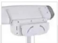
natural_image
Close-up of a white surveillance camera with mounted lens and control panel (no visible text or symbols)GB 2in1 FeelWell - changing table heater Instructions for use
ES radiador térmico de cambiador - 2en 1 FeelWell Manual de uso
IT radiatore per fasciatoio - 2in1 FeelWell
Istruzioni per l'uso
FR 2en1 FeelWell - pour table à langer
Notice d'utilisation
NL 2in1 FeelWell - Warmtelamp voor luiertafel
Gebruiksaanwijzing
DK 2in1 FeelWell - puslebord-varmestråler Brugsvejledning
GR 2σε1 FeelWell - Θερμοπομπός αλλαξιέρας
ΟΔΗΓΙΕΣ
PL 2w1 FeelWell - Promiennik ciepła do przewijaka dla niemowląt Instrukcja obsługi
CZ 2v1 FeelWell - tepe Iný zářič na přebalovací stůl
Návod k použití
natural_image
Diagram of a four-pole mechanical device with labeled section A1 (no text or symbols on the device itself)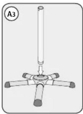
natural_image
Simple line drawing of a four-petal mechanical component with a cylindrical shaft and base (no text or symbols)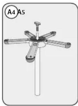
natural_image
Mechanical component diagram with five arms and a central shaft, labeled A4 and A5 (no text or symbols on the diagram itself)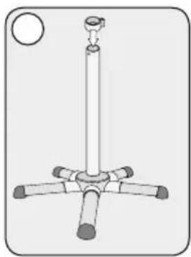
natural_image
Simple line drawing of a vertical pole with four arms and a circular top, no text or symbols present.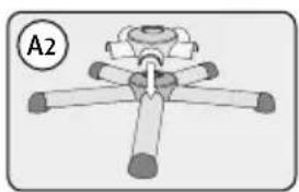
natural_image
Diagram of a mechanical or electrical component with four arms and a central hub, labeled A2 (no text or symbols on the diagram itself)
text_image
Diagram showing a mechanical assembly with a spring and pin, highlighting a specific component with a red circle.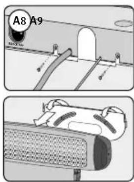
text_image
A8 A9 M1000000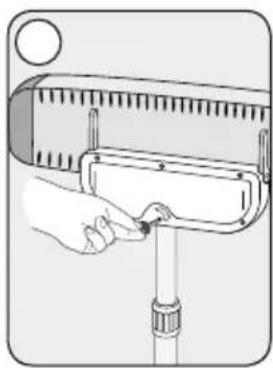
natural_image
Illustration of a hand using a tool to adjust or install a mechanical component (no text or symbols visible)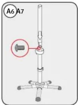
text_image
A6 A7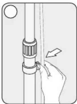
natural_image
Illustration of a hand adjusting a mechanical component with an arrow indicating direction (no text or symbols)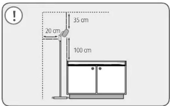
text_image
35 cm 20 cm 100 cm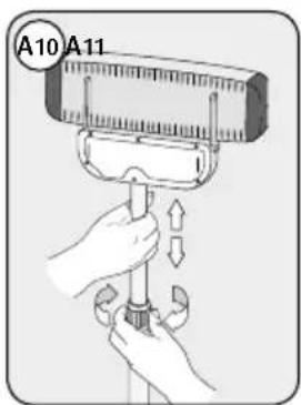
text_image
A10 A11GB Wall-mounted assembly
ES Montaje mural
natural_image
Diagram of a car air conditioner unit with labeled parts B3 and B4 (no text or symbols on the device itself)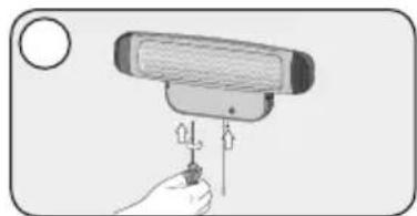
natural_image
Illustration of a hand holding a device with a screwdriver inserted (no text or symbols visible)| Inhaltsverzeichnis | Allgemeine Sicherheitshinweise. . . . . . . . . . . . . . . . . . . . . . . . . . . . . . . . . . . . . . . . . . . . . . . . . . . . . . . . . . . . . . . . . . . . . . . . . . . . . . . . . . . . . . . . . . . . . . . . . . . . . | Sicherheitshinweise bei Wandmontage. . . . . . . . . . . . . . . . . . . . . . . . . . . . . . . . . . . . . . . . . . . . . . . . . . . . . . . . . . . . . . . . . . . . . . . . . . . . . . . . . . . . . . . . . . . . . . . . . . . | |
| Technische Daten. . . . . . . . . . . . . . . . . . . . . . . . . . . . . . . . . . . . . . . . . . . . . . . . . . . . . . . . . . . . . . . . . . . . . . . . . . . . . . . . . . . . . . . . . . . . . . . . . . . | Inbetriebnahme. . . . . . . . . . . . . . . . . . . . . . . . . . . . . . . . . . . . . . . . . . . . . . . . . . . . . . . . . . . . . . . . . . . . . . . . . . . . . . . . . . . . . . . . . . . . . . . . . . . | ||
| Lieferumfang und Teilebezeichnung. . . . . . . . . . . . . . . . . . . . . . . . . . . . . . . . . . . . . . . . . . . . . . . . . . . . . . . . . . . . . . . . . . . . . . . . . . . . . . . . . . . . . . . . . . . . . . . . . . . Montage. . . . . . . . . . . . . . . . . . . . . . . . . . . . . . . . . . . . . . . . . . . . . . . . . . . . . . . . . . . . . . . . . . . . . . . . . . . . . . . . . . . . . . . . . . . . . . . . . . | Reinigung & Wartung. . . . . . . . . . . . . . . . . . . . . . . . . . . . . . . . . . . . . . . . . . . . . . . . . . . . . . . . . . . . . . . . . . . . . . . . . . . . . . . . . . . . . . . . . . . . . . . . . . . 09 Garantie. . . . . . . . . . . . . . . . . . . . . . . . . . . . . . . . . . . . . . . . . . . . . . . . . . . . . . . . . . . . . . . . . . . . . . . . . . . . . . . . . . . . . . . . . . . . . . . . . . . | ||
| Contents | General safety instructions. . . . . . . . . . . . . . . . . . . . . . Technical specification. . . . . Items delivered, part description. 11 Assembly. 12 | Safety instructions for wall installation. 12 Putting into operation. 13 Cleaning, maintenance. 14 Warranty. 14 | |
| Índice | Indicaciones generales de seguridad. 15 Datos técnicos. 16 Volumen de suministro, denominación de las piezas. 16 Montaje. 17 | Indicaciones de seguridad para montaje mural. 17 Puesta en funcionamiento. 18 Limpieza, mantenimiento. 19 Garantia. 19 | |
| Indice | Avvertenze. 20 Dati tecnici. 21 Contenuto della confezione, descrizione componenti. 21 Montaggio. 22 | Avvertenze di sicurezza in caso di montaggio a parete. 22 Messa in funzione. 23 Pulizia, manutenzione. 24 Garanzia. 24 | |
| Table des matières | Consignes générales de sécurité. 25 Caractéristiques techniques. 26 Contenu de la livraison, désignation des composants. 26 Montage. 27 | Consignes de sécurité pour fixation murale. 27 Mise en service. 28 Nettoyage, entretien. 29 Garantie. 29 | |
| Inhoudsopgave | Algemene veiligheidsaanwijzingen. 30 Technische gegevens. 31 Omvang van de levering, onderdelenomschrijving. 31 Montage. 32 | Veiligheidsaanwijzingen bij de montage aan de wand. 32 Inbedrijfstelling. 33 Reiniging, onderhoud. 34 Waarborg. 34 | |
| Indhold | Generelle sikkerhedshenvisninger. 35 Tekniske data. 36 Delebetegnelse, komponentbetegnelse. 36 Montering. 37 | Sikkerhedshenanvisninger ved vægmontering. 37 Ibrugtagning. 38 Rengering, vedligeholdelse. 39 Garanti. 39 | |
| Півакає петріехомеюв | Гевикєс упобейєис аофалівіс. 40 Техикá δεδομένα. 41 Парадотеза поостітта, Характніраюс мерών. 41 Συναρμολόγηση. 42 | Упобейєис аофалівіс катá тн оуварμολόγηση σε τοίχο. 42 Θέση σε λειτουργία. 43 Kaθαρισμός, αυντήρηση. 44 Egyúηση. 44 | |
| Spis treści | Ogólne przepisy bezpieczeństwa. 45 Dane techniczne. 46 Zakres dostawy, nazwa podzespolu. 46 Montaž. 47 | Przepisy bezpieczeństwa w przypadku montażu na ścianie. 47 Uruchomlenie. 48 Czyszczenie, konserwacja. 49 Garantie. 49 | |
| Obsah | Všeobecné bezpečnostní pokyny. 50 Technické údaje. 51 Obsah dodávky, popis částí. 51 Montaž. 52 | Montaž tepelného záříče na stěnu. 52 Uvedení do provozu. 53 Čištění, údržba. 54 Záruka. 54 | |
natural_image
3D mechanical component diagram with labeled section A and multiplier 1 x (no text or symbols on the object itself)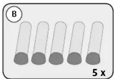
text_image
B 5 x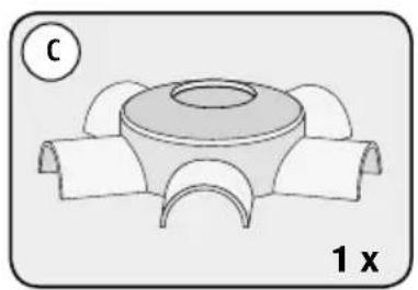
natural_image
Diagram of a mechanical component with a central circular feature and four curved arms, labeled '1 x' (no text or symbols on the diagram itself)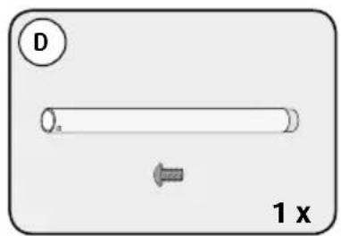
text_image
D 1 x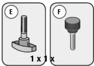
natural_image
Two mechanical component diagrams labeled E and F, showing different sizes (1x1x) with no visible text or symbols beyond labels.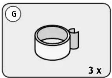
natural_image
Simple line drawing of a cylindrical object with a handle, labeled 'G' and '3 x' (no text or symbols on the object itself)
text_image
H 1 x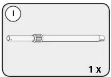
natural_image
Simple line drawing of a cylindrical object with a side protrusion, labeled '1 x' (no text or symbols on the object itself)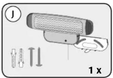
text_image
J 1 xTeilebezeichnung
flowchart
graph LR
    A["1: 230 V power source"] --> B["2: Sensor connected to a cable"]
    B --> C["ON 400 W power switch"]
    C --> D["2: ON 800 W power switch"]
    D --> E["OFF"]
natural_image
Symbol of a trash bin crossed with no text or numbers, representing environmental protection (no text present)We are pleased that you have chosen this product and would like to thank you the trust you are showing in us. To enjoy the changing table heater to the full, we would ask you to read the following instructions carefully, store this instruction manual in a safe place and pass it on to the relevant user.
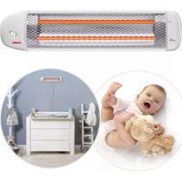
The changing lable heater generates comfortable instant heat in the area around changing lables. It can also be used to warm up bathrooms, hobby rooms, entrance halls, protected patios and balconies quickly. The radiant heat ensure that the surrounding space warms up economically within a few seconds.
Please take a few minutes to read the safety instructions carefully and in full. The instructions in the manual must be followed to avoid damaging the changing table heater. At worst, the unit may constitute a safety or accident hazard for your child, yourself or others.
General safety instructions:
! The unit must only be used for the purposes described herein. Improper use may result in the loss of any and all claims under warranty.
! Check that the information on the nameplate corresponds with the mains voltage in your area.
! The unit must not be used if it shows any sign of a fault.
! If the unit is used as a changing table heater, it must never be used without supervision.
! The maximum exposure time must not exceed 15 minutes.
! A minimum distance of 100 cm between the heater and the table must be observed at all times.
! Keep the supply line away from all hot equipment components, as well as other electrical appliances.
! Avoid additional heat radiation, such as sunlight or other sources of radiation, as this can cause your baby's body temperature to rise.
! The heater must not be used, if a child has a temperature, as this may cause overheating.
! Do not touch the unit when it is in operation.
! The equipment must be connected directly to a power outlet. Do not connect the equipment to units such as a timer, remote control unit etc., as this constitutes a fire hazard.
! The unit remains hot even after it is switched off. Do not cover the changing table heater! Fire hazard.
! Remove all packaging and any surplus components before first use to prevent your child being injured or choking.
! Use the unit only out of the reach of children. Secure the power lead and ensure that it cannot be accidentally pulled out causing the unit to fall on the floor.
! This equipment is not intended for use by persons (including children) with reduced physical, sensory or mental capabilities, or lack of experience or knowledge, unless they are supervised whilst using it or have been shown how to use it correctly by a person responsible for their safety.
! Do not use the equipment if it or its power lead is damaged.
! Repairs must be carried out by qualified and skilled personnel only. Improper repairs may pose considerable risks to the user – this includes changing the power lead.
Technical specification
- rated voltage: 230 V AC
• output: 400 / 800 W - mounting style: Power lead
- protection class: 1
- integrated switch-off function if tilted (tilt angle: 25^ )
- lead length: 185 cm (incl. safety plug)
- heat radiation and temperature distribution tested in accordance with the medical product standard (IEC601-2-21)
Items delivered
natural_image
3D mechanical component diagram with labeled section A and multiplier 1 x (no text or symbols on the object itself)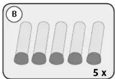
text_image
B 5 x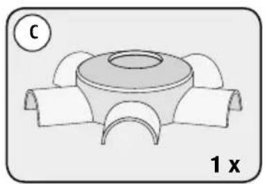
natural_image
Technical diagram of a mechanical component with three curved arms and a central circular feature, labeled '1 x' (no text or symbols beyond labels)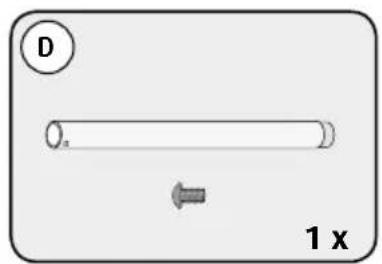
text_image
D 1 x
text_image
E 1 x 1 x F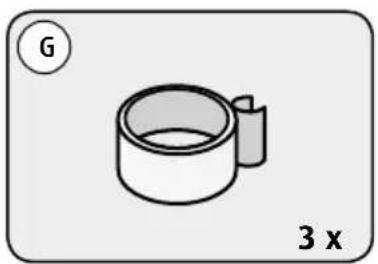
natural_image
Simple line drawing of a cylindrical object with a handle, labeled 'G' and '3 x' (no text or symbols on the object itself)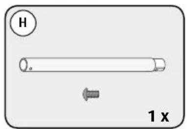
text_image
H 1 x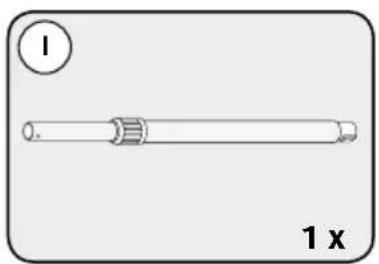
natural_image
Simple line drawing of a cylindrical object with a side protrusion, labeled '1 x' (no text or symbols on the object itself)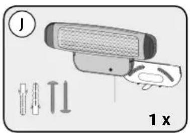
text_image
J 1 xPart description
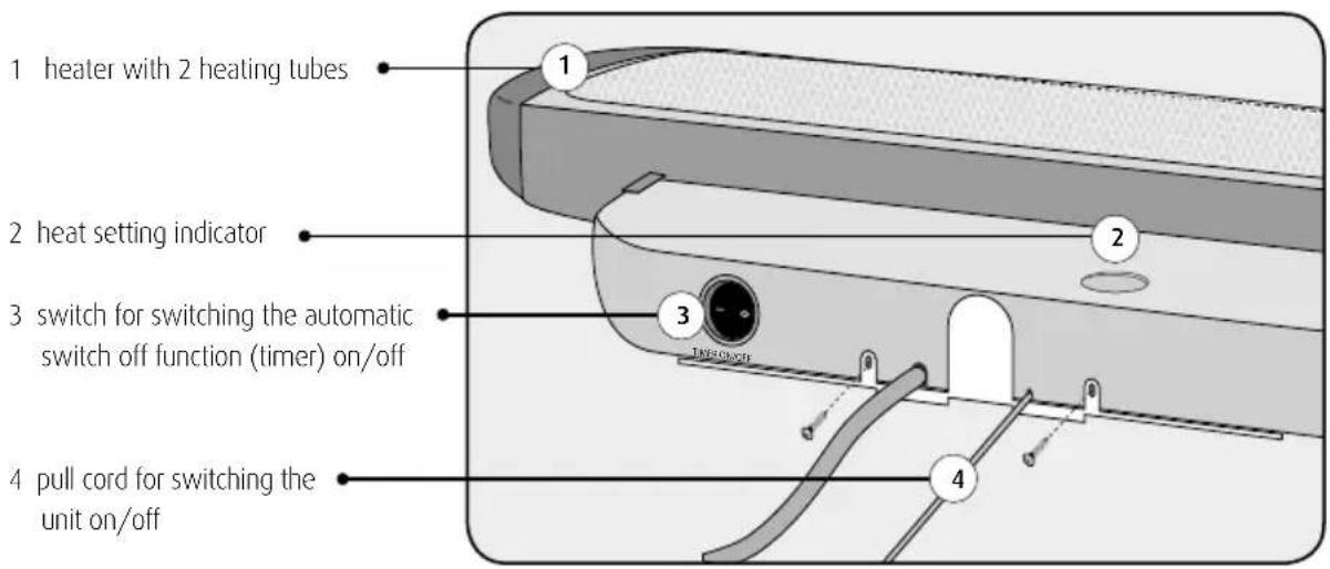
text_image
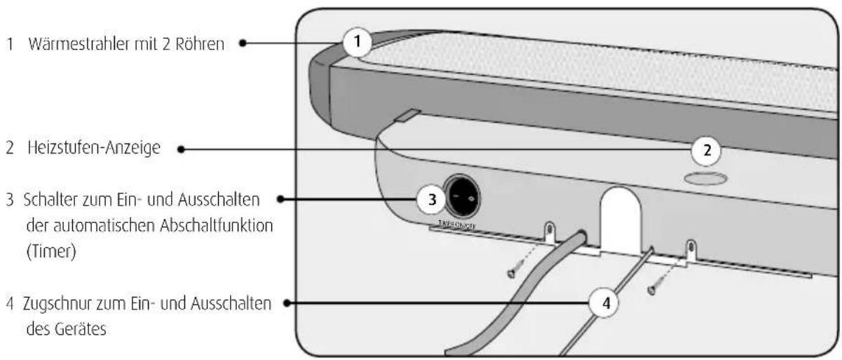
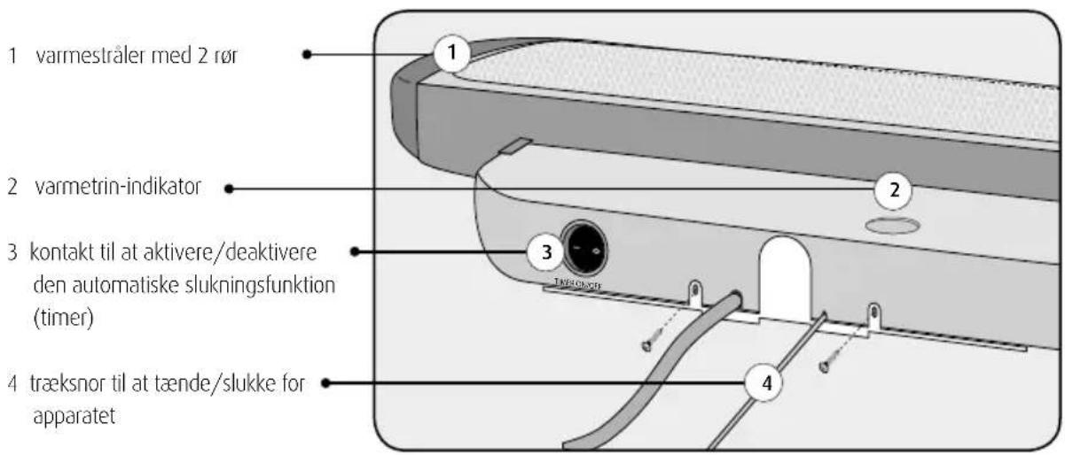
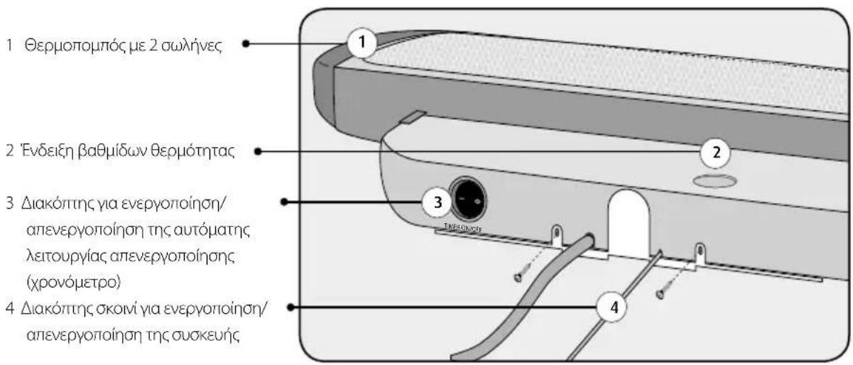
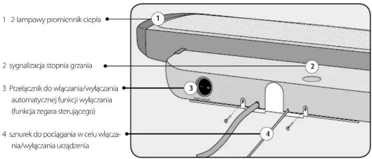
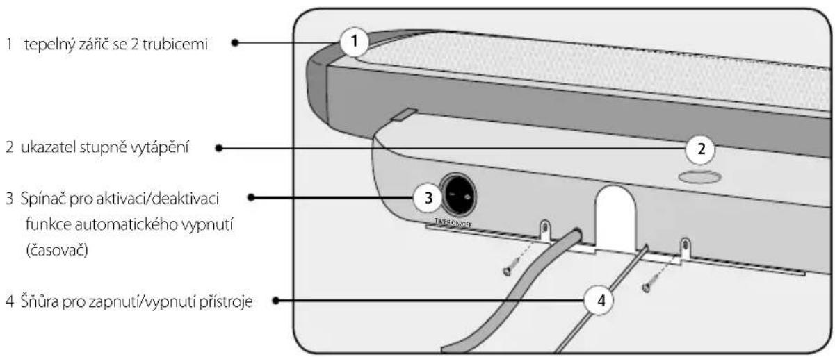
1 heater with 2 heating tubes 2 heat setting indicator 3 switch for switching the automatic switch off function (timer) on/off 4 pull cord for switching the unit on/offAssembly
Please fold out the inside cover of your user manual for a graphic illustration of the assembly process.
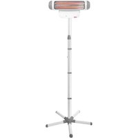
Assembly of changing table heater with pedestal
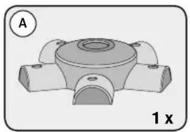
- Insert the 5 feet (B) into the foot connector system (A) as shown in fig. A1.
- Place the foot cover (C) on top (fig. A2).
- Insert the lower attachment tube (D) into the opening (fig. A3).
- Fix the lower attachment tube in position by inserting the plastic screw (E) from below (fig. A4).
- Slide a cable holder (G) over the lower attachment tube (fig. A5).
- Connect the middle attachment tube (H) with the groove to the lower attachment tube as shown in fig. A6 and turn the middle attachment tube until the holes in both tubes align.
- Fix the middle attachment tube into place using the supplied screw (H) and a Philips screwdriver.
- Slide the remaining cable holder (G) over the middle tube and connect the upper attachment tube (I) to the middle attachment tube (fig. A7). Fix the upper attachment tube in position using the supplied screw and a Philips screwdriver.
- Remove the assembly plate from the unit as shown in fig. A8.
- Place the changing table heater (J) on the pedestal and fix it in position with the plastic screw (F) (fig. A9).
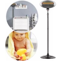
- Open the grey locking screw of the upper attachment tube (fig. A10) and set the changing table heater to the desired height using the telescopic rod. Ensure that a minimum distance of 100 cm to the changing table is observed. Adjust the unit to the desired height by closing the locking screw.
- Secure the cable by pushing it into the cable holders (fig. A11).
- Position the changing table heater in the desired location, out of reach of children and observing the specified minimum distances. Ensure that the pedestal is positioned securely on a level surface.
Note: For an installation with fewer than 5 feet (for example due to limited space), the user must ensure stability of the changing table heater pedestal by other means. Never place a changing table heater with fewer than 5 feet freely in a room.
Wall-mounted assembly of changing table heater
- Remove the assembly plate from the unit as shown in fig. B1.
- Hold the wall bracket on the wall taking into account the minimum distances (fig. B2) and mark the drill holes with a pencil. Use a spirit level to ensure the bracket is level.
- Bolt the wall bracket to the wall (fig. B3) using the supplied screws and wall plugs (J).
- Slide the changing table heater into the relevant grooves on the wall bracket (fig. B3).
- Screw the changing table heater to the wall bracket (fig. B4) using the screws removed in fig. B1.
Safety instructions for wall installation:
- The changing table heater must be mounted on the wall in a stationary and level position. It must not be mounted on the ceiling!
- The changing table heater must not be mounted on wood, plastic or other flammable materials or under plug sockets.
- IMPORTANT! Minimum distances: The minimum distance between the heater and the changing table is 100 cm. A minimum distance of 35 cm between the heater and the ceiling must be observed at all times. The heater must be placed at least 65 cm away from furniture and flammable materials. Fire hazard in case of non-compliance!
- For installation in bathrooms or shower rooms, the regulations of the local utility company must be observed. The heater must be positioned in such a manner that the pull switch cannot be reached from the bath or shower.
- Never install the unit above a bath tub!
Putting into operation
- Insert the mains plug into the power socket (fig. 1).
- Pull the pull cord (fig. 2) to switch the heater on. The heater has two heat settings: 400 W (level „1“) and 800 W (level „2“).
3 Pull the cord again to change the heat setting or switch the unit off (level „0“).
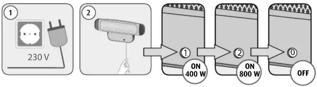
flowchart
graph LR
    A["1: 230 V power plug"] --> B["2: Sensor connected to a cable"]
    B --> C["ON 400 W"]
    C --> D["2: ON 800 W"]
    D --> E["OFF"]
Automatic switch-off function
- To activate the automatic switch-off function, switch the timer switch on the bottom of the unit to the „ON“ position. The unit switches off automatically after 10 minutes.
- There are 2 ways of switching the unit on after automatic switch-off:
- Move the rocker switch to the „Off“ position or
- pull the pull cord, until the heat setting indicator shows „0“. If the pull cord is pulled again on heat setting „1“ or „2“, the unit is switched on again.
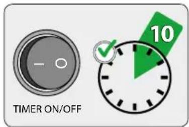
text_image
TIMER ON/OFF 10Switch-off if tilted
The unit has an automatic switch-off function if tilted. If the angle exceeds 25^ (for example if the unit is mounted on the ceiling), the power supply to the unit is cut. The unit switches back on automatically, when it is upright again.
Troubleshooting
| issue possible causes remedial action | ||
| No heat radiation despite heat setting indicator showing „1“ or „2“. | · The power plug is not connected properly.· The automatic switch-off function (timer) is activated.· The automatic tilt switch-off function is activated, because the angle of the heater exceeds 25°. | · Check the power plug.· Turn the „Timer” to „Off” or switch the unit off and then on again by repeatedly pulling the pull cord.· Ensure that the heater is level and fixed to the wall or the pedestal is upright. |
Cleaning, maintenance
- Before cleaning, ensure that the unit is switched off and cooled down (pull out the power plug). Clean the surface with a dry, slightly damp cloth. The reflector and heating tubes must be cleaned by skilled personnel only.
• This product does not require any special maintenance.
• Repairs must be carried out by skilled personnel only.
Warranty
Please retain your receipt, the user manual and part number.
Claims under warranty or under warranty commitments are to be processed by the dealer alone.
The technical specification, information and characteristics of the product described herein have been compiled to the best of our knowledge and belief and are correct at the time of printing. Any information provided by reer should be correct and authoritative. Nevertheless, reer does not accept liability for potential errors in this document and reserves the right to make changes to the product design and/or specifications without prior notice. Reproduction and disclosure of information contained in this copyright-protected document, in any form or by any means - graphical, electronic or mechanical by photocopying, recording on tape or storage in a data retrieval system - even in part, require prior written consent from reer.

natural_image
Symbol of a trash bin crossed with a diagonal line, no text or numbers presentEnvironmental protection:
At the end of its life, this product must not be disposed of as normal domestic waste, but should be recycled at a collection point for electrical appliances. Please see the relevant symbol on the product, in the user manual and packaging. Materials can be recycled as specified. An important contribution to the protection of the environment can be made by reusing the unit, recycling its components or otherwise reusing old appliances. Please contact your local council to find out more about an appropriate disposal centre.

reer GmbH
Muehlstr.41 • 71229 Leonberg • Germany
www.reer.de
natural_image
3D mechanical component diagram with labeled section A and multiplier 1 x (no text or symbols on the object itself)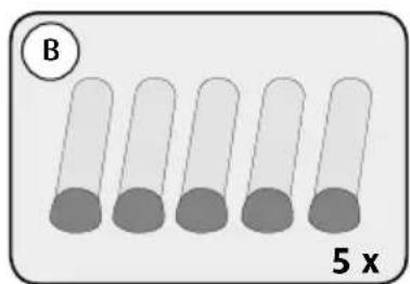
text_image
B 5 x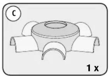
natural_image
Technical diagram of a mechanical component with three curved arms and a central circular feature, labeled '1 x' (no text or symbols beyond labels)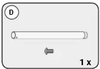
text_image
D 1 x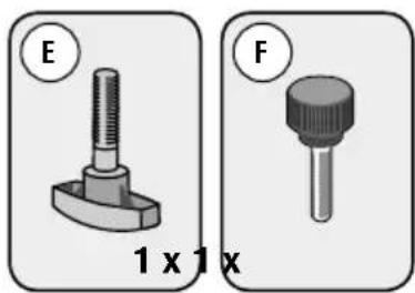
natural_image
Two mechanical component diagrams labeled E and F, showing different sizes (1x1x) with no visible text or symbols beyond labels.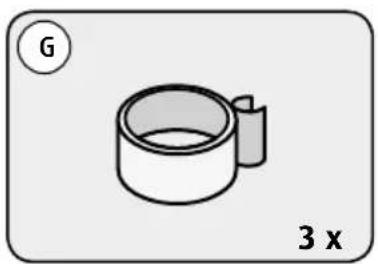
natural_image
Simple line drawing of a cylindrical object with a handle, labeled 'G' and '3 x' (no text or symbols on the object itself)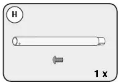
text_image
H 1 x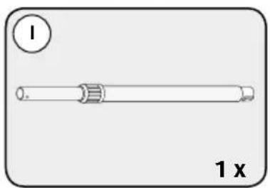
natural_image
Simple line drawing of a cylindrical object with a side hole and a circular label (no text or symbols on the object itself)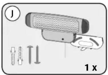
text_image
J 1 xflowchart
graph LR
    A["1: 230 V power plug"] --> B["2: Sensor connected to a cable"]
    B --> C["ON 400 W"]
    C --> D["2: ON 800 W"]
    D --> E["OFF"]
Apagado automático
natural_image
Symbol of a trash bin with crossed lines indicating no waste or restriction, accompanied by a black rectangular block at the bottom (no text or symbols present)natural_image
3D mechanical component diagram with labeled section A and multiplier 1 x (no text or symbols on the object itself)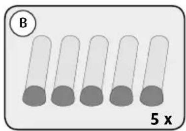
text_image
B 5 x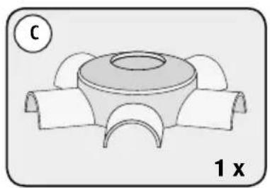
natural_image
Technical diagram of a mechanical component with three curved arms and a central circular feature, labeled '1 x' (no text or symbols beyond labels)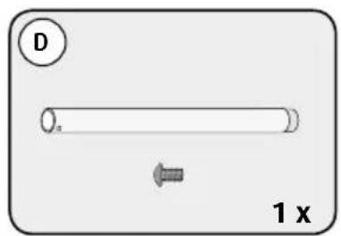
text_image
D 1 x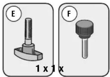
natural_image
Two mechanical component diagrams labeled E and F, showing different types of fasteners or tools (no text or symbols on the objects themselves)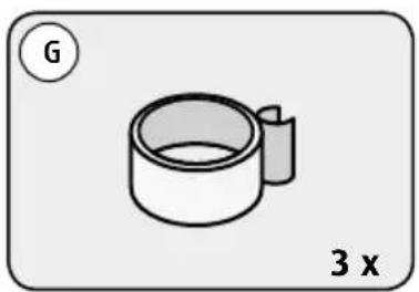
natural_image
Simple line drawing of a cylindrical object with a handle, labeled 'G' and '3 x' (no text or symbols on the object itself)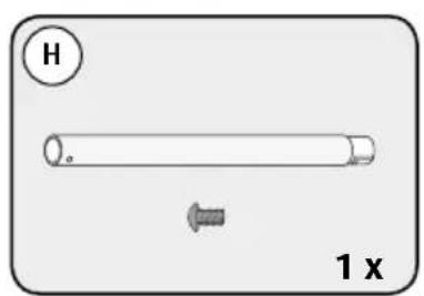
text_image
H 1 x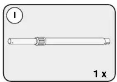
natural_image
Simple line drawing of a cylindrical object with a side label '1 x' and a circled number 1 (no text or symbols on the object itself)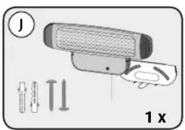
text_image
J 1 xflowchart
graph LR
    A["1: 230 V power plug"] --> B["2: Sensor with cable"]
    B --> C["ON 400 W power rating"]
    C --> D["2: ON 800 W power rating"]
    D --> E["OFF: Off signal"]
natural_image
Symbol of a trash bin crossed with a diagonal line, no text or numbers presentnatural_image
3D mechanical component diagram with labeled section A and multiplier 1 x (no text or symbols on the object itself)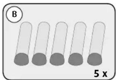
text_image
B 5 x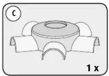
natural_image
Technical diagram of a mechanical component with three curved arms and a central circular feature, labeled '1 x' (no text or symbols beyond labels)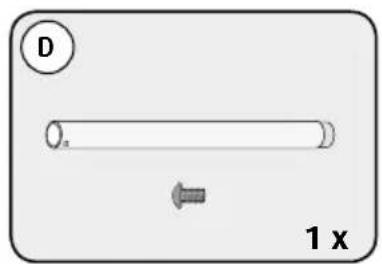
text_image
D 1 x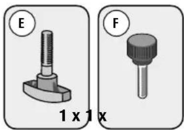
natural_image
Two mechanical component diagrams labeled E and F, showing different sizes (1x1x) with no visible text or symbols beyond labels.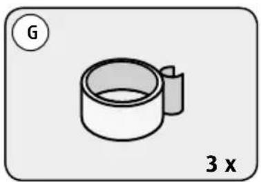
natural_image
Simple line drawing of a cylindrical object with a handle, labeled 'G' and '3 x' (no text or symbols on the object itself)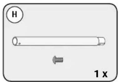
text_image
H 1 x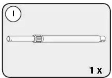
natural_image
Simple line drawing of a cylindrical object with a side hole, labeled '1 x' (no text or symbols on the object itself)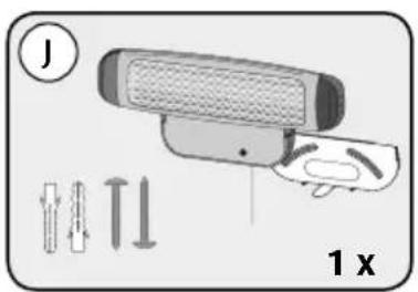
text_image
J 1 xflowchart
graph LR
    A["1: 230 V power plug"] --> B["2: Sensor with cable"]
    B --> C["ON 400 W power rating"]
    C --> D["2: ON 800 W power rating"]
    D --> E["OFF: Off signal"]
natural_image
Symbol of a trash bin crossed with a diagonal line, no text or numbers presentnatural_image
3D mechanical component diagram with labeled section A and multiplier 1 x (no text or symbols on the object itself)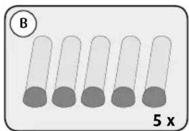
text_image
B 5 x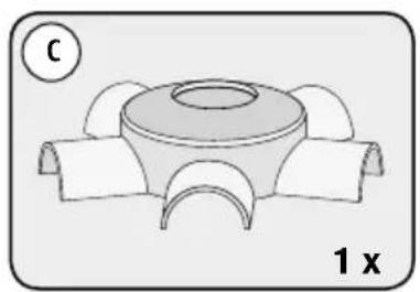
natural_image
Technical diagram of a mechanical component with three curved arms and a central circular feature, labeled '1 x' (no text or symbols beyond labels)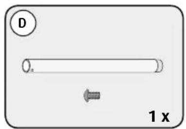
text_image
D 1 x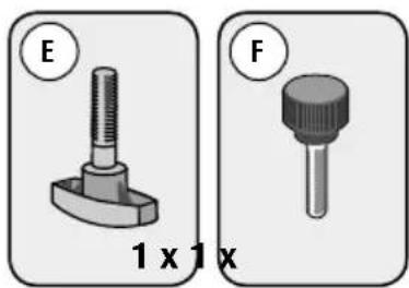
natural_image
Two mechanical component diagrams labeled E and F, showing different sizes (1x1x) with no visible text or symbols.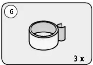
natural_image
Simple line drawing of a cylindrical object with a handle, labeled 'G' and '3 x' (no text or symbols on the object itself)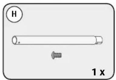
text_image
H 1 x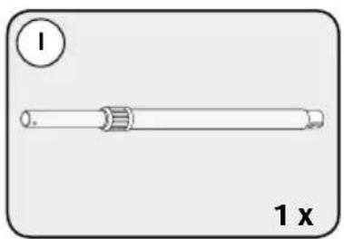
natural_image
Simple line drawing of a cylindrical object with a side hole, labeled '1 x' (no text or symbols on the object itself)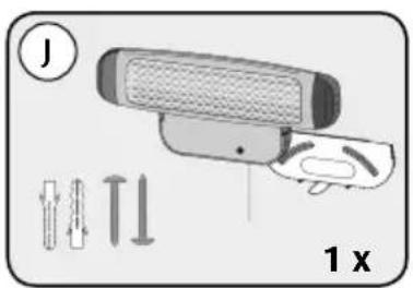
text_image
J 1 xflowchart
graph LR
    A["1: 230 V power plug"] --> B["2: Sensor connected to a cable"]
    B --> C["ON 400 W power switch"]
    C --> D["2: ON 800 W power switch"]
    D --> E["OFF"]
natural_image
Symbol of a trash bin with crossed lines indicating no waste or restriction, and a solid black rectangle below (no text or labels)natural_image
3D mechanical component diagram with labeled section A and multiplier 1 x (no text or symbols on the object itself)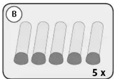
text_image
B 5 x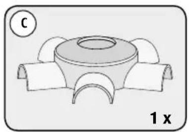
natural_image
Technical diagram of a mechanical component with three curved arms and a central circular feature, labeled '1 x' (no text or symbols beyond labels)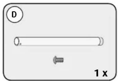
text_image
D 1 x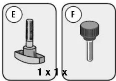
natural_image
Two mechanical component diagrams labeled E and F, showing different sizes (1x1x) with no visible text or symbols beyond labels.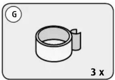
natural_image
Simple line drawing of a cylindrical object with a handle, labeled 'G' and '3 x' (no text or symbols on the object itself)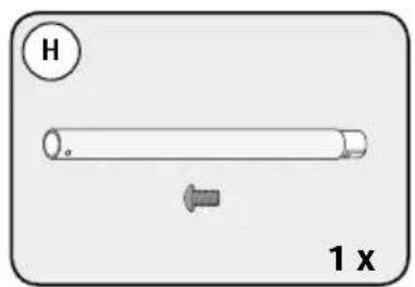
text_image
H 1 x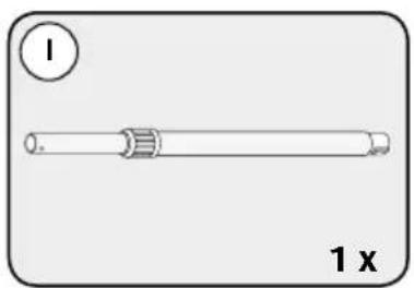
natural_image
Simple line drawing of a cylindrical object with a side label '1' and the number '1 x' below (no text or symbols on the object itself)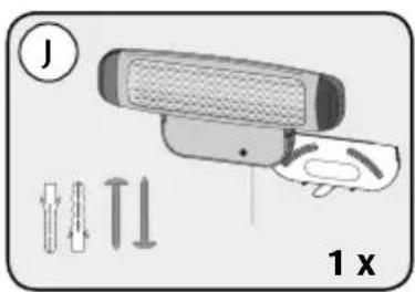
text_image
J 1 xKomponentbetegnelse
flowchart
graph LR
    A["1: 230 V power plug"] --> B["2: Sensor with cable"]
    B --> C["ON 400 W power rating"]
    C --> D["2: ON 800 W power rating"]
    D --> E["OFF: Off signal"]
Automatisk stop
natural_image
Symbol of a trash bin with crossed lines indicating no waste or restriction (no text or numbers present)natural_image
3D mechanical component diagram with labeled section A and multiplier 1 x (no text or symbols on the object itself)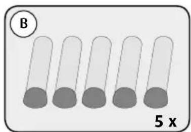
text_image
B 5 x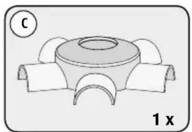
natural_image
Diagram of a mechanical component with a central circular feature and four curved arms, labeled '1 x' (no text or symbols on the diagram itself)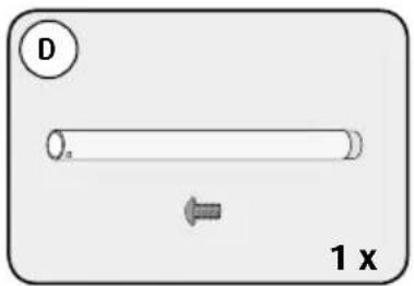
text_image
D 1 x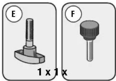
natural_image
Two mechanical component diagrams labeled E and F, showing different types of features (no text or symbols beyond labels)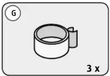
natural_image
Simple line drawing of a cup with a handle, labeled 'G' and '3 x' (no text or symbols on the cup itself)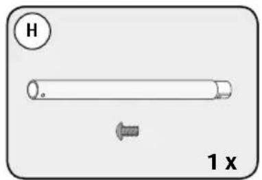
text_image
H 1 x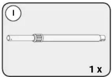
natural_image
Simple line drawing of a cylindrical object with a side label '1 x' and a circled number 1 (no text or symbols on the object itself)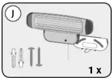
text_image
J 1 xΧαρακτηρισμός μερών
flowchart
graph LR
    A["1: 230 V power plug"] --> B["2: Sensor connected to a cable"]
    B --> C["ON 400 W power rating"]
    C --> D["2: ON 800 W power rating"]
    D --> E["OFF: Off signal"]
natural_image
Symbol of a trash bin crossed with a diagonal line, no text or numbers presentnatural_image
3D mechanical component diagram with labeled section A and multiplier 1 x (no text or symbols on the object itself)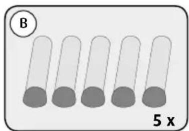
text_image
B 5 x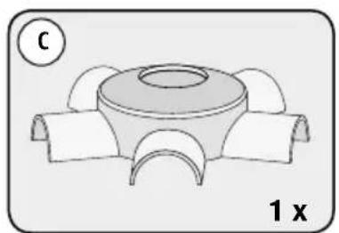
natural_image
Diagram of a mechanical component with a central circular feature and four curved arms, labeled '1 x' (no text or symbols on the diagram itself)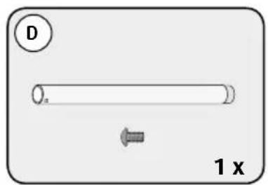
text_image
D 1 x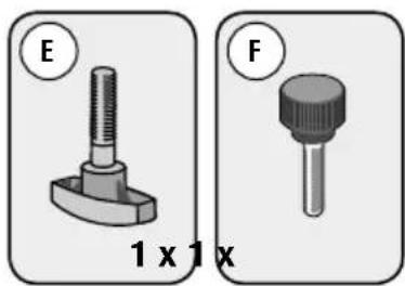
natural_image
Two mechanical component diagrams labeled E and F, showing different sizes (1x1x) with no visible text or symbols beyond labels.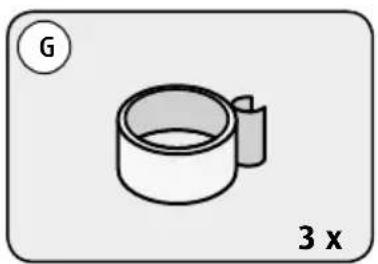
natural_image
Simple line drawing of a cylindrical object with a handle, labeled 'G' and '3 x' (no text or symbols on the object itself)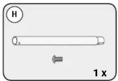
text_image
H 1 x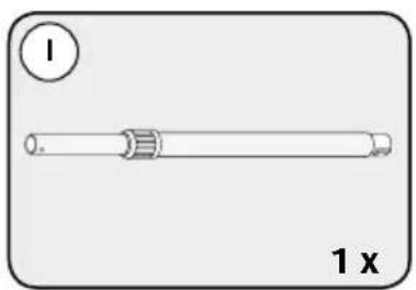
natural_image
Simple line drawing of a cylindrical object with a side label '1' and the number '1 x' below (no text or symbols on the object itself)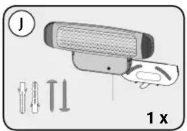
text_image
J 1 xNazwa podzespołu
flowchart
graph LR
    A["1: 230 V power plug"] --> B["2: Sensor connected to a cable"]
    B --> C["ON 400 W power switch"]
    C --> D["2: ON 800 W power switch"]
    D --> E["OFF"]
natural_image
Symbol of a trash bin crossed with a diagonal line, no text or numbers presentnatural_image
3D mechanical component diagram with labeled section A and multiplier 1 x (no text or symbols on the object itself)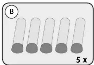
text_image
B 5 x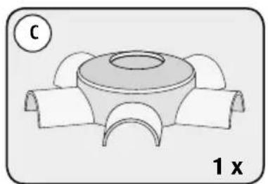
natural_image
Diagram of a mechanical component with a central circular feature and four curved arms, labeled '1 x' (no text or symbols on the diagram itself)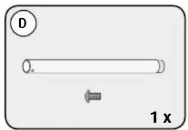
text_image
D 1 x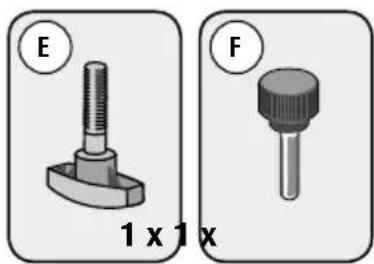
natural_image
Two mechanical component diagrams labeled E and F, showing different sizes (1x1x) with no visible text or symbols beyond labels.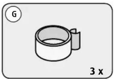
natural_image
Simple line drawing of a cylindrical object with a handle, labeled 'G' and '3 x' (no text or symbols on the object itself)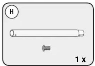
text_image
H 1 x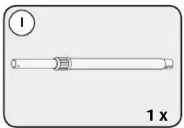
natural_image
Simple line drawing of a cylindrical object with a side label '1' and the number '1 x' below (no text or symbols on the object itself)
text_image
J 1 xPopis částí
flowchart
graph LR
    A["1: 230 V power plug"] --> B["2: Sensor connected to a cable"]
    B --> C["ON 400 W power rating"]
    C --> D["2: ON 800 W power rating"]
    D --> E["OFF: Off signal"]