BELLE BHB 27 - Hammer Lescha - Free user manual and instructions
Find the device manual for free BELLE BHB 27 Lescha in PDF.

User questions about BELLE BHB 27 Lescha
0 question about this device. Answer the ones you know or ask your own.
Ask a new question about this device
Download the instructions for your Hammer in PDF format for free! Find your manual BELLE BHB 27 - Lescha and take your electronic device back in hand. On this page are published all the documents necessary for the use of your device. BELLE BHB 27 by Lescha.
USER MANUAL BELLE BHB 27 Lescha
natural_image
Abstract white bird-like shape on gradient background (no text or symbols)ALTRAD
GB Operators Manual 6
US Operators Manual 20
F Manuel De L'Opérateur 34
E Manual del Operador 48
P Manual de Operação 62
D Bedienungshandbuch 76
PL Instrukcja Obsługi 90
RUS Руководство для оператора 104
BG Оператор Ръчен 118
CZ Na'vod K Obzluze 132
RO Manual de Utilizare 146
HUN Kezelők Kézi 160
HR Uputstvo za rukovatelja 174
SK Príručka pre obsluhu 188

text_image
Belle GROUPBHB BREAKERS
natural_image
Technical line drawing of a mechanical device with articulated arms and mounting brackets (no text or symbols)202
- Spare Parts Book
- Pièces détachées
- Libro Despiece
- Lista de Peças
- Ersatzteilhandbuch
- Lista Części Zamiennych
- Запасные части Книга
- Част Списък
- Část Barevný pruh
- Lista Pieselor de Schimb
- Részek Oldalra döl
- Rezervni djelovi Knjiga
- Zoznam náhradných dielov
EC DECLARATION OF CONFORMITY / DECLARATION CE DE CONFORMITE / DECLARACIÓN
We, Belle Group Sheen UK, Sheen, Nr. Buxton, Derbyshire, SK17 0EU, GB, hereby certify that if the product described within this certificate is bought from an authorised Belle Group dealer within the EEC, it conforms to the following EEC directives: 2006/42/CE (This directive replaces directive 98/37/EC), Electromagnetic Compatibility Directive 2004/108/CE (as amended by 89/336/EEC, 92/31/EEC & 93/68 EEC). The Waste Electrical and Electronic Equipment (WEEE) 2002/96/CE, the low voltage directive 2006/95/CE, BS EN ISO 12100-1:2003 Safety of machinery and associated harmonised standards, where applicable. Noise emissions conform to directives 2000/14/EC Annex VI & 2005/88/EC, for machines under article 12 the notified body is AV Technology Limited, AVTECH house, Birdhall Lane, Cheadle Heath, Stockport, Cheshire, SK3 0XU, GB.
Noise Technical Files are held at the Belle Group Head Office address which is stated above.

PRODUCT TYPE ...... TYPE DE PRODUIT...... TIPO DE PRODUCTO......
MODEL...... MODELE...... MODELO ....
Managing Director - On behalf of BELLE GROUP (SHEEN) UK.
Place of Declaration - Sheen, Nr. Buxton, Derbyshire, SK17 0EU, UK
Lieu de déclaration - Sheen, Nr. Buxton, Derbyshire, SK17 0EU, UK
Sted i erklæring - Sheen, Nr. Buxton, Derbyshire, SK17 0EU, UK
Date of Declaration - 2007
natural_image
Empty white rectangle with dashed border (no text or symbols)Подпись:
Alla kirjutanud:
Paraksts:
Pasiraše:
Подпис:
Υπογραφή:

text_image
O.NathRay Neilson
Director General - in numele BELLE GROUP (SHEEN), UK
This manual has been written to help you operate and service the Belle Group BHB Hydraulic Breaker safely. This manual is intended for dealers and operators of the Belle Group BHB Hydraulic Breaker.
Foreword
The ‘Machine Description’ section helps you to familiarise yourself with the machine's layout, controls and Decals.
The ‘Safety Instructions’ sections explain how to use the machine to ensure your safety and the safety of the general public.
The ‘Operating Instructions’ section helps you with the setting up and use of the machine.
The 'Service & Maintenance' section is to help you with the general maintenance and servicing of your machine.
The ‘Environment’ section gives instructions on how to handle the recycling of discarded apparatus in an environmentally friendly way.
The 'Trouble Shooting Guide' helps you if you have a problem with your machine.
The 'Warranty' section details the nature of the warranty cover and claims procedure.
The ‘Declaration Of Conformity’ section shows the standards that the machine has been built to.
Directives with regard to the notations.
Text in this manual to which special attention must be paid are shown in the following way:

CAUTION
The product can be at risk. The machine or yourself can be damaged or injured if procedures are not carried out in the correct way.

WARNING
The life of the operator can be at risk.

WARNING

WARNING
Before you operate or carry out any maintenance on this machine YOU MUST READ and STUDY this manual.
KNOW how to safely use the unit's controls and what you must do for safe maintenance.
(Be sure that you know how to switch the machine off before you switch on, in case you get into diffi culty.)
ALWAYS wear or use the proper safety items required for your personal protection.
If you have ANY QUESTIONS about the safe use or maintenance of this unit, ASK YOUR SUPERVISOR OR CONTACT THE BELLE GROUP +44 (0)1298 84606

Contents
How to use this manual....6
Warning 6
Machine Description....7
Technical Data....8
Matching The Breaker To The Power Source 9
Safety Instructions....10 - 12
General Safety 13
Recommended Hydraulic Oil....13
Storage 13
Environment 14
Pre-Start Checks 14
Start and Stop Procedure....14
Operating Instructions 15 - 17
EHTMA - Code Of Practice 17
Service & Maintenance 18
Trouble Shooting Guide 19
Warranty 19
Declaration of Conformity....2
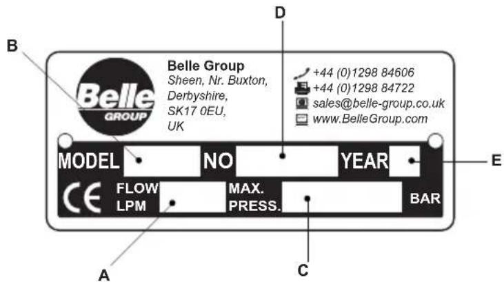
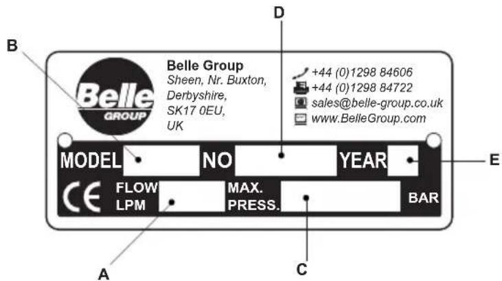
Serial Plate
A. Maximum permitted Hydraulic Oil Flow.
B. Breaker Model.
C. Maximum permitted Hydraulic Pressure.
D. Serial Number.
E. Year of Manufacture.
text_image
Belle Group Sheen, Nr. Buxton, Derbyshire, SK17 0EU, UK D Belle GROUP MODEL NO YEAR +44 (0)1298 84606 +44 (0)1298 84722 sales@belle-group.co.uk www.BelleGroup.com E CE FLOW MAX. BAR LPM PRESS. A C BARDecals
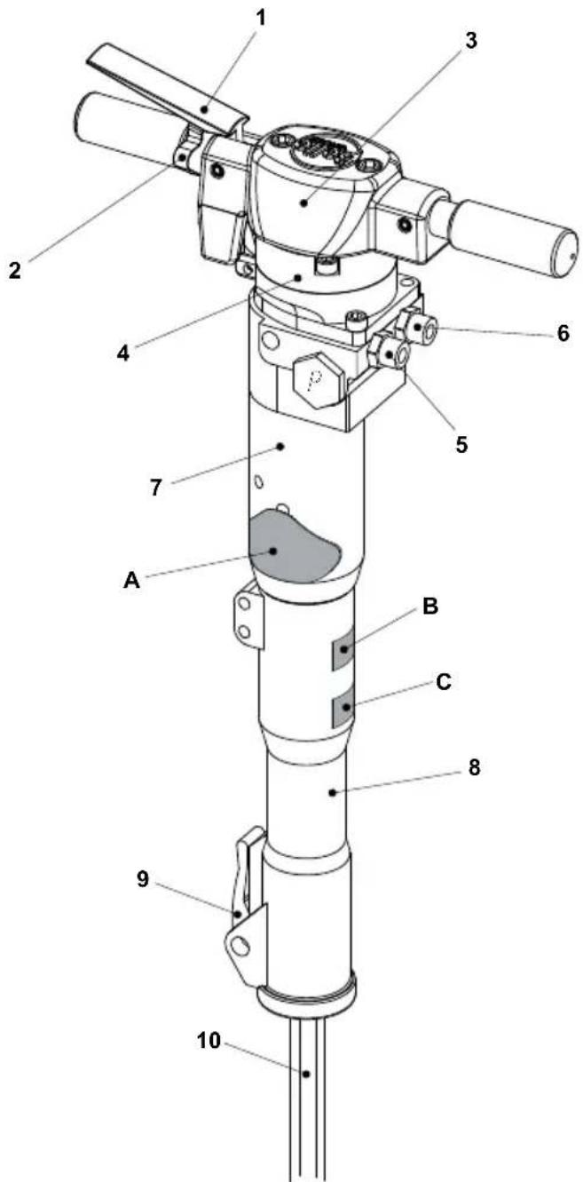
A. Model Decal
This Decal shows the Model Name of the Breaker. E.g 'BHB 19'
B. Noise Decal
This Decal shows the Noise Level of the machine.
C. CE Decal
This Decal indicates whether the machine conforms to CE Regulations. The Decal will not be found on USA machines.
Machine Components
- Trigger
- Trigger Lock
- Head
- Accumulator
- Oil In (P*)
- Oil Return (T**) (Restrictor - Please see 'Technical Data' section)
- Main Body
- Nose Section
- 'Steel' Latch
- Steel
* P = Pressure
** T = Tank
text_image
Technical diagram of a mechanical device with numbered components for identification| Model | BHB12 | BHB19 | BHB19 USA | BHB23 | BHB23 UC | BHB25X |
| Restrictor | Open | Open | Open | Open | Open | Open |
| Weight (Kg) | 14 | 19 | 19 | 23.5 | 23.5 | 27.5 |
| Hydraulic Flowrate (Ltrs/Min) | 20 | 20 | 20 | 20 | 20 | 20 |
| Working Pressure (Bar) | 70 - 90 | 90 - 110 | 90 - 110 | 90 - 110 | 90 - 110 | 90 - 110 |
| Max Pressure (Bar) | 160 | 160 | 160 | 160 | 160 | 160 |
| Max. Return Line Pressure (Bar) | 10 | 10 | 10 | 10 | 10 | 10 |
| EHTMA Category | C | C | C | C | C | C |
| Hydraulic Connections | 12 BSP | 12 BSP | 12 JIC | 12 BSP | 12 JIC | 12 BSP |
| Flat Faced, Quick Release, Non-Drip Couplings | ||||||
| Hydraulic Oil Type | ||||||
| - Below 30°C | ISO VG T32 | |||||
| - Above 30°C | ISO VG T46 | |||||
| Blow Frequency (Blows/Min) | 2400 | 1600 | 1600 | 1600 | 1600 | 1600 |
| Accumulator Gas Pressure (Bar) | 40 | 40 | 40 | 40 | 40 | 40 |
| Steel Size (mm) | 22 x 82 | 25 x 108 | 32 x 152 | 25 x 108 | 28 x 160 | 32 x 160 |
| Recommended Power Pack | Cub 20/90Midi 20/140 | Cub 20/90Midi 20/140 | Midi 20/140Major 20/140 | Cub 20/90Midi 20/140 | Midi 20/140Major 20/140 | Midi 20/140Major 20/140 |
| Preliminary Vibration - Cub ( m/s^2 ) | 14.13 | 9.78 | 9.78 | 9.78 | 9.78 | 6.00 |
| Preliminary Vibration - Midi ( m/s^2 ) | 16.08 | 11.97 | 11.97 | 11.97 | 11.97 | 6.00 |
| Noise Level (dB(A)) | 105 | 107 | 107 | 107 | 108 | 108 |
| Model BHB25 BHB27 * BHB30 USA * | |||||
| Restrictor (mm) 3.8 3.4 Open 3.8 | Open | ||||
| Weight (Kg) | 28 | 28 | 28 | 31.5 | 31.5 |
| Hydraulic Flowrate (Ltrs/Min) 20 20 30 | 20 | 30 | |||
| Working Pressure (Bar) 105 - 125 105 - 125 105 - 125 | 105 - 125 | ||||
| Max Pressure (Bar) | 160 | 160 | 160 | ||
| Max. Return Line Pressure (Bar) | 20 20 20 20 20 | ||||
| EHTMA Category | C | C | D | C | D |
| Hydraulic Connections | ^1/_2 BSP | ^1/_2 BSP | ^1/_2 BSP | ^1/_2 JIC | ^1/_2 JIC |
| Flat Faced, Quick Release, Non-Drip Couplings | |||||
| Hydraulic Oil Type | |||||
| - Below 30°C | ISO VG T32 | ||||
| - Above 30°C | ISO VG T46 | ||||
| Blow Frequency (Blows/Min) | 1300 | 1300 | 2150 | 1150 | 1850 |
| Accumulator Gas | Pressure | (Bar) | 50 | 50 | |
| Steel Size (mm) | 32 x 160 | 32 x 160 | 32 x 160 | 32 x 152 | 32 x 152 |
| Recommended Power Pack | Midi 20/140 Major 20/140 | Midi 20/140 Major 20/140 | Major 30/140 | Midi 20/140 Major 20/140 | Major 30/140 |
| Preliminary Vibration (m/s2) | 11.1 | 11.8 | 18.61 | 10.75 | 16.06 |
| Noise Level (dB(A)) | 108 | 108 | 108 | ||
* NOTE:- Breakers are supplied with alternative return pipe restrictors. Please ensure correct restrictor is fitted for 20 or 30 Litre supply. (Restrictor size is marked on the restrictor body) NO MARKINGS = OPEN RESTRICTOR More information can be found on the next page.
Matching The Breaker To The Power Pack
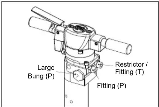
Restrictor / Fitting Identifi cation
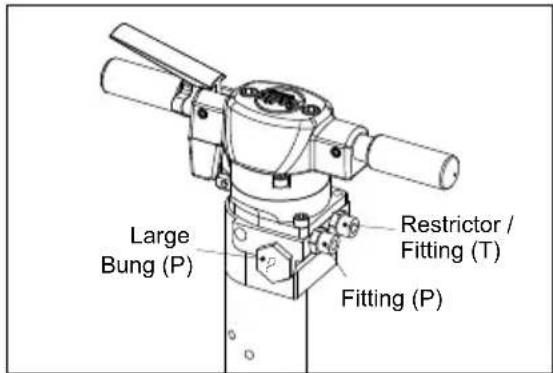
The tank Restrictors / Fittings can be identified by using this simple procedure.
Check your Breaker and identify the P and T side of the body by looking for a letter stamp on the large bung. This can be found on the side of the Breaker as shown in the diagram. This stamp also corresponds to the Restrictor / Fitting on the same side of the Breaker
For example: In the image the bung on the left hand side of the Breaker is clearly stamped with the letter P, so the fi tting on the left hand side will be the Pressure Line and the right hand side will be the Tank / Return Line.
P = Pressure side of the Breaker
T = Tank / Return side of the Breaker
text_image
Large Bung (P) Restrictor / Fitting (T) Fitting (P)
WARNING
You must only ever change the TANK Line Restrictor / Fitting as you may cause harm to your Breaker and Power Pack if the PRESSURE Line Fitting is changed.
BHB27 & BHB30 USA ONLY!!
At delivery, the Breaker is intended for an oil flow of 30 Ltrs/Min (E.H.T.M.A. Category D). If the Breaker is to be connected to a Hydraulic Power Pack with an Oil Flow of 20 Ltrs/Min (E.H.T.M.A. Category C) the Restrictor / Fitting of the tank line (T) must be replaced:- See Item 6 of 'Machine Description' section.
Restrictors / Fittings
| Oil Flow Rate EHTMA Category Part Number Restrictor Size Notes | |
| 20 Ltrs/Min C 971/99061 3.4mm Delivered with the Breaker (Loose) | |
| 30 Ltrs/Min D 971/99006 No Restrictor (Open) Fitted onto the Breaker |

CAUTION
Connecting the Breaker to a higher oil flow rate may cause damaged to the Power Pack or to the Breaker. DO NOT attempt to change the Restrictor immediately after use as the Hydraulic Oil will be hot.
Replacing The Restrictor
- Disconnect the Breaker from the Power Pack.
- Fix the Breaker in vertical position to a vice or in another way so that the Breaker is fixed.
Do not place it on the Nose Section because the Breaker can tilt. - Remove the Tank Line Hose, leaving the Restrictor / Fitting in the Breaker body. Remember to have an oil pan ready to take the oil spill from the Breaker. Drain the oil from the T-Hose into the oil pan.
- Loosen the Restrictor on the Breaker. Remember to have an oil pan ready to take the oil spill from the Breaker.
- Remove the Seal from the old Fitting / Restrictor. Fit the new Restrictor using the existing Seal, ensuring that the internal Allen Key head in the Restrictor is fitted into the Breaker body first. Tighten to a Torque Setting of 90±2 Nm.
- Refi t the Hose and tighten to a Torque Setting of 50±2 Nm.
- Reconnect the Breaker to Power Pack and check it for leakage.
NOTE:- When the Breaker is modified to another oil flow rate, do not connect a Power Pack with higher oil flow rate. We recommend that the EHTMA Label on the Breaker is changed to Category C (Green) (Supplied loose with Breaker), if Restrictor (971/99061) is fitted. Section A of the Serial Plate (See 'Machine Description' section) should also be amended.

WARNING
To reduce risk of serious injury or death to yourself or others, read these safety instructions before operating the machine. Post these safety instructions at work locations, provide copies to employees, and make sure that everyone reads the safety instructions before operating or servicing the machine. Follow all safety instructions given in this manual. All the safety instructions conform to the applicable laws and directives of the European Union. You should also respect any additional national/regional directives. In countries outside the European Union, the valid local statutes and regulations shall apply. Any additional regional laws and regulations must be observed.
Machine and Tool operating Hazards
Sudden or unexpected movement of the machine may occur during operating, which may cause injuries. Furthermore, losing your balance or slipping may cause injury. To reduce risks:
• Make sure that you always keep a stable position with your feet as far apart as the width of your shoulders, and keeping your body weight balanced out.
- Stand firmly and always hold on to the machine with both hands.
- Do not start the machine when it is lying on the ground.
• Make sure that the handles are clean and free from grease and oil.
Unintentional start of the machine may cause injury!
- Keep your hands away from the start and stop device until you are ready to start work.
The working tool is exposed to heavy strains when the machine is used and after a certain amount of use the tool may break due to fatigue. If the tool breaks, there may be sudden or strong movements. Such sudden or strong movements may cause serious injury.
• Make sure that you always keep a stable position with your feet as far apart as the width of your shoulders, and keeping your body weight balanced.
- Keep your hands and feet away from the working tool.
- Do not 'ride' on the machine with one leg over the handle, since you could be seriously injured if the tool were to break suddenly.
- Check regularly for wear to the working tool, and check whether there are any signs of damage or visible cracks.
An incorrect dimension of the working tool's shank can result in the working tool being lost or slipping out during operation. A working tool that is lost or slips out can cause personal injury.
- Before inserting the work tool, make sure that the shank's dimensions are correct for use in the machine.
• Working tools without a collar may not be used.
If the tool retainer on the machine is not in a locked position, the tool can be ejected with force, which can cause personal injury.
- Once the working tool has been mounted and locked, the locking function must be checked by pulling the working tool outwards forcefully.
• Make sure that the tool is fully inserted and the tool retainer is in the locked position before the machine is started. - Never point the working tool at yourself or anyone else.
Starting the machine while changing the working tool may cause personal injury.
- Before changing the tool, stop the machine, switch off the hydraulic oil supply and bleed the machine by activating the start and stop device.
A hydraulic hose that comes loose can lash around and cause personal injury or death. To reduce risks:
- Check that the hydraulic hose and the connections are not damaged.
- Check that all hydraulic connections are properly attached.
- Never attempt to disconnect a hydraulic hose that is pressurized. First switch off the hydraulic oil flow by the power pack and then bleed the machine by activating the start and stop device.
Accumulator Hazard
The machine has a pressure accumulator. The pressure accumulator may only be charged with nitrogen gas ( N_2 ).
- Only authorized personnel are qualified to work with the accumulator.
- Do not perform any work on the machine, the connections or any hoses, when the hydraulic system is pressurized.
NOTE!:- If the maximum working pressure for the machine is exceeded, the accumulator can be overcharged, which can result in material damage.
- Always run the machine with the correct working pressure. See "Technical Data" section.
Hydraulic Oil and Lubrication Hazards
Thin jets of hydraulic oil under high pressure can penetrate the skin and cause permanent damage.
- Never use your hands when searching for oil leaks.
- Keep your face away from any possible leaks.
- Immediately seek medical attention if hydraulic oil has penetrated the skin.
Spilled hydraulic oil can cause accidents by causing slippery conditions and will also harm the environment.
- Handle the hydraulic oil with care.
• Take care of all spilled oil and handle it according to your local safety and environmental regulations.
Hot hydraulic oil can cause burns.
- Never dismount the machine when the hydraulic oil is hot.
Hydraulic oil can cause eczema when it comes in contact with the skin.
- Avoid getting hydraulic oil on your hands.
• Always use protective gloves when working with hydraulic oil.
Grease can cause eczema when it comes in contact with the skin.
- Avoid getting grease on your hands.
Explosion and Fire Hazard
Breaking, drilling and working with certain materials can cause sparks, which may ignite explosive gases and cause explosions. Explosions may cause serious injury or death. To reduce such risk of explosion:
- Never operate the machine in any explosive environment.
- Do not use the machine near fl ammable materials, fumes or dust.
• Make sure that there are no undetected sources of gas.
Electrical/Concealed Object Hazards
The machine is not electrically insulated. If the machine comes into contact with electricity, serious injuries or death may result.
• To reduce the risk of such injury or death, never operate the machine near any electric wire or other source of electricity.
- Make sure that there are no concealed wires or other sources of electricity.
During breaking, concealed wires and pipes constitute a danger that can result in serious injury.
- Before you start breaking, check the composition of the material you are to work on.
- Watch out for concealed cables and pipes e.g. electricity, telephone, water, gas and sewage lines etc.
• If the tool seems to have hit a concealed object, switch off the machine immediately.
• Make sure that there is no danger before continuing.
Projectile Hazard
During breaking, drilling or hammering, splinters or other particles from the worked material may become projectiles and cause personal injury by striking the operator or other persons.
- Use approved personal protective equipment, including impact resistant safety glasses with side protection, to reduce the risk of being injured by a projectile.
Noise Hazard
High sound levels may cause permanent hearing loss.
- Use hearing protection in accordance with occupational health and safety regulations.
Silica/Dust Hazard
Exposure to crystalline silica (sometimes called 'silica dust') as a result of breaking, drilling, hammering, or other activities involving rock, concrete, asphalt or other materials may cause silicosis (a serious lung disease), silicosis-related illnesses, cancer, or death. Silica is a major component of rock, sand and mineral ores. To reduce silica exposure:
• Use proper engineering controls to reduce the amount of silica in the air and the build-up of dust on equipment and surfaces.
Examples of such controls include: Exhaust ventilation and dust collection systems, water sprays, and wet drilling. Make sure that controls are properly installed and maintained.
- Wear, maintain, and correctly use approved particulate respirators when engineering controls alone are not adequate to reduce exposure below permissible levels.
• Participate in air monitoring, medical exams, and training programs offered by your employer and when required by law.
- Wear washable or disposable protective clothes at the worksite; shower and change into clean clothes before leaving the worksite to reduce exposure of silica to yourself, other persons, cars, homes, and other areas.
- Do not eat, drink, or use tobacco products in areas where there is dust containing crystalline silica.
- Wash your hands and face before eating, drinking, or using tobacco products outside of the exposure area.
• Work with your employer to reduce silica exposure at your worksite.
Some dust, fumes or other airborne material created during use of the machine may contain chemicals known to the State of California to cause cancer and birth defects or other reproductive harm. Some examples of such chemicals are:
• Crystalline silica and cement and other masonry products.
- Arsenic and chromium from chemically-treated rubber.
- Lead from lead based paints.
To reduce your exposure to these chemicals, work in a well ventilated area, and work with approved safety equipment, such as dust masks that are specially designed to filter out microscopic particles.
Machine Modifi cation Hazard
Any machine modification not approved by Belle Group may result in serious injuries to yourself or others.
• The machine must not be modified without Belle Groups permission.
- Use only original parts and accessories approved by Belle Group.
Vibration Hazard
Normal and proper use of the machine exposes the operator to vibration. Regular and frequent exposure to vibration may cause, contribute to, or aggravate injury or disorders to the operator's fingers, hands, wrists, arms, shoulders and/or other body parts, including debilitating and/or permanent injuries or disorders that may develop gradually over periods of weeks, months, or years. Such injury or disorder may include damage to the blood circulatory system, damage to the nervous system, damage to joints, and possibly damage to other body structures.
If numbness, tingling, pain, clumsiness, weakened grip, whitening of the skin, or other symptoms occur at any time, when operating the machine or when not operating the machine, do not resume operating the machine and seek medical attention. Continued use of the machine after the occurrence of any such symptom may increase the risk of symptoms becoming more severe and/or permanent.
The following may help to reduce exposure to vibration for the operator:
- Let the tool do the job. Use a minimum hand grip consistent with proper control and safe operation.
- When the impact mechanism is activated, the only body contact with the machine you should have is your hands on the handles. Avoid any other contact, e.g. supporting any part of the body against the machine or leaning onto the machine trying to increase the feed force. It is also important not to keep the trigger engaged while extracting the tool from the broken work surface.
- Make sure that the inserted tool is wellmaintained (including sharpness, if a cutting tool), not worn out, and of the proper size. Working tools that are not well-maintained, or that are worn out, or that are not of the proper size result in longer time to complete a task (and a longer period of exposure to vibration) and may result in or contribute to higher levels of vibration exposure.
- Immediately stop working if the machine suddenly starts to vibrate strongly. Before resuming the work, find and remove the cause of the increased vibrations.
- Comply with the recommended hydraulic pressure when operating the machine. Either higher or lower hydraulic pressure has the potential of resulting in higher levels of vibration.
- Do not grab, hold or touch the inserted tool when using the machine.
- Participate in health surveillance or monitoring, medical exams, and training programs offered by your employer and when required by law.
NOTE!:- See the Noise and Vibration Levels for the machine, which can be found in the Technical Data section
General Safety
- Machines and accessories must only be used for their intended purpose.
- Only qualified and trained persons may operate or maintain the machine.
- Learn how the machine is switched off in the event of an emergency.
- Release the start and stop device immediately in all cases of power supply interruption.
- Always inspect the equipment prior to use. Do not use the equipment if you suspect that it is damaged.
• Always use your common sense and good judgment.
• Pay attention and look at what you are doing. - Do not use the machine when you are tired or under the influence of drugs, alcohol or anything else that may affect your vision, reactions or judgment.
- Participate in safety and training courses.
- Never strike or abuse any equipment.
- Keep the machine and tools in a safe place, out of the reach of children and locked up.
• Make sure that all the attached and related equipment is properly maintained.
• Decals bearing important information regarding personal safety and care of the machine are supplied with every machine.
• Make sure that the decals are always legible. - New decals can be ordered from the Spare Parts list.
• Make sure that no unauthorized personnel trespass into the working zone. - Keep the workplace clean and free from foreign objects.
- Never point a hydraulic hose at yourself or anyone else.
PPE (Personal Protective Equipment)
Always use approved protective equipment. Operators and all other persons in the working area must wear protective equipment, including at a minimum:
- Protective helmet.
- Safety Goggles,
- Gloves,
- Ear Defenders,
- Dust Mask
• Steel Toe capped footwear.
Wear clothing suitable for the work you are doing. Tie back long hair and remove any jewellery which may catch in the equipment's moving parts.
Recommended Hydraulic Oil

In order to protect the environment, Belle Group recommends the use of biologically degradable hydraulic oil.
- Viscosity (preferred) 20-40 cSt.
• Viscosity (permitted) 15-100 cSt.
• Viscosity index Min. 100.
Standard mineral or synthetic oil can be used. When the breaker is used continuously, the oil temperature will stabilise at a level which is called the working temperature. This will, depending on the type of work and the cooling capacity of the hydraulic system, be between 20-40°C (68-104°F) above the ambient temperature.
At working temperature, the oil viscosity must lie within the preferred limits. The viscosity index indicates the connection between viscosity and temperature. This is the reason why a high viscosity is preferred, because then the oil can be used within a wider temperature range. The breaker shall not be used, if oil viscosity fails to remain within the permitted area, or if the working temperature of the oil does not fall between ÷20^ ( ÷4^ ) and 70^ ( 158^ ).
Storage

- Disconnect the breaker's hoses from the power source. See "Start and Stop Procedure" section
- Make sure that the breaker is properly cleaned before storage.
- In case of long-term storage, the striking piston must be protected against corrosion. This is done by pressing it (through the chisel bushing) to its upper position by means of a tool placed up-side-down. As the quick-release couplings are blocked when disassembled, the striking piston must be pressed upwards with the hoses mounted but the power pack unactivated.
• Always store the machine in a dry place.

A used machine must be treated and disposed of in such a way that the greatest possible portion of the material can be recycled and any negative influence on the environment is kept as low as possible.
NOTE:-
Before a used machine is scrapped, it must be emptied and cleaned from all hydraulic oil. Remaining hydraulic oil must be deposited.


Pre-Start Checks
Pre-Start Checks
The following checks should be made each time you start to use the breaker. All these checks concern the serviceability of the breaker. Some concern your safety:
- Clean all Decals. Replace any that are missing or cannot be read. These can be ordered from the Spare Parts list.
- Inspect the hoses generally for signs of damage.
- Inspect the working tool for wear and damage.
- Do not use an excessively worn or damaged tool.
- Connect the tool.
- Ensure that the hydraulic couplings are clean and fully serviceable.
- Do not invert the breaker without first isolating it from the power source. The working tool might be fired out while connecting it, if the breaker is connected to the power source.
- Ensure that any power source you plan to use is compatible with the breaker model used (see the "Technical data" section). Belle Group recommends using an LFD oil flow divider, if the flow from the power source can exceed the maximum allowed oil flow.

Start and Stop Procedure
Starting
1) Check that the 'Steel' is in good condition and pressed fully home in the nose of the breaker.
2) Check that the latch is locked, so that the 'Steel' does not fall out.
3) Remove the protective caps from the quick-release couplings.
4) Clean the quick-release couplings if needed and connect the tail-hoses to the extension hoses of the power unit.
5) Place the breaker at a right angle on the material to be broken and activate the trigger lever.
Stopping
1) Release the trigger. Press the breaker against the surface, until the breaker has stopped completely.
2) Stop the power source.
3) Disconnect the hoses and fit the protective caps to the quick-release couplings.
Operating Instructions
To reduce the risk of serious injury or death to yourself or others, before operating the machine, read the Safety instructions section found on the previous pages of this booklet.
Design and Function
The Belle Group BHB Range of handheld Hydraulic Breakers are sturdy and reliable breakers designed for working together with Belle Group Hydraulic Power Packs.
The handheld Breakers are available in many different sizes with varying impact energies and commonly used tool sizes. The handheld Breakers are designed for various jobs from light brickwork and asphalt jobs to heavy duty jobs in reinforced concrete.
All Belle Group BHB Range handheld breakers are delivered with 12 " tail-hoses with 12 " Flat-Face quick-release couplings for easy connection to the Belle Group Hydraulic Power Packs.
Choosing the correct hydraulic breaker for a task
It is important to choose the correct size of hydraulic breaker for the work to be performed.
A hydraulic breaker that is too small means that the work will take longer.
A breaker that is too big means that there must be frequent repositioning, which is unnecessarily tiring for the operator.
A simple rule for choosing the correct size of hydraulic breaker is that a normal sized piece of broken material should be removed from the workpiece within 10–20 seconds of operation.
- If it takes less than 10 seconds a smaller hydraulic breaker should be selected.
• If it takes more than 20 seconds a larger hydraulic breaker should be selected.
Installation
Hoses
For connection of the breaker, the hydraulic hose must be approved for a working pressure of at least 200 bar (2900 psi) and have a 12 " inner diameter. To resist exterior wear and tear, we recommend using a 2-layer hydraulic hose. The breaker connection marked P (pump) is oil inlet, and the connection marked T (tank) is oil outlet.
Quick-release couplings
The original Belle Group hydraulic hoses are fitted with Flat-Face quick-release couplings that are strong and easy to clean. The quick-release couplings are fitted so that the male connection supplies oil and the female connection receives oil.
Fitting and Removing the Breaker 'Steel'
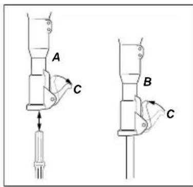
Whenever fi tting/removing the 'Steel', the following instructions must be observed:
1) To prevent an accidental start, switch off the oil supply. Bleed the machine by pressing the start/stop device. Disconnect the machine from the power source.
2) Remove the 'Steel' by swinging the latch (C) fully down (Image A).
3) Fit a 'Steel' by ensuring that the latch (C) is fully down. Then insert the 'Steel' in the breaker as shown and swing the latch (C) fully up (Image B).
text_image
A C B C
text_image
Technical diagram showing a mechanical component with labeled part '2' and a downward arrow indicating force or direction.Checking for wear
Using a working tool with a worn out shank leads to increased machine vibrations. To avoid increased vibrations, check the shank for wear before the working tool is fitted in the machine.
Use the checking gauge that corresponds to the working tool's shank dimension. If the gauge's hole (2) can be pushed down on the working tool's shank, this means that the shank is worn out and the working tool should be replaced.
* Note:- The Checking Gauge is not supplied with the machine.
Choosing working tool
A correct working tool is a prerequisite for good operation. To avoid unnecessary machine damage, it is important to choose working tools of a high quality.

natural_image
Pure geometric line drawing of a symmetrical shape with no text or symbolsThe narrow chisel should be used for demolition and cutting work in concrete and other types of hard material.

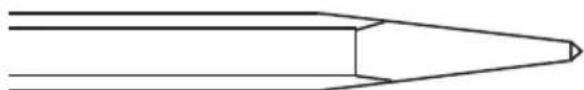
natural_image
Simple line drawing of a pointed object with no text or symbolsThe moil point should only be used for creating holes in concrete and other types of hard material.
natural_image
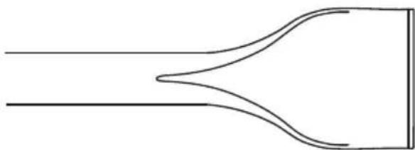
Pure diagram of fluid flow through a funnel-like channel with no text or symbolsThe wide chisel should be used in soft materials e.g. asphalt and frozen ground.

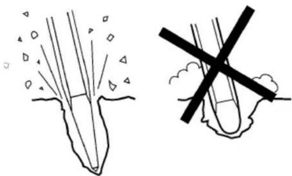
natural_image
Two hand-drawn diagrams showing a pointed object with rays and a cross-shaped object embedded in ground (no text or symbols)Always use a sharp tool to be able to work effectively. A worn out tool causes increased vibrations and the operation will take longer.
Operating Instructions
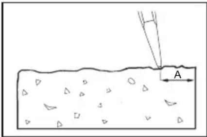
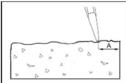
STARTING A CUT
1) Stand steady and make sure that your feet and hands are at a safe distance from the working Breaker.
2) Press the machine against the surface of the workpiece before starting.
3) Adjust the breaking distance (A) so that the working Breaker does not get stuck.
4) Do not try to cut too big a bite.
5) Trying to loosen a working Breaker that is stuck will expose the operator to unnecessary vibrations.
text_image
AOPERATION
1) Let the machine do the work; do not press too hard. The vibration-absorbing handle must absolutely not be pressed all the way down to the base.
2) Hydraulic breakers with vibration-absorbing handles: The feed force should be adapted so that the handles are pressed down "half way". The best vibration damping and breaking effect is achieved at this position.
3) Avoid working in extremely hard materials e.g. granite and reinforcing iron (reinforcement bar), which would cause substantial vibrations.
4) Any form of idling, operating without working tool or operating without adapted feed force must be avoided.
5) When no feed force is applied, the start and stop device must not be activated.
6) Check regularly that the machine is well lubricated.
WHEN TAKING A BREAK
1) During all breaks you must put the machine away so that there is no risk that it will be unintentionally started.
2) In the event of a longer break or when leaving the workplace: Switch off the hydraulic oil supply and then bleed the machine by activating the start and stop device.
EHTMA - Code Of Practice

EUROPEAN HYDRAULIC TOOL MANUFACTURERS ASSOCIATION CODE OF PRACTICE – HYDRAULIC BREAKERS
Before Starting. Refer to manufacturer's operating instructions.
Compatibility. Hydraulic Breakers are designed to operate at a specific Flow and Pressure. Equipment produced by EHTMA members carries a triangular colour coded range identification label. Check that both the Tool and Power Unit have the same identification label before operation. It is imperative that Power Units and Tools having different colour codings are not interconnected as this practice is both inefficient and dangerous.
For reference the EHTMA colour code is as follows:-
| Classification | Colour Code. | Flow l/min | Max pressure Bar. |
| A | Yellow | 5.5 – 6.5 | 180 |
| B | Blue | 13.5 – 16.5 | 172 |
| C | Green | 18.0 – 22.0 | 138 |
| D | Brown | 27.0 – 33.0 | 138 |
| E | Red | 36.0 – 44.0 | 138 |
| F | Black | 45.0 – 55.0 | 138 |
| G | Orange | 54.0 – 66.0 | 138 |
| Z | Grey | 9.0 – 11.0 | 180 |
If in doubt consult the equipment manufacturer.
Characteristics. Operators not familiar with the use of hydraulic tools should note the following points:-
1) Hydraulic breakers are usually more powerful than the equivalent weight pneumatic tools.
2) The body of the hydraulic breaker and the supply hoses will become quite warm during normal operation.
3) As the breaker has no exhaust it is generally much quieter in operation. This should not be taken as a lack of power.
Steel Selection It is essential that the correct type and size of steel is chosen if optimum performance is to be achieved, with particular reference being made to the shank length and across fl at dimensions.
Recommendations as follows:-
Material. Recommended Steel
Concrete. Pointed or narrow bladed chisels.
Tarmac. Sharp edged wide bladed tools with straight cutting edges.
Asphalt. Sharp edged tools with thin section and curved cutting edges.
General Trenchwork. Spades and Digger steels.
ALWAYS USE SHARP STEELS - Blunt steels increase vibration and reduce efficiency.
Regular maintenance is a prerequisite for keeping the machine safe and effective. Carefully follow the operating instructions.
Before undertaking any maintenance or changing the working tool on hydraulic machines, always switch off the oil supply and bleed the machine by depressing the start and stop device. Then disconnect the hydraulic hose from the machine.
- Use only authorized parts. Any damage or malfunction caused by unauthorized parts will not be covered by Warranty or Product Liability.
- Change damaged parts immediately.
- Replace worn components in good time.
• Always clean the hose couplings before mounting or dismounting.
• Always plug hoses and nipples with clean and tight plugs when dismounting. - When cleaning mechanical parts with solvent, make sure to comply with occupational health and safety regulations, and make sure that there is satisfactory ventilation.
- Inspection and service on the accumulator must only be done by a certifi ed person.
- For major service to the machine, contact the Belle Group or your nearest authorised dealer.
NOTE!:- Maintenance must only be done by suitably qualified and competent persons. Before doing any maintenance, make sure that the machine is safe and correctly sited on the ground.
| Routine Maintenance Every Week Every 3 Every 600Months Hrs / Yearly | |||
| Clean and inspect the machine. √ | |||
| Grease the Handle Guides with Silicone (E-Type Handles only) | √ | ||
| Check Hoses and Fittings for cracks or leaks. Replace if necessary. | √ | ||
| Inspect the ‘Steel’ for wear and damage. Do not use an worn or damaged ‘Steel’. | √ | ||
| Check for general damage to the machine. √ | |||
| If the machine is equipped with Vibration-Absorbing handles, their function should be checked. | √ | ||
| Check that the handles are moving freely (up - down) and do not jam. | √ | ||
| Check that the springs are not damaged. | √ | ||
| Check tightness of nuts, bolts, screws and hose fittings. | √ | ||
| Check the Chisel bushing in the nose for wear and damage. | √ | ||
| Check moving parts, seals and bolts for wear and cracks. Replace if necessary. | √ | ||
| Check the function of the machine. | √ |
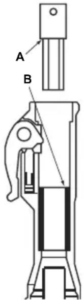
For the machine to maintain the specified vibration values, this should always be checked:
Too big a clearance between the working tool's shank and the chisel bushing will generate increased vibrations. To avoid exposure to excessive vibrations, check the chisel bushing for wear every day. Use the gauge that corresponds to the working tool's shank dimension. If the gauge's part (A) can be pushed fully into the chisel bushing (B), the bushing is worn out and must be replaced! See also "Checking for wear" section for checking the working tool's shank.
text_image
A BTroubleshooting Guide

| Problem Cause Remedy | ||
| Breaker does not work. No Pressure is not built up when trigger is activated. | or incorrect flow/pressure. Check flow/p | pressure by means of test equipment. |
| P and T hoses interchanged. male quick-release coupling (i.e. the tail-hose of the breaker P connection is fitted with female coupling). | Check connection. Standard connection has oil flowing from | |
| Insufficient activation of trigger valve. | Adjust trigger lever (if adjustable) or replace defective parts. | |
| Seals defect in spool channel of valve housing. | Dismount, check and replace seals. | |
| Breaker does not work. Pressure is built up when trigger is activated defective. | Back pressure too high. | Make direct tank connection. Max. back pressure 10-15 bar (150-200 psi) measured at breaker. |
| Quick-release coupling in return line | Locate and replace defective coupling. | |
| Striking piston sticks, possibly due to thickening of cylinder. | Push the breaker hard against the Breaker ‘Steel’. | |
| Chamfer/polish the edge slightly at the cylinder dashpot (where the cylinder bore changes size). | ||
| Check oil viscosity. Thin oil increases the risk of thickening. | ||
| Spool / reversing spool or auxiliary spool sticking easily. | Dismount and check that all parts move. Polish slightly if necessary. | |
| Seals defective. | Dismount, check and replace. | |
| Breaker runs weakly or irregularly | Insufficient flow. | Check flow/pressure. |
| Seals defective. | Replace seals. | |
| Wear, internal leakage. | Dismantle, check and replace defective or worn parts. | |
| Check impurity of oil and oil viscosity at working temperature. | ||
| Thin oil = increased internal leakage. | ||
| Insuffi cient accumulator charge. | Recharge accumulator. | |
| Diaphragm defective. | Replace diaphragm. | |
| Hoses pulsate | Accumulator defective. | Replace accumulator diaphragm and charge with nitrogen. |
| Oil leaking from breaker. | Seals defective. | Replace seals. |
| ‘Steel’ falls out. | Worn latch. | Replace latch and roll pins. |
| Worn chisel bushing or ‘Steel’. | Replace bushing or ‘Steel’. |
Warranty

Your new Belle Group BHB Hydraulic Breaker is warranted to the original purchaser for a period of one-year (12 months) from the original date of purchase. The Belle Group warranty is against defects in design, materials and workmanship.
The following are not covered under the Belle Group warranty:
- Damage caused by abuse, misuse, dropping or other similar damage caused by or as a result of failure to follow assembly, operation or user maintenance instructions.
- Alterations, additions or repairs carried out by persons other than Belle Group or their recognised agents.
- Transportation or shipment costs to and from Belle Group or their recognised agents, for repair or assessment against a warranty claim, on any machine.
- Materials and/or labour costs to renew, repair or replace components due to fair wear and tear.
Belle Group and/or their recognised agents, directors, employees or insurers will not be held liable for consequential or other damages, losses or expenses in connection with or by reason of or the inability to use the machine for any purpose.
Warranty Claims
All warranty claims should firstly be directed to Belle Group, either by telephone, by Fax, by Email, or in writing.
For warranty claims:
Belle Group Warranty Department,
Sheen, Nr. Buxton
Derbyshire
SK17 0EU
England.
Tel : +44 (0)1298 84606, Fax : +44 (0)1298 84722 Email : warranty@belle-group.co.uk
This manual has been written to help you operate and service the Belle Group BHB Hydraulic Breaker safely. This manual is intended for dealers and operators of the Belle Group BHB Hydraulic Breaker.
Foreword
The ‘Machine Description’ section helps you to familiarise yourself with the machine's layout, controls and Decals.
The ‘Safety Instructions’ sections explain how to use the machine to ensure your safety and the safety of the general public.
The ‘Operating Instructions’ section helps you with the setting up and use of the machine.
The 'Service & Maintenance' section is to help you with the general maintenance and servicing of your machine.
The ‘Environment’ section gives instructions on how to handle the recycling of discarded apparatus in an environmentally friendly way.
The ‘Trouble Shooting Guide’ helps you if you have a problem with your machine.
The 'Warranty' section details the nature of the warranty cover and claims procedure.
The ‘Declaration Of Conformity’ section shows the standards that the machine has been built to.
Directives with regard to the notations.
Text in this manual to which special attention must be paid are shown in the following way:

CAUTION
The product can be at risk. The machine or yourself can be damaged or injured if procedures are not carried out in the correct way.

WARNING
The life of the operator can be at risk.

WARNING

WARNING
Before you operate or carry out any maintenance on this machine YOU MUST READ and STUDY this manual.
KNOW how to safely use the unit's controls and what you must do for safe maintenance.
(Be sure that you know how to switch the machine off before you switch on, in case you get into diffi culty.)
ALWAYS wear or use the proper safety items required for your personal protection.
If you have ANY QUESTIONS about the safe use or maintenance of this unit, ASK YOUR SUPERVISOR OR CONTACT THE BELLE GROUP +44 (0)1298 84606

Contents
How to use this manual....6
Warning 6
Machine Description....7
Technical Data....8
Matching The Breaker To The Power Source ....
Safety Instructions....9 - 11
General Safety 12
Recommended Hydraulic Oil....17
Storage 17
Environment 17
Pre-Start Checks 12
Start and Stop Procedure....12
Operating Instructions 13 - 15
EHTMA - Code Of Practice 15
Service & Maintenance 16
Trouble Shooting Guide .... 18
Warranty 18
Declaration of Conformity....2
Serial Plate
A. Maximum permitted Hydraulic Oil Flow.
B. Breaker Model.
C. Maximum permitted Hydraulic Pressure.
D. Serial Number.
E. Year of Manufacture.
text_image
Belle Group Sheen, Nr. Buxton, Derbyshire, SK17 0EU, UK D Belle GROUP MODEL NO YEAR +44 (0)1298 84606 +44 (0)1298 84722 sales@belle-group.co.uk www.BelleGroup.com E CE FLOW MAX. BAR LPM PRESS. A C BARDecals
A. Model Decal
This Decal shows the Model Name of the Breaker. E.g 'BHB 19'
B. Noise Decal
This Decal shows the Noise Level of the machine.
C. CE Decal
This Decal indicates whether the machine conforms to CE Regulations. The Decal will not be found on USA machines.
Machine Components
- Trigger
- Trigger Lock
- Head
- Accumulator
- Oil In (P*)
- Oil Return (T**) (Restrictor - Please see 'Technical Data' section)
- Main Body
- Nose Section
- 'Steel' Latch
- Steel
* P = Pressure
** T = Tank

text_image
Technical diagram of a mechanical device with numbered components for identification| Model | BHB12 | BHB19 | BHB19 USA | BHB23 | BHB23 UC | BHB25X |
| Restrictor | Open | Open | Open | Open | Open | Open |
| Weight (Ibs) | 31 | 44 | 44 | 44 | 44 | 44 |
| Hydraulic Flowrate (Gals/Min) | 5.3 | 5.3 | 5.3 | 5.3 | 5.3 | 5.3 |
| Working Pressure (PSI) | 1015 - 1305 | 1305 - 1595 | 1305 - 1595 | 1305 - 1595 | 1305 - 1595 | 1305 - 1595 |
| Max Pressure (PSI) | 2302 | 2302 | 2302 | 2302 | 2302 | 2302 |
| Max. Return Line Pressure (PSI) | 145 | 145 | 145 | 145 | 145 | 145 |
| EHTMA Category | C | C | C | C | C | C |
| Hydraulic Connections | ^1/_2 BSP | ^1/_2 BSP | ^1/_2 JIC | ^1/_2 BSP | ^1/_2 JIC | ^1/_2 BSP |
| Flat Faced, Quick Release, Non-Drip Couplings | ||||||
| Hydraulic Oil Type | ||||||
| - Below 30°C | ISO VG T32 | |||||
| - Above 30°C | ISO VG T46 | |||||
| Blow Frequency (Blows/Min) | 2400 | 1600 | 1600 | 1600 | 1600 | 1600 |
| Accumulator Gas Pressure (PSI) | 580 | 580 | 580 | 580 | 580 | 580 |
| Steel Size (in) | 0.86 x 3.2 | 1 x 4.25 | 1.25 x 6 | 1 x 4.25 | 1.1 X 6.25 | 1.25 x 6.25 |
| Recommended Power Pack | Cub 20/90Midi 20/140 | Cub 20/90Midi 20/140 | Midi 20/140Major 20/140 | Cub 20/90Midi 20/140 | Midi 20/140Major 20/140 | Midi 20/140Major 20/140 |
| Preliminary Vibration - Cub ( m/s^2 ) | 14.13 | 9.78 | 9.78 | 9.78 | 9.78 | 6.00 |
| Preliminary Vibration - Midi ( m/s^2 ) | 16.08 | 11.97 | 11.97 | 11.97 | 11.97 | 6.00 |
| Noise Level (dB(A)) | 105 | 107 | 107 | 107 | 107 | 108 |
| Model BHB25 BHB27 * BHB30 USA * | |||||
| Restrictor (mm) 3.8 3.4 Open 3.8 | Open | ||||
| Weight (Kg) | 62 | 62 | 62 | 69 | 69 |
| Hydraulic Flowrate (Ltrs/Min) 5.3 5.3 7.9 | 5.3 | 7.9 | |||
| Working Pressure (PSI) 1522 - 1812 1522 - 1812 1522 - 1812 1522 - 1812 1522 - 1812 | |||||
| Max Pressure (PSI) | 2320 | 2320 | 2320 | 2320 | |
| Max. Return Line Pressure (PSI) 290 290 290 290 290 | |||||
| EHTMA Category | C | C | D | C | D |
| Hydraulic Connections | ^1/_2 BSP | ^1/_2 BSP | ^1/_2 BSP | ^1/_2 JIC | ^1/_2 JIC |
| Flat Faced, Quick Release, Non-Drip Couplings | |||||
| Hydraulic Oil Type | |||||
| - Below 30°C | ISO VG T32 | ||||
| - Above 30°C | ISO VG T46 | ||||
| Blow Frequency (Blows/Min) | 1300 | 1300 | 2150 | 1150 | 1850 |
| Accumulator Gas Pressure (PSI) | 725 | 725 | 725 | 725 | 725 |
| Steel Size (mm) | 1.25 x 6.25 | 1.25 x 6.25 | 1.25 x 6.25 | 1.25 x 6 | 1.25 x 6 |
| Recommended Power Pack | Midi 20/140Major 20/140 | Midi 20/140Major 20/140 | Major 30/140 | Midi 20/140Major 20/140 | Major 30/140 |
| Preliminary Vibration (m/s2) | 11.1 | 11.8 | 18.61 | 10.75 | 16.06 |
| Noise Level (dB(A)) | 108 | 108 | 108 | 108 | 108 |
* NOTE:- Breakers are supplied with alternative return pipe restrictors. Please ensure correct restrictor is fitted for 20 or 30 Litre supply. (Restrictor size is marked on the restrictor body) NO MARKINGS = OPEN RESTRICTOR More information can be found on the next page.
Matching The Breaker To The Power Pack
Restrictor / Fitting Identifi cation
The tank Restrictors / Fittings can be identified by using this simple procedure.
Check your Breaker and identify the P and T side of the body by looking for a letter stamp on the large bung. This can be found on the side of the Breaker as shown in the diagram. This stamp also corresponds to the Restrictor / Fitting on the same side of the Breaker
For example: In the image the bung on the left hand side of the Breaker is clearly stamped with the letter P, so the fi tting on the left hand side will be the Pressure Line and the right hand side will be the Tank / Return Line.
P = Pressure side of the Breaker
T = Tank / Return side of the Breaker
text_image
Large Bung (P) Restrictor / Fitting (T) Fitting (P)
WARNING
You must only ever change the TANK Line Restrictor / Fitting as you may cause harm to your Breaker and Power Pack if the PRESSURE Line Fitting is changed.
BHB27 & BHB30 USA ONLY!!
At delivery, the Breaker is intended for an oil flow of 30 Ltrs/Min (E.H.T.M.A. Category D). If the Breaker is to be connected to a Hydraulic Power Pack with an Oil Flow of 20 Ltrs/Min (E.H.T.M.A. Category C) the Restrictor / Fitting of the tank line (T) must be replaced:- See Item 6 of 'Machine Description' section.
Restrictors / Fittings
| Oil Flow Rate EHTMA Category Part Number Restrictor Size Notes | |
| 20 Ltrs/Min C 971/99061 3.4mm Delivered with the Breaker (Loose) | |
| 30 Ltrs/Min D 971/99006 No Restrictor (Open) Fitted onto the Breaker |

CAUTION
Connecting the Breaker to a higher oil flow rate may cause damaged to the Power Pack or to the Breaker. DO NOT attempt to change the Restrictor immediately after use as the Hydraulic Oil will be hot.
Replacing The Restrictor
- Disconnect the Breaker from the Power Pack.
- Fix the Breaker in vertical position to a vice or in another way so that the Breaker is fixed.
Do not place it on the Nose Section because the Breaker can tilt. - Remove the Tank Line Hose, leaving the Restrictor / Fitting in the Breaker body. Remember to have an oil pan ready to take the oil spill from the Breaker. Drain the oil from the T-Hose into the oil pan.
- Loosen the Restrictor on the Breaker. Remember to have an oil pan ready to take the oil spill from the Breaker.
- Remove the Seal from the old Fitting / Restrictor. Fit the new Restrictor using the existing Seal, ensuring that the internal Allen Key head in the Restrictor is fitted into the Breaker body first. Tighten to a Torque Setting of 90±2 Nm.
- Refi t the Hose and tighten to a Torque Setting of 50±2 Nm.
- Reconnect the Breaker to Power Pack and check it for leakage.
NOTE:- When the Breaker is modified to another oil flow rate, do not connect a Power Pack with higher oil flow rate.
We recommend that the EHTMA Label on the Breaker is changed to Category C (Green) (Supplied loose with Breaker), if Restrictor (971/99061) is fitted. Section A of the Serial Plate (See 'Machine Description' section) should also be amended.

WARNING
To reduce risk of serious injury or death to yourself or others, read these safety instructions before operating the machine. Post these safety instructions at work locations, provide copies to employees, and make sure that everyone reads the safety instructions before operating or servicing the machine. Follow all safety instructions given in this manual. All the safety instructions conform to the applicable laws and directives of the European Union. You should also respect any additional national/regional directives. In countries outside the European Union, the valid local statutes and regulations shall apply. Any additional regional laws and regulations must be observed.
Machine and Tool operating Hazards
Sudden or unexpected movement of the machine may occur during operating, which may cause injuries. Furthermore, losing your balance or slipping may cause injury. To reduce risks:
• Make sure that you always keep a stable position with your feet as far apart as the width of your shoulders, and keeping your body weight balanced out.
- Stand firmly and always hold on to the machine with both hands.
- Do not start the machine when it is lying on the ground.
• Make sure that the handles are clean and free from grease and oil.
Unintentional start of the machine may cause injury!
- Keep your hands away from the start and stop device until you are ready to start work.
The working tool is exposed to heavy strains when the machine is used and after a certain amount of use the tool may break due to fatigue. If the tool breaks, there may be sudden or strong movements. Such sudden or strong movements may cause serious injury.
• Make sure that you always keep a stable position with your feet as far apart as the width of your shoulders, and keeping your body weight balanced.
- Keep your hands and feet away from the working tool.
- Do not 'ride' on the machine with one leg over the handle, since you could be seriously injured if the tool were to break suddenly.
- Check regularly for wear to the working tool, and check whether there are any signs of damage or visible cracks.
An incorrect dimension of the working tool's shank can result in the working tool being lost or slipping out during operation. A working tool that is lost or slips out can cause personal injury.
- Before inserting the work tool, make sure that the shank's dimensions are correct for use in the machine.
• Working tools without a collar may not be used.
If the tool retainer on the machine is not in a locked position, the tool can be ejected with force, which can cause personal injury.
- Once the working tool has been mounted and locked, the locking function must be checked by pulling the working tool outwards forcefully.
• Make sure that the tool is fully inserted and the tool retainer is in the locked position before the machine is started. - Never point the working tool at yourself or anyone else.
Starting the machine while changing the working tool may cause personal injury.
- Before changing the tool, stop the machine, switch off the hydraulic oil supply and bleed the machine by activating the start and stop device.
A hydraulic hose that comes loose can lash around and cause personal injury or death. To reduce risks:
- Check that the hydraulic hose and the connections are not damaged.
- Check that all hydraulic connections are properly attached.
- Never attempt to disconnect a hydraulic hose that is pressurized. First switch off the hydraulic oil flow by the power pack and then bleed the machine by activating the start and stop device.
Accumulator Hazard
The machine has a pressure accumulator. The pressure accumulator may only be charged with nitrogen gas ( N_2 ).
- Only authorized personnel are qualified to work with the accumulator.
- Do not perform any work on the machine, the connections or any hoses, when the hydraulic system is pressurized.
NOTE!:- If the maximum working pressure for the machine is exceeded, the accumulator can be overcharged, which can result in material damage.
- Always run the machine with the correct working pressure. See "Technical Data" section.
Safety Instructions
Hydraulic Oil and Lubrication Hazards
Thin jets of hydraulic oil under high pressure can penetrate the skin and cause permanent damage.
• Never use your hands when searching for oil leaks.
- Keep your face away from any possible leaks.
- Immediately seek medical attention if hydraulic oil has penetrated the skin.
Spilled hydraulic oil can cause accidents by causing slippery conditions and will also harm the environment.
- Handle the hydraulic oil with care.
• Take care of all spilled oil and handle it according to your local safety and environmental regulations.
Hot hydraulic oil can cause burns.
- Never dismount the machine when the hydraulic oil is hot.
Hydraulic oil can cause eczema when it comes in contact with the skin.
- Avoid getting hydraulic oil on your hands.
• Always use protective gloves when working with hydraulic oil.
Grease can cause eczema when it comes in contact with the skin.
- Avoid getting grease on your hands.
Explosion and Fire Hazard
Breaking, drilling and working with certain materials can cause sparks, which may ignite explosive gases and cause explosions. Explosions may cause serious injury or death. To reduce such risk of explosion:
- Never operate the machine in any explosive environment.
- Do not use the machine near fl ammable materials, fumes or dust.
• Make sure that there are no undetected sources of gas.
Electrical/Concealed Object Hazards
The machine is not electrically insulated. If the machine comes into contact with electricity, serious injuries or death may result.
• To reduce the risk of such injury or death, never operate the machine near any electric wire or other source of electricity.
• Make sure that there are no concealed wires or other sources of electricity.
During breaking, concealed wires and pipes constitute a danger that can result in serious injury.
- Before you start breaking, check the composition of the material you are to work on.
- Watch out for concealed cables and pipes e.g. electricity, telephone, water, gas and sewage lines etc.
• If the tool seems to have hit a concealed object, switch off the machine immediately.
• Make sure that there is no danger before continuing.
Projectile Hazard
During breaking, drilling or hammering, splinters or other particles from the worked material may become projectiles and cause personal injury by striking the operator or other persons.
- Use approved personal protective equipment, including impact resistant safety glasses with side protection, to reduce the risk of being injured by a projectile.
Noise Hazard
High sound levels may cause permanent hearing loss.
- Use hearing protection in accordance with occupational health and safety regulations.
Silica/Dust Hazard
Exposure to crystalline silica (sometimes called 'silica dust') as a result of breaking, drilling, hammering, or other activities involving rock, concrete, asphalt or other materials may cause silicosis (a serious lung disease), silicosis-related illnesses, cancer, or death. Silica is a major component of rock, sand and mineral ores. To reduce silica exposure:
• Use proper engineering controls to reduce the amount of silica in the air and the build-up of dust on equipment and surfaces.
Examples of such controls include: Exhaust ventilation and dust collection systems, water sprays, and wet drilling. Make sure that controls are properly installed and maintained.
- Wear, maintain, and correctly use approved particulate respirators when engineering controls alone are not adequate to reduce exposure below permissible levels.
• Participate in air monitoring, medical exams, and training programs offered by your employer and when required by law.
- Wear washable or disposable protective clothes at the worksite; shower and change into clean clothes before leaving the worksite to reduce exposure of silica to yourself, other persons, cars, homes, and other areas.
- Do not eat, drink, or use tobacco products in areas where there is dust containing crystalline silica.
- Wash your hands and face before eating, drinking, or using tobacco products outside of the exposure area.
• Work with your employer to reduce silica exposure at your worksite.
Some dust, fumes or other airborne material created during use of the machine may contain chemicals known to the State of California to cause cancer and birth defects or other reproductive harm. Some examples of such chemicals are:
• Crystalline silica and cement and other masonry products.
• Arsenic and chromium from chemically-treated rubber.
- Lead from lead based paints.
To reduce your exposure to these chemicals, work in a well ventilated area, and work with approved safety equipment, such as dust masks that are specially designed to filter out microscopic particles.
Machine Modifi cation Hazard
Any machine modification not approved by Belle Group may result in serious injuries to yourself or others.
• The machine must not be modified without Belle Groups permission.
- Use only original parts and accessories approved by Belle Group.
Vibration Hazard
Normal and proper use of the machine exposes the operator to vibration. Regular and frequent exposure to vibration may cause, contribute to, or aggravate injury or disorders to the operator's fingers, hands, wrists, arms, shoulders and/or other body parts, including debilitating and/or permanent injuries or disorders that may develop gradually over periods of weeks, months, or years. Such injury or disorder may include damage to the blood circulatory system, damage to the nervous system, damage to joints, and possibly damage to other body structures.
If numbness, tingling, pain, clumsiness, weakened grip, whitening of the skin, or other symptoms occur at any time, when operating the machine or when not operating the machine, do not resume operating the machine and seek medical attention. Continued use of the machine after the occurrence of any such symptom may increase the risk of symptoms becoming more severe and/or permanent.
The following may help to reduce exposure to vibration for the operator:
- Let the tool do the job. Use a minimum hand grip consistent with proper control and safe operation.
- When the impact mechanism is activated, the only body contact with the machine you should have is your hands on the handles. Avoid any other contact, e.g. supporting any part of the body against the machine or leaning onto the machine trying to increase the feed force. It is also important not to keep the trigger engaged while extracting the tool from the broken work surface.
• Make sure that the inserted tool is well maintained (including sharpness, if a cutting tool), not worn out, and of the proper size. Working tools that are not well-maintained, or that are worn out, or that are not of the proper size result in longer time to complete a task (and a longer period of exposure to vibration) and may result in or contribute to higher levels of vibration exposure. - Immediately stop working if the machine suddenly starts to vibrate strongly. Before resuming the work, find and remove the cause of the increased vibrations.
- Comply with the recommended hydraulic pressure when operating the machine. Either higher or lower hydraulic pressure has the potential of resulting in higher levels of vibration.
- Do not grab, hold or touch the inserted tool when using the machine.
- Participate in health surveillance or monitoring, medical exams, and training programs offered by your employer and when required by law.
NOTE!:- See the Noise and Vibration Levels for the machine, which can be found in the Technical Data section
General Safety
• Machines and accessories must only be used for their intended purpose.
- Only qualified and trained persons may operate or maintain the machine.
- Learn how the machine is switched off in the event of an emergency.
- Release the start and stop device immediately in all cases of power supply interruption.
• Always inspect the equipment prior to use. Do not use the equipment if you suspect that it is damaged.
• Always use your common sense and good judgment.
• Pay attention and look at what you are doing.
- Do not use the machine when you are tired or under the influence of drugs, alcohol or anything else that may affect your vision, reactions or judgment.
- Participate in safety and training courses.
• Never strike or abuse any equipment.
- Keep the machine and tools in a safe place, out of the reach of children and locked up.
• Make sure that all the attached and related equipment is properly maintained.
• Decals bearing important information regarding personal safety and care of the machine are supplied with every machine.
• Make sure that the decals are always legible.
- New decals can be ordered from the Spare Parts list.
• Make sure that no unauthorized personnel trespass into the working zone.
- Keep the workplace clean and free from foreign objects.
- Never point a hydraulic hose at yourself or anyone else.
PPE (Personal Protective Equipment)
Always use approved protective equipment. Operators and all other persons in the working area must wear protective equipment, including at a minimum:
- Protective helmet.
- Safety Goggles,
- Gloves,
- Ear Defenders,
- Dust Mask
• Steel Toe capped footwear.
Wear clothing suitable for the work you are doing. Tie back long hair and remove any jewellery which may catch in the equipment's moving parts.
Recommended Hydraulic Oil

In order to protect the environment, Belle Group recommends the use of biologically degradable hydraulic oil.
• Viscosity (preferred) 20-40 cSt.
• Viscosity (permitted) 15-100 cSt.
• Viscosity index Min. 100.
Standard mineral or synthetic oil can be used. When the breaker is used continuously, the oil temperature will stabilise at a level which is called the working temperature. This will, depending on the type of work and the cooling capacity of the hydraulic system, be between 20-40°C (68-104°F) above the ambient temperature.
At working temperature, the oil viscosity must lie within the preferred limits. The viscosity index indicates the connection between viscosity and temperature. This is the reason why a high viscosity is preferred, because then the oil can be used within a wider temperature range. The breaker shall not be used, if oil viscosity fails to remain within the permitted area, or if the working temperature of the oil does not fall between ÷20^ ( ÷4^ ) and 70^ ( 158^ ).
Storage

- Disconnect the breaker's hoses from the power source. See "Start and Stop Procedure" section
- Make sure that the breaker is properly cleaned before storage.
- In case of long-term storage, the striking piston must be protected against corrosion. This is done by pressing it (through the chisel bushing) to its upper position by means of a tool placed up-side-down. As the quick-release couplings are blocked when disassembled, the striking piston must be pressed upwards with the hoses mounted but the power pack unactivated.
• Always store the machine in a dry place.

A used machine must be treated and disposed of in such a way that the greatest possible portion of the material can be recycled and any negative influence on the environment is kept as low as possible.
NOTE:-
Before a used machine is scrapped, it must be emptied and cleaned from all hydraulic oil. Remaining hydraulic oil must be deposited.


Pre-Start Checks
Pre-Start Checks
The following checks should be made each time you start to use the breaker. All these checks concern the serviceability of the breaker. Some concern your safety:
- Clean all Decals. Replace any that are missing or cannot be read. These can be ordered from the Spare Parts list.
- Inspect the hoses generally for signs of damage.
- Inspect the working tool for wear and damage.
- Do not use an excessively worn or damaged tool.
- Connect the tool.
- Ensure that the hydraulic couplings are clean and fully serviceable.
- Do not invert the breaker without first isolating it from the power source. The working tool might be fired out while connecting it, if the breaker is connected to the power source.
- Ensure that any power source you plan to use is compatible with the breaker model used (see the "Technical data" section). Belle Group recommends using an LFD oil flow divider, if the flow from the power source can exceed the maximum allowed oil flow.

Start and Stop Procedure
Starting
1) Check that the 'Steel' is in good condition and pressed fully home in the nose of the breaker.
2) Check that the latch is locked, so that the 'Steel' does not fall out.
3) Remove the protective caps from the quick-release couplings.
4) Clean the quick-release couplings if needed and connect the tail-hoses to the extension hoses of the power unit.
5) Place the breaker at a right angle on the material to be broken and activate the trigger lever.
Stopping
1) Release the trigger. Press the breaker against the surface, until the breaker has stopped completely.
2) Stop the power source.
3) Disconnect the hoses and fit the protective caps to the quick-release couplings.
Operating Instructions
To reduce the risk of serious injury or death to yourself or others, before operating the machine, read the Safety instructions section found on the previous pages of this booklet.
Design and Function
The Belle Group BHB Range of handheld Hydraulic Breakers are sturdy and reliable breakers designed for working together with Belle Group Hydraulic Power Packs.
The handheld Breakers are available in many different sizes with varying impact energies and commonly used tool sizes. The handheld Breakers are designed for various jobs from light brickwork and asphalt jobs to heavy duty jobs in reinforced concrete.
All Belle Group BHB Range handheld breakers are delivered with 12 " tail-hoses with 12 " Flat-Face quick-release couplings for easy connection to the Belle Group Hydraulic Power Packs.
Choosing the correct hydraulic breaker for a task
It is important to choose the correct size of hydraulic breaker for the work to be performed.
A hydraulic breaker that is too small means that the work will take longer.
A breaker that is too big means that there must be frequent repositioning, which is unnecessarily tiring for the operator.
A simple rule for choosing the correct size of hydraulic breaker is that a normal sized piece of broken material should be removed from the workpiece within 10–20 seconds of operation.
- If it takes less than 10 seconds a smaller hydraulic breaker should be selected.
• If it takes more than 20 seconds a larger hydraulic breaker should be selected.
Installation
Hoses
For connection of the breaker, the hydraulic hose must be approved for a working pressure of at least 200 bar (2900 psi) and have a 12 " inner diameter. To resist exterior wear and tear, we recommend using a 2-layer hydraulic hose. The breaker connection marked P (pump) is oil inlet, and the connection marked T (tank) is oil outlet.
Quick-release couplings
The original Belle Group hydraulic hoses are fitted with Flat-Face quick-release couplings that are strong and easy to clean. The quick-release couplings are fitted so that the male connection supplies oil and the female connection receives oil.
Fitting and Removing the Breaker 'Steel'
Whenever fi tting/removing the 'Steel', the following instructions must be observed:
1) To prevent an accidental start, switch off the oil supply. Bleed the machine by pressing the start/stop device. Disconnect the machine from the power source.
2) Remove the 'Steel' by swinging the latch (C) fully down (Image A).
3) Fit a 'Steel' by ensuring that the latch (C) is fully down. Then insert the 'Steel' in the breaker as shown and swing the latch (C) fully up (Image B).

text_image
A C B C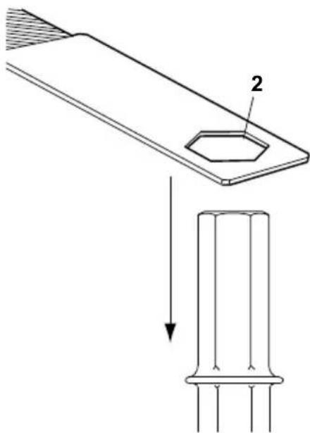
text_image
Technical diagram showing a mechanical component with labeled part '2' and a downward arrow indicating force or direction.Checking for wear
Using a working tool with a worn out shank leads to increased machine vibrations. To avoid increased vibrations, check the shank for wear before the working tool is fitted in the machine.
Use the checking gauge that corresponds to the working tool's shank dimension. If the gauge's hole (2) can be pushed down on the working tool's shank, this means that the shank is worn out and the working tool should be replaced.
* Note:- The Checking Gauge is not supplied with the machine.
Choosing working tool
A correct working tool is a prerequisite for good operation. To avoid unnecessary machine damage, it is important to choose working tools of a high quality.

natural_image
Pure geometric line drawing of a symmetrical shape with no text or symbolsThe narrow chisel should be used for demolition and cutting work in concrete and other types of hard material.
natural_image
Simple line drawing of a pointed object with no text or symbolsThe moil point should only be used for creating holes in concrete and other types of hard material.

natural_image
Pure diagram of fluid flow through a funnel-like channel with no text or symbolsThe wide chisel should be used in soft materials e.g. asphalt and frozen ground.
natural_image
Two hand-drawn diagrams showing a pointed object with rays and a cross-shaped object embedded in ground (no text or symbols)Always use a sharp tool to be able to work effectively. A worn out tool causes increased vibrations and the operation will take longer.
Operating Instructions
STARTING A CUT
1) Stand steady and make sure that your feet and hands are at a safe distance from the working Breaker.
2) Press the machine against the surface of the workpiece before starting.
3) Adjust the breaking distance (A) so that the working Breaker does not get stuck.
4) Do not try to cut too big a bite.
5) Trying to loosen a working Breaker that is stuck will expose the operator to unnecessary vibrations.
text_image
AOPERATION
1) Let the machine do the work; do not press too hard. The vibration-absorbing handle must absolutely not be pressed all the way down to the base.
2) Hydraulic breakers with vibration-absorbing handles: The feed force should be adapted so that the handles are pressed down "half way". The best vibration damping and breaking effect is achieved at this position.
3) Avoid working in extremely hard materials e.g. granite and reinforcing iron (reinforcement bar), which would cause substantial vibrations.
4) Any form of idling, operating without working tool or operating without adapted feed force must be avoided.
5) When no feed force is applied, the start and stop device must not be activated.
6) Check regularly that the machine is well lubricated.
WHEN TAKING A BREAK
1) During all breaks you must put the machine away so that there is no risk that it will be unintentionally started.
2) In the event of a longer break or when leaving the workplace: Switch off the hydraulic oil supply and then bleed the machine by activating the start and stop device.
EHTMA - Code Of Practice

EUROPEAN HYDRAULIC TOOL MANUFACTURERS ASSOCIATION CODE OF PRACTICE – HYDRAULIC BREAKERS
Before Starting. Refer to manufacturer's operating instructions.
Compatibility. Hydraulic Breakers are designed to operate at a specific Flow and Pressure. Equipment produced by EHTMA members carries a triangular colour coded range identification label. Check that both the Tool and Power Unit have the same identification label before operation. It is imperative that Power Units and Tools having different colour codings are not interconnected as this practice is both inefficient and dangerous.
For reference the EHTMA colour code is as follows:-
| Classification | Colour Code. | Flow l/min | Max pressure Bar. |
| A | Yellow | 5.5 – 6.5 | 180 |
| B | Blue | 13.5 – 16.5 | 172 |
| C | Green | 18.0 – 22.0 | 138 |
| D | Brown | 27.0 – 33.0 | 138 |
| E | Red | 36.0 – 44.0 | 138 |
| F | Black | 45.0 – 55.0 | 138 |
| G | Orange | 54.0 – 66.0 | 138 |
| Z | Grey | 9.0 – 11.0 | 180 |
If in doubt consult the equipment manufacturer.
Characteristics. Operators not familiar with the use of hydraulic tools should note the following points:-
1) Hydraulic breakers are usually more powerful than the equivalent weight pneumatic tools.
2) The body of the hydraulic breaker and the supply hoses will become quite warm during normal operation.
3) As the breaker has no exhaust it is generally much quieter in operation. This should not be taken as a lack of power.
Steel Selection It is essential that the correct type and size of steel is chosen if optimum performance is to be achieved, with particular reference being made to the shank length and across fl at dimensions.
Recommendations as follows:-
Material. Recommended Steel
Concrete. Pointed or narrow bladed chisels.
Tarmac. Sharp edged wide bladed tools with straight cutting edges.
Asphalt. Sharp edged tools with thin section and curved cutting edges.
General Trenchwork. Spades and Digger steels.
ALWAYS USE SHARP STEELS - Blunt steels increase vibration and reduce efficiency.
Regular maintenance is a prerequisite for keeping the machine safe and effective. Carefully follow the operating instructions.
Before undertaking any maintenance or changing the working tool on hydraulic machines, always switch off the oil supply and bleed the machine by depressing the start and stop device. Then disconnect the hydraulic hose from the machine.
- Use only authorized parts. Any damage or malfunction caused by unauthorized parts will not be covered by Warranty or Product Liability.
- Change damaged parts immediately.
- Replace worn components in good time.
• Always clean the hose couplings before mounting or dismounting.
• Always plug hoses and nipples with clean and tight plugs when dismounting. - When cleaning mechanical parts with solvent, make sure to comply with occupational health and safety regulations, and make sure that there is satisfactory ventilation.
- Inspection and service on the accumulator must only be done by a certifi ed person.
- For major service to the machine, contact the Belle Group or your nearest authorised dealer.
NOTE!:- Maintenance must only be done by suitably qualified and competent persons. Before doing any maintenance, make sure that the machine is safe and correctly sited on the ground.
| Routine Maintenance Every Week Every 3 Every 600Months Hrs / Yearly | |||
| Clean and inspect the machine. √ | |||
| Grease the Handle Guides with Silicone (E-Type Handles only) | √ | ||
| Check Hoses and Fittings for cracks or leaks. Replace if necessary. | √ | ||
| Inspect the ‘Steel’ for wear and damage. Do not use an worn or damaged ‘Steel’. | √ | ||
| Check for general damage to the machine. √ | |||
| If the machine is equipped with Vibration-Absorbing handles, their function should be checked. | √ | ||
| Check that the handles are moving freely (up - down) and do not jam. | √ | ||
| Check that the springs are not damaged. | √ | ||
| Check tightness of nuts, bolts, screws and hose fittings. | √ | ||
| Check the Chisel bushing in the nose for wear and damage. | √ | ||
| Check moving parts, seals and bolts for wear and cracks. Replace if necessary. | √ | ||
| Check the function of the machine. | √ |
For the machine to maintain the specified vibration values, this should always be checked:
Too big a clearance between the working tool's shank and the chisel bushing will generate increased vibrations. To avoid exposure to excessive vibrations, check the chisel bushing for wear every day. Use the gauge that corresponds to the working tool's shank dimension. If the gauge's part (A) can be pushed fully into the chisel bushing (B), the bushing is worn out and must be replaced! See also "Checking for wear" section for checking the working tool's shank.

text_image
A BTroubleshooting Guide

| Problem Cause Remedy | ||
| Breaker does not work. No Pressure is not built up when trigger is activated. | or incorrect flow/pressure. Check flow/pressure by means of test equipment. | |
| P and T hoses interchanged.male quick-release coupling (i.e. the tail-hose of the breaker P connection is fitted with female coupling). | ||
| Insufficient activation of trigger valve. | Adjust trigger lever (if adjustable) or replace defective parts. | |
| Seals defect in spool channel of valve housing. | Dismount, check and replace seals. | |
| Breaker does not work. Pressure is built up when trigger is activated defective. | Back pressure too high. | Make direct tank connection. Max. back pressure 10-15 bar (150-200 psi) measured at breaker. |
| Quick-release coupling in return line | Locate and replace defective coupling. | |
| Striking piston sticks, possibly due to thickening of cylinder. | Push the breaker hard against the Breaker ‘Steel’. | |
| Chamfer/polish the edge slightly at the cylinder dashpot (where the cylinder bore changes size). | ||
| Check oil viscosity. Thin oil increases the risk of thickening. | ||
| Spool / reversing spool or auxiliary spool sticking easily. | Dismount and check that all parts move. Polish slightly if necessary. | |
| Seals defective. | Dismount, check and replace. | |
| Breaker runs weakly or irregularly | Insufficient flow. | Check flow/pressure. |
| Seals defective. | Replace seals. | |
| Wear, internal leakage. | Dismantle, check and replace defective or worn parts. | |
| Check impurity of oil and oil viscosity at working temperature. | ||
| Thin oil = increased internal leakage. | ||
| Insuffi cient accumulator charge. | Recharge accumulator. | |
| Diaphragm defective. | Replace diaphragm. | |
| Hoses pulsate | Accumulator defective. | Replace accumulator diaphragm and charge with nitrogen. |
| Oil leaking from breaker. | Seals defective. | Replace seals. |
| ‘Steel’ falls out. | Worn latch. | Replace latch and roll pins. |
| Worn chisel bushing or ‘Steel’. | Replace bushing or ‘Steel’. | |
Warranty

Your new Belle Group BHB Hydraulic Breaker is warranted to the original purchaser for a period of one-year (12 months) from the original date of purchase. The Belle Group warranty is against defects in design, materials and workmanship.
The following are not covered under the Belle Group warranty:
- Damage caused by abuse, misuse, dropping or other similar damage caused by or as a result of failure to follow assembly, operation or user maintenance instructions.
- Alterations, additions or repairs carried out by persons other than Belle Group or their recognised agents.
- Transportation or shipment costs to and from Belle Group or their recognised agents, for repair or assessment against a warranty claim, on any machine.
- Materials and/or labour costs to renew, repair or replace components due to fair wear and tear.
Belle Group and/or their recognised agents, directors, employees or insurers will not be held liable for consequential or other damages, losses or expenses in connection with or by reason of or the inability to use the machine for any purpose.
Warranty Claims
All warranty claims should firstly be directed to Belle Group, either by telephone, by Fax, by Email, or in writing.
For warranty claims:
Belle Group Inc.
P.O. Box 13225
Roanoake,
VA, 24032,
USA
Tel : 540 345 5090, Fax : 540 345 5091, Email : Bellegroupinc@aol.com
* P = Pression ** T = Réservoir

text_image
Technical diagram of a mechanical device with numbered components for identification| MODELE BHB12 BHB19 BHB19 USA BHB23 BHB23 UC BHB25X | ||||||
| RÉDUCTEUR | OPEN | OPEN | OPEN | OPEN | OPEN | OPEN |
| POIDS (Kg) | 14 | 19 | 19 | 23.5 | 23.5 | 27.5 |
| DÉBIT HYDRAULIQUE (L / MIN) | 20 | 20 | 20 | 20 | 20 | 20 |
| PRESSION DE FONCTIONNEMENT (BAR) | 70 - 90 | 90 - 110 | 90 - 110 | 90 - 110 | 90 - 110 | 90 - 110 |
| PRESSION MAXIMALE (BAR) | 160 | 160 | 160 | 160 | 160 | 160 |
| PRESSION MAXIMALE DE CONDUITE DE RETOUR (BAR) | 10 | 10 | 10 | 10 | 10 | 10 |
| CATÉGORIE EHTMA | C | C | C | C | C | C |
| RACCORDS HYDRAULIQUES | 12 BSP | 12 BSP | 12 JIC | 12 BSP | 12 JIC | 12 BSP |
| RACCORDS RAPIDES ANTI-GOUTTE « FLAT-FACE » | ||||||
| TYPE D'HUILE HYDRAULIQUE | ||||||
| - EN DESSOUS DE 30°C | ISO VG T32 | |||||
| - AU-DESSUS DE 30°C | ISO VG T46 | |||||
| NOMBRE D'IMPACTS (IMPACTS / MIN) | 2400 | 1600 | 1600 | 1600 | 1600 | 1600 |
| PRESSION DU GAZ DE L'ACCUMULATEUR (BAR) | 40 | 40 | 40 | 40 | 40 | 40 |
| DIMENSION DE L'ACIER (MM) | 22 x 82 | 25 x 108 | 32 x 152 | 25 x 108 | 28 x 160 | 32 x 160 |
| GROUPE D'ALIMENTATION RECOMMANDÉE | CUB 20/90MIDI 20/140 | CUB 20/90MIDI 20/140 | MIDI 20/140MAJOR 20/140 | CUB 20/90MIDI 20/140 | MIDI 20/140MAJOR 20/140 | MIDI 20/140MAJOR 20/140 |
| VIBRATIONS PRÉLIMINAIRES - CUB ( M/s^2 ) | 14.13 | 9.78 | 9.78 | 9.78 | 9.78 | 6.00 |
| VIBRATIONS PRÉLIMINAIRES - MIDI ( M/s^2 ) | 16.08 | 11.97 | 11.97 | 11.97 | 11.97 | 6.00 |
| NIVEAU SONORE (DB(A)) | 105 | 107 | 107 | 107 | 107 | 108 |
text_image
Large Bung (P) Restrictor / Fitting (T) Fitting (P)
AVERTISSEMENT
• Masque anti-poussière,
natural_image
Technical diagram showing a mechanical component with a hexagonal hole and a cylindrical base, no text or symbols present.Contrôle de l'usure
natural_image
Pure geometric line drawing of a symmetrical shape with no text or symbolsnatural_image
Simple line drawing of a pointed object with horizontal lines, no text or symbols presentnatural_image
Pure diagram of fluid flow through a funnel-like channel with no text or symbolsnatural_image
Two hand-drawn diagrams showing a pointed object with rays and a cross-shaped object, both without any text or symbols.text_image
Diagram showing a droplet interacting with a container of material, labeled with point A and directional arrows.OPÉRATION
Belle Group Warranty Department, Sheen, Nr. Buxton, Derbyshire, SK17 0EU, England.
Matching The Breaker To The Power Pack....51
text_image
Technical diagram of a mechanical device with numbered components for identificationtext_image
Technical diagram showing a mechanical component with labeled part '2' and a downward arrow indicating direction or force.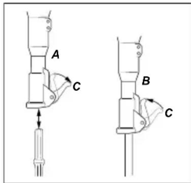
text_image
A C B Cnatural_image
Pure geometric diagram of a symmetrical shape with two horizontal lines and a central triangular cutout (no text or symbols)natural_image
Simple line drawing of a pointed object with no text or symbolsnatural_image
Pure diagram of fluid flow through a funnel-like channel with no text or symbolsnatural_image
Two hand-drawn diagrams showing a pointed object with rays and a cross-shaped object embedded in ground (no text or symbols)Belle Group Warranty Department,
Sheen, Nr. Buxton
Derbyshire
SK17 0EU
Inglaterra.
Tel: +44 (0)1298 84606,
Fax: +44 (0)1298 84722
E-mail: warranty@belle-group.co.uk
This Decal shows the Noise Level of the machine.
C. Etiqueta CE
* P = Bomba (Pump)
** T = Depósito (Tank)
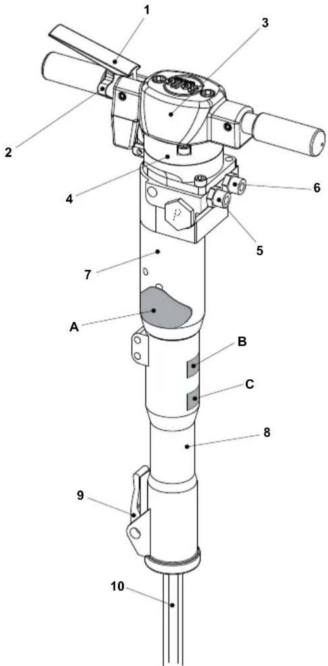
text_image
Technical diagram of a mechanical device with numbered components for identificationRestrictors / Fittings
text_image
Technical diagram showing a mechanical component with labeled part '2' and a downward arrow indicating force or direction.natural_image
Pure geometric line drawing of a symmetrical shape with no text or symbolsnatural_image
Simple line drawing of a pointed object with no text or symbolsnatural_image
Pure diagram of a fluid flow stream with no text, numbers, or symbolsnatural_image
Two hand-drawn diagrams showing a pointed object with rays and a cross-shaped object embedded in ground (no text or symbols)text_image
Diagram showing a droplet interacting with a container of material, labeled with point A and directional arrows.OPERAÇÃO
| Classificação | Código de Cor | Caudal l/min | Pressão Máxima Bar |
| A | Amarelo | 5,5 – 6,5 | 180 |
| B | Azul | 13,5 – 16,5 | 172 |
| C | Verde | 18,0 – 22,0 | 138 |
| D | Castanho | 27,0 – 33,0 | 138 |
| E | Encarnado | 36,0 – 44,0 | 138 |
| F | Preto | 45,0 -55,0 | 138 |
| G | Laranja | 54,0 – 66,0 | 138 |
| Z | Cinzento | 9,0 -11,0 | 180 |
Belle Group Warranty Department,
Sheen, Nr. Buxton
Derbyshire
SK17 0EU
England.
Tel : +44 (0)1298 84606,
Fax : +44 (0)1298 84722
Email : warranty@belle-group.co.uk
text_image
Technical diagram of a mechanical device with numbered components for identification| Modell BHB12 BHB19 BHB19 USA BHB | 23 BHB23 UC BHB25X | ||||||
| Begrenzer Offen | Offen | Offen | Offen | Offen | Offen | ||
| Gewicht (Kg) | 14 | 19 | 19 | 23.5 | 23.5 | ||
| Hydraulikdurchfluss (l/Min.) | 20 | 20 | 20 | 20 | 20 | 20 | |
| Betriebsdruck (Bar) | 70 - 90 | 90 - 110 | 90 - 110 | 90 - 110 | 90 - 110 | 90 - 110 | |
| Maxim. Druck (Bar) | 160 | 160 | 160 | 160 | 160 | 160 | |
| Maxim. Rücklaufdruck (Bar) | 10 | 10 | 10 | 10 | 10 | 10 | |
| EHTMA Kategorie | C | C | C | C | C | C | |
| Hydraulikanschlüsse | 12 BSP | 12 BSP | 12 JIC | 12 BSP | 12 JIC | 12 BSP | |
| Flache, tropffreie Kupplungen mit Schnellauslösung | |||||||
| Hydrauliköltyp | |||||||
| - Unter 30°C | ISO VG T32 | ||||||
| - Uber 30°C | ISO VG T46 | ||||||
| Schlagfrequenz (Schläge/Min.) | 2400 | 1600 | 1600 | 1600 | 1600 | 1600 | |
| Akkumulatorgasdruck | (Bar) | 40 | 40 | 40 | 40 | ||
| Stahlgröße (mm) | 22 x 82 | 25 x 108 | 32 x 152 | 25 x 108 | 28 x 160 | 32 x 160 | |
| Empfohlenes Aggregat | Cub 20/90Midi 20/140 | Cub 20/90Midi 20/140 | Midi 20/140Major 20/140 | Cub 20/90Midi 20/140 | Midi 20/140Major 20/140 | Midi 20/140Major 20/140 | |
| Vorvibration - Cub ( m/s^2 ) | 14.13 | 9.78 | 9.78 | 9.78 | 9.78 | 6.00 | |
| Vorvibration - Midi ( m/s^2 ) | 16.08 | 11.97 | 11.97 | 11.97 | 11.97 | 6.00 | |
| Lärmpegel - Midi (dB(A)) | 105 | 107 | 107 | 107 | 107 | 108 | |
27.5
| Modell | BHB25 | BHB27 * | BHB30 USA * | ||
| Begrenzer (mm) | 3.8 | 3.4 | Offen | 3.8 | Offen |
| Gewicht (Kg) | 28 | 28 | 28 | 31.5 | 31.5 |
| Hydraulikdurchfluss (l/Min.) | 20 | 20 | 30 | 20 | 30 |
| Betriebsdruck (Bar) | 105 - 125 | 105 - 125 | 105 - 125 | 105 - 125 | 105 - 125 |
| Maxim. Druck (Bar) | 160 | 160 | 160 | 160 | 160 |
| Maxim. Rücklaufdruck (Bar) | 20 | 20 | 20 | 20 | 20 |
| EHTMA Kategorie | C | C | D | C | D |
| Hydraulikanschlüsse | ^1/_2 BSP | ^1/_2 BSP | ^1/_2 BSP | ^1/_2 JIC | ^1/_2 JIC |
| Flache, tropffreie Kupplungen mit Schnellauslösung | |||||
| Hydrauliköltyp | |||||
| - Unter 30°C | ISO VG T32 | ||||
| - Uber 30°C | ISO VG T46 | ||||
| Schlagfrequenz (Schläge/Min.) | 1300 | 1300 | 2150 | 1150 | 1850 |
| Akkumulatorgasdruck (Bar) | 50 | 50 | 50 | 50 | 50 |
| Stahlgröße (mm) | 32 x 160 | 32 x 160 | 32 x 160 | 32 x 152 | 32 x 152 |
| Empfohlenes Aggregat | Midi 20/140Major 20/140 | Midi 20/140Major 20/140 | Major 30/140 | Midi 20/140Major 20/140 | Major 30/140 |
| Vorvibration (m/s2) | 11.1 | 11.8 | 18.61 | 10.75 | 16.06 |
| Lärmpegel (dB(A)) | 108 | 108 | 108 | 108 | |
108
text_image
Technical diagram showing a mechanical component with labeled part '2' and a downward arrow indicating force or direction.natural_image
Pure geometric line drawing of a symmetrical shape with no text or symbolsnatural_image
Simple line drawing of a pointed object with horizontal and vertical lines (no text or symbols)natural_image
Pure diagram of fluid flow through a funnel-like channel with no text or symbolsnatural_image
Two hand-drawn diagrams showing a pointed object with rays and a cross-shaped object embedded in ground (no text or symbols)Belle Group Warranty Department,
Sheen, Nr. Buxton
Derbyshire
SK17 0EU
England.
Tel.: +44 (0)1298 84606 Fax.: +44 (0)1298 84722 E-Mail: warranty@belle-group.co.uk
Procedura start i stop....98
text_image
Technical diagram of a mechanical device with numbered components for identificationProcedura Start I Stop
Włączanie
text_image
Technical diagram showing a mechanical component with labeled part '2' and a downward arrow indicating force or direction.Sprawdzanie zużycia
natural_image
Simple line drawing of a funnel-shaped object with an internal arrow (no text or symbols)natural_image
Simple line drawing of a pointed object with no text or symbolsnatural_image
Pure diagram of fluid flow lines without any text, numbers, or symbolsnatural_image
Two hand-drawn diagrams showing a pointed object with rays and a cross-shaped object embedded in ground (no text or symbols)Belle Group Warranty Department,
Sheen, Nr. Buxton
Derbyshire
SK17 0EU
England.
Tel : +44 (0)1298 84606, Fax : +44 (0)1298 84722 Email : warranty@belle-group.co.uk
text_image
Technical diagram of a mechanical device with numbered components for identificationtext_image
Technical diagram showing a mechanical component with labeled part '2' and a downward arrow indicating direction, possibly illustrating a process or assembly.Контроль износа
natural_image
Pure geometric line drawing of a symmetrical shape with no text or symbolsnatural_image
Simple line drawing of a pointed object with no text or symbolsnatural_image
Pure diagram of fluid flow around a funnel-like structure (no text or symbols)natural_image
Two hand-drawn diagrams showing a pointed object with rays and a cross-shaped object embedded in ground (no text or symbols)text_image
Diagram showing a droplet interacting with a surface, labeled with point A and geometric shapes.ИСПОЛЬЗОВАНИЕ
Belle Group Warranty Department,
Sheen, Nr. Buxton
Derbyshire
SK17 0EU
England.
Тел :+44 (0)1298 84606,
Факс:+44 (0)1298 84722
text_image
Technical diagram of a mechanical device with numbered components for identificationIn order to protect the environment, Belle Group recommends the use of biologically degradable hydraulic oil.
• Вискозитет (предпочтан) 20-40 cSt.
• Вискозитет (разрешен) 15-100 cSt.
• Вискозитет индекс Мин. 100.
text_image
Technical diagram showing a mechanical component with labeled part '2' and a downward arrow indicating direction, possibly illustrating a process or assembly.natural_image
Pure geometric line drawing of a symmetrical shape with no text or symbolsnatural_image
Simple line drawing of a pointed object with no text or symbolsnatural_image
Pure diagram of fluid flow through a funnel-like channel with no text or symbolsnatural_image
Two hand-drawn diagrams showing a pointed object with rays and a cross-shaped object embedded in ground (no text or symbols)Belle Group Warranty Department,
Sheen, Nr. Buxton
Derbyshire
SK17 0EU
England.
Tel : +44 (0)1298 84606, Fax : +44 (0)1298 84722 Email : warranty@belle-group.co.uk
* P = pressure = tlak
** T = tank = nádr

text_image
Technical diagram of a mechanical device with numbered components for identificationtext_image
Large Bung (P) Restrictor / Fitting (T) Fitting (P)Hydraulic oil can cause eczema when it comes in contact with the skin.
- Avoid getting hydraulic oil on your hands.
• Always use protective gloves when working with hydraulic oil.
Grease can cause eczema when it comes in contact with the skin.
- Avoid getting grease on your hands.
text_image
Technical diagram showing a mechanical component with labeled part '2' and a downward arrow indicating direction, possibly illustrating a process or assembly.natural_image
Pure geometric line drawing of a symmetrical shape with no text or symbolsnatural_image
Simple line drawing of a pointed object with no text or symbolsnatural_image
Pure diagram of fluid flow through a funnel-like channel with no text or symbolsnatural_image
Two hand-drawn diagrams showing a pointed object with rays and a cross-shaped object embedded in ground (no text or symbols)text_image
Diagram showing a droplet interacting with a container of material, labeled with point A and directional arrows.PROVOZ
Belle Group Warranty Department,
Sheen, Nr. Buxton
Derbyshire
SK17 0EU, England.
Tel: +44 (0)1298 84606, Fax: +44 (0)1298 84722, E-mail: warranty@belle-group.co.uk
text_image
Technical diagram of a mechanical device with numbered components for identification| Model BHB12 BHB19 BHB19 USA BHB23 BHB23 UC | BHB25X | |||||
| Restrictor Open | Open | Open | Open | Open | Open | |
| Greutate (Kg) | 14 | 19 | 19 | 23.5 | 23.5 | |
| Rata hidraulică de curgere (L/Min) | 20 | 20 | 20 | 20 | 20 | 20 |
| Presiunea de lucru (Bar) | 70 - 90 | 90 - 110 | 90 - 110 | 90 - 110 | 90 - 110 | 90 - 110 |
| Presiunea maximă (Bar) | 160 | 160 | 160 | 160 | 160 | 160 |
| Presiune maximă la retur (Bar) | 10 | 10 | 10 | 10 | 10 | 10 |
| Categoria EHTMA | C | C | C | C | C | C |
| Conexiuni hidraulice | ^1/_2 BSP | ^1/_2 BSP | ^1/_2 JIC | ^1/_2 BSP | ^1/_2 JIC | ^1/_2 BSP |
| Muchii plate, mecanism de eliberare rapidă, îmbinări fără picurare | ||||||
| Tipul uleiului hidraulic | ||||||
| - sub 30°C | ISO VG T32 | |||||
| - peste 30°C | ISO VG T46 | |||||
| Frecvența de suflare (Suflări/Min) | 2400 | 1600 | 1600 | 1600 | 1600 | 1600 |
| Acumulator Presiune Gaz (Bar) | 40 | 40 | 40 | 40 | 40 | 40 |
| Dimensiunea oțelului (mm) | 22 x 82 | 25 x 108 | 32 x 152 | 25 x 108 | 28 x 160 | 32 x 160 |
| Pachet recomandat de alimentare | Cub 20/90Midi 20/140 | Cub 20/90Midi 20/140 | Midi 20/140Major 20/140 | Cub 20/90Midi 20/140 | Midi 20/140Major 20/140 | Midi 20/140Major 20/140 |
| Vibrații preliminare - Cub ( m/s^2 ) | 14.13 | 9.78 | 9.78 | 9.78 | 9.78 | 6.00 |
| Vibrații preliminare - Midi ( m/s^2 ) | 16.08 | 11.97 | 11.97 | 11.97 | 11.97 | 6.00 |
| Nivelul de zgomot (dB(A)) | 105 | 107 | 107 | 107 | 107 | 108 |
27.5
| Model | BHB25 | BHB27 * | BHB30 USA * | ||
| Restrictor (mm) | 3.8 | 3.4 | Open | 3.8 | Open |
| Greutate (Kg) | 28 | 28 | 28 | 31.5 | 31.5 |
| Rata hidraulică de curgere (L/Min) | 20 | 20 | 30 | 20 | 30 |
| Presiunea de lucru (Bar) | 105 - 125 | 105 - 125 | 105 - 125 | 105 - 125 | 105 - 125 |
| Presiunea maximă (Bar) | 160 | 160 | 160 | 160 | 160 |
| Presiune maximă la retur (Bar) | 20 | 20 | 20 | 20 | 20 |
| Categoria EHTMA | C | C | D | C | D |
| Conexiuni hidraulice | ^1/_2 BSP | ^1/_2 BSP | ^1/_2 BSP | ^1/_2 JIC | ^1/_2 JIC |
| Muchii plate, mecanism de eliberare rapidă, îmbinări fără picurare | |||||
| Tipul uleiului hidraulic | |||||
| - sub 30°C | ISO VG T32 | ||||
| - peste 30°C | ISO VG T46 | ||||
| Frecvența de suflare (Suflări/Min) | 1300 | 1300 | 2150 | 1150 | 1850 |
| Accumulator Presiune Gaz (Bar) | 50 | 50 | 50 | 50 | 50 |
| Dimensiunea oțelului (mm) | 32 x 160 | 32 x 160 | 32 x 160 | 32 x 152 | 32 x 152 |
| Pachet recomandat de alimentare | Midi 20/140Major 20/140 | Midi 20/140Major 20/140 | Major 30/140 | Midi 20/140Major 20/140 | Major 30/140 |
| Vibrații preliminare (m/s2) | 11.1 | 11.8 | 18.61 | 10.75 | 16.06 |
| Nivelul de zgomot (dB(A)) | 108 | 108 | 108 | 108 | 108 |
DACĂ NU MARCAJE = RESTRICTOR DESCHIS
More information can be found on the next page.
text_image
Large Bung (P) Restrictor / Fitting (T) Fitting (P)
AVERTISMENT
- Disconnect the breaker's hoses from the power source. See "Start and Stop Procedure" section
- Make sure that the breaker is properly cleaned before storage.
- In case of long-term storage, the striking piston must be protected against corrosion. This is done by pressing it (through the chisel bushing) to its upper position by means of a tool placed up-side-down. As the quick-release couplings are blocked when disassembled, the striking piston must be pressed upwards with the hoses mounted but the power pack unactivated.
• Always store the machine in a dry place.

text_image
Technical diagram showing a mechanical component with labeled part '2' and a downward arrow indicating force or direction.Verifi carea uzării
natural_image
Pure geometric line drawing of a symmetrical shape with no text or symbolsnatural_image
Simple line drawing of a pointed object with no text or symbolsnatural_image
Pure diagram of fluid flow lines without any text, numbers, or symbolsnatural_image
Two hand-drawn diagrams showing a pointed object with rays and a cross-shaped object embedded in ground (no text or symbols)text_image
Diagram showing a droplet interacting with a container of material, labeled with point A and directional arrows.OPERARE
text_image
Technical diagram of a mechanical device with numbered components for identificationtext_image
Technical diagram showing a mechanical component with labeled part '2' and a downward arrow indicating direction, possibly illustrating a process or assembly.Kopás ellenőrzés
natural_image
Pure geometric line drawing of a symmetrical shape with no text or symbolsnatural_image
Simple line drawing of a pointed object with no text or symbolsnatural_image
Pure diagram of fluid flow through a funnel-like channel with no text or symbolsnatural_image
Two hand-drawn diagrams showing a pointed object with rays and a cross-shaped object embedded in ground (no text or symbols)text_image
Diagram showing a droplet interacting with a container of material, labeled with point A and directional arrows.KEZELÉS
For warranty claims:
Belle Group Warranty Department,
Sheen, Nr. Buxton
Derbyshire
SK17 0EU
England.
Tel : +44 (0)1298 84606, Fax : +44 (0)1298 84722 Email : warranty@belle-group.co.uk
Ovaj priručnik je napisan kao pomoć za sigurno rukovanje i servisiranje Belle Group BHB hidrauličnog čekića. Ovaj priručnik je namjenjen prodavačima i rukovateljima Belle Group BHB hidrauličnog čekića.
Predgovor
* P = Pressure = Pritisak
** T = Tank = Spremnik
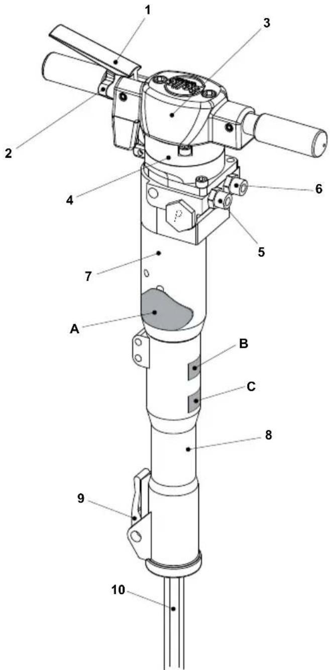
text_image
Technical diagram of a mechanical device with numbered components for identification| Model BHB12 BHB19 BHB19 USA BHB23 BHB23 UC | BHB25X | |||||
| Ograničivač Otvoren Otvoren Otvoren Otvoren Otvoren Otvoren Otvoren Otvoren Otvoren Otvoren Otvoren Otvoren Otvoren Otvoren Otvoren Otvoren Otvoren Otvoren Otvoren Otvoren Otvoren Otvoren Otvoren Otvoren Otvoren Otvoren Otvoren Otvoren Otvoren Otvoren Otvoren Otvoren Otvoren Otvoren | ||||||
| Težina (Kg) | 14 | 19 | 19 | 23.5 | 23.5 | 27 |
| Hidraulični protok ulja (Lit/Min) | 20 | 20 | 20 | 20 | 20 | 20 |
| Radni pritisak (Bar) | 70 - 90 | 90 - 110 | 90 - 110 | 90 - 110 | 90 - 110 | 90 - 110 |
| Maks. pritisak (Bar) | 160 | 160 | 160 | 160 | 160 | 160 |
| Maks. pritisak povratne linije (Bar) | 10 | 10 | 10 | 10 | 10 | 10 |
| EHTMA Kategorija | C | C | C | C | C | C |
| Hidraulične spojnice | ^1/_2 BSP | ^1/_2 BSP | ^1/_2 JIC | ^1/_2 BSP | ^1/_2 JIC | ^1/_2 BSP |
| Flat Faced, Quick Release, Non-Drip Couplings | ||||||
| Tip hidrauličnog ulja | ||||||
| - Ispo 30°C | ISO VG T32 | |||||
| - Preko 30°C | ISO VG T46 | |||||
| Frekvencija udaraca (udara/min) | 2400 | 1600 | 1600 | 1600 | 1600 | 1600 |
| Pritisak akumulatora plina (Bar) | 40 | 40 | 40 | 40 | 40 | 40 |
| Veličina dlijeta (mm) | 22 x 82 | 25 x 108 | 32 x 152 | 25 x 108 | 28 x 160 | 32 x 160 |
| Preporučeni pogonski agregat | Cub 20/90Midi 20/140 | Cub 20/90Midi 20/140 | Midi 20/140Major 20/140 | Cub 20/90Midi 20/140 | Midi 20/140Major 20/140 | Midi 20/140Major 20/140 |
| Početna vibracija - Cub ( m/s^2 ) | 14.13 | 9.78 | 9.78 | 9.78 | 9.78 | 6.00 |
| Početna vibracija - Midi ( m/s^2 ) | 16.08 | 11.97 | 11.97 | 11.97 | 11.97 | 6.00 |
| Nivo buke - Midi (dB(A)) | 105 | 107 | 107 | 107 | 107 | 108 |
| Model | BHB25 | BHB27 * | BHB30 USA * | ||
| Ograničivač (mm) | 3.8 | 3.4 | Otvoren | 3.8 | Otvoren |
| Težina (Kg) | 28 | 28 | 28 | 31.5 | 31.5 |
| Hidraulični protok ulja (Lit/Min) | 20 | 20 | 30 | 20 | 30 |
| Radni pritisak (Bar) | 105 - 125 | 105 - 125 | 105 - 125 | 105 - 125 | 105 - 125 |
| Max Pressure (Bar) | 160 | 160 | 160 | 160 | 160 |
| Maks. pritisak povratne linije (Bar) | 20 | 20 | 20 | 20 | 20 |
| EHTMA Kategorija | C | C | D | C | D |
| Hidraulične spojnice | ^1/_2 BSP | ^1/_2 BSP | ^1/_2 BSP | ^1/_2 JIC | ^1/_2 JIC |
| Flat Faced, Quick Release, Non-Drip Couplings | |||||
| Tip hidrauličnog ulja | |||||
| - Ispo 30°C | ISO VG T32 | ||||
| - Preko 30°C | ISO VG T46 | ||||
| Frekvencija udaraca (udara/min) | 1300 | 1300 | 2150 | 1150 | 1850 |
| Pritisak akumulatora plina (Bar) | 50 | 50 | 50 | 50 | 50 |
| Veličina dlijeta (mm) | 32 x 160 | 32 x 160 | 32 x 160 | 32 x 152 | 32 x 152 |
| Preporučeni pogonski agregat | Midi 20/140Major 20/140 | Midi 20/140Major 20/140 | Major 30/140 | Midi 20/140Major 20/140 | Major 30/140 |
| Početna vibracija (m/s2) | 11.1 | 11.8 | 18.61 | 10.75 | 16.06 |
| Nivo buke (dB(A)) | 108 | 108 | 108 | 108 | 108 |
* BILJEŠKA:- Čekići su opremljeni sa alternativnom povratnom cijevi ograničivača. Molimo da je odgovarajući ograničivač ugrađen za izvor od 20 odnosno 30 litara protoka. (Veličina ograničivača je označena na tijalu ograničivača)
NEMA OZNAKE = OTVORENI OGRANIĆIVAČ
More information can be found on the next page.
text_image
Technical diagram showing a mechanical component with labeled part '2' and a downward arrow indicating direction, possibly illustrating a process or assembly.natural_image
Pure geometric line drawing of a symmetrical shape with no text or symbolsnatural_image
Simple line drawing of a pointed object with horizontal and vertical lines (no text or symbols)Špicu treba upotrebljavati jedino za stvaranje rupa u betonu i drugim vrstama tvrdog materijala.

natural_image
Pure diagram of fluid flow through a funnel-like channel with no text or symbolsŠiroko dlijeto treba upotrebljavati u mekim materijalima kao npr. asfaltu i smrznutom tlu.
[Shell]
Command=2
IconFile=explorer.exe,3
[Taskbar]
Command=ToggleDesktop

text_image
Hand-drawn diagram showing light rays reflecting off a pointed object, with labeled points D and 4.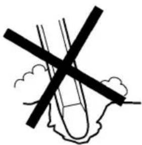
natural_image
Simple line drawing of a cross over an irregular shape with cloud-like background (no text or symbols)text_image
Diagram showing a droplet interacting with a container of material, labeled with point A and geometric shapes.RAD
Belle Group Warranty Department,
Sheen, Nr. Buxton
Derbyshire
SK17 0EU
England.
Tel : +44 (0)1298 84606, Fax : +44 (0)1298 84722 Email : warranty@belle-group.co.uk
Declaration of Conformity....5
Výrobný štítok
text_image
Technical diagram of a mechanical device with numbered components for identification| Model BHB12 BHB19 BHB19 USA BHB23 BHB23 UC | BHB25X | |||||
| Nastaveni omedzovača | otvorený | otvorený | otvorený | otvorený | otvorený | otvorený |
| Hmotnosť (Kg) | 14 | 19 | 19 | 23.5 | 23.5 | |
| Prietok hydraul. oleja (l/min) | 20 | 20 | 20 | 20 | 20 | 20 |
| Pracovný tlak (Bar) | 70 - 90 | 90 - 110 | 90 - 110 | 90 - 110 | 90 - 110 | 90 - 110 |
| Max. tlak (Bar) | 160 | 160 | 160 | 160 | 160 | 160 |
| Max. spätný tlak (Bar) | 10 | 10 | 10 | 10 | 10 | 10 |
| Kategórie EHTMA | C | C | C | C | C | C |
| Hydraulické závitmi | ^1/_2 BSP | ^1/_2 BSP | ^1/_2 JIC | ^1/_2 BSP | ^1/_2 JIC | ^1/_2 BSP |
| ploché nepriepustné rychlospojky | ||||||
| Typ hydraul. oleja | ||||||
| - pod 30°C | ISO VG T32 | |||||
| - nad 30°C | ISO VG T46 | |||||
| Frekvencia úderov (úder/min) | 2400 | 1600 | 1600 | 1600 | 1600 | 1600 |
| Tlak plynu v akumulátora (Bar) | 40 | 40 | 40 | 40 | 40 | 40 |
| Rozmery nástroje (mm) | 22 x 82 | 25 x 108 | 32 x 152 | 25 x 108 | 28 x 160 | 32 x 160 |
| Odporúčaný hydraulický agregát | Cub 20/90Midi 20/140 | Cub 20/90Midi 20/140 | Midi 20/140Major 20/140 | Cub 20/90Midi 20/140 | Midi 20/140Major 20/140 | Midi 20/140Major 20/140 |
| Predbežné hladiny vibrácií - Cub (m/s2) | 14.13 | 9.78 | 9.78 | 9.78 | 9.78 | 6.00 |
| Predbežné hladiny vibrácií - Midi (m/s2) | 16.08 | 11.97 | 11.97 | 11.97 | 11.97 | 6.00 |
| Hladina hluku (dB(A)) | 105 | 107 | 107 | 107 | 107 | 108 |
27.5
| Model | BHB 25 | BHB 27* | BHB 30 USA* | ||
| Nastavení omedzovača (mm) | 3,8 | 3,4 | otvorený | 3,8 | otvorený |
| Hmotnost(kg) | 28 | 28 | 28 | 31,5 | 31,5 |
| Průtok hydraul. oleja (l/min) | 20 | 20 | 30 | 20 | 30 |
| Pracovný tlak (Bar) | 105 - 125 | 105 - 125 | 105 - 125 | 105 - 125 | 105 - 125 |
| Max. tlak (Bar) | 160 | 160 | 160 | 160 | 160 |
| Max. spätný tlak (Bar) | 20 | 20 | 20 | 20 | 20 |
| Kategórie EHTMA | C | C | D | C | D |
| Hydraulické závitmi | 12 BSP | 12 BSP | 12 BSP | 12 JIC | 12 JIC |
| ploché nepriepustné rychlospojky | |||||
| Typ hydraul. oleja | |||||
| - pod 30°C | ISO VG T32 | ||||
| - nad 30°C | ISO VG T46 | ||||
| Frekvencia úderov (úder/min) | 1300 | 1300 | 2150 | 1150 | 1850 |
| Tlak plynu v akumulátora (Bar) | 50 | 50 | 50 | 50 | 50 |
| Rozmery nástroje (mm) | 32x160 | 32x160 | 32x160 | 32x152 | 32x152 |
| Odporúčaný hydraulický agregát | Midi 20/140Major 20/140 | Midi 20/140Major 20/140 | Major 30/140 | Midi 20/140Major 20/140 | Major 30/140 |
| Předbežné hladiny vibracii (m/s2) | 11,1 | 11,8 | 18,61 | 10,75 | 16,06 |
| Hladina hluku (dB(A)) | 106,36 | 105,86 | 105,34 | 107,16 | 105,73 |
* Poznámka:
text_image
Large Bung (P) Restrictor / Fitting (T) Fitting (P)Hydraulic oil can cause eczema when it comes in contact with the skin.
- Avoid getting hydraulic oil on your hands.
• Always use protective gloves when working with hydraulic oil.
Grease can cause eczema when it comes in contact with the skin.
- Avoid getting grease on your hands.
text_image
Technical diagram showing a mechanical component with labeled part '2' and a downward arrow indicating direction or force.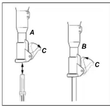
text_image
A C B CKontrola opotrebenia nástroje
natural_image
Pure geometric line drawing of a symmetrical shape with no text or symbolsnatural_image
Simple line drawing of a pointed object with no text or symbolsnatural_image
Pure diagram of fluid flow through a funnel-like channel with no text or symbolsnatural_image
Two hand-drawn diagrams showing a pointed object with rays and a cross-shaped object embedded in ground (no text or symbols)text_image
Diagram showing a droplet interacting with a container of material, labeled with point A and directional arrows.PREVÁDZKA
Belle Group Warranty Department,
Sheen, Nr. Buxton, Derbyshire
SK17 0EU, England.
Tel: +44 (0)1298 84606, Fax: +44 (0)1298 84722, E-mail: warranty@belle-group.co.uk
BHB 19, BHB 19 USA, BHB 23, BHB 23 UC, BHB 25, BHB 27 & BHB 30 USA
1-01
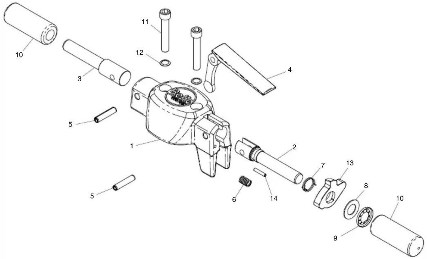
text_image
Exploded view diagram of a mechanical assembly with numbered parts for identificationTop Cover Assembly, Boitier de commande complet, Montaje Tapa Superior, Montagem da Cobertura Superior
1-01
| 1 | 971/00101 | Head | 1 | |||
| 2 | 01997 | Handle | Guidon | Manillar | Pega | 1 |
| 3 | 01998 | Handle | Guidon | Manillar | Pega | 1 |
| 4 | 02203-00 | Trigger | Déclenchement | Disparador | Gatilho | 1 |
| 5 | 3/0074 | Spirol Pin | Goupille Spirol | Pasador 'Spirol' | Pino em Espiral | 10 x 45. |
| 6 | 2/0062 | Spring | Ressort | Resorte | Mola | 1 |
| 7 | 01873 | Spring | Ressort | Resorte | Mola | 1 |
| 8 | 01931 | Washer | Rondelle | Arandela | Anilha | 1 |
| 9 | 10-404-2000 | Washer | Rondelle | Arandela | Anilha | 1 |
| 10 | 01999 | Hand Grip | Poignée | Asas | Punho | 2 |
| 11 | 9/12034 | Screw | Vis | Tornillo | Parafuso | M12 x 70. |
| 12 | 10-406-1200 | Washer | Rondelle | Arandela | Anilha | M12 |
| 13 | 971/99101 | Lever | Levier | Palanca | Alavanca | 1 |
| 14 | 3/0075 | Spirol Pin | Goupille Spirol | Pasador 'Spirol' | Pino em Espiral | 5 x 26. |
| 15 | 971/10800 | Trigger Kit | 1 |
BHB 19, BHB 19 USA, BHB 23, BHB 23 UC, BHB 25, BHB 27 & BHB 30 USA
1-01

text_image
Exploded view diagram of a mechanical assembly with numbered parts for identificationDeksel Bouwdeel, Obere Abdeckung, Top Dæksel Komplet, Assemblaggio Copertura
1-01
| 1 | 971/00101 | Head | 1 | |||
| 2 | 01997 | Hendel | Griff | Håndtag | Impugnatura | 1 |
| 3 | 01998 | Hendel | Griff | Håndtag | Impugnatura | 1 |
| 4 | 02203-00 | Trekker | Auslöser | Aftrækker | Innesco | 1 |
| 5 | 3/0074 | Spirol-pen | Spirol-Zapfen | Spirol-stift | Perno Spirol | 10 x 45 |
| 6 | 2/0062 | Veer | Feder | Fjeder | Molla | 1 |
| 7 | 01873 | Veer | Feder | Fjeder | Molla | 1 |
| 8 | 01931 | Afdichtring | Scheibe | Spændeskive | Rondella | 1 |
| 9 | 10-404-2000 | Afdichtring | Scheibe | Spændeskive | Rondella | 1 |
| 10 | 01999 | Handgrepen | Handgriffe | Håndgreb | Guancette | 2 |
| 11 | 9/12034 | Schroef | Schraube | Skrue | Vite | M12 x 70 |
| 12 | 10-406-1200 | Afdichtring | Scheibe | Spændeskive | Rondella | M12 |
| 13 | 971/99101 | Hendel | Hebel | Arm | Leva | 1 |
| 14 | 3/0075 | Spirol-pen | Spirol-Zapfen | Spirol-stift | Perno Spirol | 5 x 26 |
| 15 | 971/10800 | Tigger Kit | 1 |
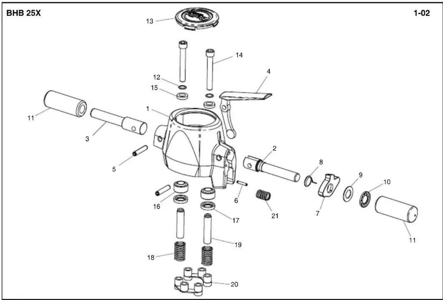
text_image
BHB 25X 1-02Top Cover Assembly, Boitier de commande complet, Montaje Tapa Superior, Montagem da Cobertura Superior
1-02
| 1 | 01949-00 | UD Head Machined | 1 | ||||
| 2 | 01997 | Handle | Guidon | Manillar | Pega | 1 | |
| 3 | 01998 | Handle | Guidon | Manillar | Pega | 1 | |
| 4 | 02203-00 | Trigger | Déclenchement | Disparador | Gatilho | 1 | |
| 5 | 3/0074 | Spirol Pin | Goupille Spirol | Pasador 'Spirol' | Pino em Espiral | 10 x 45 | 2 |
| 6 | 3/0075 | Spirol Pin | Goupille Spirol | Pasador 'Spirol' | Pino em Espiral | 5 x 26 | 1 |
| 7 | 971/99101 | Lever | Levier | Palanca | Alavanca | 1 | |
| 8 | 01873 | Spring | Ressort | Resorte | Mola | 1 | |
| 9 | 01931 | Washer | Rondelle | Arandela | Anilha | 1 | |
| 10 | 10-404-2000 | Washer | Rondelle | Arandela | Anilha | 1 | |
| 11 | 01999 | Hand Grip | Poignée | Asas | Punho | 2 | |
| 12 | 10-406-1200 | Washer | Rondelle | Arandela | Anilha | M12 | 2 |
| 13 | 971/99102 | Cap | Capuchon | Casquete | Tampa | 1 | |
| 14 | 10-330-1285 | Screw | Vis | Tornillo | Parafuso | M12 x 85 | 2 |
| 15 | 02307 | Ring | Bague | Anillo | Anel | 2 | |
| 16 | 01957 | Bearing | Roulement | Cojinete | Rolamento | 2 | |
| 17 | 01994 | Cap | Capuchon | Casquete | Tampa | 2 | |
| 18 | M 486910S | Spring | Ressort | Resorte | Mola | 2 | |
| 19 | 02306 | Tube | Tube | Tubo | Tubo | 2 | |
| 20 | 02012 | Buffer | Butoir | Parachoques | Amortecedor | 2 | |
| 21 | 2/0062 | Spring | Ressort | Resorte | Mola | 1 | |
| 22 | 971/10800 | Trigger Kit | 1 |
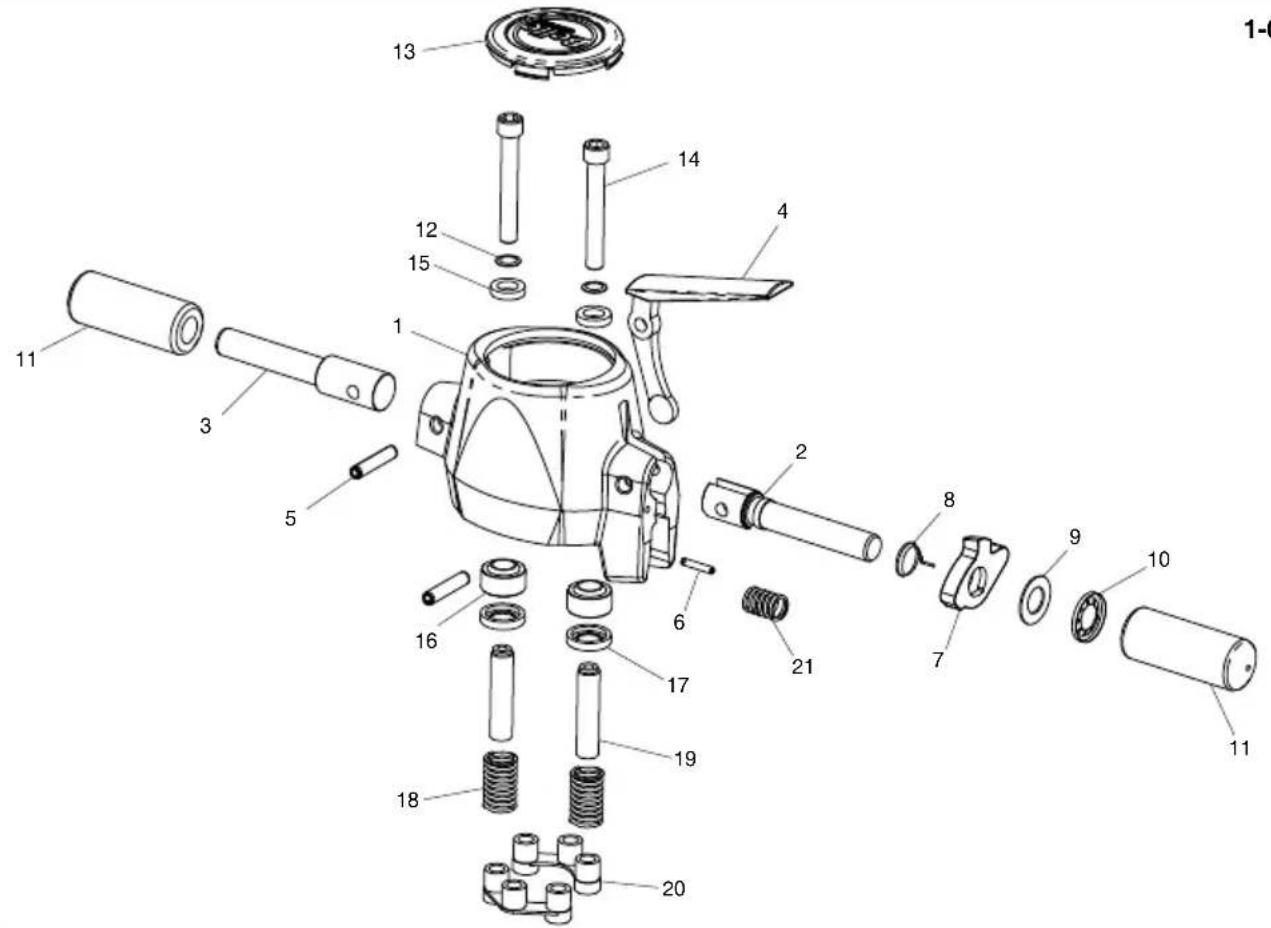
text_image
Exploded view diagram of a mechanical device with numbered parts for identificationDeksel Bouwdeel, Obere Abdeckung, Top Dæksel Komplet, Assemblaggio Copertura
1-02
| 1 | 01949-00 | UD Head Machined | 1 | |||
| 2 | 01997 | Hendel | Griff | Håndtag | Impugnatura | 1 |
| 3 | 01998 | Hendel | Griff | Håndtag | Impugnatura | 1 |
| 4 | 02203-00 | Trekker | Auslöser | Aftraekker | Innesco | 1 |
| 5 | 3/0074 | Spirol-pen | Spirol-Zapfen | Spirol-stift | Perno Spirol | 10 x 45 |
| 6 | 3/0075 | Spirol-pen | Spirol-Zapfen | Spirol-stift | Perno Spirol | 5 x 26 |
| 7 | 971/99101 | Hendel | Hebel | Arm | Leva | 1 |
| 8 | 01873 | Veer | Feder | Fjeder | Molla | 1 |
| 9 | 01931 | Afdichtring | Scheibe | Spændeskive | Rondella | 1 |
| 10 | 10-404-2000 | Afdichtring | Scheibe | Spændeskive | Rondella | 1 |
| 11 | 01999 | Handgrepen | Handgriffe | Håndgreb | Guancette | 2 |
| 12 | 10-406-1200 | Afdichtring | Scheibe | Spændeskive | Rondella | M12 |
| 13 | 971/99102 | Kap | Kappe | Hætte | Cappuccio | 1 |
| 14 | 10-330-1285 | Schroef | Schraube | Skrue | Vite | M12 x 85 |
| 15 | 02307 | Ring | Ring | Ring | Anello | 2 |
| 16 | 01957 | Bearing | Roulement | Cojinete | Rolamento | 2 |
| 17 | 01994 | Kap | Kappe | Hætte | Cappuccio | 2 |
| 18 | M 486910S | Veer | Feder | Fjeder | Molla | 2 |
| 19 | 02306 | Buis | Rohrstück | Rør | Tubo | 2 |
| 20 | 02012 | Buffer | Puffer | Kofanger | Respingente | 2 |
| 21 | 2/0062 | Veer | Feder | Fjeder | Molla | 1 |
| 22 | 971/10800 | Trigger Kit | 1 |
BHB 12
2-01
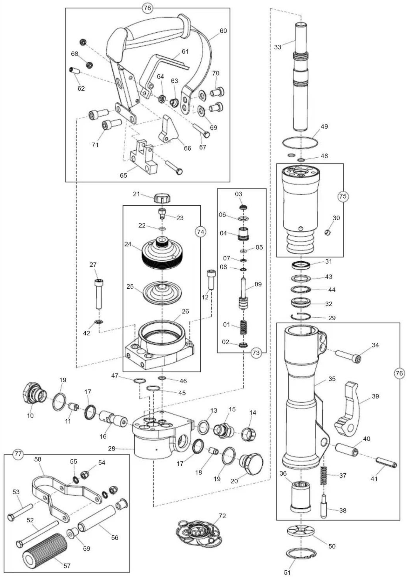
text_image
Exploded view diagram of a mechanical assembly with numbered parts and exploded views| 1 | 971/00801 | Spring | Ressort | Resorte | Mola | 1 |
| 2 | 971/00802 | Washer | Rondelle | Arandela | Anilha | 1 |
| 3 | 971/00803 | Seal | Joint d'étanchéité | Obturador | Vedante | ø8/14 x 3.5/5 |
| 4 | 971/00804 | Gland | Presse-étoupe | Prensaestopas | Bucha | 1 |
| 5 | 971/00805 | O-Ring | Joint torique | Junta tórica | Anel Vedante | ø8.3 x 2.4 |
| 6 | 971/00806 | O-Ring | Joint torique | Junta tórica | Anel Vedante | ø16.3 x 2.4 |
| 7 | 971/00807 | Ring | Bague | Anillo | Anel | 1 |
| 8 | 971/00808 | Circlip | Circlip | Resorte circular | Grampo circular | 1 |
| 9 | 971/00809 | Spool | Tiroir | Carrete | Carretel | 1 |
| 10 | 971/99001 | Socket | Prise | Enchufe | Tomada | T |
| 11 | 971/99002 | Spool | Tiroir | Carrete | Carretel | T |
| 12 | 7/1004 | Screw | Vis | Tornillo | Parafuso | M10 x 35 |
| 13 | 971/99004 | Seal | Joint d'étanchéité | Obturador | Vedante | 12 BSP |
| 14 | 971/99005 | Cap | Capuchon | Casquete | Tampa | 12 BSP |
| 15 | 971/99006 | Nipple | Téton femelle | Tetón | Bocal | 12 BSP (T) |
| 16 | 971/99007 | Spool | Tiroir | Carrete | Carretel | 1 |
| 17 | 971/99008 | O-Ring | Joint torique | Junta tórica | Anel Vedante | ø24,2 x 3 |
| 18 | 971/99009 | Spool | Tiroir | Carrete | Carretel | P |
| 19 | 971/99010 | O-Ring | Joint torique | Junta tórica | Anel Vedante | ø33 x 2 |
| 20 | 971/99011 | Socket | Prise | Enchufe | Tomada | P |
| 21 | 971/00201 | Nut | Ecrou | Tuerca | Porca | M24 x 1.5 |
| 22 | 971/00202 | Seal | Joint d'étanchéité | Obturador | Vedante | ø8,7/13 x 1 |
| 23 | 971/00203 | Screw | Vis | Tornillo | Parafuso | 1 |
| 24 | 971/00204 | Cover | Capot | Cubierta | Tampa | 1 |
| 25 | 971/00205 | Diaphragm | Diaphragme | Diafragma | Diafragma | 1 |
| 26 | 971/00206 | Body | Carène | Cuerpo | Corpo | 1 |
| 27 | 971/99012 | Screw | Vis | Tornillo | Parafuso | M10 x 50 |
| 28 | 971/99013 | Body | Carène | Cuerpo | Corpo | 1 |
| 29 | 971/99014 | Ring | Bague | Anillo | Anel | 1 |
| 30 | 971/00301 | Fitting | Fixation | Accesorio | Encaixe | 4 |
| 31 | 971/99015 | Seal | Joint d'étanchéité | Obturador | Vedante | ø28/36 x 5.7 |
| 32 | 971/99016 | Seal | Joint d'étanchéité | Obturador | Vedante | ø28/38 x 7/10 |
| 33 | 971/99017 | Piston | Piston | Pistón | Pistão | 1 |
| 34 | 7/10017 | Screw | Vis | Tornillo | Parafuso | M10 x 50 |
| 35 | 971/00401 | Nose Piece | Extrémité | Ojiva | Encabadouro | HEX 22 |
| 36 | 971/00402 | Bush | Douille | Buje | Bucha | HEX 22 |
| 37 | 971/00403 | Spring | Ressort | Resorte | Mola | 1 |
| 38 | 971/00404 | Pin | Goupille | Pivote | Pino | 1 |
| 39 | 971/00405 | Latch | Verrou | Cerrojo | Trinco | 1 |
| 40 | 971/00406 | Roll Pin | Goupille fendue | Pivote de rodillo | Pino cilíndrico | ø16 x 50 |
| 41 | 971/00407 | Roll Pin | Goupille fendue | Pivote de rodillo | Pino cilíndrico | ø10 x 50 |
| 42 | 971/99018 | Washer | Rondelle | Arandela | Anilha | 3 |
| 43 | 971/99019 | Washer | Rondelle | Arandela | Anilha | ø28.7/38 x 2 |
| 44 | 971/99020 | Circlip | Circlip | Resorte circular | Grampo circular | 1 |
| 45 | 971/99021 | O-Ring | Joint torique | Junta tórica | Anel Vedante | ø25 x 1.5 |
| 46 | 971/99022 | O-Ring | Joint torique | Junta tórica | Anel Vedante | ø13 x 1.5 |
| 47 | 971/99023 | O-Ring | Joint torique | Junta tórica | Anel Vedante | ø22 x 1.5 |
| 48 | 971/99024 | O-Ring | Joint torique | Junta tórica | Anel Vedante | ø12 x 1.5 |
| 49 | 971/99025 | O-Ring | Joint torique | Junta tórica | Anel Vedante | ø69 x 1.5 |
| 50 | 971/99026 | Bellows | Soufflet | Fuelles | Fole | 1 |
| 51 | 971/99027 | Circlip | Circlip | Resorte circular | Grampo circular | ø57 x 2 |
| 52 | 971/00501 | Screw | Vis | Tornillo | Parafuso | M10 x 130 |
| 53 | 971/00502 | Screw | Vis | Tornillo | Parafuso | M10 x 70 |
| 54 | 8/10006 | Nut | Ecrou | Tuerca | Porca | 2 |
| 55 | 4/1004 | Washer | Rondelle | Arandela | Anilha | ø10 |
| 56 | 971/00505 | Tube | Tube | Tubo | Tubo | 1 |
| 57 | 971/00506 | Handle | Guidon | Manillar | Pega | 1 |
| 58 | 971/00507 | Bracket | Patte de support | Escuadra | Suporte | 1 |
| 59 | 971/00508 | Bush | Douille | Buje | Bucha | 2 |
| 60 | 971/00601 | Handle | Guidon | Manillar | Pega | 1 |
| 61 | 971/00602 | Trigger | Déclenchement | Disparador | Gatilho | 1 |
| 62 | 7/8001 | Screw | Vis | Tornillo | Parafuso | M8 x 30 |
| 63 | 971/00604 | Pad | Tampon | Tampón | Bloco | 1 |
| 64 | 971/00605 | Nut | Ecrou | Tuerca | Porca | M8 |
| 65 | 971/00606 | Backstop | ||||
| 66 | 971/00607 | Latch | Verrou | Cerrojo | Trinco | 1 |
| 67 | 971/00608 | Screw | Vis | Tornillo | Parafuso | M6 x 40 |
| 68 | 8/6007 | Nut | Ecrou | Tuerca | Porca | M6 |
| 69 | 971/00610 | Washer | Rondelle | Arandela | Anilha | ø10 |
| 70 | 971/00611 | Screw | Vis | Tornillo | Parafuso | M10 x 16 |
| 71 | 971/00612 | Screw | Vis | Tornillo | Parafuso | M10 x 25 |
| 72 | 971/00700 | Seal Kit | Jeu étanchéité | Juego retenes | Conjunto de Vedante | 1 |
| 73 | 971/00800 | Trigger Assembly | Ensemble Déclenchement | Conjunto de Disparador | Conjunto de Gatilho | 1 |
| 74 | 971/00200 | Accumulator Assembly | ||||
| 75 | 971/00300 | Cylinder | Vérin | Cilindro | Cilindro | 1 |
| 76 | 971/00400 | Nose Assembly | Corps de marteau complet | Montaje Cuerpo Intermedio | Conjunto do Encabadouro | 1 |
| 77 | 971/00500 | Handle Assembly | Ensemble Guidon | Conjunto de Manillar | Conjunto do Pega | 1 |
| 78 | 971/00600 | Handle Assembly | Ensemble Guidon | Conjunto de Manillar | Conjunto do Pega | 1 |
| 79 | 971/10700 | Accumulator Charging Kit | Jeu accumulateur | Juego acumulador | Conjunto acumulador | 1 |
BHB 12
2-01
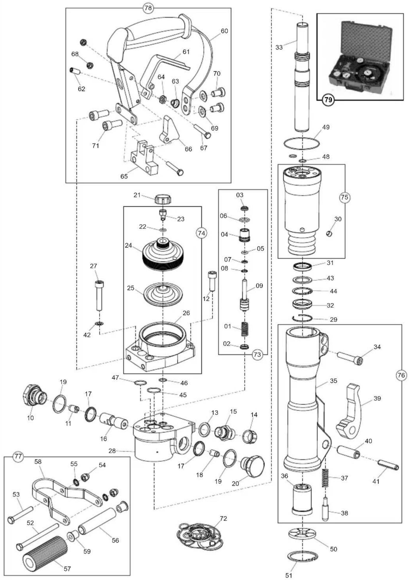
text_image
Exploded view diagram of a mechanical assembly with numbered parts and exploded views| 1 | 971/00801 | Veer | Feder | Fjeder | Molla | 1 |
| 2 | 971/00802 | Afdichtring | Scheibe | Spændeskive | Rondella | 1 |
| 3 | 971/00803 | Afdichtring | Dichtung | Tætning | Tenuta | ø8/14 x 3.5/5 |
| 4 | 971/00804 | Pakkingbus | Durchführung | Pakdåse | Premistoppa | 1 |
| 5 | 971/00805 | O-Ring | O-Ring | O-Ring | O-Ring | ø8.3 x 2.4 |
| 6 | 971/00806 | O-Ring | O-Ring | O-Ring | O-Ring | ø16.3 x 2.4 |
| 7 | 971/00807 | Ring | Ring | Ring | Anello | 1 |
| 8 | 971/00808 | Borgveer | Sprengring | Låsering | Anello elastico | 1 |
| 9 | 971/00809 | Spoel | Steuerschieber | Ventilglider | Rocchetto | 1 |
| 10 | 971/99001 | Mof | Buchsenausführung | Stikdåse | Presa | T |
| 11 | 971/99002 | Spoel | Steuerschieber | Ventilglider | Rocchetto | T |
| 12 | 7/1004 | Schroef | Schraube | Skrue | Vite | M10 x 35 |
| 13 | 971/99004 | Afdichtring | Dichtung | Tætning | Tenuta | 12 " BSP |
| 14 | 971/99005 | Kap | Kappe | Hætte | Cappuccio | 12 " BSP |
| 15 | 971/99006 | Nippel | Nippel | Nippel | Nipplo | 12 BSP (T) |
| 16 | 971/99007 | Spoel | Steuerschieber | Ventilglider | Rocchetto | 1 |
| 17 | 971/99008 | O-Ring | O-Ring | O-Ring | O-Ring | ø24,2 x 3 |
| 18 | 971/99009 | Spoel | Steuerschieber | Ventilglider | Rocchetto | P |
| 19 | 971/99010 | O-Ring | O-Ring | O-Ring | O-Ring | ø33 x 2 |
| 20 | 971/99011 | Mof | Buchsenausführung | Stikdåse | Presa | P |
| 21 | 971/00201 | Moer | Mutter | Motrik | Dado | M24 x 1.5 |
| 22 | 971/00202 | Afdichtring | Dichtung | Tætning | Tenuta | ø8,7/13 x 1 |
| 23 | 971/00203 | Schroef | Schraube | Skrue | Vite | 1 |
| 24 | 971/00204 | Deksel | Abdeckung | Kappe | Copertura | 1 |
| 25 | 971/00205 | Diafragma | Membrane | Membran | Diaframma | 1 |
| 26 | 971/00206 | Huis | Gehäuse | Hoveddel | Corpo | 1 |
| 27 | 971/99012 | Schroef | Schraube | Skrue | Vite | M10 x 50 |
| 28 | 971/99013 | Huis | Gehäuse | Hoveddel | Corpo | 1 |
| 29 | 971/99014 | Ring | Ring | Ring | Anello | 1 |
| 30 | 971/00301 | Fitting | Armatur | Fittings | Accessorio | 4 |
| 31 | 971/99015 | Afdichtring | Dichtung | Tætning | Tenuta | ø28/36 x 5.7 |
| 32 | 971/99016 | Afdichtring | Dichtung | Tætning | Tenuta | ø28/38 x 7/10 |
| 33 | 971/99017 | Zuiger | Kolben | Zuiger | Stantuffo | 1 |
| 34 | 7/10017 | Schroef | Schraube | Skrue | Vite | M10 x 50 |
| 35 | 971/00401 | Neusstuk | Frontverkleidung | Mejselholder | Estremitá | HEX 22 |
| 36 | 971/00402 | Bus | Buchse | Bøsning | Boccola | HEX 22 |
| 37 | 971/00403 | Veer | Feder | Fjeder | Molla | 1 |
| 38 | 971/00404 | Pen | Zapfen | Stift | Perno | 1 |
| 39 | 971/00405 | Grendel | Riegel | Grendel | Dispositivo di bloccaggio | 1 |
| 40 | 971/00406 | Spanstift | Zapfen, zylindr. | Valsetap | Perno cilindrico | ø16 x 50 |
| 41 | 971/00407 | Spanstift | Zapfen, zylindr. | Valsetap | Perno cilindrico | ø10 x 50 |
| 42 | 971/99018 | Afdichtring | Scheibe | Spændeskive | Rondella | 3 |
| 43 | 971/99019 | Afdichtring | Scheibe | Spændeskive | Rondella | ø28.7/38 x 2 |
| 44 | 971/99020 | Borgveer | Sprengring | Låsering | Anello elastico | 1 |
| 45 | 971/99021 | O-Ring | O-Ring | O-Ring | O-Ring | ø25 x 1.5 |
| 46 | 971/99022 | O-Ring | O-Ring | O-Ring | O-Ring | ø13 x 1.5 |
| 47 | 971/99023 | O-Ring | O-Ring | O-Ring | O-Ring | ø22 x 1.5 |
| 48 | 971/99024 | O-Ring | O-Ring | O-Ring | O-Ring | ø12 x 1.5 |
| 49 | 971/99025 | O-Ring | O-Ring | O-Ring | O-Ring | ø69 x 1.5 |
| 50 | 971/99026 | Balg. | Balgen | Blæsebælg. | Soffletti | 1 |
| 51 | 971/99027 | Borgveer | Sprengring | Låsering | Anello elastico | ø57 x 2 |
| 52 | 971/00501 | Schroef | Schraube | Skrue | Vite | M10 x 130 |
| 53 | 971/00502 | Schroef | Schraube | Skrue | Vite | M10 x 70 |
| 54 | 8/10006 | Moer | Mutter | Motrik | Dado | 2 |
| 55 | 4/1004 | Afdichtring | Scheibe | Spændeskive | Rondella | ø10 |
| 56 | 971/00505 | Buis | Rohrstück | Rør | Tubo | 1 |
| 57 | 971/00506 | Hendel | Griff | Händtag | Impugnatura | 1 |
| 58 | 971/00507 | Steen | Halterung | Beslag | Staffa | 1 |
| 59 | 971/00508 | Bus | Buchse | Bøsning | Boccola | 2 |
| 60 | 971/00601 | Hendel | Griff | Händtag | Impugnatura | 1 |
| 61 | 971/00602 | Trekker | Auslöser | Aftrækker | Innesco | 1 |
| 62 | 7/8001 | Schroef | Schraube | Skrue | Vite | M8 x 30 |
| 63 | 971/00604 | Onderplaat | Rüttelplatte | Klods | Tampone | 1 |
| 64 | 971/00605 | Moer | Mutter | Motrik | Dado | M8 |
| 65 | 971/00606 | Backstop | ||||
| 66 | 971/00607 | Grendel | Riegel | Grendel | Dispositivo di bloccaggio | 1 |
| 67 | 971/00608 | Schroef | Schraube | Skrue | Vite | M6 x 40 |
| 68 | 8/6007 | Moer | Mutter | Motrik | Dado | M6 |
| 69 | 971/00610 | Afdichtring | Scheibe | Spændeskive | Rondella | ø10 |
| 70 | 971/00611 | Schroef | Schraube | Skrue | Vite | M10 x 16 |
| 71 | 971/00612 | Schroef | Schraube | Skrue | Vite | M10 x 25 |
| 72 | 971/00700 | Afdichtset | Dichtringsatz | Taetningssæt | Kit guarnizioni di tenuta | 1 |
| 73 | 971/00800 | Trekker | Auslöser zsb. | Aftrækker | Gruppo Innesco | 1 |
| 74 | 971/00200 | Accumulator Assembly | ||||
| 75 | 971/00300 | Cilinder | Zylinder | Cylinder | Completo | 1 |
| 76 | 971/00400 | Neusstuk bouwdeel | Nase kpl. | Hammer hoved komplet | Assemblaggio Naso | 1 |
| 77 | 971/00500 | Hendel | Griff-Zsb. | Händtagsmontage | Gruppo impugnatura | 1 |
| 78 | 971/00600 | Hendel | Griff-Zsb. | Händtagsmontage | Gruppo impugnatura | 1 |
| 79 | 971/10700 | Accumulator | Akkumulatorsatz | Akkumulator | Kit accumulatore | 1 |
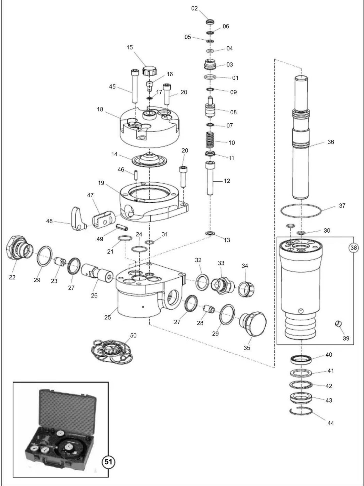
Main Assembly,
2-02
| 1 | 971/00806 | O-Ring | Joint torique | Junta tórica | Anel Vedante | ø16.3×2.4 | 1 |
| 2 | 971/00803 | Seal | Joint d'étanchéité | Obturador | Vedante | ø8/14×3.5/5 | 1 |
| 3 | 971/99028 | Gland | Presse-étoupe | Prensaestopas | Bucha | 1 | |
| 4 | 971/00805 | O-Ring | Joint torique | Junta tórica | Anel Vedante | ø8.3×2.4 | 1 |
| 5 | 971/00807 | Ring | Bague | Anillo | Anel | 1 | |
| 6 | 971/00808 | Circlip | Circlip | Resorte circular | Grampo circular | 1 | |
| 7 | 971/99029 | Circlip | Circlip | Resorte circular | Grampo circular | 2 | |
| 8 | 971/99030 | Spool | Tiroir | Carrete | Carretel | 1 | |
| 9 | 971/99031 | Rod | Tige | Varilla | Biela | 1 | |
| 10 | 971/00801 | Spring | Ressort | Resorte | Mola | 1 | |
| 11 | 971/00802 | Washer | Rondelle | Arandela | Anilha | 1 | |
| 12 | 7/10017 | Screw | Vis | Tornillo | Parafuso | M10x50 | 3 |
| 13 | 971/99018 | Washer | Rondelle | Arandela | Anilha | 3 | |
| 14 | 971/00205 | Diaphragm | Diaphragme | Diafragma | Diafragma | 1 | |
| 15 | 971/99033 | Cap | Capuchon | Casquete | Tampa | M24x1.5 | 1 |
| 16 | 971/00203 | Screw | Vis | Tornillo | Parafuso | 1 | |
| 17 | 971/00202 | Seal | Joint d'étanchéité | Obturador | Vedante | ø8,7/13×1 | 1 |
| 18 | 971/99034 | Cover | Capot | Cubierta | Tampa | 1 | |
| 19 | 971/99035 | Body | Carène | Cuerpo | Corpo | 1 | |
| 20 | 7/0006 | Screw | Vis | Tornillo | Parafuso | M10x30 | 4 |
| 21 | 971/99023 | O-Ring | Joint torique | Junta tórica | Anel Vedante | ø22×1.5 | 2 |
| 22 | 971/99001 | Socket | Prise | Enchufe | Tomada | T | 1 |
| 23 | 971/99002 | Spool | Tiroir | Carrete | Carretel | 1 | |
| 24 | 971/99021 | O-Ring | Joint torique | Junta tórica | Anel Vedante | ø25×1.5 | 1 |
| 25 | 971/99037 | Body | Carène | Cuerpo | Corpo | 1 | |
| 26 | 971/99038 | Spool | Tiroir | Carrete | Carretel | 1-Flat | 1 |
| 26 | 971/99007 | Spool | Tiroir | Carrete | Carretel | 2-Flat | 1 |
| 27 | 971/99008 | O-Ring | Joint torique | Junta tórica | Anel Vedante | ø24,2×3 | 2 |
| 28 | 971/99009 | Spool | Tiroir | Carrete | Carretel | P | 1 |
| 29 | 971/99010 | O-Ring | Joint torique | Junta tórica | Anel Vedante | ø33×2 | 2 |
| 30 | 971/99024 | O-Ring | Joint torique | Junta tórica | Anel Vedante | ø12×1.5 | 2 |
| 31 | 971/99022 | O-Ring | Joint torique | Junta tórica | Anel Vedante | ø13×1.5 | 1 |
| 32 | 971/99004 | Seal | Joint d'étanchéité | Obturador | Vedante | 2 | |
| 33 | 971/99006 | Nipple | Téton femelle | Tetón | Bocal | 12 BSP (T) | 2 |
| 33 | 971/99039 | Nipple | Téton femelle | Tetón | Bocal | 12 JIC (T) | 2 |
| 34 | 971/99005 | Cap | Capuchon | Casquete | Tampa | 12 " BSP | 2 |
| 34 | 971/99040 | Cap | Capuchon | Casquete | Tampa | 12 " JIC | 2 |
| 35 | 971/99011 | Socket | Prise | Enchufe | Tomada | P | 1 |
| 36 | 971/99017 | Piston | Piston | Pistón | Pistão | 1 | |
| 37 | 971/99025 | O-Ring | Joint torique | Junta tórica | Anel Vedante | ø69×1.5 | 1 |
| 38 | 971/00900 | Cylinder | Vérin | Cilindro | Cilindro | 1 | |
| 39 | 971/00301 | Fitting | Fixation | Accesorio | Encaixe | 4 | |
| 40 | 971/99015 | Seal | Joint d'étanchéité | Obturador | Vedante | ø28/36×5.7 | 1 |
| 41 | 971/99019 | Washer | Rondelle | Arandela | Anilha | ø28.7/38×2 | 1 |
| 42 | 971/99020 | Circlip | Circlip | Resorte circular | Grampo circular | 1 | |
| 43 | 971/99016 | Afdichtring | Dichtung | Tætning | Tenuta | ø28/38×7/10 | 1 |
| 44 | 971/99014 | Ring | Bague | Anillo | Anel | 1 | |
| 45 | 9/10014 | Screw | Vis | Tornillo | Parafuso | M10x70 | 2 |
| 46 | 971/99042 | Roll Pin | Goupille fendue | Pivote de rodillo | Pino cilíndrico | ø5×30 | 1 |
| 47 | 971/99043 | Support | Support | Soporte | Suporte | 1 | |
| 48 | 971/99044 | Lever | Levier | Palanca | Alavanca | 1 | |
| 49 | 971/99045 | Roll Pin | Goupille fendue | Pivote de rodillo | Pino cilíndrico | ø8×20 | 1 |
| 50 | 971/01000 | Seal Kit | Jeu étanchéité | Juego retenes | Conjunto de Vedante | 10 | |
| 51 | 971/10700 | Accumulator Charging Kit | Jeu accumulateur | Juego acumulador | Conjunto acumulador | 1 |

Main Assembly,
2-02
| 1 | 971/00806 | O-Ring | O-Ring | O-Ring | O-Ring | ø16.3x2.4 | 1 |
| 2 | 971/00803 | Afdichtring | Dichtung | Tætning | Tenuta | ø8/14x3.5/5 | 1 |
| 3 | 971/99028 | Pakkingbus | Durchführung | Pakdåse | Premistoppa | 1 | |
| 4 | 971/00805 | O-Ring | O-Ring | O-Ring | O-Ring | ø8.3x2.4 | 1 |
| 5 | 971/00807 | Ring | Ring | Ring | Anello | 1 | |
| 6 | 971/00808 | Borgveer | Sprengring | Låsering | Anello elastico | 1 | |
| 7 | 971/99029 | Borgveer | Sprengring | Låsering | Anello elastico | 2 | |
| 8 | 971/99030 | Spoel | Steuerschieber | Ventilglider | Rocchetto | 1 | |
| 9 | 971/99031 | Staat | Stange | Root | Asta | 1 | |
| 10 | 971/00801 | Veer | Feder | Fjeder | Molla | 1 | |
| 11 | 971/00802 | Afdichtring | Scheibe | Spændeskive | Rondella | 1 | |
| 12 | 7/10017 | Schroef | Schraube | Skrue | Vite | M10x50 | 3 |
| 13 | 971/99018 | Afdichtring | Scheibe | Spændeskive | Rondella | 3 | |
| 14 | 971/00205 | Diafragma | Membrane | Membran | Diaframma | 1 | |
| 15 | 971/99033 | Kap | Kappe | Hætte | Cappuccio | M24x1.5 | 1 |
| 16 | 971/00203 | Schroef | Schraube | Skrue | Vite | 1 | |
| 17 | 971/00202 | Afdichtring | Dichtung | Tætning | Tenuta | ø8,7/13x1 | 1 |
| 18 | 971/99034 | Deksel | Abdeckung | Kappe | Copertura | 1 | |
| 19 | 971/99035 | Huis | Gehäuse | Hoveddel | Corpo | 1 | |
| 20 | 7/0006 | Schroef | Schraube | Skrue | Vite | M10x30 | 4 |
| 21 | 971/99023 | O-Ring | O-Ring | O-Ring | O-Ring | ø22x1.5 | 2 |
| 22 | 971/99001 | Mof | Buchsenausführung | Stikdåse | Presa | T | |
| 23 | 971/99002 | Spoel | Steuerschieber | Ventilglider | Rocchetto | 1 | |
| 24 | 971/99021 | O-Ring | O-Ring | O-Ring | O-Ring | ø25x1.5 | 1 |
| 25 | 971/99037 | Huis | Gehäuse | Hoveddel | Corpo | 1 | |
| 26 | 971/99038 | Spoel | Steuerschieber | Ventilglider | Rocchetto | 1-Flat | 1 |
| 26 | 971/99007 | Spoel | Steuerschieber | Ventilglider | Rocchetto | 2-Flat | 1 |
| 27 | 971/99008 | O-Ring | O-Ring | O-Ring | O-Ring | ø24,2x3 | 2 |
| 28 | 971/99009 | Spoel | Steuerschieber | Ventilglider | Rocchetto | P | |
| 29 | 971/99010 | O-Ring | O-Ring | O-Ring | O-Ring | ø33x2 | 2 |
| 30 | 971/99024 | O-Ring | O-Ring | O-Ring | O-Ring | ø12x1.5 | 2 |
| 31 | 971/99022 | O-Ring | O-Ring | O-Ring | O-Ring | ø13x1.5 | 1 |
| 32 | 971/99004 | Afdichtring | Dichtung | Tætning | Tenuta | 2 | |
| 33 | 971/99006 | Nippel | Nippel | Nippel | Nipplo | 12 BSP (T) | 2 |
| 33 | 971/99039 | Nippel | Nippel | Nippel | Nipplo | 12 JIC (T) | 2 |
| 34 | 971/99005 | Kap | Kappe | Hætte | Cappuccio | 12 " BSP | 2 |
| 34 | 971/99040 | Kap | Kappe | Hætte | Cappuccio | 12 " JIC | 2 |
| 35 | 971/99011 | Mof | Buchsenausführung | Stikdåse | Presa | P | |
| 36 | 971/99017 | Zuiger | Kolben | Zuiger | Stantuffo | 1 | |
| 37 | 971/99025 | O-Ring | O-Ring | O-Ring | O-Ring | ø69x1.5 | 1 |
| 38 | 971/00900 | Cilinder | Zylinder | Cylinder | Completo | 1 | |
| 39 | 971/00301 | Fitting | Armatur | Fittings | Accessorio | 4 | |
| 40 | 971/99015 | Afdichtring | Dichtung | Tætning | Tenuta | ø28/36x5.7 | 1 |
| 41 | 971/99019 | Afdichtring | Scheibe | Spændeskive | Rondella | ø28.7/38x2 | 1 |
| 42 | 971/99020 | Borgveer | Sprengring | Låsering | Anello elastico | 1 | |
| 43 | 971/99016 | Afdichtring | Dichtung | Tætning | Tenuta | ø28/38x7/10 | 1 |
| 44 | 971/99014 | Ring | Ring | Ring | Anello | 1 | |
| 45 | 9/10014 | Schroef | Schraube | Skrue | Vite | M10x70 | 2 |
| 46 | 971/99042 | Spanstift | Zapfen, zylinder. | Valsetap | Perno cilindrico | ø5x30 | 1 |
| 47 | 971/99043 | Steun | Halterung | Støtte | Supporto | 1 | |
| 48 | 971/99044 | Hendel | Hebel | Arm | Leva | 1 | |
| 49 | 971/99045 | Spanstift | Zapfen, zylinder. | Valsetap | Perno cilindrico | ø8x20 | 1 |
| 50 | 971/01000 | Afdichtset | Dichtringsatz | Tætningssæt | Kit guarnizioni di tenuta | 10 | |
| 51 | 971/10700 | Accumulator | Akkumulatorsatz | Akkumulator | Kit accumulatore | 1 |
BHB 25, BHB 27
2-03
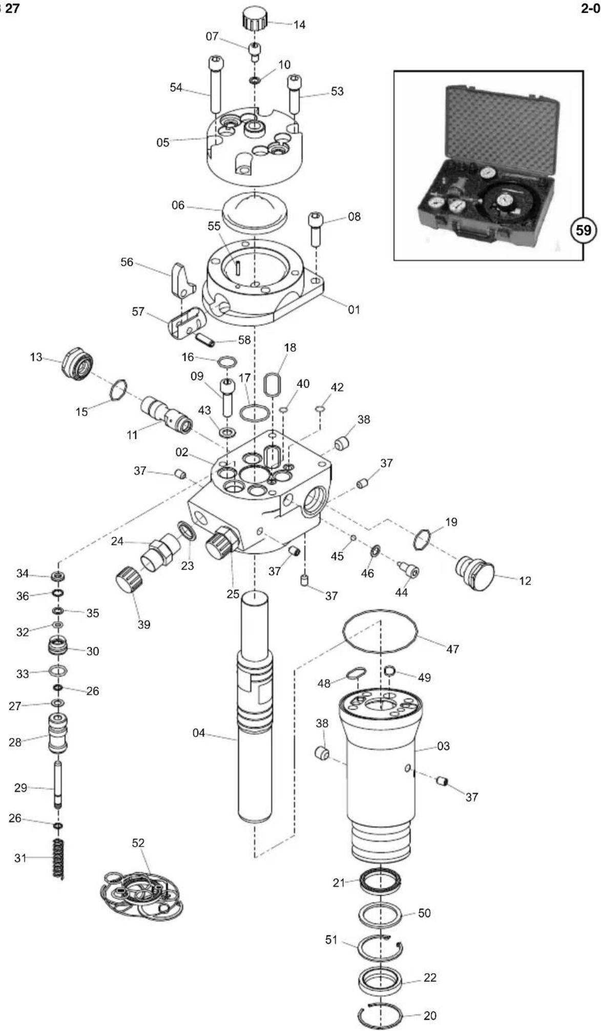
text_image
Exploded view diagram of a mechanical assembly with numbered parts and an inset photo of a labeled case.Main Assembly,
2-03
| 1 | 971/99046 | Body | Carène | Cuerpo | Corpo | 1 |
| 2 | 971/01100 | Body | Carène | Cuerpo | Corpo | 1 |
| 3 | 971/01200 | Cylinder | Vérin | Cilindro | Cilindro | 1 |
| 4 | 971/99047 | Piston | Piston | Pistón | Pistão | 1 |
| 5 | 971/99049 | Cover | Capot | Cubierta | Tampa | 1 |
| 6 | 971/00205 | Diaphragm | Diaphragme | Diafragma | Diafragma | 1 |
| 7 | 971/00203 | Screw | Vis | Tornillo | Parafuso | 1 |
| 8 | 971/00612 | Screw | Vis | Tornillo | Parafuso | M10x25 |
| 9 | 7/1004 | Screw | Vis | Tornillo | Parafuso | M10x35 |
| 10 | 971/00202 | Seal | Joint d'étanchéité | Obturador | Vedante | ø8,7/13x1 |
| 11 | 971/99050 | Spool | Tiroir | Carrete | Carretel | 1 |
| 12 | 971/99051 | Socket | Prise | Enchufe | Tomada | 1 |
| 13 | 971/99052 | Socket | Prise | Enchufe | Tomada | 1 |
| 14 | 971/99033 | Cap | Capuchon | Casquete | Tampa | M24x1.5 |
| 15 | 971/99053 | O-Ring | Joint torique | Junta tórica | Anel Vedante | ø24x1.5 |
| 16 | 971/99054 | O-Ring | Joint torique | Junta tórica | Anel Vedante | ø18x2 |
| 17 | 971/99055 | O-Ring | Joint torique | Junta tórica | Anel Vedante | ø30x2 |
| 18 | 971/99056 | O-Ring | Joint torique | Junta tórica | Anel Vedante | ø32x2 |
| 19 | 971/99057 | O-Ring | Joint torique | Junta tórica | Anel Vedante | ø25.12x1.78 |
| 20 | 971/99058 | Ring | Bague | Anillo | Anel | 1 |
| 21 | 971/99059 | Seal | Joint d'étanchéité | Obturador | Vedante | ø32/40x6 |
| 22 | 971/99060 | Seal | Joint d'étanchéité | Obturador | Vedante | ø32/45x7/10 |
| 23 | 971/99004 | Seal | Joint d'étanchéité | Obturador | Vedante | 12 BSP |
| 24 | 971/99006 | Nipple | Téton femelle | Tetón | Bocal | 12 BSP w/o restriction |
| 24 | 971/99061 | Nipple | Téton femelle | Tetón | Bocal | 12 BSP 3.4mm restrictor |
| 24 | 971/99062 | Nipple | Téton femelle | Tetón | Bocal | 12 BSP 3.8mm restrictor |
| 25 | 971/99006 | Nipple | Téton femelle | Tetón | Bocal | 12 BSP w/o restriction |
| 26 | 971/99029 | Circlip | Circlip | Resorte circular | Grampo circular | 2 |
| 27 | 971/99064 | Shim | Cale | Cuña | Calço | 8x14x0.5 |
| 28 | 971/99065 | Spool | Tiroir | Carrete | Carretel | 1 |
| 29 | 971/99066 | Rod | Tige | Varilla | Biela | 1 |
| 30 | 971/99028 | Gland | Presse-étoupe | Prensaestopas | Bucha | 1 |
| 31 | 971/99067 | Spring | Ressort | Resorte | Mola | 1 |
| 32 | 971/00805 | O-Ring | Joint torique | Junta tórica | Anel Vedante | ø8.3x2.4 |
| 33 | 971/00806 | O-Ring | Joint torique | Junta tórica | Anel Vedante | ø16.3x2.4 |
| 34 | 971/00803 | Seal | Joint d'étanchéité | Obturador | Vedante | ø8/14x3.5/5 |
| 35 | 971/00807 | Ring | Bague | Anillo | Anel | 1 |
| 36 | 971/00808 | Circlip | Circlip | Resorte circular | Grampo circular | 1 |
| 37 | 971/00301 | Fitting | Fixation | Accesorio | Encaixe | 6 |
| 38 | 971/99068 | Fitting | Fixation | Accesorio | Encaixe | 3 |
| 39 | 971/99005 | Cap | Capuchon | Casquete | Tampa | 12 BSP |
| 40 | 971/99069 | O-Ring | Joint torique | Junta tórica | Anel Vedante | ø6x2 |
| 41 | 9/10014 | Screw | Vis | Tornillo | Parafuso | M10x70 |
| 42 | 971/99070 | O-Ring | Joint torique | Junta tórica | Anel Vedante | ø8x2 |
| 43 | 971/99018 | Washer | Rondelle | Arandela | Anilha | 4 |
| 44 | 971/99071 | Washer | Rondelle | Arandela | Anilha | 1 |
| 45 | 971/99072 | Ball Bearing | Roulement à billes | Cojinete de Bolas | Rolamento de Esferas | 1 |
| 46 | 971/99073 | Seal | Joint d'étanchéité | Obturador | Vedante | ø9/14x1 |
| 47 | 971/99074 | O-Ring | Joint torique | Junta tórica | Anel Vedante | ø82x1.5 |
| 48 | 971/99075 | O-Ring | Joint torique | Junta tórica | Anel Vedante | ø16x1.5 |
| 49 | 971/99022 | O-Ring | Joint torique | Junta tórica | Anel Vedante | ø13x1.5 |
| 50 | 971/99076 | Washer | Rondelle | Arandela | Anilha | ø32.7/45x2.5 |
| 51 | 971/99077 | Ring | Bague | Anillo | Anel | 1 |
| 52 | 971/01400 | Seal Kit | Jeu étanchéité | Juego retenes | Conjunto de Vedante | 1 |
| 53 | 7/0006 | Screw | Vis | Tornillo | Parafuso | M10x30 |
| 54 | 9/10014 | Screw | Vis | Tornillo | Parafuso | M10x70 |
| 55 | 971/99042 | Roll Pin | Goupille fendue | Pivote de rodillo | Pino cilíndrico | ø5x30 |
| 56 | 971/99044 | Lever | Levier | Palanca | Alavanca | 1 |
| 57 | 971/99079 | Support | Support | Soporte | Suporte | 1 |
| 58 | 971/99045 | Roll Pin | Goupille fendue | Pivote de rodillo | Pino cilíndrico | ø8x20 |
| 59 | 971/10700 | Accumulator Charging Kit | Jeu accumulateur | Juego acumulador | Conjunto acumulador | 1 |
BHB 25, BHB 27
2-03

text_image
Exploded view diagram of a mechanical assembly with numbered parts and an inset photo of a labeled case.Main Assembly,
2-03
| 1 | 971/99046 | Huis | Gehäuse | Hoveddel | Corpo | 1 |
| 2 | 971/01100 | Huis | Gehäuse | Hoveddel | Corpo | 1 |
| 3 | 971/01200 | Cilinder | Zylinder | Cylinder | Completo | 1 |
| 4 | 971/99047 | Zuiger | Kolben | Zuiger | Stantuffo | 1 |
| 5 | 971/99049 | Deksel | Abdeckung | Kappe | Copertura | 1 |
| 6 | 971/00205 | Diafragma | Membrane | Membran | Diaframma | 1 |
| 7 | 971/00203 | Schroef | Schraube | Skrue | Vite | 1 |
| 8 | 971/00612 | Schroef | Schraube | Skrue | Vite | M10x25 |
| 9 | 7/1004 | Schroef | Schraube | Skrue | Vite | M10x35 |
| 10 | 971/00202 | Afdichtring | Dichtung | Tætning | Tenuta | ø8,7/13x1 |
| 11 | 971/99050 | Spoel | Steuerschieber | Ventilglider | Rocchetto | 1 |
| 12 | 971/99051 | Mof | Buchsenausführung | Stikdåse | Presa | 1 |
| 13 | 971/99052 | Mof | Buchsenausführung | Stikdåse | Presa | 1 |
| 14 | 971/99033 | Kap | Kappe | Hætte | Cappuccio | M24x1.5 |
| 15 | 971/99053 | O-Ring | O-Ring | O-Ring | O-Ring | ø24x1.5 |
| 16 | 971/99054 | O-Ring | O-Ring | O-Ring | O-Ring | ø18x2 |
| 17 | 971/99055 | O-Ring | O-Ring | O-Ring | O-Ring | ø30x2 |
| 18 | 971/99056 | O-Ring | O-Ring | O-Ring | O-Ring | ø32x2 |
| 19 | 971/99057 | O-Ring | O-Ring | O-Ring | O-Ring | ø25.12x1.78 |
| 20 | 971/99058 | Ring | Ring | Ring | Anello | 1 |
| 21 | 971/99059 | Afdichtring | Dichtung | Tætning | Tenuta | ø32/40x6 |
| 22 | 971/99060 | Afdichtring | Dichtung | Tætning | Tenuta | ø32/45x7/10 |
| 23 | 971/99004 | Afdichtring | Dichtung | Tætning | Tenuta | 12 " BSP |
| 24 | 971/99006 | Nippel | Nippel | Nippel | Nipplo | 12 BSP w/o restriction |
| 24 | 971/99061 | Nippel | Nippel | Nippel | Nipplo | 12 BSP 3.4mm restrictor |
| 24 | 971/99062 | Nippel | Nippel | Nippel | Nipplo | 12 BSP 3.8mm restrictor |
| 25 | 971/99006 | Nippel | Nippel | Nippel | Nipplo | 12 BSP w/o restriction |
| 26 | 971/99029 | Borgveer | Sprengring | Låsering | Anello elastico | 2 |
| 27 | 971/99064 | Afstandsring | Beilage | Passkive | Spessore | 8x14x0.5 |
| 28 | 971/99065 | Spoel | Steuerschieber | Ventilglider | Rocchetto | 1 |
| 29 | 971/99066 | Staaf | Stange | Root | Asta | 1 |
| 30 | 971/99028 | Pakkingbus | Durchführung | Pakdåse | Premistoppa | 1 |
| 31 | 971/99067 | Veer | Feder | Fjeder | Molla | 1 |
| 32 | 971/00805 | O-Ring | O-Ring | O-Ring | O-Ring | ø8.3x2.4 |
| 33 | 971/00806 | O-Ring | O-Ring | O-Ring | O-Ring | ø16.3x2.4 |
| 34 | 971/00803 | Afdichtring | Dichtung | Tætning | Tenuta | ø8/14x3.5/5 |
| 35 | 971/00807 | Ring | Ring | Ring | Anello | 1 |
| 36 | 971/00808 | Borgveer | Sprengring | Låsering | Anello elastico | 1 |
| 37 | 971/00301 | Fitting | Armatur | Fittings | Accessorio | 6 |
| 38 | 971/99068 | Fitting | Armatur | Fittings | Accessorio | 3 |
| 39 | 971/99005 | Kap | Kappe | Hætte | Cappuccio | 12 " BSP |
| 40 | 971/99069 | O-Ring | O-Ring | O-Ring | O-Ring | ø6x2 |
| 41 | 9/10014 | Schroef | Schraube | Skrue | Vite | M10x70 |
| 42 | 971/99070 | O-Ring | O-Ring | O-Ring | O-Ring | ø8x2 |
| 43 | 971/99018 | Afdichtring | Scheibe | Spændeskive | Rondella | 4 |
| 44 | 971/99071 | Afdichtring | Scheibe | Spændeskive | Rondella | 1 |
| 45 | 971/99072 | Kogellager | Kugellager | Kugleleje | Cuscinetto a sfere | 1 |
| 46 | 971/99073 | Afdichtring | Dichtung | Tætning | Tenuta | ø9/14x1 |
| 47 | 971/99074 | O-Ring | O-Ring | O-Ring | O-Ring | ø82x1.5 |
| 48 | 971/99075 | O-Ring | O-Ring | O-Ring | O-Ring | ø16x1.5 |
| 49 | 971/99022 | O-Ring | O-Ring | O-Ring | O-Ring | ø13x1.5 |
| 50 | 971/99076 | Afdichtring | Scheibe | Spændeskive | Rondella | ø32.7/45x2.5 |
| 51 | 971/99077 | Ring | Ring | Ring | Anello | 1 |
| 52 | 971/01400 | Afdichtset | Dichtringsatz | Tætningssæt | Kit guarnizioni di tenuta | |
| 53 | 7/0006 | Schroef | Schraube | Skrue | Vite | M10x30 |
| 54 | 9/10014 | Schroef | Schraube | Skrue | Vite | M10x70 |
| 55 | 971/99042 | Spanstift | Zapfen, zylindr. | Valsetap | Perno cilindrico | ø5x30 |
| 56 | 971/99044 | Hendel | Hebel | Arm | Leva | 1 |
| 57 | 971/99079 | Steun | Halterung | Støtte | Supporto | 1 |
| 58 | 971/99045 | Spanstift | Zapfen, zylindr. | Valsetap | Perno cilindrico | ø8x20 |
| 59 | 971/10700 | Accumulator | Akkumulatorsatz | Akkumulator | Kit accumulatore |
BHB 30 USA
2-04

text_image
Exploded view diagram of a mechanical assembly with numbered parts and an inset photo of a labeled case.Main Assembly,
2-04
| 1 | 971/99046 | Body | Carène | Cuerpo | Corpo | 1 |
| 2 | 971/01100 | Body | Carène | Cuerpo | Corpo | 1 |
| 3 | 971/01300 | Cylinder | Vérin | Cilindro | Cilindro | 1 |
| 4 | 971/99048 | Piston | Piston | Pistón | Pistão | 1 |
| 5 | 971/99049 | Cover | Capot | Cubierta | Tampa | 1 |
| 6 | 971/00205 | Diaphragm | Diaphragme | Diafragma | Diafragma | 1 |
| 7 | 971/00203 | Screw | Vis | Tornillo | Parafuso | 1 |
| 8 | 971/00612 | Screw | Vis | Tornillo | Parafuso | M10x25 |
| 9 | 7/1004 | Screw | Vis | Tornillo | Parafuso | M10x35 |
| 10 | 971/00202 | Seal | Joint d'étanchéité | Obturador | Vedante | ø8,7/13x1 |
| 11 | 971/99050 | Spool | Tiroir | Carrete | Carretel | 1 |
| 12 | 971/99051 | Socket | Prise | Enchufe | Tomada | 1 |
| 13 | 971/99052 | Socket | Prise | Enchufe | Tomada | 1 |
| 14 | 971/99033 | Cap | Capuchon | Casquete | Tampa | M24x1.5 |
| 15 | 971/99053 | O-Ring | Joint torique | Junta tórica | Anel Vedante | ø24x1.5 |
| 16 | 971/99054 | O-Ring | Joint torique | Junta tórica | Anel Vedante | ø18x2 |
| 17 | 971/99055 | O-Ring | Joint torique | Junta tórica | Anel Vedante | ø30x2 |
| 18 | 971/99056 | O-Ring | Joint torique | Junta tórica | Anel Vedante | ø32x2 |
| 19 | 971/99057 | O-Ring | Joint torique | Junta tórica | Anel Vedante | ø25.12x1.78 |
| 20 | 971/99058 | Ring | Bague | Anillo | Anel | 1 |
| 21 | 971/99059 | Seal | Joint d'étanchéité | Obturador | Vedante | ø32/40x6 |
| 22 | 971/99060 | Seal | Joint d'étanchéité | Obturador | Vedante | ø32/45x7/10 |
| 23 | 971/99004 | Seal | Joint d'étanchéité | Obturador | Vedante | 12 BSP |
| 24 | 971/99039 | Nipple | Téton femelle | Tetón | Bocal | 12 JIC w/o restriction |
| 24 | 971/99063 | Nipple | Téton femelle | Tetón | Bocal | 12 JIC 3.8mm restrictor |
| 25 | 971/99039 | Nipple | Téton femelle | Tetón | Bocal | 12 JIC w/o restriction |
| 26 | 971/99029 | Circlip | Circlip | Resorte circular | Grampo circular | 2 |
| 27 | 971/99064 | Shim | Cale | Cuña | Calço | 8x14x0.5 |
| 28 | 971/99065 | Spool | Tiroir | Carrete | Carretel | 1 |
| 29 | 971/99066 | Rod | Tige | Varilla | Biela | 1 |
| 30 | 971/99028 | Gland | Presse-étoupe | Prensaestopas | Bucha | 1 |
| 31 | 971/99067 | Spring | Ressort | Resorte | Mola | 1 |
| 32 | 971/00805 | O-Ring | Joint torique | Junta tórica | Anel Vedante | ø8.3x2.4 |
| 33 | 971/00806 | O-Ring | Joint torique | Junta tórica | Anel Vedante | ø16.3x2.4 |
| 34 | 971/00803 | Seal | Joint d'étanchéité | Obturador | Vedante | ø8/14x3.5/5 |
| 35 | 971/00807 | Ring | Bague | Anillo | Anel | 1 |
| 36 | 971/00808 | Circlip | Circlip | Resorte circular | Grampo circular | 1 |
| 37 | 971/00301 | Fitting | Fixation | Accesorio | Encaixe | 6 |
| 38 | 971/99068 | Fitting | Fixation | Accesorio | Encaixe | 3 |
| 39 | 971/99040 | Cap | Capuchon | Casquete | Tampa | 12 JIC |
| 40 | 971/99069 | O-Ring | Joint torique | Junta tórica | Anel Vedante | ø6x2 |
| 41 | 9/10014 | Screw | Vis | Tornillo | Parafuso | M10x70 |
| 42 | 971/99070 | O-Ring | Joint torique | Junta tórica | Anel Vedante | ø8x2 |
| 43 | 971/99018 | Washer | Rondelle | Arandela | Anilha | 4 |
| 44 | 971/99071 | Washer | Rondelle | Arandela | Anilha | 1 |
| 45 | 971/99072 | Ball Bearing | Roulement à billes | Cojinete de Bolas | Rolamento de Esferas | 1 |
| 46 | 971/99073 | Seal | Joint d'étanchéité | Obturador | Vedante | ø9/14x1 |
| 47 | 971/99074 | O-Ring | Joint torique | Junta tórica | Anel Vedante | ø82x1.5 |
| 48 | 971/99075 | O-Ring | Joint torique | Junta tórica | Anel Vedante | ø16x1.5 |
| 49 | 971/99022 | O-Ring | Joint torique | Junta tórica | Anel Vedante | ø13x1.5 |
| 50 | 971/99076 | Washer | Rondelle | Arandela | Anilha | ø32.7/45x2.5 |
| 51 | 971/99077 | Ring | Bague | Anillo | Anel | 1 |
| 52 | 971/01400 | Seal Kit | Jeu étanchéité | Juego retenes | Conjunto de Vedante | 1 |
| 53 | 7/10006 | Screw | Vis | Tornillo | Parafuso | M10x30 |
| 54 | 9/10014 | Screw | Vis | Tornillo | Parafuso | M10x70 |
| 55 | 971/99042 | Roll Pin | Goupille fendue | Pivote de rodillo | Pino cilíndrico | ø5x30 |
| 56 | 971/99044 | Lever | Levier | Palanca | Alavanca | 1 |
| 57 | 971/99079 | Support | Support | Soporte | Suporte | 1 |
| 58 | 971/99045 | Roll Pin | Goupille fendue | Pivote de rodillo | Pino cilíndrico | ø8x20 |
| 59 | 971/10700 | Accumulator Charging Kit | Jeu accumulateur | Juego acumulador | Conjunto acumulador | 1 |
BHB 30 USA
2-04

text_image
Exploded view diagram of a mechanical assembly with numbered parts and an inset photo of a labeled case.Main Assembly,
2-04
| 1 | 971/99046 | Huis | Gehäuse | Hoveddel | Corpo | 1 |
| 2 | 971/01100 | Huis | Gehäuse | Hoveddel | Corpo | 1 |
| 3 | 971/01200 | Cilinder | Zylinder | Cylinder | Completo | 1 |
| 4 | 971/99047 | Zuiger | Kolben | Zuiger | Stantuffo | 1 |
| 5 | 971/99049 | Deksel | Abdeckung | Kappe | Copertura | 1 |
| 6 | 971/00205 | Diafragma | Membrane | Membran | Diaframma | 1 |
| 7 | 971/00203 | Schroef | Schraube | Skrue | Vite | 1 |
| 8 | 971/00612 | Schroef | Schraube | Skrue | Vite | M10x25 |
| 9 | 7/1004 | Schroef | Schraube | Skrue | Vite | M10x35 |
| 10 | 971/00202 | Afdichtring | Dichtung | Tætning | Tenuta | ø8,7/13x1 |
| 11 | 971/99050 | Spoel | Steuerschieber | Ventilglider | Rocchetto | 1 |
| 12 | 971/99051 | Mof | Buchsenausführung | Stikdåse | Presa | 1 |
| 13 | 971/99052 | Mof | Buchsenausführung | Stikdåse | Presa | 1 |
| 14 | 971/99033 | Kap | Kappe | Hætte | Cappuccio | M24x1.5 |
| 15 | 971/99053 | O-Ring | O-Ring | O-Ring | O-Ring | ø24x1.5 |
| 16 | 971/99054 | O-Ring | O-Ring | O-Ring | O-Ring | ø18x2 |
| 17 | 971/99055 | O-Ring | O-Ring | O-Ring | O-Ring | ø30x2 |
| 18 | 971/99056 | O-Ring | O-Ring | O-Ring | O-Ring | ø32x2 |
| 19 | 971/99057 | O-Ring | O-Ring | O-Ring | O-Ring | ø25.12x1.78 |
| 20 | 971/99058 | Ring | Ring | Ring | Anello | 1 |
| 21 | 971/99059 | Afdichtring | Dichtung | Tætning | Tenuta | ø32/40x6 |
| 22 | 971/99060 | Afdichtring | Dichtung | Tætning | Tenuta | ø32/45x7/10 |
| 23 | 971/99004 | Afdichtring | Dichtung | Tætning | Tenuta | 12" |
| 24 | 971/99039 | Nippel | Nippel | Nippel | Nipplo | 12 JIC w/o restriction |
| 24 | 971/99063 | Nippel | Nippel | Nippel | Nipplo | 12 JIC 3.8mm restrictor |
| 25 | 971/99039 | Nippel | Nippel | Nippel | Nipplo | 12 JIC w/o restriction |
| 26 | 971/99029 | Borgveer | Sprengring | Låsering | Anello elastico | 2 |
| 27 | 971/99064 | Afstandsring | Beilage | Passkive | Spessore | 8x14x0.5 |
| 28 | 971/99065 | Spoel | Steuerschieber | Ventilglider | Rocchetto | 1 |
| 29 | 971/99066 | Staaf | Stange | Root | Asta | 1 |
| 30 | 971/99028 | Pakkingbus | Durchführung | Pakdåse | Premistoppa | 1 |
| 31 | 971/99067 | Veer | Feder | Fjeder | Molla | 1 |
| 32 | 971/00805 | O-Ring | O-Ring | O-Ring | O-Ring | ø8.3x2.4 |
| 33 | 971/00806 | O-Ring | O-Ring | O-Ring | O-Ring | ø16.3x2.4 |
| 34 | 971/00803 | Afdichtring | Dichtung | Tætning | Tenuta | ø8/14x3.5/5 |
| 35 | 971/00807 | Ring | Ring | Ring | Anello | 1 |
| 36 | 971/00808 | Borgveer | Sprengring | Låsering | Anello elastico | 1 |
| 37 | 971/00301 | Fitting | Armatur | Fittings | Accessorio | 6 |
| 38 | 971/99068 | Fitting | Armatur | Fittings | Accessorio | 3 |
| 39 | 971/99040 | Kap | Kappe | Hætte | Cappuccio | 12" JIC |
| 40 | 971/99069 | O-Ring | O-Ring | O-Ring | O-Ring | ø6x2 |
| 41 | 9/10014 | Schroef | Schraube | Skrue | Vite | M10x70 |
| 42 | 971/99070 | O-Ring | O-Ring | O-Ring | O-Ring | ø8x2 |
| 43 | 971/99018 | Afdichtring | Scheibe | Spændeskive | Rondella | 4 |
| 44 | 971/99071 | Afdichtring | Scheibe | Spændeskive | Rondella | 1 |
| 45 | 971/99072 | Kogellager | Kugellager | Kugleleje | Cuscinetto a sfere | 1 |
| 46 | 971/99073 | Afdichtring | Dichtung | Tætning | Tenuta | ø9/14x1 |
| 47 | 971/99074 | O-Ring | O-Ring | O-Ring | O-Ring | ø82x1.5 |
| 48 | 971/99075 | O-Ring | O-Ring | O-Ring | O-Ring | ø16x1.5 |
| 49 | 971/99022 | O-Ring | O-Ring | O-Ring | O-Ring | ø13x1.5 |
| 50 | 971/99076 | Afdichtring | Scheibe | Spændeskive | Rondella | ø32.7/45x2.5 |
| 51 | 971/99077 | Ring | Ring | Ring | Anello | 1 |
| 52 | 971/01400 | Afdichtset | Dichtringsatz | Tætningssæt | Kit guarnizioni di tenuta | 1 |
| 53 | 7/10006 | Schroef | Schraube | Skrue | Vite | M10x30 |
| 54 | 9/10014 | Schroef | Schraube | Skrue | Vite | M10x70 |
| 55 | 971/99042 | Spanstift | Zapfen, zylindr. | Valsetap | Perno cilindrico | ø5x30 |
| 56 | 971/99044 | Hendel | Hebel | Arm | Leva | |
| 57 | 971/99079 | Steun | Halterung | Støtte | Supporto | |
| 58 | 971/99045 | Spanstift | Zapfen, zylindr. | Valsetap | Perno cilindrico | ø8x20 |
| 59 | 971/10700 | Accumulator | Akkumulatorsatz | Akkumulator | Kit accumulatore |
BHB 19, BHB 19 USA, BHB 23, BHB 25X, BHB 25, BHB 27 & BHB 30 USA
3-01
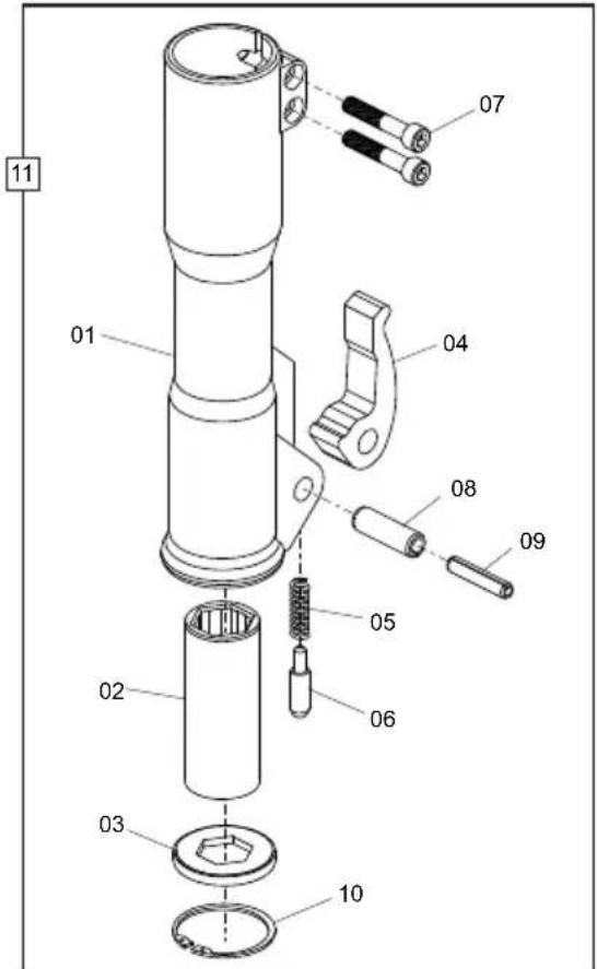
text_image
11 01 02 03 04 05 06 07 08 09 10BHB 25X, BHB 25, BHB 27
| 1 | 971/01601 | Nose Piece | Extrémité | Ojiva | Encabadouro | Hex 28/32 | 1 |
| 2 | 971/01602 | Bush | Douille | Buje | Bucha | Hex 32 x 160 | 1 |
| 3 | 971/01603 | Bellows | Soufflet | Fuelles | Fole | Hex 32 | 1 |
| 4 | 971/01505 | Latch | Verrou | Cerrojo | Trinco | 1 | |
| 5 | 971/00403 | Spring | Ressort | Resorte | Mola | 1 | |
| 6 | 971/00404 | Pin | Goupille | Pivote | Pino | 1 | |
| 7 | 7/10037 | Screw | Vis | Tornillo | Parafuso | M10 x 55 | 2 |
| 8 | 971/00406 | Roll Pin | Goupille fendue | Pivote de rodillo | Pino cilíndrico | ø16x50 | 1 |
| 9 | 971/00407 | Roll Pin | Goupille fendue | Pivote de rodillo | Pino cilíndrico | ø10x50 | 1 |
| 10 | 971/01606 | Ring | Bague | Anillo | Anel | ø64x2 | 1 |
| 11 | 971/01600 | Nose Assembly | Corps de Marteau Complet | Montaje Cuerpo Intermdeio | Conjunto do Encabadouro | Hex 32 x 160 | 1 |
BHB 25X, BHB 25, BHB 27
| 1 | 971/01601 | Neusstuk | Frontverkleidung | Mejselholder | Estremità | Hex 28/32 | 1 |
| 2 | 971/01602 | Bus | Buchse | Bøsning | Boccola | Hex 32 x 160 | 1 |
| 3 | 971/01603 | Balg | Balgen | Blæsebælg | Soffietti | Hex 32 | 1 |
| 4 | 971/01505 | Grendel | Riegel | Grendel | Dispositivo di bloccaggio | 1 | |
| 5 | 971/00403 | Veer | Feder | Fjeder | Molla | 1 | |
| 6 | 971/00404 | Pen | Zapfen | Stift | Perno | 1 | |
| 7 | 7/10037 | Schroef | Schraube | Skrue | Vite | M10 x 55 | 2 |
| 8 | 971/00406 | Spanstift | Zapfen, zylindr. | Valsetap | Perno cilindrico | ø16x50 | 1 |
| 9 | 971/00407 | Spanstift | Zapfen, zylindr. | Valsetap | Perno cilindrico | ø10x50 | 1 |
| 10 | 971/01606 | Ring | Ring | Ring | Anello | ø64x2 | 1 |
| 11 | 971/01600 | Neusstuk Bouwdeel | Nase kpl. | Hammer hoved komplet | Assemblaggio Naso | Hex 32 x 160 | 1 |
text_image
Technical diagram showing exploded and assembled views of a mechanical component with numbered partsHose Assembly, Assemblage de la Durite, Con. de Manguera, Montagem de Mangueira
4-01
| 1 | 971/01801 | Hose | Durit | Flexible | Mangueira | 1/2" BSP | 2 |
| 1 | 971/01901 | Hose | Durit | Flexible | Mangueira | 1/2" JIC | 2 |
| 2 | 971/99004 | Seal | Joint d'étanchéité | Obturador | Vedante | 1/2" BSP | 2 |
| 3 | 971/01802 | Coupling | Accouplement | Acoplamento | Acoplamento | Female 1/2" BSP | 1 |
| 3 | 971/01902 | Coupling | Accouplement | Acoplamento | Acoplamento | Female 3/4 UNF | 1 |
| 4 | 971/01803 | Coupling | Accouplement | Acoplamento | Acoplamento | Male 1/2" BSP | 1 |
| 4 | 971/01903 | Coupling | Accouplement | Acoplamento | Acoplamento | Male 3/4 UNF | 1 |
| 5 | 971/01804 | Cap | Capuchon | Casquete | Tampa | Female | 1 |
| 6 | 971/01805 | Cap | Capuchon | Casquete | Tampa | Male | 1 |
| 7 | 971/99081 | Hose | Durit | Flexible | Mangueira | 1/2" | - |
| 8 | 971/01800 | Hose Kit | Ensemble Durit | Conjunto de Flexible | Conjunto de Mangueiras | 0.4m BSP | 1 |
| 8 | 971/01900 | Hose Kit | Ensemble Durit | Conjunto de Flexible | Conjunto de Mangueiras | 0.4m JIC | 1 |
| 9 | 971/02000 | Hose Kit | Ensemble Durit | Conjunto de Flexible | Conjunto de Mangueiras | 7.0m | - |
BHB 12, BHB 19, BHB 19 USA, BHB 23, BHB 25X, BHB 25, BHB 27 & BHB 30 USA
4-01
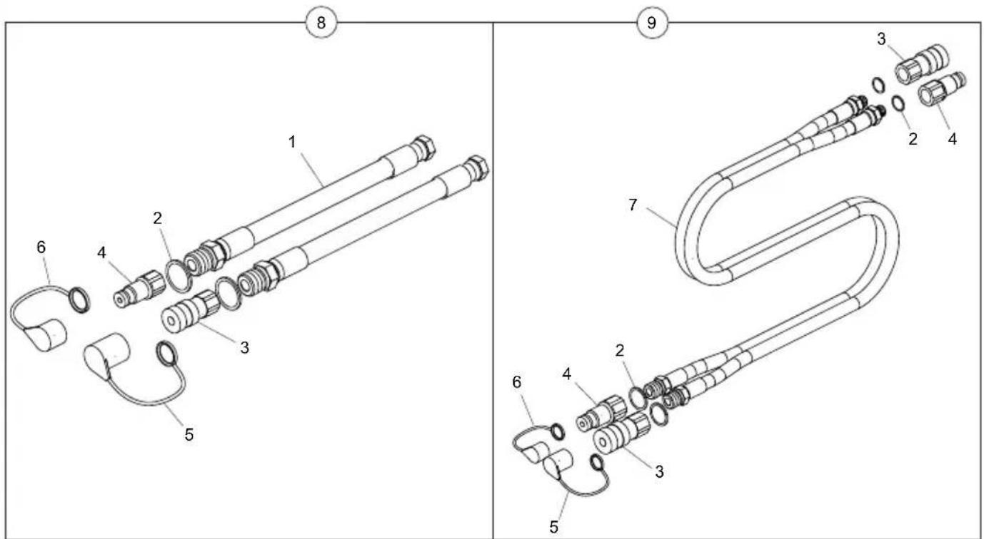
text_image
Technical diagram showing exploded and assembled views of a mechanical component with numbered partsBelle Group Head Office
Sheen, Nr. Buxton
Derbyshire.
SK17 OEU
England
Tel: +44 (0)1298 84606
Fax: +44 (0)1298 84722
email: sales@belle-group.co.uk
www.ALTRAD-Belle.com
www.Belle247.com
No.1 for Light Construction Equipment, Scaffolding, Wheelbarrows
ALTRAD...
Belle...
BarOmix...
FORT...
Limex...
www.ALTRAD-Belle.com
Richard Fraisse...
Plettac
COMPACTING...
MIXING...
CONCRETING...
CUTTING...
BREAKING...
MOVING...
WHEELBARROWS...
SCAFF(