
QCI 8DC - Speaker TANNOY - Free user manual and instructions
Find the device manual for free QCI 8DC TANNOY in PDF.

| Product Type | In-ceiling/in-wall loudspeaker |
| Brand | Tannoy |
| Model | QCI 8DC |
| Category | Installation loudspeaker |
| Speaker Type | Dual 8-inch concentric |
| Technology | Omnimagnet (point source symmetrical dispersion) |
| Cone Material | Polypropylene |
| Surround | High excursion rubber |
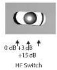
| HF Switch | 3-position variable: 0 dB, +3 dB, +15 dB |
| Trim Ring | Ultra-thin for discreet installation |
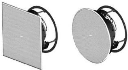
| Included Baffles | Two: square and round |
| Included Grilles | Two: square and round, removable for painting |
| Finish | Semi-matte white |
| Grille Material | Perforated steel with UV-resistant powder coating |
| Dust Protection | Yes (mesh grille) |
| Grille Painting | Possible with supplied protective masks |
| Mounting System | Self-aligning clamps with cable retainers |
| Connections | Screw terminals (positive/negative) at rear |
| Operating Temperature | Up to 45 °C (tropical/moderate climate) |
| Warranty | Limited - see community.musictribe.com |
| Disposal | Recycle at an approved collection point (WEEE) |
| Certifications | WEEE Directive 2012/19/EU |
Frequently Asked Questions - QCI 8DC TANNOY
User questions about QCI 8DC TANNOY
0 question about this device. Answer the ones you know or ask your own.
Ask a new question about this device
Download the instructions for your Speaker in PDF format for free! Find your manual QCI 8DC - TANNOY and take your electronic device back in hand. On this page are published all the documents necessary for the use of your device. QCI 8DC by TANNOY.
USER MANUAL QCI 8DC TANNOY
natural_image
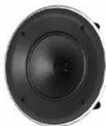
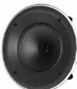
Two black speaker heads with blue acoustic waves, shown from different angles (no text or symbols visible)QCI 3
High-Performance 3" Full-Range In-Ceiling Loudspeaker for Installation Applications
QCI 8DC
High-Performance 8" Dual Concentric In-Ceiling Loudspeaker for Installation Applications
PCI 8DC
Premium 8" Dual Concentric In-Ceiling Loudspeaker for Installation Applications
for use by qualified service personnel only. To reduce the risk of electric shock do not perform any servicing other than that contained in the operation instructions. Repairs have to be performed by qualified service personnel.
-
Read these instructions.
-
Keep these instructions.
-
Heed all warnings.
-
Follow all instructions.
-
Do not use this apparatus near water.
-
Clean only with dry cloth
-
Do not block any ventilation openings. Install in accordance with the manufacturer's instructions.
-
Do not install near any heat sources such as radiators, heat registers, stoves, or other apparatus (including amplifiers) that produce heat.
-
Do not defeat the safety purpose of the polarized or grounding-type plug. A polarized plug has two blades with one wider than the other. A grounding-type plug has two blades and a third grounding prong. The wide blade or the third prong are provided for your safety. If the provided plug does not fit into your outlet, consult an electrician for replacement of the obsolete outlet.
-
Protect the power cord from being walked on or pinched particularly at plugs, convenience receptacles, and the point where they exit from the apparatus.
-
Use only attachments/accessories specified by the manufacturer.

- Use only with the cart, stand, tripod, bracket, or table specified by the manufacturer, or sold with the apparatus. When a cart is n when moving the cart/.
apparatus combination to avoid injury from tip-over.
-
Unplug this app aratus during lightning storms or when unused for long periods of time.
-
Refer all servicing to qualified service personnel. Servicing is required when the apparatus has been damaged in any way, such as power supply cord or plug is damaged, liquid has been spilled or objects have fallen into the apparatus, the apparatus has been exposed to rain or moisture, does not operate normally, or has been dropped.
-
The apparatus shall be connected to a MAINS socket outlet with a protective
earthing connection.
- Where the MAINS plug or an appliance coupler is used as the disconnect device, the disconnect device shall remain readily operable.

- Correct disposal of this product: This symbol indicates that this product must not be disposed of with household waste, according to the WEEE Directive
(2012/19/EU) and your national law. This product should be taken to a collection center licensed for the recycling of waste electrical and electronic equipment (EEE). The mishandling of this type of waste could have a possible negative impact on the environment and human health due to potentially hazardous substances that are generally associated with EEE. At the same time, your cooperation in the correct disposal of this product will contribute to the efficient use of natural resources. For more information about where you can take your waste equipment for recycling, please contact your local city office, or your household waste collection service. 18. Do not install in a confined space, such as a book case or similar unit.
-
Do not place naked flame sources, such as lighted candles, on the apparatus.
-
Please keep the environmental aspects of battery disposal in mind. Batteries must be disposed-of at a battery collection point.
-
This apparatus may be used in tropical and moderate climates up to 45°C.
LEGAL DISCLAIMER
Music Tribe accepts no liability for any loss which may be suffered by any person who relies either wholly or in part upon any description, photograph, or statement contained herein. Technical specifications, appearances and other information are subject to change without notice. All trademarks are the property of their respective owners. Midas, Klark Teknik, Lab Gruppen, Lake, Tannoy, Turbusound, TC Electronic, TC Helican, Behringer, Bugera, Aston Microphones and Coolaudio are trademarks or registered trademarks of Music Tribe Global Brands Ltd. © Music Tribe Global Brands Ltd. 2022 All rights reserved.
LIMITED WARRANTY
For the applicable warranty terms and conditions and additional information regarding Music Tribe's Limited Warranty, please see complete details online at community.musictribe.com/pages/support@warranty.

4 QCI 3/QCI BDC/PCI 8DC
6 QCI 3/QCI BDC/PCI 8DC
DÉNI LÉGAL
BESCHRÄNKTE GARANTIE
8 QCI 3/QCI BDC/PCI 8DC
10 QCI 3/QCI 8DC/PCI 8DC
14 QCI 3/QCI BDC/PCI BDC
Thank you for purchasing this Tannoy high-performance ceiling loudspeaker. This product range is suited for high-level music and speech reinforcement applications requiring exceptional sonic quality with uncompromised reliability.
Features
PCI 8DC
- Premium, high-definition loudspeaker for ceiling installation applications • 8" Dual Concentric driver featuring Tannoy point-source symmetrical dispersion technology • Tulip Waveguide enhances the point-source symmetrical dispersion properties, providing exceptional high frequency clarity and articulation • Blue Kevlar® cone with high-excision, rubber surround for high power handling • 3-way variable HF switch for customised performance preferences
QCI 8DC
- High-performance loudspeaker for ceiling installation applications • 8" Dual Concentric driver featuring Tannoy Omnimagnet technology • Polypropylene cone with rubber surround for high-excision linearity
QCI 3
- High-performance loudspeaker for in-ceiling installation applications • 3* full-range driver with high excursion rubber surround • Glass fibre cone for excellent sound quality and dynamic full range performance • Compact, small footprint design for smaller spaces
Common Features:
- Extremely thin bezel for discreet installation - Includes round and square baffles and grilles for versatile applications - Rigid chassis for improved bass performance and durable application - Integrated construction for easy installation - Semi matt white finish fits unobtrusively in any environment - Powder coated UV resistant perforated steel mesh grille with dust protection - Removable grilles for custom painting - Self-aligning clamp mounting system - Optional Tannoy logo grille badge included
Unpacking
Every Tannoy product and accessory is carefully inspected before packing. After unpacking, please inspect your product to make sure no damage has occurred in transit. In the unlikely event of any damage, would you please notify your dealer immediately and retain your shipping carton, as your dealer may ask you to return the faulty unit to them for inspection.
Safety Notices
Some regional construction codes require the use of a secondary method of securing loudspeakers in ceiling to provide security of a backup support. A secondary support line should be attached from the rear of the product to a source point on the ceiling. Please consult the relevant construction codes in your region.
When using a power driver to install the product it is essential to use the correct torque level settings to avoid over tightening and damage to the ceiling material or clamps.
Recommended torque setting: 1.5 Nm.
Tannoy will not be held responsible for any damages caused by the improper installation of these loudspeakers.
16 QCI 3/QCI 8DC/PCI 8DC
Introducción
18 QCI 3/QCI 8DC/PCI 8DC
Einführung
20 QCI 3/QCI 8DC/PCI 8DC
introduzione
22 QCI 3/QCI 8DC/PCI 8DC
Introduktion
Product Feature Identification
QCI3
Speaker Assembly Speaker Assembly with Square Baffle
natural_image
3D rendering of a speaker or connector component with mounting flanges (no text or symbols visible)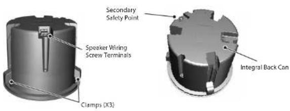
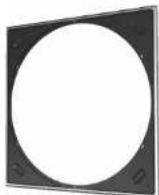
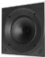
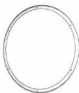
Supplied Items
Circular Grille Assembly
natural_image
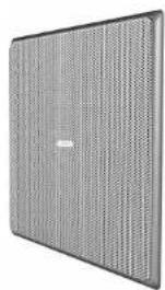
Exterior view of a gray perforated panel with no visible text or symbolsSquare Grille Assembly Square Baffle for Square Grille
25 Quick Start
EN
EN
26 QCI VQCI 8DC/PCI 8DC
Product Feature Identification
QCI 8DC
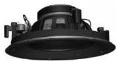
Supplied Accessories
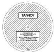
Cutout Installation Template
27Quick Start
EN
28 QCI3/QCI8DC/PCI8DC
Product Feature Identification
PCI 8DC
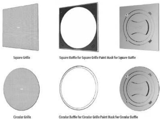
Supplied Items
Square Grille
Square Baffle for Square Grille
Paint Mask for Square Baffle
Circular Grille
Circular Baffle for Circular Grille
Paint Mask for Circular Baffle
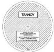
Cutout Installation Template
29 Quick Start
EN
30 QCI 3/QCI 8DC/PCI 8DC
Wiring and Setting Up
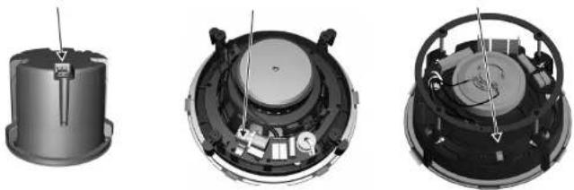
Terminal Connections
- WARNING: To avoid potential damage to your loudspeaker, ensure that the amplifier is switched OFF prior to connecting or disconnecting any cables.
- Before switching the amplifier ON, double check that all connections are secure and that the polarity is correct.
- Note: For each speaker in this series, the correct square or circular baffle has to be fitted before connecting the speaker wiring. (The baffles are fitted from behind, and so the speaker wires cannot be connected while the baffles are being installed.)
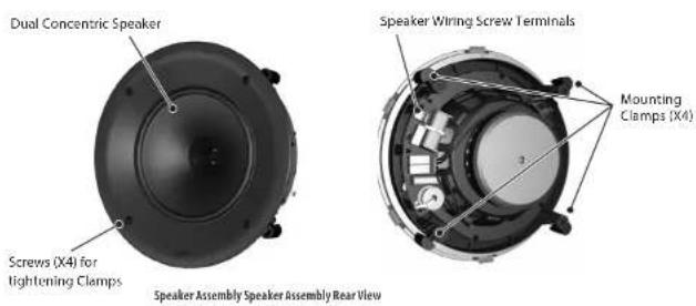
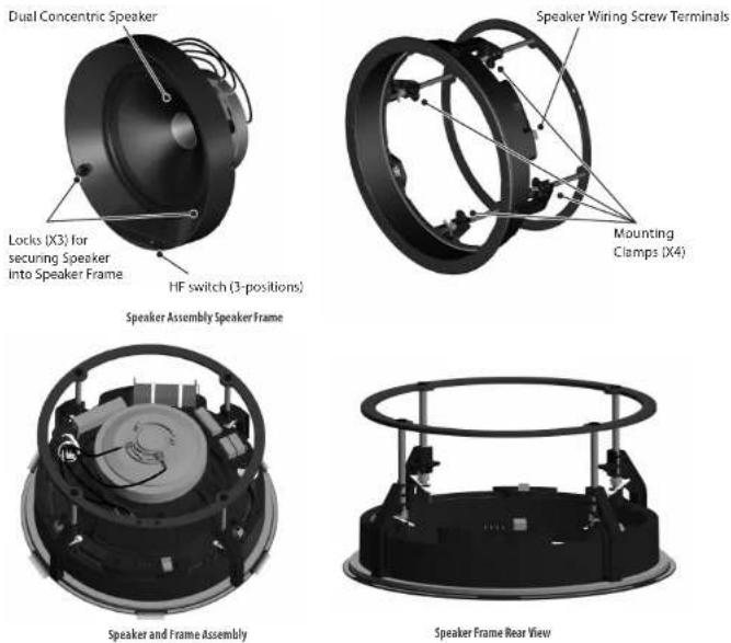
- The two screw terminals on the rear of each speaker are labeled positive (+) and negative (-). These connect respectively to the positive (+) and negative (-) output terminals of your audio power amplifier.
- Strip off approximately 8 mm (1/4") of the outer protective layer of one conductor and twist its inner cores together to prevent shorting from stray wires. Insert the core into the screw terminal while ensuring that correct polarity is maintained. Repeat this for both speaker wires. Tighten the two screws to make a secure connection.
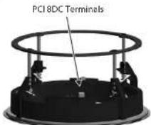
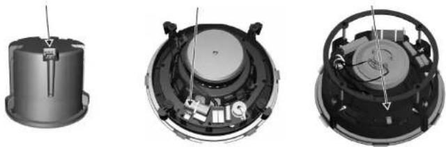
- The screw terminals for the QCI3 and QCI 8DC are located on the rear of each speaker. The screw terminals for the PCI 8DC are located on the speaker frame. The PCI 8DC frame can be preinstalled and wired up, and the speaker assembly added at a later stage.
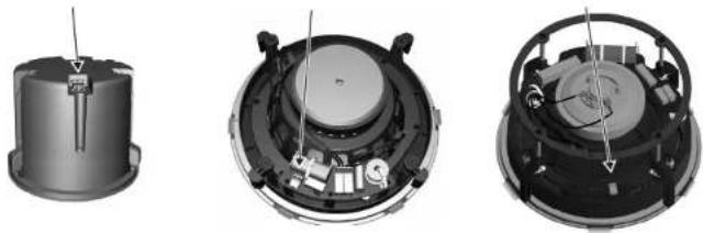
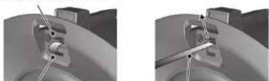
QCI3 Terminals QCI 8DC Terminals PCI 8DC Terminals
natural_image
Three views of a mechanical device showing internal components and assembly (no text or symbols visible)Installation
QCI3
- WARNING: To avoid potential damage to your loudspeaker, ensure that the amplifier is switched OFF prior to connecting or disconnecting any cables.
- The procedure below describes the installation of the QCI3 speaker into a typical stud ceiling or wall with drywall/plasterboard.
- Locate a suitable mounting position for the speaker, using a stud-finder. WARNING: Make sure that there are no power lines, other cables, or plumbing such as water, sewer, gas lines in the chosen cutout location. Also make sure that the location is far enough from the closest wall stud so that the clamping mechanism can operate without interference.
- Carefully mark and cutout a 117 mm (4.6") diameter hole in the drywall/plasterboard, and remove any debris.
- Run the speaker wire from your amplifier to this location, leaving enough slack to allow for the connection.
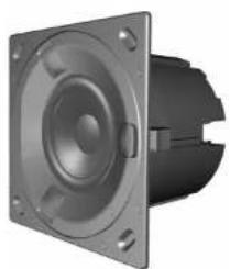
- To use the square speaker grille, push the speaker into the supplied square baffle. The circular grille does not need a circular baffle, as it fits directly over the speaker.
natural_image
3D rendering of a mechanical component with two views showing internal structure, one with a square baffle (no text or symbols)31Quick Start
EN
32 QCI 3/QCI 8DC/PCI 8DC
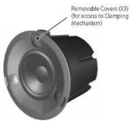
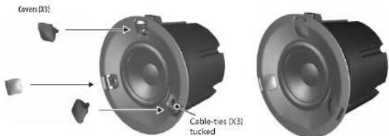
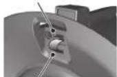
- Pull out the 3 covers from the front of the speaker which hide the clamping system.
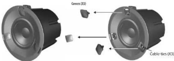
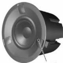
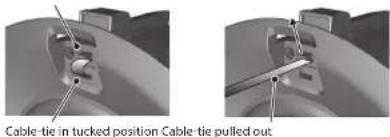
- Each clamp can move up and down in its slot by first pulling out the "cable-ties" from their tucked (stowed) position, and releasing the tab. With the tab held, move each clamp backwards down the slot as far as it will go, so the clamps will be at the rear of the can, and inside the diameter of the cutout hole.
Release Tab Release Tab UP
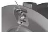

Cable-tie in tucked position Cable-tie pulled out
- Follow the information on the previous pages to connect the speaker wires from your power amplifier to the speaker terminals. Make sure to check that the polarity is correct and that the positive and negative wires are securely and correctly connected.
- Press the speaker (or speaker and square baffle assembly) into the cutout hole in the wall, making sure that the speaker wires are not trapped.
- Pull the clamp cable-ties forward as far as they will go. This will move the clamps forward and secure the speaker to the wall.
33QuickStart
- CAUTION: do not cut off the excess cable-tie length, or the clamps can no longer be reused. Instead, tuck the excess length back into the slots and then re-install the three covers.
- To remove the speaker at any time, remove the three covers, pull the cable-ties out of their tucked position, and then press the tabs, and this will allow you to pull the speaker forwards and out of the hole.
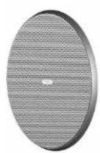
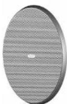
- Install the circular grille by pressing it over the speaker. Small magnets hold it in place.
natural_image
Close-up of a mechanical component with a speaker grille and mounting holes (no visible text or symbols)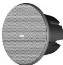
natural_image
Close-up of a black and white electronic speaker with a mesh grille (no visible text or symbols)34 QCIVQC 8DC/PCI8DC
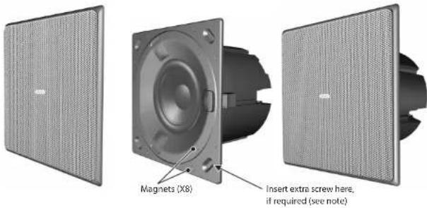
- Alternatively, install the square grille by pressing it over the square baffle. Small magnets in the speaker surround and the square baffle hold it in place.
Note: After installation, if the square baffle does not press flat against the drywall, insert a 12 " long screw in the oval depression in each corner of the baffle, and hand-tighten until the baffle is flat against the drywall.
35Quick Start
EN
INSTALLATION
QCI 8DC
- WARNING: To avoid potential damage to your loudspeaker, ensure that the amplifier is switched OFF prior to connecting or disconnecting any cables.
- The procedure below describes the installation of the speaker into a typical stud ceiling or wall with drywall/plasterboard.
- Locate a suitable mounting position for the speaker, using a stud-finder. WARNING: Make sure that there are no power lines, other cables, or plumbing such as water, sewer, gas lines in the chosen cutout location. Also make sure that the location is far enough from the closest wall stud so that the clamping mechanism can operate without interference.
- Use the supplied cutout template as a guide, and cut out a circular hole in the drywall/plasterboard. Remove any debris from the hole. Use a suitable adhesive in the local area inside the hole to seal the drywall to the studs and joists, to prevent ceiling buzzing.
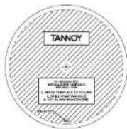
Cutout Installation Template
- Run the speaker wire from your amplifier to this location, leaving enough slack to allow for the connection.
36 QCI 3/QO 8DC/PCI 8DC
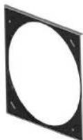
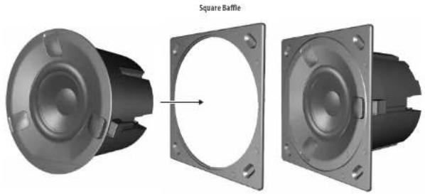
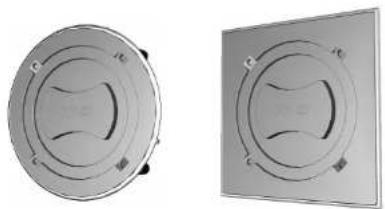
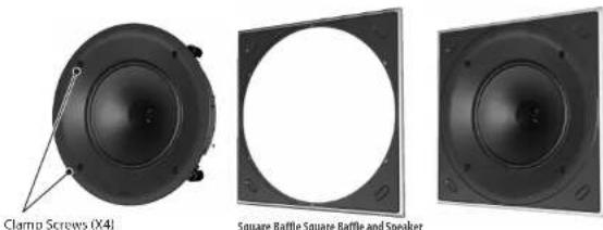
- To use the square speaker grille, first move the mounting clamps out of the way by undoing the four screws accessible from the front of the speaker. Remove the backing from the strips of double-sided tape, and push the speaker into the supplied square baffle.

- If you want to use the circular speaker grille, install the supplied circular baffle instead.
Circular Baffle Circular Baffle and Speaker

- Follow the information on the previous pages to connect the speaker wires from your power amplifier to the speaker terminals. Make sure to check that the polarity is correct and that the positive and negative wires are securely and correctly connected.
- Make sure that the clamps are all in their rest position, then press the speaker/baffle assembly into the cutout hole in the wall, making sure that the speaker wires are not trapped.
37Quick Start
- Tighten the four screws accessible from the front of the speaker, until all four clamps are holding the speaker in place. As the screws are tightened, the clamps rotate out of their rest position and clamp to the drywall/plasterboard.
Note: After installation, if the square baffle does not press flat against the drywall, insert a 1/2" long screw in the oval depression in each corner of the baffle, and hand-tighten until the baffle is flat against the drywall.
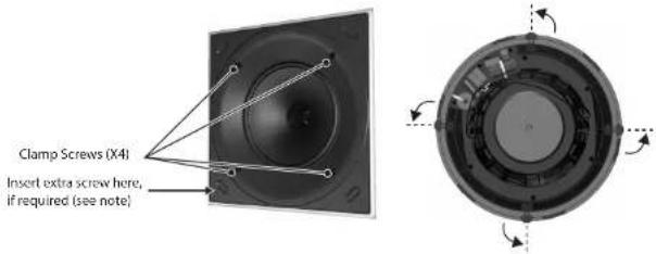
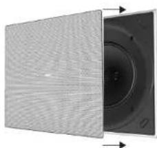
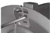
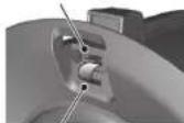
- Install the square grille by pressing it into the square baffle. Small magnets hold it in place.
natural_image
Close-up of a textured panel with a circular component on the right side, showing directional arrows (no text or symbols)
38 QCI 3/QCI 8DC/PCI 8DC
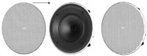
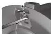
- Alternatively, Install the circular grille by pressing it into the circular baffle. Small magnets hold it in place.
natural_image
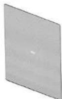
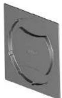
Three circular speaker covers showing different sizes and top views (no text or symbols)- The grilles may be painted to match the decor, before they are fitted onto the speaker baffle.
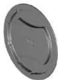
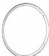
- Use the supplied square or circular masks to help protect the speaker cones when painting.
natural_image
Two circular mechanical components with internal curved features, shown from different angles (no text or symbols visible)Painting Masks in Place
39 Quick Start
EN
INSTALLATION
PCI 8DC
-
WARNING: To avoid potential damage to your loudspeaker, ensure that the amplifier is switched OFF prior to connecting or disconnecting any cables.
-
The procedure below describes the installation of the speaker into a typical stud ceiling with drywall/plasterboard. The PCI 8DC speaker frame is installed and wired, then the speaker assembly can be added later.
-
Locate a suitable mounting position for the speaker, using a stud-finder. WARNING: Make sure that there are no power lines, other cables, or plumbing such as water, sewer, gas lines in the chosen cutout location. Also make sure that the location is far enough from the closest wall stud so that the clamping mechanism can operate without interference.
-
Use the supplied cutout template as a guide, and cut out a circular hole in the drywall/plasterboard. Remove any debris from the hole. Use a suitable adhesive in the local area inside the hole to seal the drywall to the studs and joists, to prevent ceiling buzzing.

Cutout Installation Template
- Run the speaker wire from your amplifier to this location, leaving enough slack to allow for the connection.
40 QQ 3/QC BDC/PCI BDC
- To use the square speaker grille, first move the mounting clamps out of the way as described in step 9 below. Remove the backing from the strips of double-sided tape, and push the speaker frame into the supplied square baffle.
natural_image
Two views of a mechanical component with circular flanges, one showing internal structure and the other showing front view (no text or symbols)
natural_image
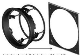
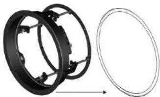
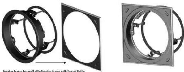
Mechanical component with circular flange and mounting holes (no text or symbols visible)- To use the circular speaker grille, push the speaker frame into the supplied circular baffle instead.
natural_image
Mechanical assembly diagram showing two circular components with internal brackets and a separate wireframe outline (no text or symbols)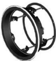
Speaker Frame Circular Baffle Speaker Frame with Circular Baffle
41Quick Start
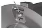
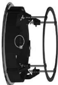
- Follow the information on the previous pages to connect the speaker wires from your power amplifier to the speaker terminals on the speaker frame. Make sure to check that the polarity is correct and that the positive and negative wires are securely and correctly connected. Secure the speaker wiring to the rear ring of the frame with tie-wraps to prevent movement.
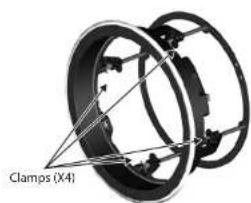
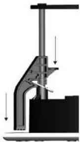
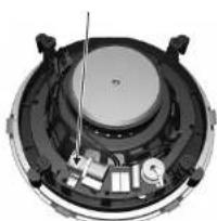
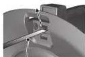
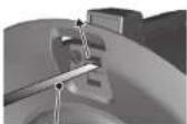
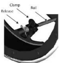
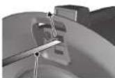
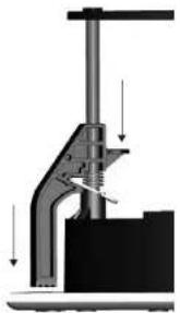
- Carefully press the speaker frame into the cutout hole, making sure the speaker wires are not pinched. Reach inside the frame and rotate the clamps outwards and pull the clamps forward on their rails to secure the speaker frame to the drywall/plasterboard. To remove the speaker frame from the hole, press the release tabs and push the clamps back.


natural_image
Mechanical assembly diagram showing a clamping tool with downward force arrows (no text or labels)EN
42 QCI 3/QCI 8DC/PCI 8DC42
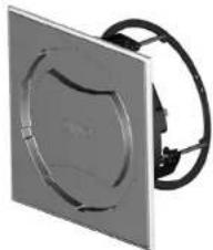
- Use the supplied square or circular masks to help protect the speaker cones when painting.
natural_image
Exterior view of a speaker or fan device with no visible text or symbolsPainting Masks in Place

natural_image
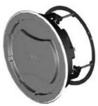
Close-up of a metallic square panel with a circular cutout and black cable, no visible text or symbols.- The grilles can be painted separately.
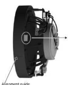
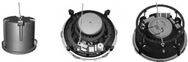
- To mount the speaker into the mounted speaker frame, align the connector on the speaker, with the corresponding connector on the speaker frame.
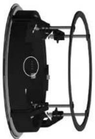
natural_image
Mechanical component with circular housing and mounting holes (no visible text or symbols)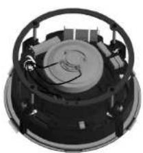
natural_image
Top-down view of a mechanical device with circular housing and internal components (no visible text or symbols)43 Quick Start
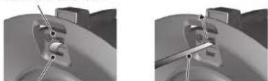
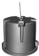
- To lock the speaker in place in the frame, press down on the three lock buttons on the front of the speaker. Note: After installation, if the square baffle does not press flat against the drywall, insert a 12 " screw in the oval depression in each corner of the baffle, and hand-tighten until the baffle is flat against the drywall.
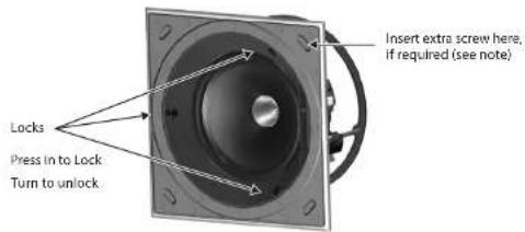
- To unlock the speaker from the speaker frame, first support the weight of the speaker, and rotate each lock with a screwdriver less than half a turn.
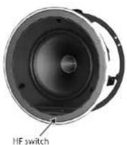
- The HF switch has three positions, with 0 dB being flat. Adjust as necessary to suit the room position and acoustic conditions.
EN
44 QQ 3/QCI BDC/PCI BDC
- Install the square grille by pressing it into the square baffle. Small magnets hold it in place. Alternatively, install the circular grille by pressing it into the circular baffle.
natural_image
Two views of a flat-panel speaker or fan device with black cables, shown from different angles (no text or symbols visible)QCI3 Terminals QCI 8DC Terminals PCI 8DC Terminals

natural_image
Three views of a mechanical device showing internal components and assembly (no text or symbols visible)45Quick Start
EN
ES
46 QQ 3/QC18DC/PCI8DC
Instalación
QCI3
natural_image
3D rendering of a square brake component showing external and side views (no text or symbols)47Quick Start
Release Tab Release Tab UP
48 QCI 3/QCI BDC/PCI BDC
natural_image
Three views of a mechanical component with labeled parts, showing front, side, and top views (no text or symbols beyond label)49 Quick Start
50 QCI3/QC 8DC/PCI8DC
INSTALACIÓN
QCI 8DC
Circular Battle Circular Battle and Speaker

natural_image
Two views of a flat panel with a central circular component, shown from different angles (no text or symbols visible)53Quick Start
natural_image
Three circular speaker components with mesh patterns, shown from front, side, and top views (no text or symbols)natural_image
Two identical circular mechanical components with internal curved cutouts, shown from different angles (no text or symbols)Painting Masks in Place
54 QCI3/QC 8DC/PCI8DC
INSTALACIÓN
PCI 8DC
natural_image
Mechanical assembly showing two circular components with mounting holes, one being cut (no text or symbols visible)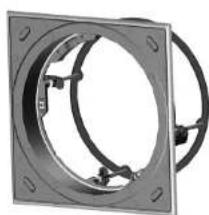
natural_image
Mechanical component with circular and rectangular features, no visible text or symbolsSpeaker Frame Square Baffle Speaker Frame with Square Baffle
natural_image
Mechanical assembly diagram showing two black circular components with mounting holes and a separate empty oval (no text or symbols)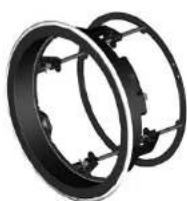
Speaker Frame Circular Baffle Speaker Frame with Circular Baffle
56 QCI3VQQ8DC/PCI8DC56
57Quick Start
natural_image
Exterior view of a circular mechanical component with mounting brackets (no text or symbols visible)
natural_image
Close-up of a square metallic panel with a circular cutout and black cable, no visible text or symbols.Painting Masks in Place
58 QCI3/QCI8DC/PCI8DC
natural_image
Two views of a speaker or audio device with visible sound waves and microphone components (no text or symbols)59 Quick Start
ES
60 QCI 3/QCI BOC/PCI BDC
QCI3 Terminals QCI 8DC Terminals PCI 8DC Terminals

natural_image
Three views of a mechanical device showing internal components and assembly (no text or symbols visible)61Quick Start
Installation
QCI3
natural_image
3D rendering of a square baffle component showing front and side views (no text or symbols)62 QCI VQCI BDC/PCI BDC
Release Tab Release Tab UP
natural_image
Two grayscale images showing mechanical components with alignment lines, no visible text or symbolsCable tie in tucked position Cable tie pulled out
natural_image
Three views of a speaker or fan device showing front, side, and top views with no visible text or symbols.FR
64 QQ 3/QC BDC/PCI BDC
65 Quick Start
INSTALLATION
QCI 8DC
66 QCI 3/QCI BDC/PCI BDC

Circular Battle Circular Battle and Speaker

natural_image
Close-up of a textured panel with a circular component and directional arrows indicating movement (no text or symbols)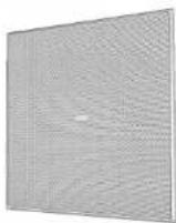
68 QCI 3/QCI BOC/PCI BDC
natural_image
Three circular objects with different surface textures, showing progressive changes from a textured to a black speaker-like structure (no text or symbols)natural_image
Two circular mechanical components with internal wavy patterns, shown from different angles (no text or symbols)Painting Masks in Place
69 Quick Start
INSTALLATION
PCI 8DC
- Run the speaker wire from your amplifier to this location, leaving enough slack to allow for the connection.
FR
70 QCI3/QCI8DC/PCI8DC
natural_image
Mechanical assembly diagram showing two circular components with mounting holes, one being rotated to form a square frame (no text or symbols present)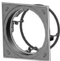
natural_image
Mechanical component with circular flange and mounting holes (no text or symbols visible)Speaker Frame Square Baffle Speaker Frame with Square Baffle
natural_image
Diagram showing two black circular components with internal brackets and a separate empty circular outline, no text or symbols present.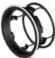
Speaker Frame Circular Baffle Speaker Frame with Circular Baffle
71Quick Start

natural_image
Mechanical assembly diagram showing a clamping mechanism with downward force arrows (no text or labels)72 QCI VQCI ADC/PCI BDC72
natural_image
Two views of a circular mechanical component with internal channels, labeled 'Painting Masks in Place' (no other text or symbols visible)FR
74 QCI 3/QCI BDC/PCI BDC
natural_image
Two views of a flat-panel speaker or fan device with black cables, shown from different angles (no text or symbols visible)75QuickStart
QCI3 Terminals QCI 8DC Terminals PCI 8DC Terminals
natural_image
Three views of a mechanical device showing internal components and assembly (no text or symbols visible)76 QJ 3/QC BDC/PQ 8DC
Installation
QCI3
natural_image
3D rendering of a square baffle component showing front, side, and top views (no text or symbols)77 Quick Start
Release Tab Release Tab UP
natural_image
Two mechanical assembly diagrams showing a cylindrical component with fasteners and a bracket, no text or symbols present.Cable tie in tucked position Cable tie pulled out
78 QCI3/QCI8DC/PCI8DC
natural_image
Three views of a mechanical component with labeled parts, showing front, side, and top views (no text or symbols beyond label)79 Quick Start
DE
80 QCI 3/QCI ROC/PCI 8DC
INSTALLATION
QCI 8DC
natural_image
Close-up of a black speaker or antenna with a pointer and circular head (no visible text or symbols)Clamp Screws (X4)
Square Baffle Square Baffle and Speaker
Circular Battle Circular Battle and Speaker
natural_image
Two views of a speaker grille showing internal components and sound waves (no text or symbols)83 Quick Start
natural_image
Three circular speaker components with different surface textures, shown from front, top, and side views (no text or symbols visible)natural_image
Two circular mechanical components with internal cross-sectional views, shown from different angles (no text or symbols visible)Painting Masks in Place
DE
84 QQ 3/QCI 8DC/PCI 8DC
INSTALLATION
PCI 8DC
natural_image
Mechanical assembly showing two circular components with mounting holes, one being rotated and the other tilted (no text or symbols visible)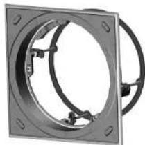
natural_image
Mechanical component with circular flange and mounting holes (no text or symbols visible)Speaker Frame Square Baffle Speaker Frame with Square Baffle
natural_image
Diagram showing two black circular components with internal brackets and a separate empty oval outline (no text or symbols)
Speaker Frame Circular Baffle Speaker Frame with Circular Baffle
86 QCI 3/QCI BOC/PCI 8DC86
natural_image
Close-up of a metallic square panel with a circular recess and black cable, no visible text or symbols.Painting Masks in Place
natural_image
Mechanical component diagram showing a circular component with internal structure and directional arrows (no text or symbols)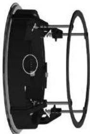
natural_image
Mechanical component with circular housing and mounting brackets (no visible text or symbols)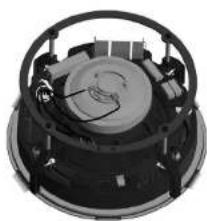
natural_image
Close-up of a mechanical device with internal components and mounting holes (no visible text or symbols)Alignment guide
87QuickStart
DE
88 QCI 3/QCI BOC/PCI BDC
natural_image
Two identical white circular speakers with black cables, shown from different angles (no text or symbols visible)DE
90 QCI 3/QCI BOC/PCI BDC
QCI3 Terminals QCI 8DC Terminals PCI 8DC Terminals

natural_image
Three views of a mechanical device showing internal components and assembly (no text or symbols visible)91QuickStart
Instalação
QCI3
natural_image
3D rendering of a mechanical component with two views showing internal structure (no text or symbols)92 QCI3/QCI8DC/PC8DC
Release Tab Release Tab UP
Cable-tie in tucked position Cable-tie pulled out
natural_image
Close-up of a mechanical component with a labeled 'Magnetic (X4)' and no visible text or symbols beyond the label.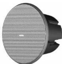
natural_image
Close-up of a black and white electronic device with a circular grille and base (no visible text or symbols)PT
94 QCI3/QCI8DC/PCI8DC
95 Quick Start
INSTALAÇÃO
QCI 8DC

Circular Battle Circular Battle and Speaker

natural_image
Close-up of a textured panel with circular cutouts and directional arrows indicating movement (no text or symbols)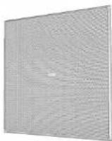
98 OC13/OC ADC/PC18DC
natural_image
Three circular speaker components with different surface textures, shown from front, top, and side views (no text or symbols)natural_image
Two circular mechanical components with internal curved features, shown from different angles (no text or symbols visible)Painting Masks in Place
99QuickStart
INSTALAÇÃO
PCI 8DC
100 QC 3/QC BDC/PC ADC
natural_image
Two views of a circular mechanical component with internal features, one shown from front and the other from side (no text or symbols visible)
natural_image
Mechanical component with circular flange and mounting holes (no text or symbols visible)natural_image
Mechanical assembly diagram showing two circular components with mounting holes and a separate wireframe outline (no text or symbols)
Speaker Frame Circular Baffle Speaker Frame with Circular Baffle
101QuickStart


natural_image
Mechanical assembly diagram showing a clamping tool with downward force arrows (no text or labels)102 QC 3/QC BDC/PC ADC102
natural_image
Two views of a circular mechanical component with attached wires, labeled 'Painting Masks in Place' (no other text or symbols visible)104 QC 3/QC BDC/PC ADC
natural_image
Two views of a flat-panel speaker or fan device with black cables, shown from different angles (no text or symbols visible)105Quick Start
QCI3 Terminals QCI 8DC Terminals PCI 8DC Terminals
natural_image
Interior view of a mechanical device with internal components and wiring (no visible text or symbols)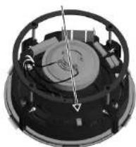
natural_image
Close-up of a mechanical component with a central rotating disk and internal components (no visible text or symbols)106 QC 3/QC BDC/PC ADC
Installazione
QCI3
natural_image
3D rendering of a square baffle component showing front, side, and top views (no text or symbols)107 Quick Start
Release Tab Release Tab UP
Cable-tie in tucked position Cable-tie pulled out
108 QC 3/QC BDC/PC ADC
natural_image
Three views of a speaker or fan device with labeled parts, showing front, side, and top views (no text or symbols on the device itself)109 Quick Start
110QCI3/QCI8DC/PCI8DC
INSTALLAZIONE
QCI 8DC
Circular Baffle Circular Baffle and Speaker

natural_image
Two views of a circular component with textured surfaces, showing internal structure and rotation direction (no text or symbols)113Quick Start
natural_image
Three circular speaker components with different surface textures, shown from top to side (no text or symbols)natural_image
Two identical circular mechanical components with internal curved cutouts, shown from different angles (no text or symbols)Painting Masks In Place
114QCI3/QCI8DC/PCI8DC
INSTALLAZIONE
PCI 8DC
Speaker Frame Square Baffle Speaker Frame with Square Baffle
natural_image
Mechanical assembly diagram showing two black circular components with mounting holes and a separate empty circular component (no text or symbols)
Speaker Frame Circular Baffle Speaker Frame with Circular Baffle
116QCI3/QCI8DC/PCI8DC116
117Quick Start
natural_image
Exterior view of a circular mechanical component with mounting brackets (no text or symbols visible)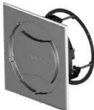
natural_image
Exterior view of a square electronic device with a circular cutout and black cable (no text or symbols visible)Painting Masks in Place
natural_image
Mechanical component with circular housing and mounting brackets (no visible text or symbols)
natural_image
Close-up of a mechanical component with circular housing and internal components (no visible text or symbols)118QCI3/QCI8DC/PCI8DC
natural_image
Two views of a speaker or audio device with visible sound waves and black cables (no text or symbols)120 0CI 3/QCI 8DC/PCI 8DC
QCI3 Terminals QCI 8DC Terminals PCI 8DC Terminals

natural_image
Three views of a mechanical device showing internal components and mounting holes (no text or symbols visible)121Click Start
Installatie
QCI3
natural_image
3D rendering of a square baffle component showing internal structure and mounting holes (no text or symbols)NL
122 QCI 3/QCI 8DC/PCI 8DC
Release Tab Release Tab UP

Cable-tie in tucked position Cable-tie pulled out
natural_image
Close-up of a mechanical component with a labeled 'Magnetic (X4)' and no visible text or symbols beyond the label.
natural_image
Close-up of a black and white electronic device with a circular speaker grille (no visible text or symbols)NL
124 QCI 3/QCI 8DC/PCI 8DC
125Quick Start
INSTALLATIE
QCI 8DC
126 QCI 3/QCI 8DC/PCI 8DC
Circular Battle Circular Battle and Speaker
natural_image
Two-panel image showing a speaker grille with a central lens, no text or symbols visibleNL
128 QCI 3/QCI 8DC/PCI 8DC
natural_image
Three circular speaker components with different surface textures, shown from top to bottom (no text or symbols visible)natural_image
Two circular mechanical components with internal curved cutouts, shown from different angles (no text or symbols visible)Painting Masks in Place
129Quick Start
INSTALLATIE
PCI 8DC
130 0CI 3/QCI 8DC/PCI 8DC
natural_image
Mechanical assembly showing two black circular components with mounting holes, one being rotated to a square plate (no text or symbols visible)
natural_image
Mechanical component with circular flange and mounting holes (no text or symbols visible)Speaker Frame Square Baffle Speaker Frame with Square Baffle
natural_image
Diagram showing two black circular components with internal brackets and a separate wireframe circle (no text or symbols)
Speaker Frame Circular Baffle Speaker Frame with Circular Baffle
131Click Start

natural_image
Mechanical assembly diagram showing a clamping tool with arrows indicating force or movement (no text or symbols present)NL
132 QCI 3/QCI 8DC/PCI 8DC 132
natural_image
Two views of a circular mechanical component with attached wires, labeled 'Painting Masks in Place' (no other text or symbols visible)natural_image
Technical diagram of a mechanical assembly showing three views: top view, front view, and side view (no text or symbols present)133 Quick Start
Insert extra screw here, if required (see note)
134 QCI 3/QCI 8DC/PCI 8DC
natural_image
Two views of a flat-panel speaker or fan device with black cables, shown from different angles (no text or symbols visible)135 Quick Start
QCI3 Terminals QCI 8DC Terminals PCI 8DC Terminals
natural_image
Three views of a mechanical device showing internal components and housing (no text or symbols visible)NL
SE
136 QCI 3/QCI 8DC/PCI 8DC
Installation
QCI3
natural_image
3D rendering of a square brake component showing external and internal views (no text or symbols)137 Quick Start
Release Tab Release Tab UP
Cable-tie in tucked position Cable-tie pulled out
natural_image
Three views of a speaker or fan device with labeled 'Magnets (X4)' and no other text or symbols visible.139Quick Start
140 QCI 3/QCI 8DC/PCI 8DC
INSTALLATION
QCI 8DC
Circular Baffle Circular Baffle and Speaker
natural_image
Two views of a flat-panel LED display showing internal components and grid pattern (no text or symbols)natural_image
Three circular speaker components with different surface textures, shown from front, side, and top views (no text or symbols visible)natural_image
Two identical circular mechanical components with internal curved cutouts, shown from different angles (no text or symbols visible)Painting Masks in Place
144 QCI 3/QCI 8DC/PCI 8DC
INSTALLATION
PCI 8DC
natural_image
Mechanical assembly showing two circular components with mounting holes, one being rotated into a square frame (no text or symbols visible)
natural_image
Mechanical component with circular flange and mounting holes (no text or symbols visible)natural_image
Diagram showing two black circular components with internal brackets and a separate empty oval outline (no text or symbols)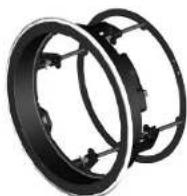
Speaker Frame Circular Baffle Speaker Frame with Circular Baffle
146 QCI 3/QCI 8DC/PCI 8DC 146
147 Quick Start
natural_image
Exterior view of a circular mechanical component with mounting brackets (no text or symbols visible)
natural_image
Exterior view of a square mechanical component with a circular cutout and black cable (no text or symbols visible)Painting Masks in Place
natural_image
Mechanical component diagram showing a circular component with labeled parts and wiring (no text or symbols present)Alignment guide
natural_image
Mechanical component with circular housing and mounting brackets (no visible text or symbols)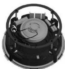
natural_image
Close-up of a mechanical component with circular housing and internal components (no visible text or symbols)1480CI3VQI8DC/PCI8DC
natural_image
Two views of a speaker or audio device with visible sound waves and microphone components (no text or symbols)SE
150 QCI3/QC 8OC/PCI8DC
QCI3 Terminals QCI 8DC Terminals PCI 8DC Terminals
natural_image
Three views of a mechanical device showing internal components and assembly (no text or symbols visible)151Quick Start
Instalacja
QCI3
natural_image
Three views of a mechanical component with a square baffle, shown from different angles (no text or symbols present)152 QCI3/QC 800/PCI8DC
Release Tab Release Tab UP

Cable-tie in tucked position Cable-tie pulled out
natural_image
Close-up of a mechanical component with a circular head and central hub, labeled 'Vance (V6)' (no other text or symbols visible)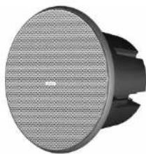
natural_image
Close-up of a black and white electronic device with a circular grille and central hub (no visible text or symbols)154 QCI3/QC 80C/PCI8DC
155Quick Start
INSTALACJA
QCI 8DC
Square Baffle Square Baffle and Speaker

Circular Battle Circular Battle and Speaker

natural_image
Two-panel diagram showing a circular component being cut off into a grid-patterned panel (no text or symbols)158 QCI 3/QC 80C/PCI8DC
natural_image
Three circular speaker components with different surface textures, shown from front, top, and side views (no text or symbols)natural_image
Two circular mechanical components with internal curved features, shown from different angles (no text or symbols visible)Painting Masks in Place
INSTALACJA
PCI 8DC
160 QCI 3/QCI BDC/PCI BDC
natural_image
Mechanical assembly showing two black circular components with mounting holes and a separate view of a rectangular frame (no text or symbols visible)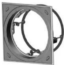
natural_image
Mechanical component with circular flange and mounting holes (no text or symbols visible)Speaker Frame Square Baffle Speaker Frame with Square Baffle
natural_image
Mechanical assembly diagram showing two circular components with mounting holes and a separate wireframe outline (no text or symbols)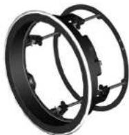
Speaker Frame Circular Baffle Speaker Frame with Circular Baffle
161 Quick Start

natural_image
Mechanical valve assembly diagram showing internal components and force direction arrows (no text or labels)PL
162 QCI 3/QCI BDC/PCI BDC 162
natural_image
Exterior view of a circular mechanical component with internal channels and mounting brackets (no text or symbols visible)Painting Masks in Place
natural_image
Exterior view of a square electronic device with a circular vent and black cable (no text or symbols visible)natural_image
Pure mechanical component diagram without any text, numbers, or symbols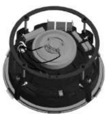
natural_image
Close-up of a mechanical component with internal gears and mounting holes (no visible text or symbols)163Quick Start
164 QCI 3/QCI BDC/PCI BDC
natural_image
Two views of a flat-panel speaker or audio device with black cables, no visible text or symbols.165Quick Start
166 QCI 3/QCI BDC/PCI BDC
167Quick Start
QCI 3 Dimensions QCI 8DC Dimensions
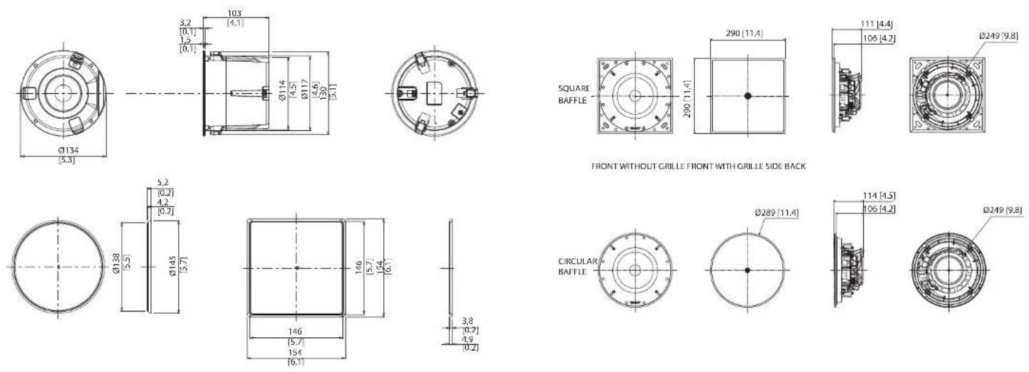
Dimensions are mm [inch] Dimensions are mm [inch]
168 QCI 3/QCI BDC/PCI BDC
PCI 8DC Dimensions
![SQUARE BAFFLE 290 [11.4] 290 [11.4] 141 [5.5] 135 [5.3] Ø249 [9.8]](/content/2026/04/694296/images/c2cace753bbdca9ac8509b1862b46b2a40bfc3884164b48161e90464ce5bdc81.jpg)
FRONT WITHOUT GRILLE FRONT WITH GRILLE SIDE BACK
![CIRCULAR BAFFLE Ø289 [11.4] 143 [5.6] 135 [5.3] Ø249 [9.8]](/content/2026/04/694296/images/a0c836b4b0c50e67eca55a716c2e8258691754b3319eaf3d803794ba8f4f0c20.jpg)
Dimensions are mm [inch]
169 Quick Start
EN

Specifications
QCI 3 QCI 8DC PCI 8DC
| Performance | |||
| Frequency response (±3 dB) | 110 Hz - 20 kHz | 35 Hz - 20 kHz | 50 Hz - 20 kHz |
| Frequency response (-10 dB) | 80 Hz - 20 kHz | 25 Hz - 20 kHz | 30 Hz - 20 kHz |
| Sensitivity (1 W @ 1 m) | 84 dB | 87 dB | |
| Directivity factor (Q) | 6.4 averaged 1 kHz to 10 kHz | 6.8 averaged 1 kHz to 10 kHz | 6.6 averaged 1 kHz to 10 kHz |
| Directivity index (DI) | 8 averaged 1 kHz to 10 kHz | 8.3 averaged 1 kHz to 10 kHz | 8.2 averaged 1 kHz to 10 kHz |
| Power handling (IEC) | |||
| Average | 40 W | 80 W | |
| Programme | 80 W | 160 W | |
| Peak | 160 W | 320 W | |
| Recommended amplifier power | 120 W @ 8 Ω | 240 W @ 8 Ω | |
| Nominal Impedance (Lo Z) | 8 Ω | ||
| Rated maximum SPL(1 m, Lo Z) | 103 dB | 109 dB | |
| Average | 100 dB | 106 dB | |
| Peak | 106 dB | 112 dB | |
| Crossover point | NA | 1.6 kHz | |
| Coverage angles | |||
| 500 Hz | 180° horizontal, 180° vertical | 180° horizontal, 145° vertical | |
| 1 kHz | 180° horizontal, 180° vertical | 117° horizontal, 117° vertical | 117° horizontal, 135° vertical |
| 2 kHz | 135° horizontal, 135° vertical | 108° horizontal, 108° vertical | 85° horizontal, 99° vertical |
| 4 kHz | 66° horizontal, 66° vertical | 121° horizontal, 121° vertical | 124° horizontal, 141° vertical |
QCI 3 QCI 8DC PCI 8DC
| Transducers | |||
| Low frequency diameter/ material/type | 85 mm (3") 219 mm (8") | 210 mm (8") | |
| High frequency diameter/ material/type | — 25.4 mm (1") | ||
| Physical | |||
| Back can — | Option 1 (BACK CAN S): Steel, with powder coating Option 2 (BACK CAN C1): High density expandable polystyrene (EPS) | Option 1 (BACK CAN S): Steel, with powder coating Option 2 (BACK CAN C2): High density expandable polystyrene (EPS) | |
| Baffle Reflex loaded UL96 V-0 rated ABS | |||
| Grille Steel, with weather resistant coating | |||
| Clamping design Security toggle clamp | |||
| Connectors Phoenix Contact terminal block | |||
| Dimensions (HxWxD) | 154 x 154 x 105 mm(6.1 x 6.1 x 4.1") | 290 x 290 x 114 mm(11.4 x 11.4 x 4.5") | 290 x 290 x 143 mm(11.4 x 11.4 x 5.6") |
| Bezel dimensions | Circular: φ145 mm (5.7")Square: 154 x 154 mm (6.1 x 6.1") | Circular: φ289 mm (11.4")Square: 290 x 290 mm (11.4 x 11.4") | |
| Mounting depth 100 mm (4.0") 106 mm (4.2") 135 mm (5.3") | |||
| Hole cutout dimensions φ117 mm (4.6") | φ250 mm (9.8") | ||
| Net weight | 0.9 kg (1.98 lbs) | 3.1 kg (6.8 lbs) | 3.9 kg (8.6 lbs) |
| Packed quantity | 2 | 1 | |
| Included accessories | Square grille, square baffle,circular grille, screw | Square grille, square baffle, circular grille, circular baffle,circular paint mask, square paint mask, cutout template, screw | |
| Optional accessories | PMX 3 | Option 1: BACK CAN SOption 2: BACK CAN C1Option 3: PMX 8 | Option 1: BACK CAN SOption 2: BACK CAN C2Option 3: PMX 8 |

172 QCI 3/QCI 8DC/PCI 8DC
Other important information

Important Information A

es rantes
-
Register online. Please register your new Music Tribe equipment right after you purchase it by visiting musictribe.com. Registering your purchase using our simple online form helps us to process your repair claims more quickly and efficiently. Also, read the terms and conditions of our warranty, if applicable.
-
Malfunction. Should your Music Tribe Authorized Roseller not be located in your vicinity, you may contact the Music Tribe Authorized Fupiller for your country listed under "Support" at musictribe.com. Should your country not be listed, please check if your problem can be dealt with by our "Online Support" which may also be found under "Support" at musictribe.com. Alternatively, please submit an online warranty claim at musictribe.com BEFORE returning the product.
1. Registro online.
Other important information

Hereby, Music Tribe declares that this product is in compliance with Directive 2011/65/EU and Amendment 2015/863/EU, Directive 2012/19/EU, Regulation 519/2012 REACH SVHC and Directive 1907/2006/EC, and this passive product is not applicable to EMC Directive 2014/30/EU, LV Directive 2014/35/EU.
Full text of EU DoC is available at https://community.musictribe.com/
EU Representative: Music Tribe Brands DK A/S
Address: Gammel Strand 44, DK-1202 København K, Denmark
UK Representative: Music Tribe Brands UK Ltd.
Address: 6 Lloyds Avenue, Unit 4CL London EC3N 3AX, United Kingdom
175Quick Start

TANNOY