
CVS 4 MICRO - Loudspeaker TANNOY - Free user manual and instructions
Find the device manual for free CVS 4 MICRO TANNOY in PDF.


| Product Type | In-ceiling loudspeaker |
| Brand | Tannoy |
| Model | CVS 4 MICRO |
| Driver Size | 4 inches |
| Frequency Response | 80 Hz - 20 kHz |
| Sensitivity | 86 dB (1W/1m) |
| Impedance | 8 ohms |
| Power Handling (RMS) | 30 W |
| Power Handling (Peak) | 60 W |
| Dimensions (Diameter x Depth) | 140 mm x 80 mm |
| Cut-out Diameter | 120 mm |
| Weight | 0.8 kg |
| Material | ABS plastic with metal grille |
| Color | White |
| Mounting | Ceiling mount with spring clips |
| Connector Type | Spring-loaded terminals |
| Grille | Perforated metal, paintable |
| Warranty | 5 years |
| Recommended Use | Background music, paging |
| Maintenance | Dust with a dry cloth; do not use solvents |
| Safety | Ensure proper electrical isolation; professional installation recommended |
| Spare Parts | Grille and driver assembly available |
Frequently Asked Questions - CVS 4 MICRO TANNOY
User questions about CVS 4 MICRO TANNOY
0 question about this device. Answer the ones you know or ask your own.
Ask a new question about this device
Download the instructions for your Loudspeaker in PDF format for free! Find your manual CVS 4 MICRO - TANNOY and take your electronic device back in hand. On this page are published all the documents necessary for the use of your device. CVS 4 MICRO by TANNOY.
USER MANUAL CVS 4 MICRO TANNOY
Tanncy has a policy of continuous improvement and this specification sheet provides the latest information at the time of printing. All specifications may be subject to further change. Please contact the Tannoy website for the latest information.
CVS
Tannoy (Direct 90) 00 449 (0) 1236 4201999E: enquiries@tannoy.com TCGI (ROW sales) T: 00 45 8742 7000 9 9E: info@tcgroup-international.com TCGA (Americas sales) 9T: 00 1 (b19) 745 11699E: info@tcgroup-americas.com Tannoy Middle East 9T: 00 971 (04) 4401208 9E: enquiries@tannoy.com
Tamroy adopts a policy of continuous improvement and product specification is subject to change
tannoy.com

REVISION DATE: 03 March 201
6101 0457
CVS 4 TEMPLATE CUTOUT SIZE: 180mm
CVS 6 TEMPLATE CUTOUT SIZE: 250mm
CVS 8 TEMPLATE CUTOUT SIZE: 320mm
TSNETNOC
1 | INTRODUCTION
2 | UNPACKING
3 | SAFETY NOTICES
4 PRODUCT FEATURE IDENTIFICATION
5 | ACCESSORIES
6 | INSTALLATION GUIDE
6.1 MECHANICAL INSTALLATION GUIDE FOR SUSPENDED CEILINGS
6.2 MECHANICAL INSTALLATION GUIDE FOR SHEET-ROCK CEILINGS
6.3 MECHANICAL INSTALLATION INSTRUCTIONS FOR OPTIONAL PLASTER RING
7 WIRING AND SETTING UP
8 | DIMENSIONS
8.1 CVS 4 DIMENSIONS
8.2 CVS 6 DIMENSIONS
CVS 8 DIMENSIONS8.3
9 | TECHNICAL SPECIFICATIONS
PAINTING10
11 | WARRANTY
12 | DECLARATION OF CONFORMITY
1. INTRODUCTION
Thank you for purchasing this Tannoy Ceiling loudspeaker. This product range is suited for high-level music and speech reinforcement applications requiring exceptional sonic quality with uncompromised reliability.
2: UNPACKING
Every Tannoy product and accessory is carefully inspected before packing. After unpacking, please inspect your product to make sure no damage has occurred in transit. In the unlikely event of any damage, would you please notify your dealer immediately and retain your shipping carton, as your dealer may ask you to return the faulty unit to them for inspection.
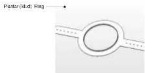
Each CVS loudspeaker is packed in pairs and provided with the following accessories as standard: C Ring, tile-bridge kit, grille, cut-out template, and paint mask. A plaster (mud) ring is also available as an optional extra.
3. SAFETY NOTICES
Some regional construction codes require the use of a secondary method of securing loudspeakers in ceiling to provide security of a backup support. A secondary support line should be attached from the safety loop on the rear of the product to a source point on the ceiling. Please consult the relevant construction codes in your region.
When using a power driver to install the product it is essential to use the correct torque level settings to avoid over tightening and damage to the calling material or clamps
Recommended torque setting: 1.5Nm
Tannoy will not be held responsible for any damages caused by the improper installation of these loudspeakers.
Electrical Safety Notice: to comply with the standard UL1480, metal-clad flexible conduit (BX) is required for connection to the terminal block for proper earth grounding.
SAFETY NOTE:
In order to comply with the relevant fire safety regulations (i.e. BS 5639.1998), it is required that in the event of fire, that failure of the circuit to which the loudspeaker is connected does not occur before evacuation of the building is complete. Suitable measures include:
a) use of terminal blocks (for connection to primary) with a melting point of not less than 650°C, for example constructed from ceramic materials;
b) use of terminal blocks of a lower melting point but protected with thermal insulation; c) use of terminal blocks such that, on melting, an open-circuit or a short-circuit does not occur.
- PRODUCT FEATURE IDENTIFICATION: 5. ACCESSORIES:
CVS 4
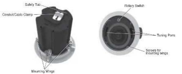
CVS 6
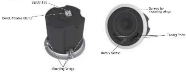
CVS 8
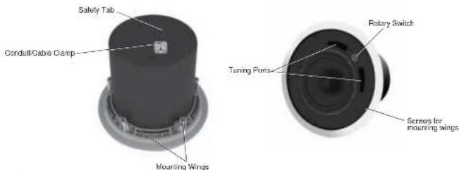
Standard Accessories
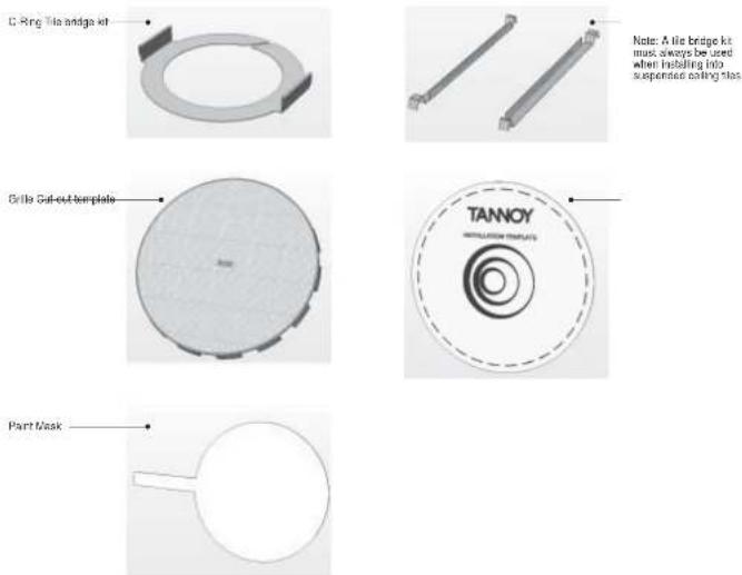
Optional Accessories
6.1 MECHANICAL INSTALLATION GUIDE FOR SUSPENDED CEILINGS
1 Remove the ceiling tile from its frame and place it on a flat surface. Mark the put-out area on the ceiling tile by tracing around the template provided.
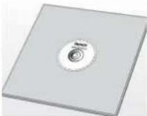
2 Cut out the hole in the ceiling tie using a circular saw or pad saw.
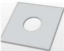
3 Place the C-ring and tie bridge on top of the ceiling panel aligning the C-ring over the hole, and screw the C-ring to the tie bridge using the fixings provided.

4 Side the speaker assembly through the hole and turn the screws on the front of the speaker to extend the mounting wings. Tighten the screws until a firm grip is achieved. It using a power driver, Tanney recommends a torque setting of 1.5Nm
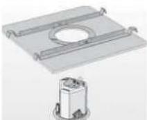
DO NOT OVERTIGHTEN!
5 Side the tile panel back into the suspended ceiling. The tile bridge ends will catch over the ceilings, supporting the weight of the speaker.
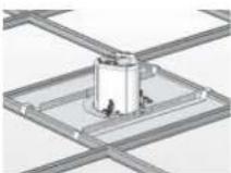
6 Connect a Secondary Support Line to safety lab. Some construction codes require use of this secondary support point, which should connect to a separate secure support point using a suitable support line. Consult construction codes in your region
Go to section 7 for instructions on wiring and set-up instructions.
6.2 MECHANICAL INSTALLATION GUIDE FOR SHEET ROCK (PLASTER BOARD) CEILINGS
1 Mark the put-out area on the ceiling by tracing around the template provided.
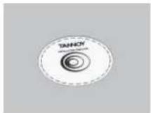
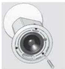
2 Cut cut the hole in the ceiling using a circular saw or pod saw, then slide the C-ring into the ceiling, signing it over the cut-cut hole.

3 Go to section 7 for wiring and set-up instructions then return to point 4 below.
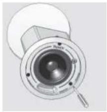
4 Side the speaker assembly through the hoic and turn the screws to extend the mounting wings. Tighten the screws until a firm grip is achieved.
If using a power driver, Tanney recommends a torque setting of 1.5Nm.
DO NOT OVERTIGHTEN!
5 Connect a Secondary Support Line to safety lab. Some construction codes require use of the secondary support point, which should connect to a separate secure support point using a suitable support line. Consult construction codes in your region
6 Insert grille by pushing it onto the speaker.
natural_image
Technical illustration of a mechanical component with concentric rings and a central hub (no text or symbols)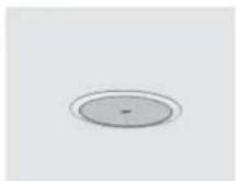
6.3 MECHANICAL INSTALLATION INSTRUCTIONS FOR OPTIONAL PLASTER RING:
An optional plaster (mud) ring bracket is available from Tanney. This bracket is designed to be pre installed into newly constructed, non-suspended ceilings.
1 Nell or screw the pieferring to the joints.
2 Lay the speaker wiring to where the speaker will be filled and complete the plastering work on the ceiling.
3 Cut out the hole in the ceiling using a circular saw or pad saw.
4 Go to section 7 for instructions on writing their return to paint 5 below.
5 Side the speaker assembly through the hole and turn the screws to extend the mounting wings Tighten the screws until a firm grip is achieved.
If using a power driver, Torney recommends a torque setting of 1.6Nm.
DO NOT OVERTIGHTEN!
6 Connect a Secondary Support Line to safety lab. Some construction codes require use of the secondary support point, which should connect to a separate secure support point using a suitable support line. Consult construction codes in your region.
7 Insert gripe by pushing it onto the speaker.


natural_image
Mechanical component diagram showing a circular housing with a central lens and mounting holes (no text or symbols)
7. WIRING AND SETTING UP:
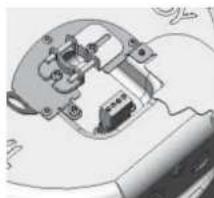
1 Open the wiring cover at the back of the speaker can to access the Euro type connector plug and socket.
2 For connection to an amplifier, use sine 1 and 2.
• Pin 1 is positive
• Pin 2 is negative
For connection to additional speakers in a distributed line,
pins 3 and 4 are in parallel where:
• Pin 3 is negative
- Pin 4 is positive
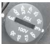
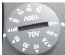
3 Close the wiring cover and tighten both screws on the cable clamp. Use the rotary switch located on the front of the unit to select whether you wish to use the speaker in a low-impedance or distributed-line application
THE SPEAKER IS SUPPLIED IN LOW IMPEDANCE MODE. NEVER CONNECT THE SPEAKER TO A 70/100 VOLT AMPLIFIER WHILE IT IS SET FOR LOW IMPEDANCE.
4 The CVS 4 is titled with a 30W transformer. When used in distributed-line systems, the transformer can be tapped at 30W, 15W and 7.5W, with an additional 3.75W tapping for 70.7V line systems.
5 The CVS 6 is tilted with a 60W transformer. When used in distributed line systems, the transformer can be tapped at 60W, 30W, and 15W, with an additional 7.5W tapping for 70.7V line systems.
6 | The CVS 6 is filled with a 60W transformer. When used in distributed-line systems, the transformer can be tapped at 60W, 30W, and 15W, with an additional 7.5W lapping for 70.7V line systems.
natural_image
Mechanical assembly diagram showing internal components and wiring (no text or labels)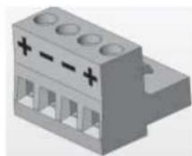
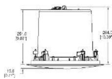
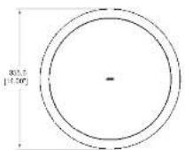
8.1 CVS 4 DIMENSIONS:
CVS 4 TEMPLATE CUTOUT SIZE: 180mm

8.2 CVS 6 DIMENSIONS:
CVS 6 TEMPLATE CUTOUT SIZE: 250mm

8.3 CVS 8 DIMENSIONS:
CVS 8 TEMPLATE CUTOUT SIZE: 320mm

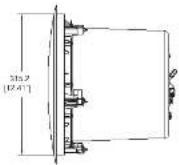

CVS4
TANNOY
TECHNICAL SPECIFICATIONS
| System | CVS4 |
| Frequency Response (-3dB) ^15 | 10 Hz - 19 kHz |
| Frequency Range (-10dB) ^15 | 77Hz - 220Hz |
| System Sensitivity (1W @1m) ^15 | 97.5d (1W = 2.45V for 6 Ohms) |
| Nominal Coverage Angle | 30 degrees nominal |
| Coverage Angle (1kHz to 5kHz) | 100 degrees |
| Directivity Factor (Q) | 5.5 averaged 1kHz to 8kHz |
| Directivity Index (Df) | 7.1 averaged 1kHz to 8kHz |
| Rated Maximum SPL | 100dB (average)100dB (peak) |
| Power Handling ^16 | |
| Average | 40W |
| Programme | 80W |
| Peak | 190W |
| Recommended Amplifier Power | 80W @ 8 Ohms |
| Nominal Impedance | 6 Ohms |
| Transformer Tape | |
| (Vin front rotary switch) | 30W / 15W / 7.2W / 3.75W / QI |
| 70V | & low impedance operation |
| 100V | 30W / 15W / 7.2W / OFF& low impedance operation |
| Distortion | |
| 1% Full Power | 2nd Harmonic Srd Harmonic |
| 250Hz | 0.23%-0.112% |
| 1kHz | 0.225% 0.230% |
| 10kHz | 0.163% 0.325% |
| 10% Full Power | 2nd Harmonic Srd Harmonic |
| 250Hz | 0.95%-0.169% |
| 1kHz | 0.316% 0.323% |
| 10kHz | 0.444% 0.327% |
| Crossover Point | 2.7kHz |
| Transducers | |
| Low Frequency | 10mm (5.00") Mineral Loaded |
| High Frequency | 10mm (0.75") |
| Physical | |
| Enclosure | |
| Back can | Zinc plated steel |
| Brill | Hotex loaded UL 94V Optoe ABS |
| Gritte | Sorel with weather resistant casing |
| Safety Features | Safety ring loaded at rear of enclosure for load heating safety board |
| Clamping Design | Security foggy camp |
| Back Can Options | |
| Cable Entry Options | Cave clamp & squeeze connector for dental up to 22mm |
| Connectors | Removable locking connector with screw ferrimms with loop through* facility |
| Safety Agency Ratings | UL 1490, UL 2943, CE |
| Hole Cutout Diameter | 190mm |
| DimensionsRabel diameter | 215.6mm (8.36") |
| Front of ceiling to rear of back arm | 202.5mm (7.97") |
| Front of ceiling to top of safety loo | 214.5mm (8.46") |
| Net Weight (wt) | 2.50kg |
| Included Accessories | C Ring, the bridge part mask actual lamnalla, g/m |
| Optional Accessories | Plaster (mudi ring) |

CVS6
TANNOY.
TECHNICAL SPECIFICATIONS
| System | CVS6 |
| Frequency Response (-3dB)(1) | 78Hz - 21kHz |
| Frequency Range (-10dB)(2) | 60Hz - 24kHz |
| System Sensitivity (1W @ms)(3) | 51dB (1W = 2.40V for 6 Ohms) |
| Nominal Coverage Angle | 50 degrees carried |
| Coverage Angle (1kHz to 6kHz) | 93 degrees |
| Directivity Factor (D) | 7.7 averaged 1kHz to 6kHz |
| Directivity Index (D) | 8 averaged 1kHz to 6kHz |
| Rated Maximum SPL | 108dB (coverage) 115dB (pcc/s) |
| Power Handling(3) Average | 60W |
| Programme | 120W |
| PcsA | 240W |
| Recommended Amplifier Power | 120W @ 6 Ohms |
| Nominal Impedance | 6 Ohms |
| Translomer Tape [High rotary switch] 70V | 60W / 30W / 15W / 7.2W / 0Hz & low impedance operation |
| 10CV | 60W / 30W / 15W / OFF & low impedance operation |
| Distortion 1% Full Power | 2nd Harmonic 3rd Harmonic 0.439% 0.140% 0.390% 0.459% 0.233% 0.023% |
| 250Hz | 2nd Harmonic 3rd Harmonic 1.159% 0.214% 1.014% 0.845% 0.047% |
| 1kHz | 1kHz 0.214% 0.085% 0.845% 0.047% |
| 10kHz | |
| 10% Full Power | 2nd Harmonic 3rd Harmonic 1.159% 0.214% 1.014% 0.845% 0.047% |
| 250Hz | |
| 1kHz | |
| 10kHz | |
| Crossover Point | 2.5kHz |
CVS8
TANNOY.
TECHNICAL SPECIFICATIONS
| System | CVS8 | |
| Frequency Response (-3dB)1) | 79 Hz - 21kHz | |
| Frequency Range (-30dB)1) | 60Hz - 24kHz | |
| System Sensitivity (1W @1m)1) | 93dB (1W = 2.45V for 6 Ohms) | |
| Nominal Coverage Angle | 90 degrees nominal | |
| Coverage Angle (1kHz to 6kHz) | 84 degrees nominal | |
| Directivity Factor (Q) | 14.7 averaged 1kHz to 9kHz | |
| Directivity Index (QI) | 11.7 averaged 1kHz to 6kHz | |
| Rated Maximum SPL | 110dB (average)117dB (pack) | |
| Power Handling1) | ||
| Average | 60W | |
| Programme | 120W | |
| Peak | 240W | |
| Recommended Amplifier Power | 120W @ 6 Ohms | |
| Nominal impedance | 6 Ohms | |
| Transformer Tape | ||
| (vit front rotary section) | ||
| 70V | 80W / 30W / 10W / 7.5W / OFF& low impedance operation | |
| 100V | 60W / 30W / 12W / OFF& low impedance operation | |
| Distortion | ||
| 1% Full Power | 2nd Harmonic | 3rd Harmonic |
| 250Hz | 0.35% / 0.25% | |
| 1kHz | 0.12% / 0.03% | |
| 100Hz | 0.12% / 0.03% | |
| 10% Full Power | 2nd Harmonic | 3rd Harmonic |
| 250Hz | 1.10% / 0.25% | |
| 1kHz | 0.35% | 0.70% |
| 100Hz | 0.32% / 0.03% | |
| Crossover Point | 6Hz | |
| Transducers | |
| Low Frequency | Covered 200 mm (8.00") mineral loaded cone material |
| High Frequency | 14mm (pl.75") |
| Physical | |
| Enclosure Back can | Birch Mount (BM)21x skibbed steelHotex based UL 94V 9 graced ABSSteel with weather 'residential casing |
| Units Circle | |
| Safety Features | Safety ring located at rear of enclosure for load bearing safety bond |
| Clamping Design | Security xoggle clamp |
| Back Can | |
| Cable Entry Options | Cable clamp & squeeze connector for pondal up to 22mm |
| Connectors | Removable locking connector with similar terminals with loop through 'facility |
| Safety Agency Ratings (pending) UL 1480, UL 2943, CL | |
| Hole Cutout Diameter | 320mm (12.6") |
| Dimensions Basel diameter | 350.6mm (14.60") |
| Front of ceiling to rear of lock cap | 251.6mm (9.80") |
| Front of ceiling to top of safety logo | 254.6mm (10.89") |
| Tempate hole cutout size | 250mm (9.84") |
| Net Weight (ea) | 5.3kg (11.68kg) |
| Included Accessories | O Ring, 16 bridge, part mask outlay template, grate |
| Optional Accessories | Plaster (primely ring) |
10. PAINTING
If desired, the grille and baffle panel may be painted to match the surrounding décor.
Painting the baffle:
- Carefully mask off the driver assembly using the paint mask provides to ensure that the paint does not come into contact with the cone and roll surround.
© Apply several thin coats of paint – this will provide a better finish than one overly thick coat.
Painting the grille:
- Carefully remove the acoustically transparent foam from the reverse side of the grille. - Paint the grille and then replace the foam - several thin coats of paint will provide a better finish than one
- Re-bond the loam to the grille over the entire area using a light spray-adhesive to avoid audible resonances.
11. WARRANTY
No maintenance of the CVS loudspeaker is necessary.
All Tannoy professional loudspeaker products are covered by a 5 year warranty from the date of manufacture subject to the absence of misuse, overload or accidental damage. Claims will not be considered if the serial number has been altered or removed. Work under warranty should only be carried out by a Tannoy Professional dealer or service agent. This warranty in no way affects your statutory rights. For further information please contact your dealer or distributor in your country. If you cannot locate your distributor please contact Customer Services, Tannoy Ltd at the address given below.
Customer Services
Tannoy Ltd.
Rosehall Industrial Estate
Coatoridge
Strathclyde
ML54TF
Scotland
Tel: 01236 420199 (National)
+44 1236 420199 (International)
Fax: 01236 428230 (National)
+44 1236 428230 (International)
E-mail: enquiries@tannoy.com
DO NOT SHIP ANY PRODUCT TO TANNOY WITHOUT PREVIOUS AUTHORISATION
Our policy commits us to incorporating improvements to our products through continuous research and development. Please confirm current specifications for critical applications with your supplier.
12. DECLARATION OF CONFORMITY:

The following apparatus is/are manufactured in China for Tannoy Ltd of Rosehall Industrial estate, Coatbridge, Scotland, ML5 4TF and conform(s) to the protection requirements of the European Electromagnetic Compatibility Standards and Directives relevant to Domestic Electrical Equipment. The apparatus is designed and constructed such that electromagnetic disturbances generated do not exceed levels allowing radio and telecommunications equipment and other apparatus to operate as intended, and, the apparatus has an adequate level of intrinsic immunity to electromagnetic disturbance to enable operation as specified and intended. This equipment conforms to the requirements of the EMC Directive 89/33/EEC, amended by 92/31/EEC and the requirements of the Low Voltage Directive 73/23/EEC, amended by 93/68/EEC.
Details of the Apparatus: Tannoy Contractor Loudspeaker
Model Numbers: CVS 4
CVS 6
CVS 8
Applicable Standards: EN55103-1 1996 Emission
EN55103-2 1996 Immunity
Electrical Safety EN 60065: 1993
Signed:
Position: Director of Engineering
Tannoy Professional
Date: 23/11/2011
For Tannoy Ltd
NOTESNOTES


- CVS
- TSNETNOC
- INTRODUCTION
- 2: UNPACKING
- SAFETY NOTICES
- SAFETY NOTE:
- MECHANICAL INSTALLATION GUIDE FOR SUSPENDED CEILINGS
- MECHANICAL INSTALLATION GUIDE FOR SHEET ROCK (PLASTER BOARD) CEILINGS
- MECHANICAL INSTALLATION INSTRUCTIONS FOR OPTIONAL PLASTER RING:
- WIRING AND SETTING UP:
- CVS4
- TANNOY
- CVS6
- TANNOY.
- CVS8
- PAINTING
- WARRANTY
- DECLARATION OF CONFORMITY:
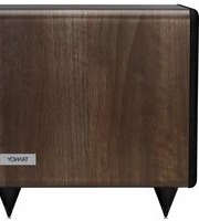
Brand : TANNOY
Model : CVS 4 MICRO
Category : Loudspeaker