
SAT 3 - Speaker TANNOY - Free user manual and instructions
Find the device manual for free SAT 3 TANNOY in PDF.

| Product Type | Passive Satellite Speaker |
| Brand | Tannoy |
| Model | SAT 3 |
| Usage | Background and foreground music in bars, restaurants and shops |
| Speaker Type | 2.5" (6.35 cm) lightweight full-range |
| Average Power | 15 Watts |
| Program Power | 25 Watts |
| Frequency Response | 200 Hz - 20 kHz (-10 dB) |
| Dispersion | Wide constant directivity |
| Finish | Semi-matte black or white |
| Mounting | Wall and ceiling mount with pan/tilt included |
| Connection | 2-conductor Euroblock connector |
| Installation | Must be connected to a SAT SUB subwoofer or compatible amplifier |
| Maintenance and cleaning | Clean with a dry cloth. Do not use liquids. |
| Safety | Do not open the device. Use only professional cables. Follow safety instructions. |
| Spare parts and repairability | No user-serviceable parts. Contact a qualified professional for any repairs. |
| Warranty | Limited warranty. Visit community.musictribe.com for details. |
| Operating Temperature | Up to 45°C (tropical or moderate climate) |
| Included Accessories | Mounting bracket, Euroblock connectors, screws |
Frequently Asked Questions - SAT 3 TANNOY
User questions about SAT 3 TANNOY
0 question about this device. Answer the ones you know or ask your own.
Ask a new question about this device
Download the instructions for your Speaker in PDF format for free! Find your manual SAT 3 - TANNOY and take your electronic device back in hand. On this page are published all the documents necessary for the use of your device. SAT 3 by TANNOY.
USER MANUAL SAT 3 TANNOY
natural_image
Line drawing of a double door with four identical TV speakers standing beside it, no text or symbols present.SAT 3
Surface Mount Satellite Loudspeaker for Commercial Applications
SAT SUB
Compact Wall Mount Subwoofer for Commercial Applications
SAT SUB 4 PACK
Packaged Satellite-Subwoofer Loudspeaker System for Commercial Applications
23 Quick Start Guide SAT SUB and SAT 3
EN
EN Important Safety Instructions
ES
Terminals marked with this symbol carry electrical current of sufficient magnitude to constitute risk of electric shock. Use only high-quality professional speaker cables with 1/4" TS or twist-locking plugs pre-installed. All other installation or modification should be performed only by qualified personnel.
This symbol, wherever it appears, alerts you to the presence of uninsulated dangerous voltage inside the enclosure - voltage that may be sufficient to constitute a risk of shock.
This symbol, wherever it appears, alerts you to important operating and maintenance instructions in the accompanying literature. Please read the manual.
Caution To reduce the risk of electric shock, do not remove the top cover (or the rear section). No user serviceable parts inside. Refer servicing to qualified personnel.
Caution To reduce the risk of fire or electric shock, do not expose this appliance to rain and moisture. The apparatus shall not be exposed to dripping or splashing liquids and no objects filled with liquids, such as vases, shall be placed on the apparatus.
Caution These service instructions are for use by qualified service personnel only. To reduce the risk of electric shock do not perform any servicing other than that contained in the operation instructions. Repairs have to be performed by qualified service personnel.
- Read these instructions.
- Keep these instructions.
- Heed all warnings.
- Follow all instructions.
-
Do not use this apparatus near water.
-
Clean only with dry cloth.
-
Do not block any ventilation openings. Install in accordance with the manufacturer's instructions.
-
Do not install near any heat sources such as radiators, heat registers, stoves, or other apparatus (including amplifiers) that produce heat.
-
Do not defeat the safety purpose of the polarized or grounding-type plug. A polarized plug has two blades with one wider than the other. A grounding-type plug has two blades and a third grounding prong. The wide blade or the third prong are provided for your safety. If the provided plug does not fit into your outlet, consult an electrician for replacement of the obsolete outlet.
-
Protect the power cord from being walked on or pinched particularly at plugs, convenience receptacles, and the point where they exit from the apparatus.
-
Use only attachments/accessories specified by the manufacturer.

- Use only with the cart, stand, tripod, bracket, or table specified by the manufacturer, or sold with
the apparatus. When a cart is used, use caution when moving the cart/ apparatus combination to avoid injury from tip-over.
-
Unplug this apparatus during lightning storms or when unused for long periods of time.
-
Refer all servicing to qualified service personnel. Servicing is required when the apparatus has been damaged in any way, such as power supply cord or plug is damaged, liquid has been spilled or objects have fallen into the apparatus, the apparatus has been exposed to rain or moisture, does not operate normally, or has been dropped.
-
The apparatus shall be connected to a MAINS socket outlet with a protective earthing connection.
- Where the MAINS plug or an appliance coupler is used as the disconnect device, the disconnect device shall remain readily operable.

- Correct disposal of this product: This symbol indicates that this product must not be disposed of with ste, according to the
WEEE Directive (2012/19/EU) and your national law. This product should be taken to a collection center licensed for the recycling of waste electrical and electronic equipment (EEE). The mishandling of this type of waste could have a possible negative impact on the environment and human health due to potentially hazardous substances that are generally associated with EEE. At the same time, your cooperation in the correct disposal of this product will contribute to the efficient use of natural resources. For more information about where you can take your waste equipment for recycling, please contact your local city office, or your household waste collection service.
- Do not install in a confined space, such as a book case or similar unit.
-
Do not place naked flame sources, such as lighted candles, on the apparatus.
-
This apparatus may be used in tropical and moderate climates up to 45°C.
LEGAL DISCLAIMER
Music Tribe accepts no liability for any loss which may be suffered by any person who relies either wholly or in part upon any description, photograph, or statement contained herein. Technical specifications, appearances and other information are subject to change without notice. All trademarks are the property of their respective owners. Midas, Klark Teknik, Lab Gruppen, Lake, Tannov. Turbosound. TE Flertronic.
TC Helicon, Behringer, Bugera, Aston Microphones and Coolaudio are trademarks or registered trademarks of Music Tribe Global Brands Ltd. © Music Tribe Global Brands Ltd. 2022 All rights reserved.
LIMITED WARRANTY
For the applicable warranty terms and conditions and additional information regarding Music Tribe's Limited Warranty, please see complete details online at community.musictribe.com/pages/support/warranty.
ES
4 5 Quick Start Guide SAT SUB and SAT 3
67Quick Start Guide SAT SUB and SAT 3

Achtung
Um eine Gefährdung
durch Feuer bzw.
BESCHRÄNKTE GARANTIE
8 9 Quick Start Guide SAT SUB and SAT 3
12 13 Quick Start Guide SAT SUB and SAT 3
FRISKRIVNINGSKLAUSUL
Tannoy, Turbosound, TC Electronic, T6 Helicon, Robinson, Survey, Aster
TC Helicon, Behringer, Bugera, Aston Misophons i Coalurdin sa analami
community.musictribe.com/pages/supportwarements
support#warranty.

安全にお使いいただくために

CAUTION
RISK OF ELECTRIC SHOCK DO NOT OPEN
ATTENTION
ATTENTION RESQUE D'ÉLECTROCUTION DE PASE OUIR
RE PAS DOVER!
注意

注意
感電の.恐れがあり
ますので、カバーやその他
の部品を取り外したり、開
けたりしないでください。
高品質なプロ用スピーカー
ケーブル (V"TS 標準ケーブル
およびツイスト ロッキング
プラグケーブル)を使用して
ください。

注意
火事および感電
の危険を防ぐため、本装置
を水分や湿気のあるところ
には設置しないで下さい。
装置には決して水分がか
からないように注意し
花瓶など水分を含んだもの
は、装置の上には置かない
ようにしてください。

注意
このマークが表示
されている箇所には、内部に
高压電流が生じています。手
を触れると感電の恐れがあり
ます。

注意
取り扱いとお手
入れの方法についての重要
な説明が付属の取扱説明
書に記載されています。ご
使用の前に良くお読みくだ
さい。

注意
- 取扱説明書を通してご覧
ください。
- 取扱説明書を大切に保
管してください。
14 SAT SUB and SAT 3
Thank you for purchasing this TANNOY loudspeaker. This product range is ideal for both background and foreground music in bars, restaurants and shops. It has simple plug and play deployment, with no external processing required. The SAT 3 satellite speakers connect to the SAT SUB subwoofer
Features
SAT SUB
- Slimline 6.5 ^* subwoofer • Integrated crossover and terminals for 2 or 4 satellite speakers • Loop-through connection terminals
- 80 Watts average, 120 Watts program • 32 Hz - 260 Hz (-10dB) bandwidth • Built-in transformer for 70/100 V operation
• Wall mountable • Matte black or white finish with steel grille
SAT 3
- Discrete surface mount loudspeaker for background and foreground music - Lightweight 2.5" full-range driver
- 15 Watts average, 25 Watts program • 200 Hz - 20 kHz (-10dB) bandwidth • Wide constant directivity dispersion for optimum coverage
- Semi matt black or white finish fits unobtrusively into any environment - Pan/tilt wall and ceiling mount included
SAT SUB 4 PACK
- Packaged Satellite-Subwoofer Loudspeaker System for Commercial Applications - Contains four discrete SAT 3 satellite speakers plus one SAT SUB subwoofer loudspeaker system
Unpacking
Every TANNOY product and accessory is carefully inspected before packing. After unpacking, please inspect your product to make sure no damage has occurred in transit. In the unlikely event of any damage, would you please notify your dealer immediately and retain your shipping carton, as your dealer may ask you to return the faulty unit to them for inspection.
Safety Notices
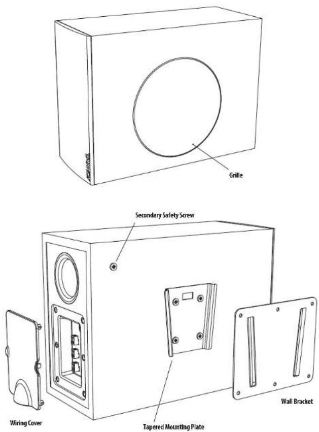
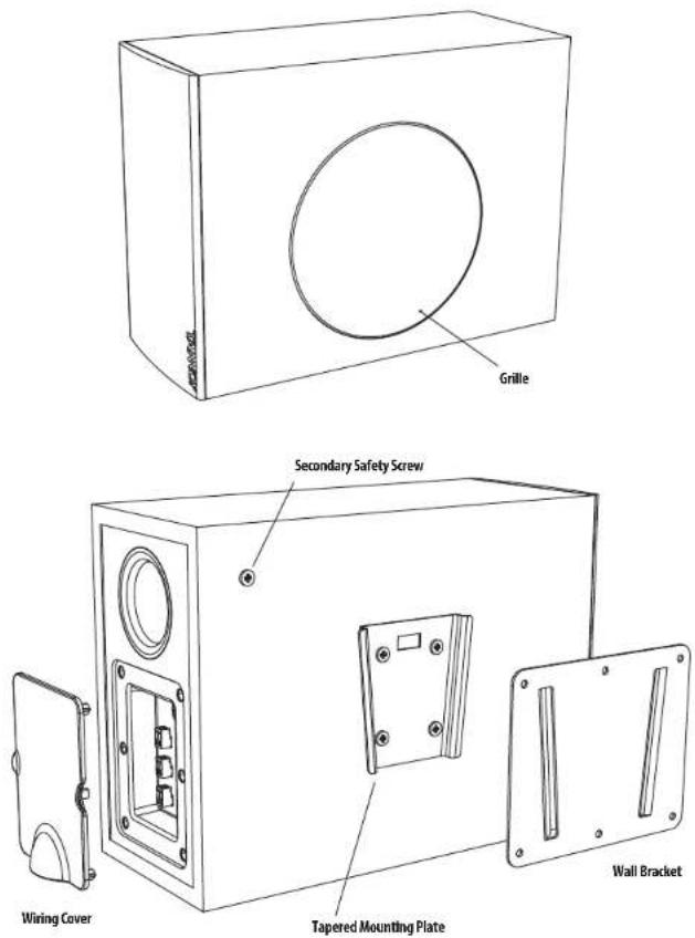
Some regional construction codes require the use of a secondary method of securing loudspeakers to provide the security of a backup support. A secondary support line should be attached from the secondary safety screw provided on the rear of the subwoofer, to a strong source point on the wall.
Before installing the loudspeaker, please consult the relevant construction codes in your region.
When using a power driver to install the product it is essential to use the correct torque level settings to avoid over tightening and damage to the wall material.
TANNOY will not be held responsible for any damages caused by the improper installation of these loudspeakers.
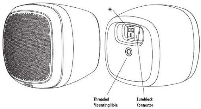
Product Feature Identification
SAT 3

Product Feature Identification SAT SUB
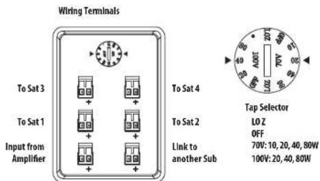
Wiring and Setting Up
Typical Hookup Diagrams
- Input Sources such as a paging microphone and media player can be connected to a preamplifier such as the LabGruppen CM41. Its line-level output connects to a power amplifier such as the LabGruppen CA2401.
- The speaker level output of the power amplifier connects to the Input connector on the SAT SUB subwoofer. See the next page for details of the connections.
- The SAT 3 satellite speakers connect to the outputs on the SAT SUB subwoofer terminal plate.

flowchart
graph TD
    A["Input 1"] --> B["Preamplifier"]
    C["Input 2"] --> B
    D["Micro"] --> A
    E["Media Player"] --> A
    F["Output Input"] --> G["Power Amplifier"]
    H["Sub Link to next SUB"] --> I["Satellites"]
    B --> J["Sub Station 3"]
    B --> K["Sub Station 4"]
    B --> L["Sub Station 1"]
    B --> M["Sub Station 2"]
    B --> N["Sub Station 3"]
    B --> O["Sub Station 4"]
    B --> P["Sub Station 1"]
    B --> Q["Sub Station 2"]
    B --> R["Sub Station 3"]
- If only 2 satellites are used, then only connect them to outputs 1 and 2 as shown.
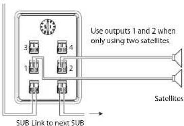
- The link output can be used to connect to the input of another subwoofer.
Terminal Connections
- WARNING: To avoid potential damage to your amplifier or loudspeaker, ensure that the amplifier is switched OFF prior to connecting or disconnecting any cables.
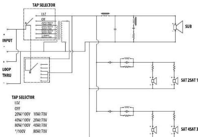
- Before switching the amplifier ON, double check that all connections are secure and that the polarity is correct, and check that the Tap Selector switch on the subwoofer is set correctly to match your power amplifier.
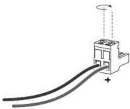
- The speaker wires are attached to the screw terminals of Euroblock connectors, and not to the subwoofer and satellite loudspeakers.
- The mounting brackets of the subwoofer and satellite speakers can be preinstalled and the Euroblock connectors wired up, and the subwoofer and satellite speakers added at a later stage.
- The two screw terminals of the Euroblock connectors are marked positive (+) and negative (-).
- Strip off approximately 8 mm (1/4") of the outer protective layer of one conductor and twist its inner cores together to prevent shorting from stray wires. Insert the core into the screw terminal of the Euroblock connector, while ensuring that correct polarity is maintained. Repeat this for both speaker wires. Gently pull on the wires to verify they are making a secure connection.
natural_image
Pure electrical circuit lines without any symbolsSAT SUB Subwoofer Installation
- WARNING: To avoid potential damage to your amplifier or loudspeaker, ensure that the amplifier is switched OFF prior to connecting or disconnecting any cables.
- The procedure below describes the installation of the SAT SUB subwoofer into a typical stud wall with drywall/plasterboard.
- Locate a suitable mounting position for the SAT SUB subwoofer within the room, that is practical and will give good audio performance. You can try connecting and operating the system with the SAT SUB located in various room positions to find the best performance.
- Use a stud-finder to locate a suitable nearby stud and mark this position. WARNING: Make sure that there are no power lines, other cables, or plumbing such as water, sewer, gas lines in the chosen location.
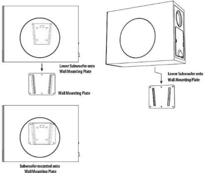
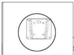
- The SAT SUB mounting bracket should be mounted to a stud. The screws must be long enough to enter into the wood and make a secure and safe mounting position. Make sure that the center top and center bottom mounting holes are used to attach to the stud. Check that the plate is level (and the right way up).
- For the other mounting holes not over a stud, suitable screws and wall plugs must be used to make a secure and safe mounting position. All mounting holes must be used. Consult the relevant construction codes in your region.

Wall Mounting Plate Centered on Stud
- If the mounting bracket is to be mounted to drywall (not over a stud), or on a solid masonry wall, then suitable screws and wall plugs must be used to make a secure and safe mounting position. Consult the relevant construction codes in your region.
- Run the speaker wire from your amplifier to this location, leaving enough slack to allow for the connection. Follow the information on the previous pages to connect the speaker wires from your power amplifier to the Euroblock connector.
- If it will be some time before the SAT SUB subwoofer is installed, cover the mounting bracket and any wiring to prevent any dust, moisture, or paint from entering.
-
The SAT SUB subwoofer is provided with an attachment point for a secondary safety cable. This will reduce the chance of the SAT SUB from coming off the wall during an earthquake. Connect up your safety cable to the SAT SUB before mounting it to the wall.
-
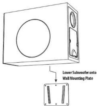
When ready, carefully align the mounting bracket attached to the SAT SUB subwoofer with the mounting plate on the wall, and lower into position.
- Open the cover to the wiring terminals, and connect the Euroblock connector from the power amplifier. If the SAT 3 satellites are installed, connect their Euroblock connectors as well.
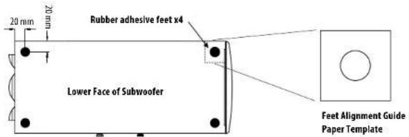
SAT SUB Floor Installation
- Four self-adhesive rubber feet are provided in case the SAT SUB subwoofer is to be used in a standing position, and not mounted to a wall. Press each foot securely in each corner of the bottom, using the supplied paper positioning template as a guide. Make sure the surface is clean and dry before pressing the feet in place.
SAT 3 Satellite Installation
- WARNING: To avoid potential damage to your amplifier or loudspeaker, ensure that the amplifier is switched OFF prior to connecting or disconnecting any cables.
- The procedure below describes the installation of the SAT 3 satellite into a typical wall or ceiling with drywall/plasterboard.
- Locate a suitable mounting position for the SAT 3 satellite within the room, that is practical and will give good audio coverage and performance.
- Use a stud-finder to locate a suitable nearby stud or ceiling joist and mark this position. WARNING: Make sure that there are no power lines, other cables, or plumbing such as water, sewer, gas lines in the chosen location.
- The SAT 3 mounting bracket should be mounted to a wall stud or ceiling joist. The screws must be long enough to enter into the wood and make a secure and safe mounting position. Make sure that at least two mounting holes are used to attach to the stud. Check that the mounting bracket is level.
- For the other mounting holes not over a stud, suitable screws and wall plugs must be used to make a secure and safe mounting position. All mounting holes must be used. Consult the relevant construction codes in your region.
- If the mounting bracket is to be mounted to drywall (not over a stud or joist), or on a solid masonry wall, then suitable screws and wall plugs must be used to make a secure and safe mounting position. Consult the relevant construction codes in your region.
- Run the speaker wire from your SAT SUB subwoofer to this location, leaving enough slack to allow for the connection. Follow the information on the previous pages to connect the speaker wires to the SAT 3 Euroblock connector.
- If it will be some time before the SAT 3 satellite is installed, cover the mounting bracket and any wiring to prevent any dust, moisture, or paint from entering.
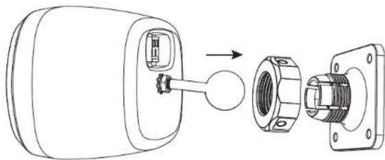
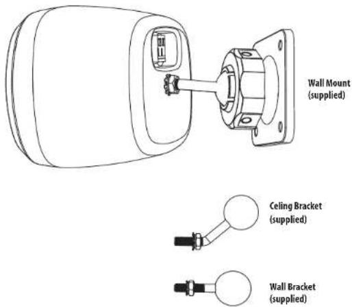
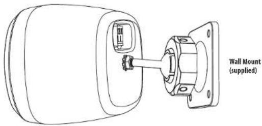
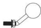
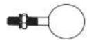
- If the SAT 3 is being mounted to a wall, attach the straight mounting arm to the rear threaded hole, and tighten with a wrench. For ceiling mounting, use the bent mounting arm instead.
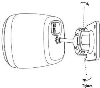
- When the bracket is securely mounted to the wall or ceiling, undo the large nut and press the ball end of the mounting arm into the bracket. Press the arm firmly in place, and tighten the nut to secure the SAT 3 at the desired angle.
natural_image
Technical line drawing of a mechanical assembly showing a cylindrical component inserted into a housing with a separate flange (no text or symbols present)24 25 Quick Start Guide SAT SUB and SAT 3
- Tighten the nut securely by using a small screwdriver or bar in any of the three holes in the circumference of the nut. (The hole diameter is 4.7 mm [0.185 inches].)
natural_image
Technical line drawing of a mechanical assembly with labeled parts, showing a shaft and housing (no text or symbols present)System Testing
- Check the wiring from the power amplifier to the SAT SUB subwoofer.
- Check the wiring from the SAT SUB subwoofer to the SAT 3 satellites.
- Check that the SAT SUB subwoofer Tap Selector is set correctly for your power amplifier and your system design.
- Turn on the preamplifier first, and turn down the system volume.
- Turn on the power amplifier.
- Play your source material and adjust the volume slowly to the desired level.
- Check that each loudspeaker is playing correctly.
- In general use, turn on the preamplifier first, before the power amplifier, and when shutting down, turn off the power amplifier first, before the preamplifier. This will reduce the chance of turn-on and turn-off "thumps" being heard in your system.
Introducción
natural_image
Pure electrical circuit lines without any symbols• All 6 mounting holes are used
• Center the mounting plate over the stud
- Wall plugs are used when not over the stud
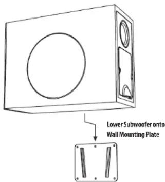

Subwoofer mounted onto Wall Mounting Plate
natural_image
Technical line drawing of a mechanical assembly showing a component being inserted into a housing (no text or symbols present)natural_image
Technical line drawing of a mechanical assembly with labeled 'Tighten' component (no other text or symbols)Prueba del sistema

natural_image
Pure electrical circuit lines without any symbolsWall Mounting Plate Centered on Stud
Installation du satellite SAT 3
natural_image
Technical line drawing of a mechanical device showing internal components and assembly (no text or symbols)natural_image
Technical line drawing of a mechanical assembly with labeled parts (no text or symbols)Test du système
44 SAT SUB and SAT 3
Quick Start Guide
natural_image
Pure electrical circuit lines without any symbolsInstallation des SAT SUB Subwoofers
• All 6 mounting holes are used
- Center the mounting plate over the stud
- Wall plugs are used when not over the stud

SAT 3 Satelliteninstallation
natural_image
Technical line drawing of a mechanical assembly showing internal components and a directional arrow (no text or symbols)natural_image
Technical line drawing of a mechanical assembly with labeled 'Tighten' component (no other text or symbols)Systemtests

natural_image
Pure electrical circuit lines without any symbolsnatural_image
Technical line drawing of a mechanical device showing internal components and assembly (no text or symbols)natural_image
Technical line drawing of a mechanical assembly with labeled parts (no text or symbols)Teste de Sistema
62 SAT SUB and SAT 3
Quick Start Guide
63
natural_image
Pure electrical circuit lines without any symbols• All 6 mounting holes are used
• Center the mounting plate over the stud
- Wall plugs are used when not over the stud


Subwoofer mounted onto Wall Mounting Plate
natural_image
Technical line drawing of a mechanical device showing internal components and assembly (no text or symbols)natural_image
Technical line drawing of a mechanical assembly with labeled 'Tighten' component (no other text or symbols)Test di sistema
- All 6 mounting holes are used
• Center the mounting plate over the stud
- Wall plugs are used when not over the stud
Satellietinstallatie SAT 3
natural_image
Technical line drawing of a mechanical assembly showing internal components and a directional arrow (no text or symbols)natural_image
Technical line drawing of a mechanical assembly with labeled parts, showing a shaft and housing (no text or symbols present)Systeemtesten
natural_image
Pure electrical circuit lines without any symbolsSAT SUB-subwooferinstallation
• All 6 mounting holes are used
• Center the mounting plate over the stud
- Wall plugs are used when not over the stud
SAT SUB Golvinstallation
SAT 3 satellitinstallation
natural_image
Technical line drawing of a mechanical assembly showing a component being inserted into a housing (no text or symbols present)natural_image
Technical line drawing of a mechanical assembly with labeled 'Tighten' component (no other text or symbols)Systemtestning
Celing Bracket (supplied)
Wall Bracket (supplied)
• All 6 mounting holes are used
• Center the mounting plate over the stud
- Wall plugs are used when not over the stud
natural_image
Technical line drawing of a mechanical assembly showing internal components and a directional arrow (no text or symbols)natural_image
Technical line drawing of a mechanical assembly with labeled parts, showing a tightening mechanism (no text or symbols present)Testowanie systemu
100 SAT SUB and SAT 3
Quick Start Guide 101
配線とセットアップ
典型的な接続図
natural_image
Pure electrical circuit lines without any symbols102 SAT SUB and SAT 3
Quick Start Guide 103
Subwoofer mounted onto Wall Mounting Plate
104 SAT SUB and SAT 3
Quick Start Guide 105
SAT 3 衛星の設置
natural_image
Technical line drawing of a mechanical assembly showing internal components and a circular component (no text or symbols)natural_image
Technical line drawing of a mechanical assembly with labeled parts, showing a fastener and tightening mechanism (no text or symbols present)システムテスト
106 107 Quick Start Guide SAT SUB and SAT 3
介绍

108 109 Quick Start Guide SAT SUB and SAT 3
产品特征识别
SAT SUB
接线和设置
典型的连接图
110 111 Quick Start Guide SAT SUB and SAT 3
终端连接
112 113 Quick Start Guide SAT SUB and SAT 3
SAT 3 卫星安装
natural_image
Technical line drawing of a mechanical assembly showing internal components (no text or symbols)114 115 Quick Start Guide SAT SUB and SAT 3
natural_image
Technical line drawing of a mechanical assembly with labeled 'Tighten' component (no other text or symbols)系统测试
SAT 3 with Ceiling Bracket
![157.5 [6.20] 65.0 [2.56] 100.0 [3.94] 93.0 [3.66] 100.0 [3.94] 47.0 [1.85] 47.0 [1.85] 4x Ø5.0 [0.197] All Dimensions are mm [Inches]](/content/2026/04/694294/images/391472bbdb9e2a7b6aabe637d022ee33b759bdc11390a96a47b69bd694b7443f.jpg)
116 117 Quick Start Guide SAT SUB and SAT 3
Dimensions
SAT 3 with Wall Bracket
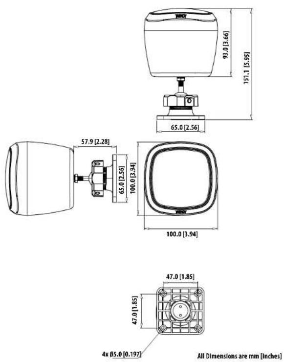
Dimensions
SAT SUB
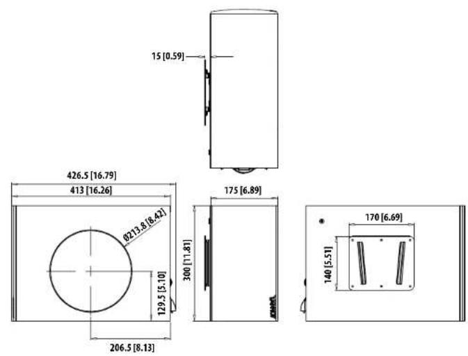
All Dimensions are mm [inches]
118 SAT SUB and SAT 3
EN Block Diagram
Quick Start Guide 119
Specifications
EN
| SAT 3 | SAT SUB | |
| Performance | ||
| Frequency response (-10 dB) | 200 Hz -20 kHz | 32 Hz - 260Hz |
| Sensitivity 1 W/ 1m | 83 dB | 93 dB |
| Power handling | ||
| Average | 15 W | 80 W |
| Programme | 25 W | 120 W |
| Recommended amplifier power | 25 W @ 16 Ω | 120 W @ 8 Ω |
| Nominal Impedance | 16 Ω | 8 Ω |
| Maximum SPL @1 m | 100 dB | 116 dB |
| Transformer taps | NA | 100V; 20, 40, 80, 8 LoZ, 70V: 10, 20, 40, 80, 8 LoZ |
| Crossover point | NA | 200 Hz |
| Coverage angle @ 1 kHz | 265" horizontal, 265" vertical | |
| Transducers | ||
| Diameter/material/type | 63.5mm (2.5") Paper | 1 x 165 mm (6.5") Paper |
| Physical | ||
| Enclosure material | ABS | MDF |
| Grille material | Steel | Steel |
| Connectors | Phoenix Contact terminal block | Phoenix Contact terminal block x 6 |
| Dimensions (HxWxD) | 100 x 100 x 93 mm(speaker only,no bracket included) | 175 x 413 x 300 mm(speaker only, no bracket included) |
| Net weight | 1.16 kg (2.6 lbs)(bracket included) | 10.7 kg 23.5 lbs)(bracket included) |
| Included accessories | Ceiling mount bracket,wall mount bracket | wall mount bracket,4x rubber feet, and paper positioning template |
120 121 Quick Start Guide SAT SUB and SAT 3
Other important information Other important information

Important information As

ortantes

Informations importantes
1. Register online.
Please register your new Music Tribe equipment right after you purchase it by visiting musictribe.com. Registering your purchase using our simple online form helps us to process your repair claims more quickly and efficiently. Also, read the terms and conditions of our warranty, if applicable.
- Malfunction. Should your Music Tribe Authorized Reseller not be located in your vicinity, you may contact the Music Tribe Authorized Fulfiller for your country listed under "Support" at musictribe.com. Should your country not be listed, please check if your problem can be dealt with by our "Online Support" which may also be found under "Support" at musictribe.com. Alternatively, please submit an online warranty claim at musictribe.com BEFORE returning the product.
1. Registro online.
122 123 Quick Start Guide SAT SUB and SAT 3
Other important information

124 125 Quick Start Guide SAT SUB and SAT 3
CE
Hereby, Music Tribe declares that this product is in compliance
with Directive 2011/65/EU and Amendment 2015/863/EU,
Directive 2012/19/EU, Regulation S19/2012 REACH SVHC and
Directive 1907/2006/EC, and this passive product is not applicable.
to EMC Directive 2014/30/EU, LV Directive 2014/35/EU.
Full text of EU DoC is available at https://community.musictribe.com/
EU Representative: Music Tribe Brands DK A/S
Address: Gammel Strand 44, DK-1202 Kabenhavn K, Denmark
UK Representative: Music Tribe Brands UK Ltd.
Address: 6 Lloyds Avenue, Unit 4CL London EC3N 3AX, United Kingdom
EN