HR3610 - Fan PHILIPS - Free user manual and instructions
Find the device manual for free HR3610 PHILIPS in PDF.

| Brand | Philips |
| Model | HR3610 |
| Product type | Pedestal fan |
| Power supply | Mains, 220-240 V |
| Rated power | 50 W (estimated) |
| Speeds | 3 speeds + natural wind mode |
| Timer | 1, 2 or 4 hours |
| Oscillation | Yes (oscillation on/off control) |
| Height adjustment | Yes, sliding tube with unlock button |
| Airflow direction | Adjustable horizontal and vertical |
| Dimensions (max height) | Approx. 130 cm |
| Fan blade diameter | Approx. 40 cm (estimated) |
| Weight | Approx. 3.5 kg |
| Blade material | Plastic |
| Safety grille | Two grilles (front and rear) with closure clip |
| Noise level | Not specified |
| Care and cleaning | Unplug, clean with a soft dry or damp cloth and mild detergent |
| Safety | Do not immerse, do not insert objects, keep away from children, do not use in humid environments |
| Spare parts | Contact Philips or authorized service center for damaged cord |
| Repairability | Replacement of parts by professional |
| Included accessories | Screws, remote control (not for HR3610) |
| Warranty | Consult Philips terms |
Frequently Asked Questions - HR3610 PHILIPS
User questions about HR3610 PHILIPS
0 question about this device. Answer the ones you know or ask your own.
Ask a new question about this device
Download the instructions for your Fan in PDF format for free! Find your manual HR3610 - PHILIPS and take your electronic device back in hand. On this page are published all the documents necessary for the use of your device. HR3610 by PHILIPS.
USER MANUAL HR3610 PHILIPS
natural_image
Black outdoor fan with a circular grille and a stand, no visible text or symbols on the fan or background.English Page 4
- Keep pages 3 and 54 open when reading these operating instructions.
Français Page 8
English
Important
- Read the instructions in conjunction with the illustrations before using the first time.
- Before you connect the appliance, check if the voltage specified on the appliance corresponds to the mains voltage in your home.
- Never immerse any part of the appliance in water or any other liquid.
- Never put objects into the grille when the fan is connected to the mains.
- Keep a watchful eye on children. Never allow them to play with the fan.
- It is not advisable to expose people (especially babies and older people) to a continuous cold air stream for a long time.
- Do not use the fan in very hot or humid environments, such as bathrooms.
- Keep the fan away from lace curtains, plants etc.
- Do not connect the appliance to the mains voltage unless completely assembled and adjusted.
- If the mains cord of this appliance is damaged, it must only be replaced by Philips or their service representative, as special tools and/or parts are required.
General description (fig. 1, page 3)
A Clip
B Front grille
cHook
Blade cap
E Fan blade
F Plastic collar
G Positioning holes
H Rear grille
Oscillation knob
Positioning pins
Motor shaft
Motor unit
M Sliding pipe
N Extension release button
Fan stand
P Mains cord
Control Panel
R Base opening
s Fan base
T Screws
Remote control unit (For model HR 3615 only)
Assembly
- Ensure that the product is not connected to the mains when assembling.
- Insert the mains cord (P) through the base opening (R) of the fan base (S).
- Put the fan stand (O) inside the fan base (S) while pulling the mains cord (P) until it gives a "click" sound. Avoid the mains cord being pressed between the fan base and fan stand.
- Use a screwdriver to secure the fan stand with
two screws (T) provided.
- Unscrew the blade cap (D) from the motor shaft (K).
Please note: Unscrew clockwise.
- Remove the plastic protective tube from the motor shaft (K).
- Unscrew the plastic collar (F) from the motor unit (L) by turning the collar anti-clockwise.
- Mount the rear grille (H) onto the motor unit (L) by matching the three positioning holes (G) on the rear grille to the three positioning pins (J) on the front of the motor unit.
Push in firmly until the three positioning pins protrude through the three positioning holes.
- Secure the rear grille (H) to the motor unit (L) with the plastic collar (F).
- Insert the fan blade (E) onto the motor shaft (K) so that the flattened side of the central hole corresponds with the flattened side of the shaft. Press firmly until the fan blade stops.
Secure the fan blade with the blade cap (D), turning anti-clockwise to tighten.
- Test fan blade (E) operation by rotating it with your hand. There should be no friction with the plastic collar (F).
If the blade does not rotate freely, disassemble and repeat the procedures.
- Open the clip (A) by moving the clip downwards.
- Attach the front grille (B) to the rear grille (H) by positioning the hook (C).
- Join the two grilles by pressing firmly ("Click!").
- Secure the two grilles by moving the clip (A) upwards.
- You can store excess mains cord under the fan base (S) as illustrated in fig 2.
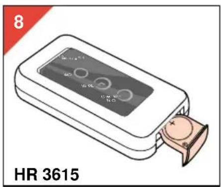
Battery (for type HR 3615 only)
- The remote control unit (U) operates on one CR2025 3V Lithium battery.
-
A battery is supplied inside the Remote Control Unit.
Please remove the paper cover before first use. -
Place the battery as shown in fig 8.
Ensure that the indication “+” corresponds to the indication in the appliance.
- Do not leave empty battery in the appliance. If you do not intend to use the appliance for a considerable time, remove the battery.
Batteries contain substances which may pollute the environment.
Please dispose of your old batteries at an officially assigned place.
Height setting
- Press the extension release button (N) and pull the sliding pipe (M) upwards or downwards to the desired height (fig. 3).
- Lock the sliding pipe (M) at its lowest position ("Click") before moving the fan.
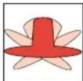
Oscillation
The fan will oscillate during operation when the oscillation knob (I) is in the down position. When the oscillation knob is in the up position, the fan does not oscillate (fig. 4).
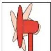
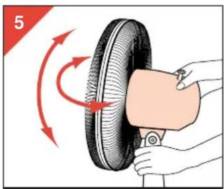
Free neck positioning
You can adjust the air stream direction in both horizontal and vertical direction.
- Horizontally: Pull the oscillation knob (I) upwards and turn the motor unit (L) to the desired direction (fig. 5).
In the same manner the area through which the fan oscillates can be adjusted.
You will hear a clicking sound while positioning.
- Vertically: Move the motor unit (L) upwards or downwards to alter the vertical angle (fig. 5).
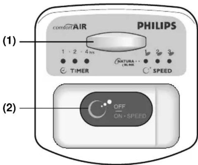
Control panel type HR 3610
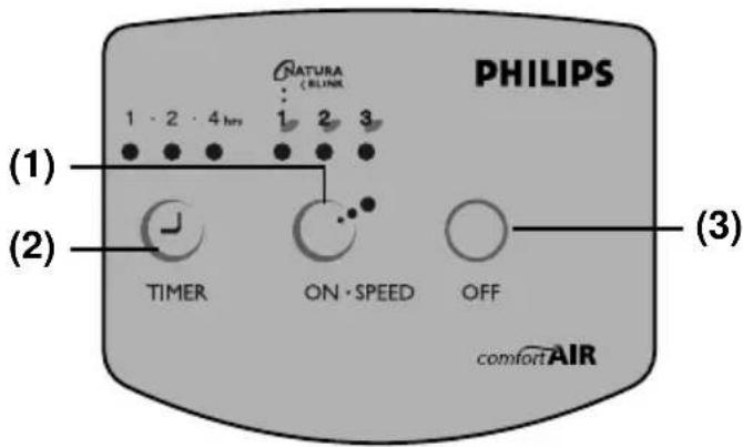
- Speed selection button
- Timer setting button
- Off button
Speed selection
- Press the "ON·SPEED" button once to switch on the fan at high speed. Pilot light "3" above the "ON·SPEED" button will come on.
- Press the "ON•SPEED" button twice to switch on the fan at medium speed. Pilot light "2" above the "ON•SPEED" button will come on.
- Press the "ON·SPEED" button three times to switch on the fan at low speed. Pilot light "1" above the "ON·SPEED" button will come on.
Natural Wind
- Press the "ON·SPEED" button four times for "Natural Wind". Pilot light "1" will blink.
The fan will change speed at a random pattern, producing comfortable natural wind.
- If you press the "ON·SPEED" button once more, the fan will go back to high speed again. You can change the speed during operation. The other controls can only be used if the fan is switched on (i.e. after pressing "ON·SPEED").
Timer setting
- Press the "TIMER" button once for automatic switching-off after one hour. Pilot light "1" above the "TIMER" button will come on.
- Press the "TIMER" button twice for automatic switching-off after two hours. Pilot light "2" above the "TIMER" button will come on.
- Press the "TIMER" button three times for automatic switching-off after four hours. Pilot light "4" above the "TIMER" button will
come on.
- To stop Timer function, press the button again and the pilot light goes out.
- You can change the timer setting during operation.
- As time elapses, the remaining time will light up.
Off
- Press "OFF" to switch off the fan. All function settings will be canceled including timer.
Control panel type HR 3615
1 Remote control receptor
2 Speed selection and on/off button
You can operate the fan either by the remote control unit or by the OFF/ON·SPEED button on the control panel.
Speed selection
- Press the "OFF/ON·SPEED" button once to switch on the fan at high speed. Pilot light "3" will come on.
- Press the "OFF/ON·SPEED" button twice to switch on the fan at medium speed. Pilot light "2" will come on.
- Press the "OFF/ON·SPEED" button three times to switch on the fan at low speed. Pilot light "1" will come on.
Natural Wind
- Press the "OFF/ON·SPEED" button four times for "Natural Wind". Pilot light "I" will blink.

The fan will change speed at a random pattern, producing comfortable natural wind.
- Press the "OFF/ON·SPEED" button once more for switching off the fan.
All function settings will be canceled, including timer. - The timer can only be set by means of the Remote Control Unit (U).
Remote Control Unit type HR 3615
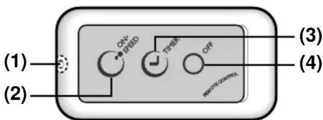
1 Infra red transmitter
2 Speed selection button
3 Timer setting button
4 Off button
- The buttons of the remote control unit (U) have the same symbols and functions as the corresponding buttons on the control panel of type HR 3610.
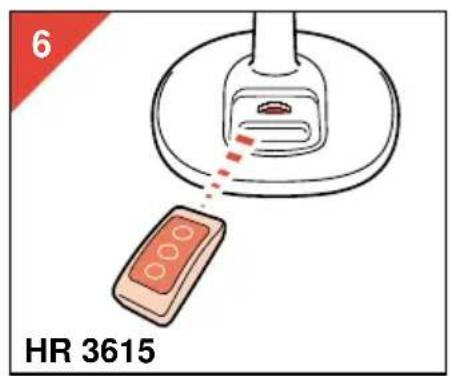
Please refer to section "Control panel type HR 3610" on page 5. - Please direct the Infra Red Transmitter towards the Remote Control Receptor on the control panel while pressing the buttons.
Ensure that there is no obstruction between transmitter and the receptor (fig 6).
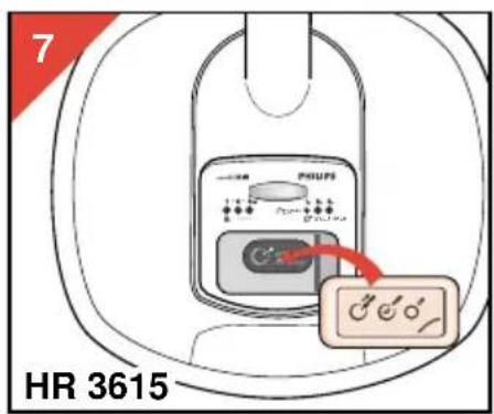
The maximum effective distance between the transmitter and the remote control receptor is 3 m. - You can also operate the remote control unit (U) when it is put inside the control panel as illustrated in fig. 7.
Storage
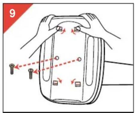
The fan can be disassembled for compact storage:
- For the fan grilles (B, H) and fan blade (E), reverse the assembly procedures on page 4.
- For the detachable fan base (S), first untighten the two screws (T) on the bottom of the fan base with a screw driver.
Then press the four clips in the direction as illustrated in fig. 9 and pull the fan stand (0) out carefully.
Cleaning
- Always remove the plug from the mains socket before cleaning.
- Clean with a soft dry or damp cloth, if required with a soapy detergent.
- Do not use abrasives or solvents.
For U.K. only:
Fitting a different plug
This appliance is fitted with a BS 1363 13 Amp. plug.
Should you need to replace the plug, connect the wires as follows:
Green/yellow wire to the Earth terminal ( ± ) of the new plug.
Brown wire to the Live (L) terminal of the new plug.
Blue wire to the Neutral (N) terminal of the new plug.
Always fit the same value of fuse as that originally supplied with your appliance.
Only use BS 1362 approved fuses.
As a guide only: Appliances under 700 W can have a 3 Amp. fuse (red) and all others should have a 13 Amp. fuse (brown).
When disposing of an old plug (particularly the moulded type which has been cut from the mains cord) always remove the fuse as the plug could be dangerous if ever inserted in a live socket.
Français
Important
natural_image
Simple line drawing of a mechanical component with a spring attached, no text or symbols present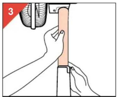
natural_image
Illustration of hands performing a manual task on a vertical support structure (no text or symbols present)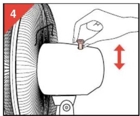
natural_image
Illustration of a hand using a tool to lift a tire, showing red motion arrows (no text or symbols)