DW721KN - Saw DEWALT - Free user manual and instructions
Find the device manual for free DW721KN DEWALT in PDF.

User questions about DW721KN DEWALT
0 question about this device. Answer the ones you know or ask your own.
Ask a new question about this device
Download the instructions for your Saw in PDF format for free! Find your manual DW721KN - DEWALT and take your electronic device back in hand. On this page are published all the documents necessary for the use of your device. DW721KN by DEWALT.
USER MANUAL DW721KN DEWALT
English (original instructions)
natural_image
Technical line drawing of a mechanical assembly with no visible text or symbols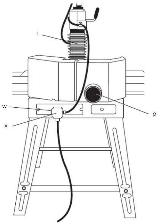
text_image
i w x pFigure 2
natural_image
Technical line drawing of a mechanical assembly with no visible text or symbolsFigure 3
text_image
g yFigure 4
text_image
y fFigure 5
natural_image
Technical line drawing of a mechanical device with labeled component 'Z' (no text or symbols beyond label)Figure 6
natural_image
Technical line drawing of a mechanical device with springs and a labeled component (Z), no readable text or symbols present.Figure 7
natural_image
Line drawing of a hand using a tool to adjust or install a component, with no visible text or symbols.Figure 8
natural_image
Mechanical assembly diagram showing a clamping device with coil spring and housing (no text or symbols)Figure 9
natural_image
Technical line drawing of a mechanical device with coiled spring and housing (no text or symbols)Figure 10
text_image
bb ccFigure 11
text_image
e ddFigure 12
text_image
e tFigure 13
natural_image
Line drawing of a hand holding a pencil, with a diagonal line and a small mark on the left (no text or symbols)Figure 14
natural_image
Simple line drawing of a cylindrical object and two parallel lines with an oval mark (no text or symbols)Figure 15
text_image
s1Figure 16
natural_image
Technical line drawing of a mechanical assembly with no visible text or symbolsFigure 17
natural_image
Line drawing of a hand holding a screwdriver next to a metal plate (no text or symbols)Figure 18
natural_image
Line drawing of a hand using a tool to adjust or install a component, with no visible text or symbols.Figure 19
natural_image
Line drawing of a hand using a tool to cut a component, no text or symbols presentFigure 20
natural_image
Pure technical line drawing of a mechanical assembly without any text, numbers, or symbolsFigure 21
text_image
gg ffFigure 22
text_image
hh iiFigure 23
text_image
W jj xFigure 24

text_image
Technical diagram showing a hand operating a mechanical device with labeled parts 'l' and 'm'Figure 25
text_image
d kkFigure 26
natural_image
Technical line drawing of a mechanical device with hands operating it (no text or symbols present)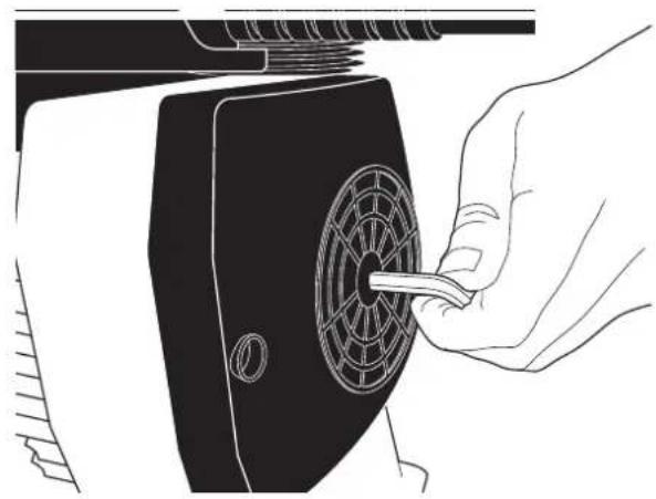
natural_image
Line drawing of a hand inserting a component into a device with a fan-like structure (no text or symbols)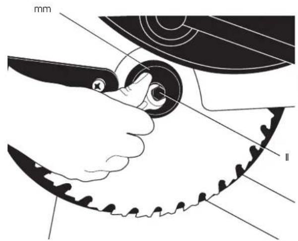
text_image
mm IIFigure 27
natural_image
Technical line drawing of a mechanical assembly with labeled components (no readable text or symbols)Figure 28
text_image
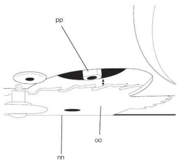
pp oo nnFigure 29
natural_image
Illustration of a hand operating a machine with a tool, no visible text or symbolsFigure 30
text_image
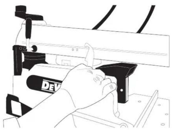
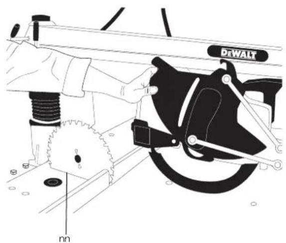
DEWALT nnFigure 31
text_image
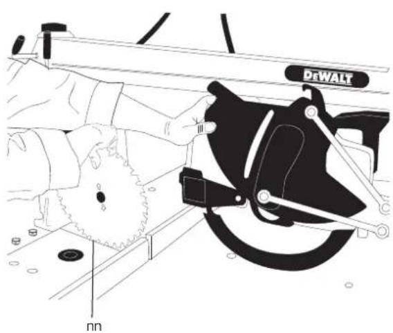
DeWALT nnFigure 32
natural_image
Technical diagram of a mechanical gear assembly with labeled component 'bb' (no text or symbols beyond label)Figure 33
natural_image
Technical line drawing of a DeWALT industrial machine with no visible text or symbols on the device itselfFigure 34
text_image
Diagram illustrating fluid flow with labeled components and directional arrows, including symbols like 'e' and '∞'Figure 35
natural_image
Technical line drawing of a mechanical assembly with no visible text or symbolsFigure 36
text_image
tt ss UUFigure 37
natural_image
Technical line drawing of a mechanical device with a dial and handle (no text or symbols)Figure 38
natural_image
Technical line drawing of a mechanical machine with a gear and mounting base, showing motion direction (no text or symbols)Figure 39
text_image
v v j kFigure 40
natural_image
Technical diagram of a vehicle suspension system with hoses and springs (no text or labels)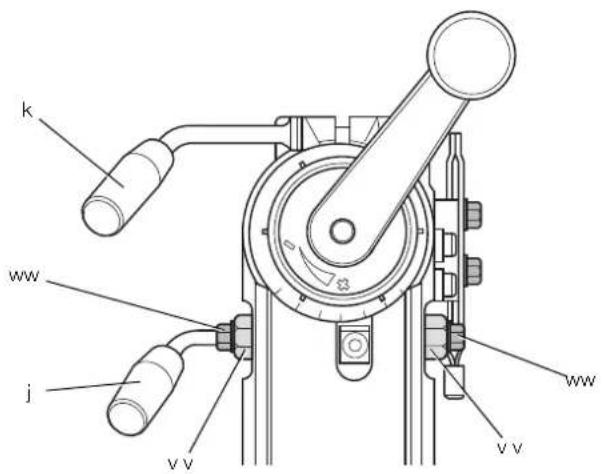
text_image
k ww j vv vv wwFigure 42Figure 41
text_image
yy zz xxFigure 43
text_image
a1 c a2 dFigure 44
text_image
a4 u uu ssFigure 45
text_image
k j m a2Figure 46
text_image
Technical diagram of a mechanical assembly with labeled parts (k, i, m)Figure 47
natural_image
Technical line drawing of a mechanical assembly with spring and frame components (no text or symbols)Figure 48
text_image
a4 a3 u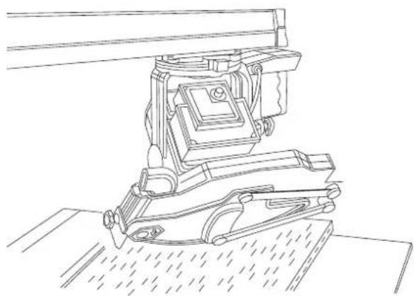
natural_image
Technical line drawing of a mechanical device with no visible text or symbolsFigure 50 Figure 49
natural_image
Technical line drawing of a mechanical assembly with a curved component and a labeled part 'a5' (no text or symbols beyond label)Figure 51
natural_image
Technical line drawing of a mechanical assembly with no visible text or symbolsFigure 52
text_image
a6 a6DW721KN
text_image
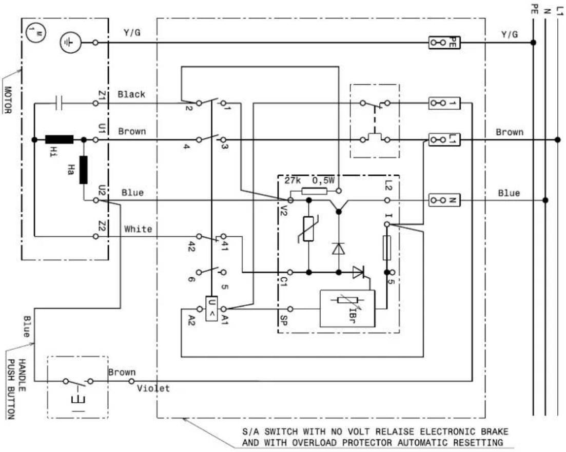
MOTOR Y/G Z1 U1 Black Brown H1 Ha U2 Blue White Z2 42 41 6 5 A2 U< A1 C1 SP IBr 27k 0.5W V2 L2 I Blue N PE Y/G L1 Brown Blue HANDLE PUSH BUTTON Brown Violet S/A SWITCH WITH NO VOLT RELAISE ELECTRONIC BRAKE AND WITH OVERLOAD PROTECTOR AUTOMATIC RESETTINGDW722KN
text_image
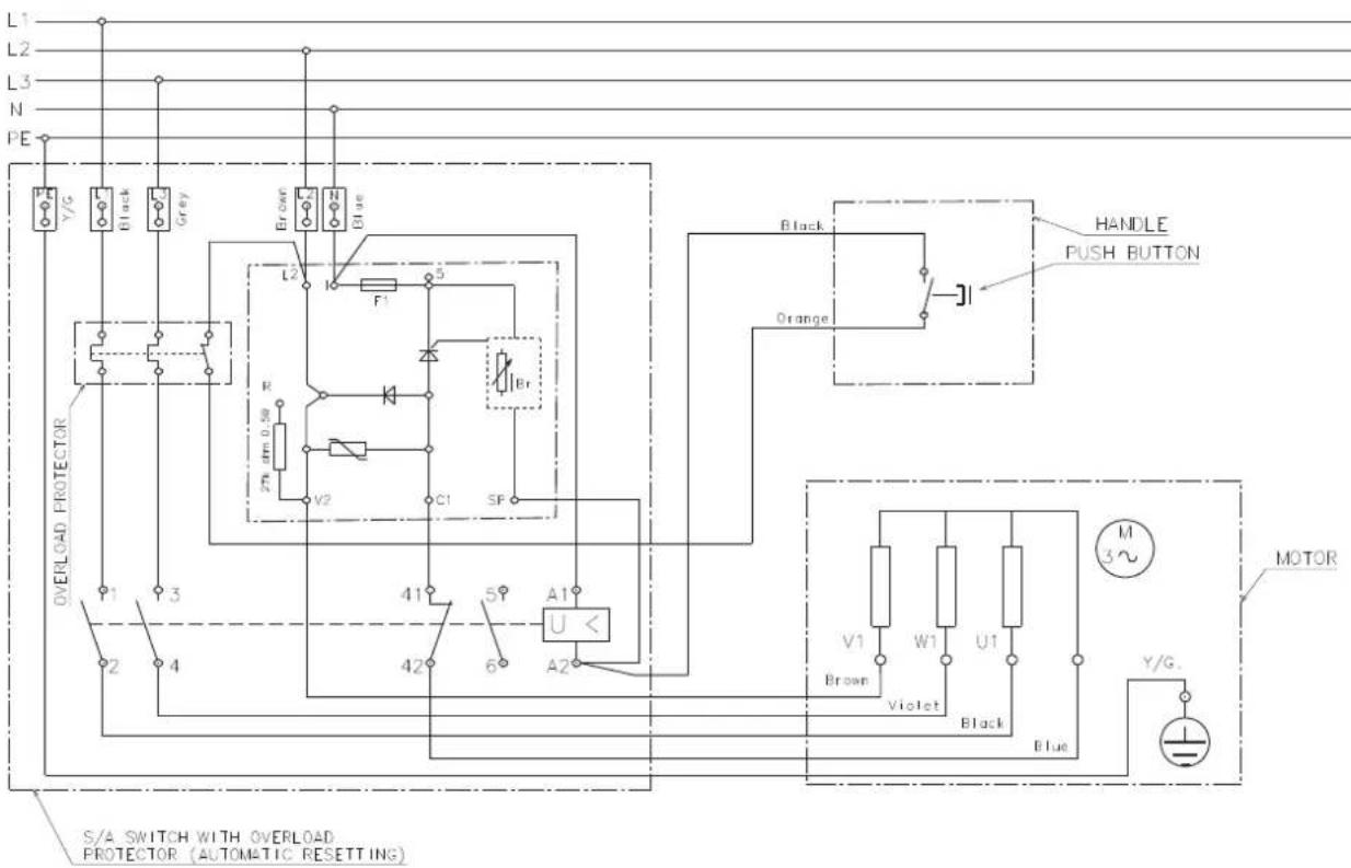
L1 L2 L3 N PE Y/G Black Grey Brown N Blue L2 F1 5 R V2 C1 SP Br OVERLOAD PROTECTOR Y1 Y3 2 4 41 5Y A1 U < 42 6 A2 BLACK ORANGE HANDLE PUSH BUTTON MOTOR V1 W1 U1 M Brown Violet Black Blue Y/G S/A SWITCH WITH OVERLOAD PROTECTOR (AUTOMATIC RESETTING)RADIALARMSAW
DW721KN, DW722KN
Tillykke!
RADIALARMSÄGE DW721KN, DW722KN
D-65510, Idstein, Germany
15.06.2009

1 Doppelmaulschlüssel 10/13 mm
RADIAL ARM SAW DW721KN, DW722KN
Congratulations!
You have chosen a DEWALT power tool. Years of experience, thorough product development and innovation make DEWALT one of the most reliable partners for professional power tool users.
Technical Data
| DW721KN | DW722KN | ||
| Power input W | 2000 3000 | ||
| Power output W | 1580 2280 | ||
| Type | 2 | 1 | |
| Voltage | V | 230 | 400 |
| Blade diameter | mm | 300 | 300 |
| Blade bore | mm | 30 | 30 |
| Spindle diameter | mm | 20 | 20 |
| No-load speed, 50 Hz | min^1 | 3000 | 3000 |
| Load speed, 50 Hz | min^-1 | 2760 | 2650 |
| No-load speed, 60 Hz | min^1 | 3600 | - |
| Load speed, 60 Hz | min^-1 | 3380 | - |
| Depth of cut at 90° | mm | 90 | 90 |
| Max. crosscut capacity at 0° | mm | 507 | 507 |
| Max. mitre cut capacity at 45° | |||
| right hand | mm | 342 | 342 |
| left hand | mm | 172 | 172 |
| Depth of cut at 45° | mm | 60 | 60 |
| Max. crosscut capacity at 0° | mm | 507 | 507 |
| Max. mitre cut capacity at 45° | |||
| right hand | mm | 247 | 247 |
| left hand | mm | 272 | 272 |
| Overall dimensions (with legstand) | cm | 176 x 122 x 77 | 176 x 122 x 77 |
| cm | 176 x 122 x 147 | 176 x 122 x 147 | |
| Dust extraction adapter | mm | 100 | 100 |
Recommended dust extraction values
| Air velocity at the point of connection | m/s | 20 | 20 |
| Volume metric flow | m^3/h | 500 | 500 |
| Vacuum value at the point of connection | PA | 5000 | 2400 |
| Dust extraction port | mm | 100 | 100 |
| Cross area section | cm^2 | 78.5 | 78.5 |
| Dust extraction port | mm | 40 | 40 |
| Cross area section | cm^2 | 12.6 | 12.6 |
| Weight | kg | 115 | 115 |
| Automatic blade brake time | <10s | <10s | |
| Duty cycle | min | 1'/3' | 1'/3' |
| Protection grade | IP5X | IP5X |
Vibration total values (triax vector sum) determined according to EN 61029-1:
| L_in | (sound pressure) dB(A) | 96.5 | 96.5 | |
| K_in | (sound pressure uncertainty) | dB(A) | 3.0 | 3.0 |
| L_out | (sound power) | dB(A) | 109.5 | 109.5 |
| K_out | (sound power uncertainty) | dB(A) | 3.3 | 3.3 |
Vibration total values (triax vector sum) determined according to EN 61029-1:
| Vibration emission value a | _h = m/s^3 | 2.0 | 2.0 |
| Uncertainty K = | m/s^3 | 1.5 | 1.5 |
NOTE: The figures are emission levels and are not necessarily safe working levels. Whilst there is a correlation between the emission and exposure levels, this cannot be used reliably to determine whether or not further precautions are required. Factors that influence the actual level of exposure of the workforce include the characteristics of the workroom and the other sources of noise, etc. i.e. the number of machines and other adjacent processes. Also, the permissible exposure level can vary from country to country. This information, however, will enable the user of the machine to make a better evaluation of the hazard and risk.
| Fuses: | ||
| Europe | 230 V tools | 16 Amperes, mains |
| 400 V tools | 16 Amperes, per phase | |
Definitions: Safety Guidelines
The definitions below describe the level of the severity for each signal word. Please read the manual and pay attention to these symbols.

DANGER: indicates an imminently hazardous situation which, if not avoided, will result in death or serious injury.

WARNING: indicates a potentially hazardous situation which, if not avoided, could result in death or serious injury.

CAUTION: indicates a potentially hazardous situation which, if not avoided, may result in minor or moderate injury.
NOTICE: Indicates a practice not related to personal injury which, if not avoided, may result in property damage.

Denotes risk of electric shock.

Denotes risk of fire.

Denotes sharp edges.
EC-Declaration of Conformity
MACHINERY DIRECTIVE

DW721KN, DW722KN
DEWALT declares that these products, described under "technical data" are in compliance with: 2006/42/EC, EN 1870-17:2007.
These products also comply with Directive 2004/108/EC. For more information, please contact DEWALT at the address or refer to the back of the manual.
The undersigned is responsible for compilation of the technical file and makes this declaration on behalf of DEWALT

text_image
X. JopmanHorst Grossmann
Vice President Engineering and Product Development
D-65510, Idstein, Germany
15.06.2009

WARNING: to reduce the risk of injury, read the instruction manual.
General Safety Instructions

WARNING! When using electric tools basic safety precautions should always be followed to reduce the risk of fire, electric shock and personal injury including the following.
Read all of these instructions before attempting to operate this product and save these instructions.
SAVE THIS MANUAL FOR FUTURE REFERENCE
1. Keep work area clear.
Cluttered areas and benches invite injuries.
2. Consider work area environment.
Do not expose the tool to rain. Do not use the tool in damp or wet conditions. Keep the work area well lit (250 - 300 Lux). Do not use the tool where there is a risk of causing fire or explosion, e.g. in the presence of flammable liquids and gases.
3. Guard against electric shock.
Avoid body contact with earthed surfaces (e.g., pipes, radiators, cookers and refrigerators). When using the tool under extreme conditions (e.g., high humidity, when metal swarf is being produced, etc.), electric safety can be improved by inserting an isolating transformer or a (FI) earth-leakage circuit-breaker.
4. Keep other persons away.
Do not let persons, especially children, not involved with the work, touch the tool or the extension cord and keep them away from the work area.
5. Store idle tools.
When not in use, tools must be stored in a dry place and locked up securely, out of reach of children.
6. Do not force the tool.
It will do the job better and safer at the rate to which it was intended.
7. Use the right tool.
Do not force small tools to do the job of a heavy duty tool. Do not use tools for purposes not intended; for example do not use circular saws to cut tree limbs or logs.
8. Dress properly.
Do not wear loose clothing or jewellery, as these can be caught in moving parts. Non-skid footwear is recommended when working outdoors. Wear protective hair covering to contain long hair.
9. Use protective equipment.
Always use safety glasses. Use a face or dust mask if working operations create dust or flying particles. If these particles might be considerably hot, also wear a heat-resistant apron. Wear ear protection at all times. Wear a safety helmet at all times.
10. Connect dust extraction equipment.
If devices are provided for the connection of dust extraction and collection facilities, ensure that these are connected and properly used.
11. Do not abuse the cord.
Never yank the cord to disconnect if from the socket. Keep the cord away from heat, oil and sharp edges. Never carry the tool by its own cord.
12. Secure work.
Where possible use clamps or a vice to hold the work. It is safer than using your hand and it frees both hands to operate the tool.
13. Do not overreach.
Keep proper footing and balance at all times.
14. Maintain tools with care.
Keep cutting tools sharp and clean for better and safer performance. Follow instructions for lubricating and changing accessories. Inspect tools periodically and if damaged have them repaired by an authorised service facility. Keep handles dry, clean and free from oil and grease.
15. Disconnect tools.
When not in use, before servicing and when changing accessories such as blades, bits and cutters, disconnect tool from the power supply.
16. Remove adjusting keys and wrenches.
Form the habit of checking to see that adjusting keys and wrenches are removed from the tool before operating the tool.
17. Avoid unintentional starting.
Do not carry the tool with a finger on the switch. Be sure that the tool is in the "off" position before plugging in.
18. Use outdoor extension leads.
Before use, inspect the extension cable and replace if damaged. When the tool is used outdoors, use only extension cords intended for outdoor use and marked accordingly.
19. Stay alert.
Watch what you are doing. Use common sense. Do not operate the tool when you are tired or under the influence of drugs or alcohol.
20. Check for damaged parts.
Before use, carefully check the tool and mains cable to determine that it will operate properly and perform its intended function. Check for alignment of moving parts, binding of moving parts, breakage of parts, mounting and any other conditions that may affect its operation. A guard or other part that is damaged should be properly repaired or replaced by an authorized service centre unless otherwise indicated in this instruction manual. Have any damaged or defective switches replaced by an authorised service center. Do not use the tool if the switch does not turn it on and off. Never attempt any repairs yourself.

WARNING! The use of any accessory or attachment or performance of any operation with this tool other than those recommended in this instruction manual may present a risk of personal injury.
21. Have your tool repaired by a qualified person.
This electric tool complies relevant safety rules. Repairs should only be carried out by qualified persons using original spare parts; otherwise this may result in considerable danger to the user.
Additional Safety Rules for Radial Arm Saws
- Protect the electric power supply with a suitable fuse or circuit breaker.
- Keep the bearing tracks in the arm and the bearings on the roller head assembly clean and free from grease.
- Before turning the saw on, make sure that the fence is in the correct position. The blade should not contact the material until the saw is pulled by the handle.
- Always set the finger guard so that it passes above the fixed fence or is 3 mm above the surface of the material being cut, whichever is higher.
- Regularly check the adjustments for accuracy and adjust as required.
- Make sure that the blade rotates in the correct direction and that the teeth are pointing towards the fence.
- Make sure all clamp handles are tight before starting operation.
- Never run the machine without all guards in place.
- When not in use, protect the saw blade completely using the blade guard.
- When not in use, when changing blades or carrying out maintenance, disconnect the machine from the power supply.
- Always use correct, sharpened saw blades manufactured in accordance with EN847-1 and with a rake angle of +/- 5 mm.
- Never use saw blades where the maximum marked speed is lower than the revolution speed of the spindle.
- Do not use HSS (high-speed steel) saw blade.
• The recommended blade diameter is stated in the technical data.
- Do not wedge anything against the motor fan to hold the motor shaft.
- Before use, ensure the guards, brake, automatic return and locking devices are functioning properly. Do not use the machine if these devices are defective.
- When sawing a round workpiece ALWAYS use suitable jig or prism to prevent rotation of the workpiece.
- Do not force the cutting action. (Stalling or partial stalling of the motor can cause major damage.) Allow the motor to reach full speed before cutting.
- Do not lift the machine by its worktable.
- Do not cut ferrous metals, non-ferrous metals or masonry.
- Do not apply lubricants to the blade when it is running.
- Do not place either hand in the blade area when the saw is connected to the power source.
- Do not reach around behind the saw blade when in use.
- Do not place hands closer than 150 mm from the saw blade while cutting.
- Do not use damaged or cracked saw blades.
- Replace the fence if damaged and/or no longer offers proper support. The fence needs to be replaced periodically.
- ALWAYS ensure safe operation. The radial arm saws needs to be fixed to the floor with diameter 8 mm bolts with a minimum length of 80 mm.

WARNING! When cutting round workpiece it is necessary to secure the workpiece against rotation by using jig or holder.
- Do not use the machine in locations where the temperature may reach -5^ or 40^ C. Suitable temperature is 20^ C.
- Operators shall be instructed on factors influencing exposure to noise (e.g. use of saw blade designed to reduce the emitted noise and machine maintenance). Report faults in the machine, including guards or saw blade, as soon as they are discovered. Ensure the operator is adequately trained in use, adjustment and operation of the machine.
- Connect the machine to a dust collection device when sawing wood. Always consider factors which influence exposure of dust such as:
- Type of material to be machined (chip board produces more dust than wood).
- Correct adjustment of saw blade.
- Ensure that the local extraction as well as hoods, baffles and chutes are properly adjusted.
- Always wear working gloves when servicing the machine, handling rough workpieces or changing the saw blade.
- If a voltage failure occurs under idle condition, release the handle immediately ensuring the saw head moves automatically back to its rest position.

WARNING! Defect electrical wiring needs to be replaced immediately.

WARNING: To reduce the risk of injury, turn unit off and disconnect machine from power source before installing and removing accessories, before adjusting or changing set-ups or when making repairs. Be sure the switch is in the OFF position An accidental start-up can cause injury.
• Report the failure and mark the machine in suitable form to prevent other people from using the defective machine.
- When the saw blade is blocked due to abnormal feed force during cutting, turn the machine off and disconnect it from power supply. Remove the workpiece and ensure that the saw blade runs free. Turn the machine on and start new cutting operation with reduced feed force.
Residual Risks
The following risks are inherent to the use of radial arm saws: In spite of the application of the relevant safety regulations and the implementation of safety devices, certain residual risks cannot be avoided.
These are:
– Injuries caused by touching rotating parts.
- Impairment of hearing.
- Risk of accidents caused by the uncovered parts of the rotating saw blade.
– Risk of injury when changing the blade.
– Risk of squeezing fingers when opening the guards.
– Health hazards caused by breathing dust developed when sawing wood, especially oak, beech and MDF.
Markings on Tool
The following pictograms are shown on the tool:

Read instruction manual before use.

Wear ear protection.

Wear eye protection.
When the power cord is damaged disconnect the plug from the power source immediately.
Always disconnect the plug before making any adjustments or perform service/maintenance.
Package Contents
The package contains:
1 Partly assembled radial arm saw
2 Table strips (1 right, 1 left)
2 Fences (1 right, 1 left)
2 Table extensions (1 right, 1 left)
1 Dust shroud
1 Box containing:
1 legstand (4 legs, 4 traverse rails, 24 M8 x 16 bolts, 24 M8 nuts and 48 D8 flat washers)
1 Skinpack containing:
1 spanner 10/13 mm
1 spanner 22 mm
1 socket wrench 13 mm
4 hex keys (3, 4, 5, 6 mm)
1 height adjustment crank
1 M4.2 x 16 cross head screw
4 table extension supports
19 M8 x 25 bolts
19 D8 flat washers
19 M8 nuts
1 rubber insert
6 wood inserts
3 M8 x 16 screws
3 D8 washers
1 Instruction manual
1 Exploded drawing
- Check for damage to the tool, parts or accessories which may have occurred during transport.
• Take the time to thoroughly read and understand this manual prior to operation.
Description (fi g. 1)

WARNING: Never modify the power tool or any part of it. Damage or personal injury could result.
a. On/off switch
b. Handle
c. Front guard
d. Lower guard
e. Fixed table top
f. Traverse rails
g. Leg
h1. Left fence (small)
h2. Right fence (large)
i. Dust shroud
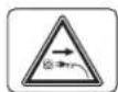
j. Mitre latch lever
k. Mitre clamp lever
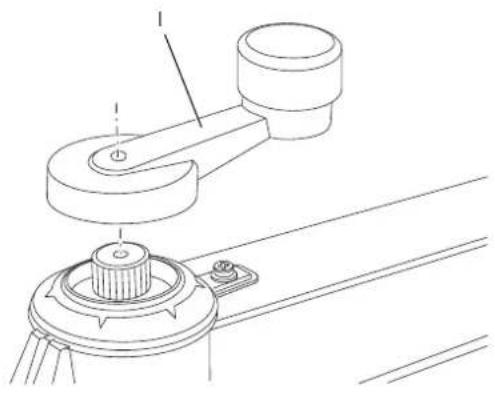
I. Height adjustment crank
m. Radial arm
n. End-cap
o. Cable
p. Dust outlet
q. Yoke assembly
r. Motor
s1. Left table strip
s2. Right table strip
t1. Left table extension
t2. Right table extension
u. Bevel scale
v. Roller head assembly
w. No-volt release switch
x. Electronic control box
INTENDED USE
The radial arm saw has been designed for professional woodworking. This high precision machine can be easily and quickly set to crosscut, bevel, mitre. For optimum safety, all major controls have both a latch and a locking device. Also refer to the quick reference chart at the end of the section. This saw is designed for use with a 300 mm diameter carbide tip blade.
DO NOT use under wet conditions or in presence of flammable liquids or gases.
The radial arm saw is a professional power tool.
DO NOT let children come into contact with the tool. Supervision is required when inexperienced operators use this tool.
Electrical Safety
The electric motor has been designed for one voltage only. Always check that the power supply corresponds to the voltage on the rating plate.
If the supply cord is damaged, it must be replaced by a specially prepared cord available through the DEWALT service organization.
Mains Plug Replacement (U.K. & Ireland Only)
SINGLE-PHASE ONLY
If a new mains plug needs to be fitted:
• Safely dispose of the old plug.
- Connect the brown lead to the live terminal in the new plug.
- Connect the blue lead to the neutral terminal.
- Connect the green/yellow lead to the earth terminal.

WARNING: Follow the fitting instructions supplied with good quality plugs. Recommended fuse: 13 A.

WARNING: This product must be earthed. Always check that the power supply corresponds to the voltage on the rating plate.
Contact a qualified electrician if a new CEE 16 A industrial plug needs to be fitted.
Using an Extension Cable
An extension cord should not be used unless absolutely necessary. Use an approved extension cable suitable for the power input of your machine (see technical data). When using a cable reel, always unwind the cable completely. The maximum cable length is 30 m.
SINGLE-PHASE MACHINES
Use an approved 3-core extension cable suitable for the power input of this machine (see technical data). The minimum conductor size is 1.5 mm ^2 .
THREE-PHASE MACHINES
Please ensure the cable is provided with CEE 16A industrial plug/ coupler 5 poles (neutral must be connected) according to IEC 60309.
Voltage Drops
Inrush currents cause short-time voltage drops. Under unfavourable power supply conditions, other equipment may be affected.
If the system impedance of the power supply is lower than 0.25 Ω, disturbances are unlikely to occur.
Sockets used for these machines shall be fused with 16 Amperes cut-out with an inert characteristic.
ASSEMBLY AND ADJUSTMENT

WARNING: To reduce the risk of injury, turn unit off and disconnect machine from power source before installing and removing accessories, before adjusting or changing set-ups or when making repairs. Be sure the switch is in the OFF position. An accidental start-up can cause injury.

WARNING: For optimum performance of your saw, it is of vital importance to follow the procedures in the paragraphs below.
Set Up
MOUNTING THE HEIGHT ADJUSTMENT CRANK (FIG. 1, 2)
- Apply the height adjustment crank (I) with the cross head screw.
NOTE: Automatic return arm may need to be moved to allow height adjustment.
- Raise the height adjustment crank high enough to provide clearance for removal of various elements under the motor.
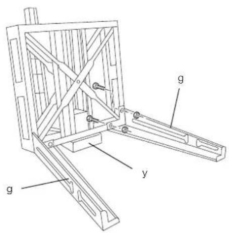
ASSEMBLING THE LEGSTAND (FIG. 1, 3, 4)
The legstand components and fasteners are packed separately.
-
Remove all parts from the package.
-
Lock the arm using the mitre clamp lever (k).
-
Tilt the machine carefully from the pallet until the rear of the column is resting on the floor.
-
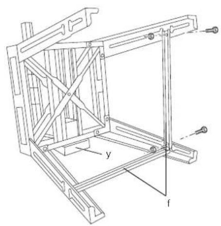
Place a piece of wood (y) under the edge of the table (fig.3).
-
Assemble the legs (g) as shown using the nuts, bolts and flat washers provided.
NOTE: Do not tighten.
-
Mount the traverse rails (f) (fig. 4).
-
Firmly tighten all fasteners.
-
Tilt the assembly to upright position.

WARNING: The machine must be level and stable at all times.
IMPORTANT: Assistance may be required to lower and raise assembly.
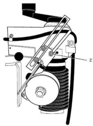
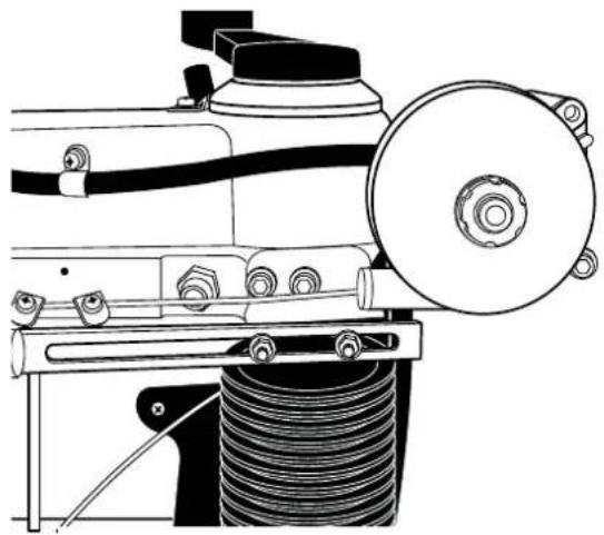
MOUNTING THE AUTOMATIC RETURN (FIG. 1, 5–10)
-
The automatic return comes partially assembled as shown in figure 5.
-
Partially unscrew automatic return retaining screw (z) with 6 mm hex key to allow for rotation of automatic return system (fig. 6).
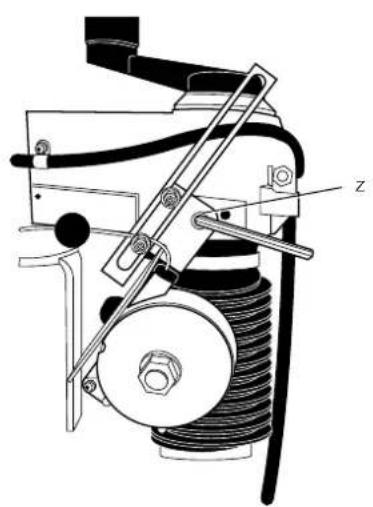
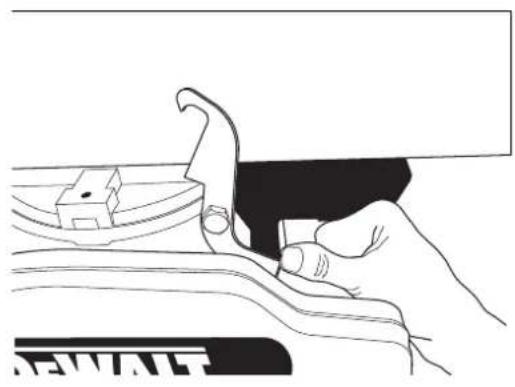
- Unlock and move the head (fig. 7).
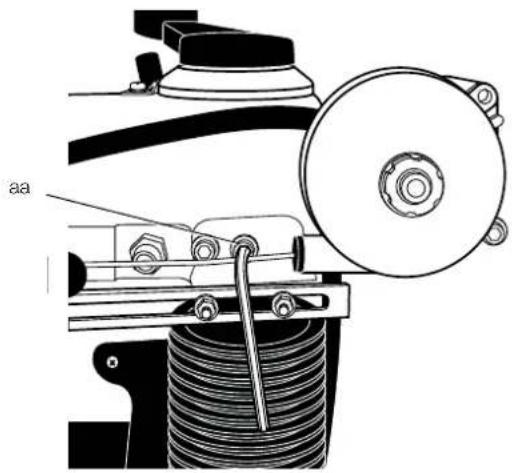
- Rotate the automatic return. Insert the second screw (aa).
NOTE: Do not tighten (fig. 8).
- Set the automatic return, checking correct alignment with the roller head (v) (fig. 1, 9).
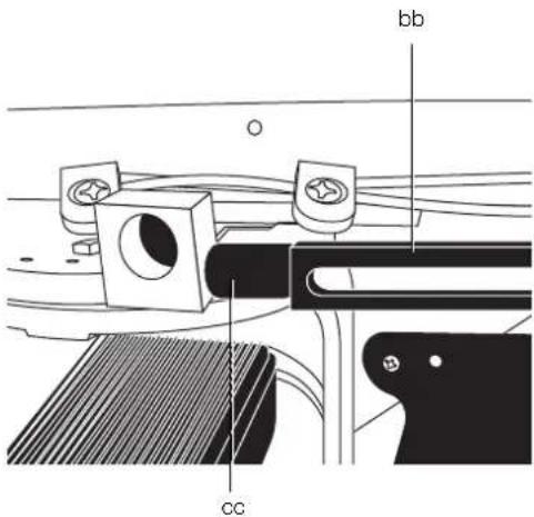
- The yoke travel stop must be adjusted so the yoke assembly bearings will not hit the rear limit of the bearing tracks. Adjust the travel stop (bb) until the rubber stop (cc) butts against the back of the riplock housing (fig. 10).

WARNING: The head must always be locked in the rest position.
- Tighten all screws.
Consult your dealer for further information on the appropriate accessories.
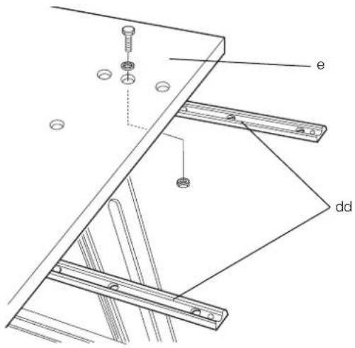
MOUNTING THE TABLE EXTENSION (FIG. 1, 11–18)
- Mount two of the table extension supports (dd) to each side of the fixed table top (e) using the M8 x 25 bolts (fig. 11).
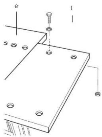
- Place a table extension (t) on the table extension support (fig. 12). Repeat with the other table extension.
- Check that the table extensions are flush with the fixed table top and securely hand tighten the bolts.

WARNING: The table extensions and the fixed table top MUST be flush.
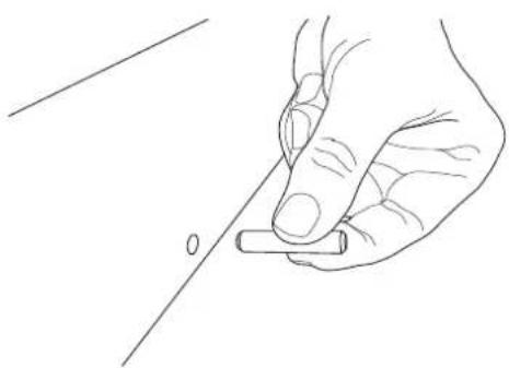
- Insert 3 dowels into the small, left fence (h1) and 3 dowels into the larger right fence (h2) (fig. 1, 13).
- Align the left fence dowels with the left side holes in the fixed table top and firmly press together (fig. 14).
- Repeat with the right fence.
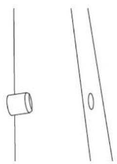
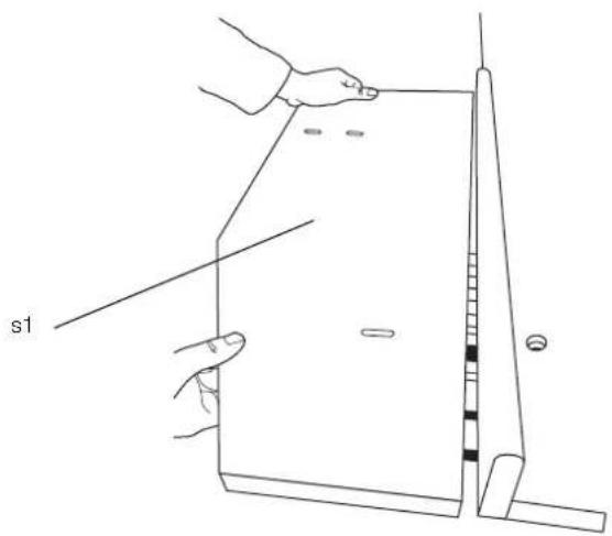
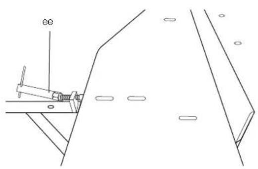
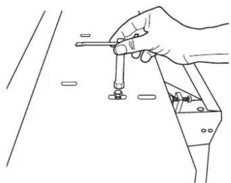
- Align the back, left table strip (s1) with the left fence dowels and firmly press together (fig. 15). Tighten the table clamp (ee) with socket wrench (fig. 16).
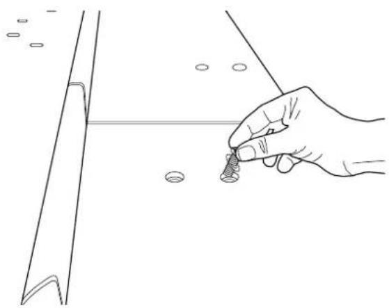
- Insert a M8 x 25 screw and D8 washer into the back, left table strip and securely tighten (fig. 17, 18).
- Repeat for back right table strip.
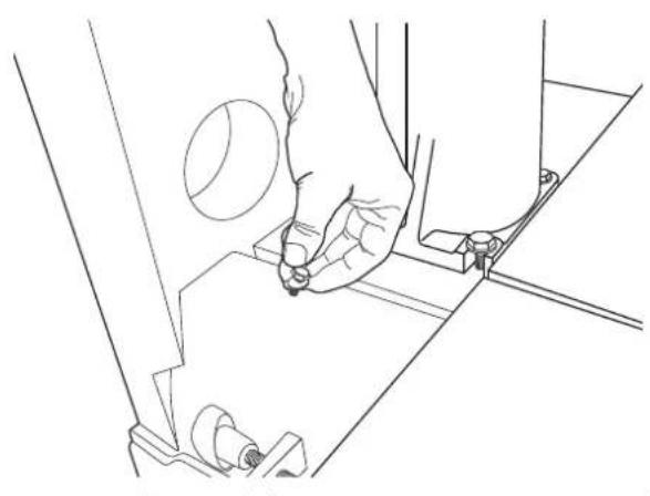
MOUNTING DUST SHROUD (FIG. 19, 20)
- Fit the dust port in position back to the column base.
- Insert 3 M8 x 16 screws and D8 washers into the dust port and base holes.
- Tighten all with 3 M8 nuts using 13 mm socket wrench and open key spanner.
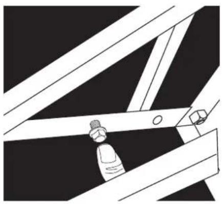
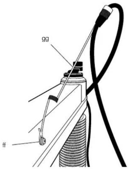
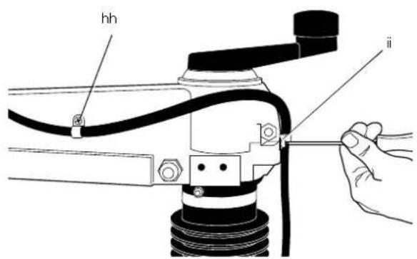
MOUNTING THE CABLE SUPPORT (FIG. 21, 22)
- Remove the cross head screw (ff).
- Mount the cable support (gg) and refit the cross head screw.
- Remove the cable clamps (hh, ii) located on the arm and reattach holding the cable in place.

WARNING: Allow for the arm movement in horizontal and vertical direction.
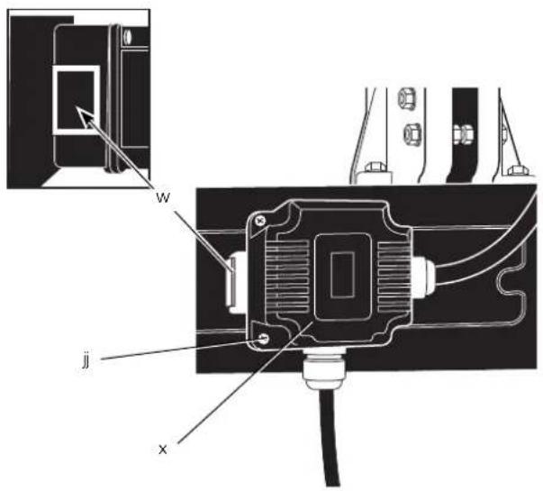
MOUNTING THE ELECTRONIC CONTROL BOX (FIG. 23)
Wired into the mains cable is the electronic control box (x) containing the no-volt release switch (w), the braking device and the motor overload protector with automatic reset.
- Remove the nuts from the screws (jj) protruding out of the rear of the box (x).
- Hold the box against the rear of the table frame to the left of the column base and insert the screws into the corresponding holes.
- Replace the nuts onto the end of the screws and tighten them.
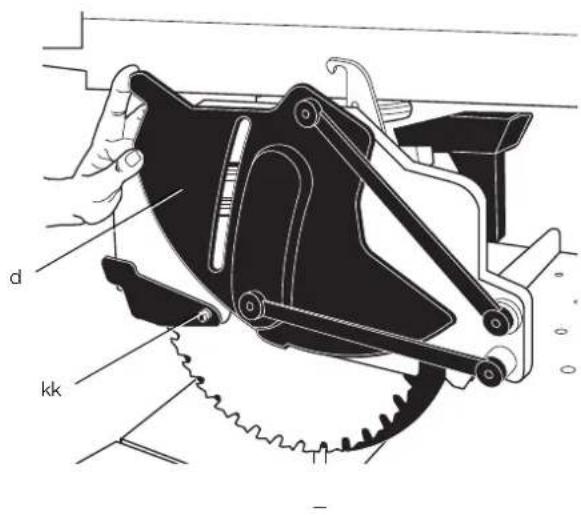
MOUNTING THE SAW BLADE (FIG. 24-33)
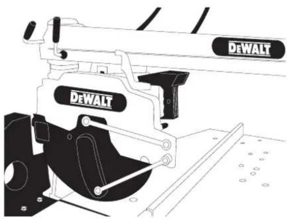
- Ensure that the arm position is at 0^ and raise the arm (m) to the upper position (fig. 24).
-
Loosen the guard screw (kk) and lift the guard (d) out of the way (fig. 25).
-
Using the 6 mm hex key inserted into the motor spindle and the 13 mm spanner key on the blade screw (fig. 26), turn the spanner key clockwise to remove the blade screw (II) and external flange (mm).
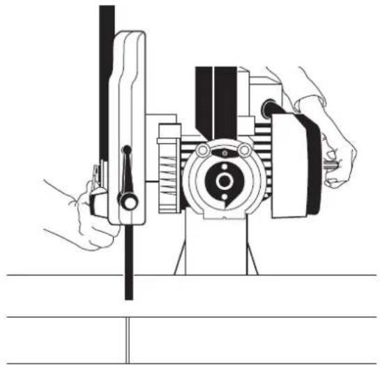
- Remove the blade from the spindle and fit the blade in the slot (nn) of the table fence. The teeth blade MUST NOT come into contact the spindle (fig. 27, 28).
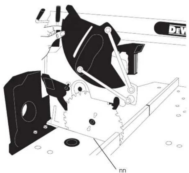
- Unlock the head and move the head forward until the blade can be removed from the slot (nn). Place the new blade (oo) into the slot (nn) and move the head slowly into the rest (locked) position assuring that the teeth of the blade does not come into contact with the spindle (fig. 29–31).
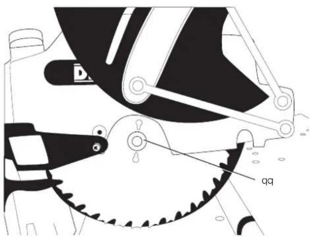
- Place the new blade onto the internal flange (qq). Place the external flange on the spindle. Using a 6 mm hex key in the motor spindle and the 13 mm spanner key on the blade screw, tighten the blade screw and external flange (fig. 32).
- Lower the guard so the guard slot is aligned with the guard screw and tighten the screw (fig. 33).
- The head is ready for cutting.

WARNING: The teeth of a new blade are very sharp and can be dangerous.

WARNING: The direction of rotation is indicated by the arrow on the motor.

WARNING: Make sure that the washer of the arbour nut is against the outer flange.
CHECKING THAT THE ARM IS PARALLEL TO THE TABLE TOP (FIG. 1, 34)
- Lower the blade (oo) until it only just touches the fixed table top (e).
- Release the mitre latch lever (j) and the mitre clamp lever (k).
- Extend the blade forward past the fence then swing arm so that the blade skims the table top across its width.
- Repeat this procedure with the blade in rear position and adjust the rear bolt if required.
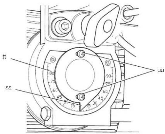
CHECKING THAT THE BLADE IS PERPENDICULAR TO THE TABLE TOP (FIG. 1, 35–37)
- Bring the arm (m) back to central position.
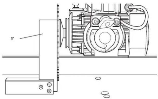
- Place a steel square (rr) against the blade body (fig. 35).
- If adjustment is required, proceed as follows:
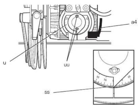
a. Remove the bevel pointer disk (tt) by loosening the two screws (uu) (fig. 36).
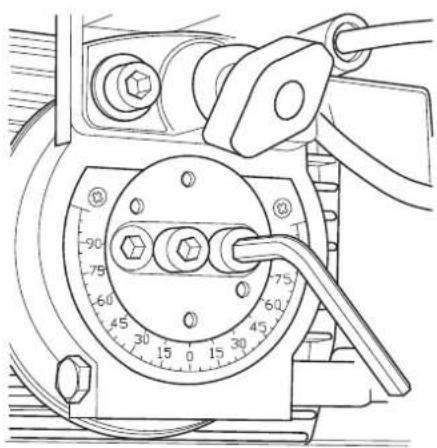
b. Loosen all three hex screws that will be exposed in this way (fig. 37).
c. Place a hex key in the motor arbour and tap until the blade is flat against the square.
- Firmly tighten all fasteners.

WARNING: It is particularly important to tighten the central hex screw.
- Replace the bevel pointer disk (tt) aligning the pointer (ss) at 0^ .
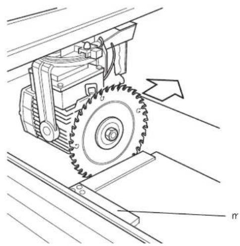
CHECKING THAT THE CROSSCUT TRAVEL IS PERPENDICULAR TO THE FENCE (FIG. 38–42)
- Extend the blade in front of the fence (fig. 38).
- Place a square (rr) on a piece of board and against the fence and just touching the blade as shown.
- Pull the blade towards you to check that the blade traverses parallel to the square.
- If adjustment is required, proceed as follows:
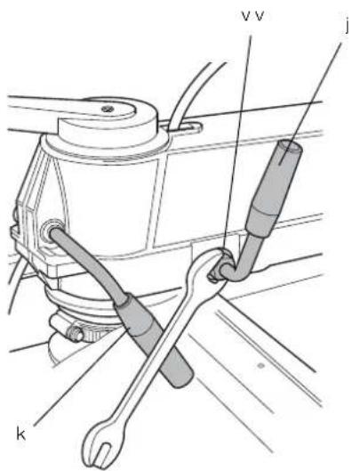
a. With the mitre latch lever (j) engaged in 0^ position, release the mitre clamp lever (k) as shown in figure 39.
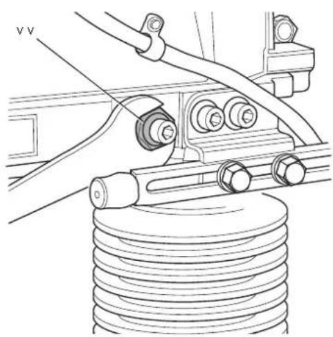
b. Loosen the locknuts (v v) on each side of the arm (m), shown in figure 40.
- To adjust the arm (m) to the left, loosen the stud (ww) on the right-hand side of the arm and tighten the opposite stud (fig. 41).
- To adjust the arm (m) to the right, loosen the stud (ww) on the left-hand side of the arm and tighten the opposite stud.
- Proceed in small steps and check the adjustment after each step with the levers (j, k) engaged.

G: Do not overtighten the studs.
-
Tighten the locknuts (v v).
-
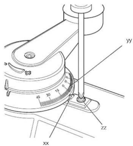
Adjust the pointer (xx) on the mitre scale (yy) so that it registers 0^ (fig. 42).
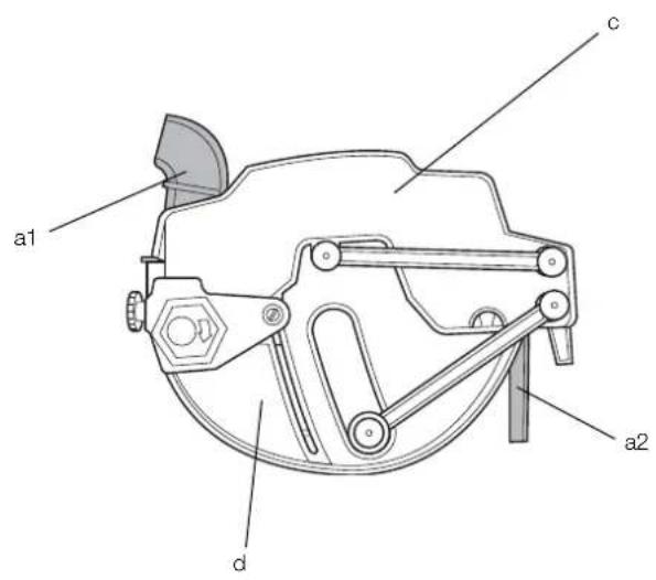
Blade Guard Assembly (fi g. 43)
The blade guard is a multifunctional assembly which offers the following safety features:
- Front guard (c) and spring-held rear guard (d) for full blade protection.
– Dust extraction adapter (a1).
- Adjustable finger guard (a2) for use when cross-cutting.
BEVEL SCALE (FIG. 44)
Check that the bevel scale (u) reads 0^ when positioned for a vertical cut.
If required, loosen the screws (uu) and adjust the pointer to 0°.
MITRE SCALE (FIG. 42)
Check that the mitre scale (yy) reads 0^ when positioned for a vertical cut.
Adjust the pointer (xx) to register 0^ using the screw (zz).
The arm has preset positions at 45^ left and right and at 0^ .
OPERATION
Instructions for Use

• Always observe the safety instructions and applicable regulations.
• Ensure the material to be sawn is firmly secured in place.
- Apply only a gentle pressure to the tool and do not exert side pressure on the saw blade.
- Avoid overloading.

• Install the appropriate saw blade. Do not use excessively worn blades. The maximum rotation speed of the tool must not exceed that of the saw blade.
- Do not attempt to cut excessively small pieces.
- Allow the blade to cut freely. Do not force.
- Allow the motor to reach full speed before cutting.
- Make sure all locking knobs and clamp handles are tight.
- Never run the machine without the guards in place.
- Never lift the machine by the table top.
• Always check that there is a suitable slot in the table top.
• Always refer to figure L to check the fence position and type.
The attention of UK users is drawn to the “woodworking machines regulations 1974” and any subsequent amendments.
SWITCHING ON AND OFF (FIG. 1)
The on/off switch of your radial arm saw offers multiple advantages:
- No-volt release function: should the power be shut off for some reason, the switch has to be deliberately reactivated.
- Motor overload protection device: in case of motor overload, the power supply to the motor will be cut off. If this happens, let the motor cool for 10 minutes and then press the reset button.
- Braking system: after switching off, the braking system will stop the saw blade within 10 seconds.
- The switch has hold-to-run functions only.
To switch the machine on, press the green actuator (a) in the handle (b). When the actuator is released the machine stops automatically.
MAKING A TRIAL CUT (FIG. 1)
-
With the mitre latch lever (j) engaged, lock the mitre clamp lever (k) so that the blade is positioned for a straight 0^ cross-cut.
-
Lower the arm until the blade almost touches the table top.
- Place the workpiece against the front of the fence.
- Switch on and lower the arm to allow the blade to cut a shallow groove in the table surface.
- Pull the blade towards you so that it cuts a vertical slot in the wooden fence and through the workpiece.
- Return the blade back to rest position and switch off.
- Check that the cut is a true 90^ in all planes and adjust if required.
Basic Saw Cuts (fi g. 45–53)

WARNING: The teeth of a new blade are very sharp and can be dangerous.
CROSS-CUTTING (FIG. 45)
- Set the radial arm at right angles to the fence.
- Engage the mitre latch lever (j) in 0° position and tighten the mitre clamp lever (k).
- Lower the blade.
- Adjust the finger guard (a2) so that it just clears the workpiece.
- If there is no slot in the table top, cut one as described above.
- Hold the workpiece against the fence, keeping your fingers well away from the path of the blade.
- Switch on and slowly pull the blade through the fence and the workpiece.
- Return the blade to rest position and switch off.
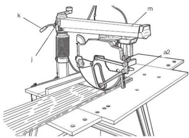
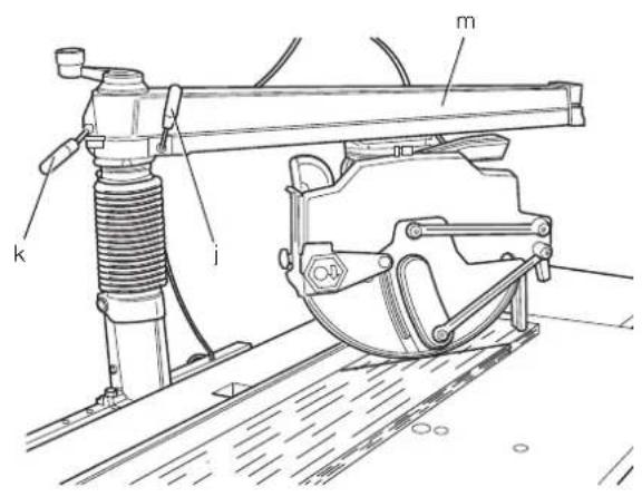
MITRE CUTS (FIG. 46, 47)
- Release the mitre latch lever (j) and the mitre clamp lever (k).
- Swing the arm to the required angle on the mitre scale.
-
For 45^ left or right, engage the mitre latch lever (j) and lock with the mitre clamp lever (k).
-
For intermediate angles, use the mitre clamp lever only.
- Proceed as for cross-cutting.
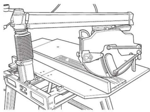
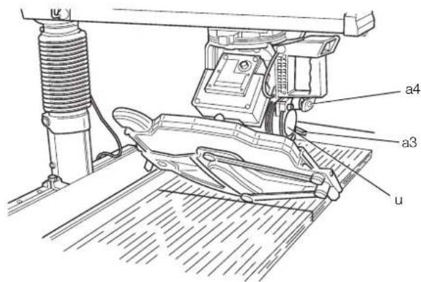
BEVEL CUTS (FIG. 45, 48)
- Set the arm as for a 0^ cross-cut.
- Raise the blade well above the table surface.
- Release the bevel clamp lever (a3) and pull out the bevel latch (a4).
- Tilt the motor to the required angle on the bevel scale (u).
- For 45^ right, engage the bevel latch (a4) and lock with the bevel clamp lever (a3).
- For intermediate angles, use the bevel clamp lever only.
- Proceed as for a vertical cross-cut.
COMPOUND MITRE (FIG. 47)
This cut is a combination of a mitre and a bevel cut.
- Set the required bevel angle.
- Swing the arm to the required mitre position.
- Proceed as for mitre cuts.
MAINTENANCE
Your DEWALT power tool has been designed to operate over a long period of time with a minimum of maintenance. Continuous satisfactory operation depends upon proper tool care and regular cleaning.
NOTE: No service is needed on mechanical brake.
IMPORTANT: Replace the fixed table top and fence when worn.

WARNING: To reduce the risk of injury, turn unit off and disconnect machine from power source before installing and removing accessories, before adjusting or changing set-ups or when making repairs. Be sure the switch is in the OFF position. An accidental start-up can cause injury.

WARNING: if the saw blade is worn replace it with a new or re-sharpened blade.
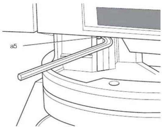
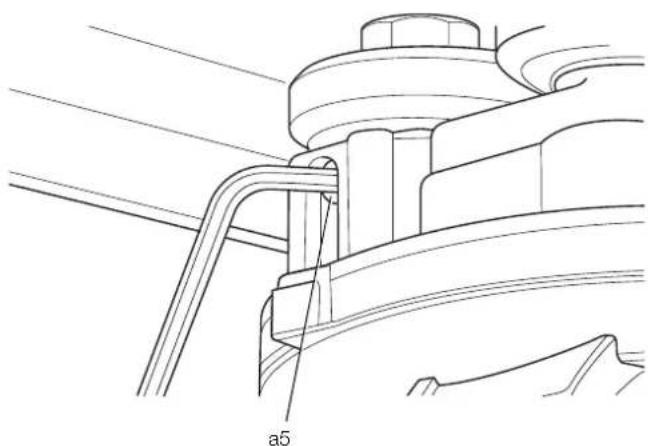
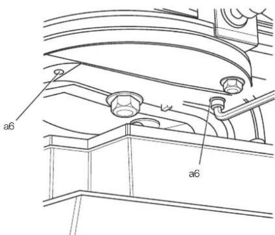
Adjusting the Roller Head Bearings Arm Tracks (fi g. 49–52)
If lateral movement is occurring in the roller head assembly, the bearings need adjustment.
- Pull the yoke assembly forward to the end of the arm tracks and keep in position (fig. 49).
- Loosen the locking screws (a5) (fig. 50, 51).
- Using an hex key, slightly rotate the bearings (a6) until lateral movement has been neutralised (fig. 52).
- Retighten the locking screws (a5) ensuring that the head automatically goes into the rest position.

Lubrication
Your power tool requires no additional lubrication.

Cleaning
Before use, carefully check the upper blade guard, movable lower blade guard as well as the dust extraction tube to determine that it will operate properly. Ensure that chips, dust or workpiece particle cannot lead to blockage of one of the functions.
In case of workpiece fragments jammed between saw blade and guards disconnect the machine from the power supply and follow the instructions given in section Mounting the Saw Blade. Remove the jammed parts and reassembling the saw blade.

WARNING: Blow dirt and dust out of the main housing with dry air as often as dirt is seen collecting in and around the air vents. Wear approved eye protection and approved dust mask when performing this procedure.

WARNING: Never use solvents or other harsh chemicals for cleaning the non-metallic parts of the tool. These chemicals may weaken the materials used in these parts. Use a cloth dampened only with water and mild soap. Never let any liquid get inside the tool; never immerse any part of the tool into a liquid.

WARNING: To reduce the risk of injury, regularly clean the table top.

WARNING: To reduce the risk of injury, regularly clean the dust collection system.

Dust Extraction

WARNING: Always connect a dust extraction device designed in accordance with relevant regulation regarding dust emission. The air velocity of external connected system shall be 20m/s +/-2m/s. Velocity to be measured in the connection tube at the point of connection, with the tool connected but not running.
Transporting
To transport the machine be sure the saw head is safely locked. Please be aware the table is not suitable to lift the machine up. Always use a fork-lift for transporting. For safe lifting set the fork under the lower cross-bar of the leg-stand.
Optional Accessories

WARNING: Since accessories, other than those offered by DEWALT, have not been tested with this product, use of such accessories with this tool could be hazardous. To reduce the risk of injury, only DEWALT, recommended accessories should be used with this product.
Consult your dealer for further information on the appropriate accessories.
Recommended saw blade DW721 / DW722 - DT4303
Protecting the Environment

Separate collection. This product must not be disposed of with normal household waste.
Should you find one day that your DEWALT product needs replacement, or if it is of no further use to you, do not dispose of it with household waste. Make this product available for separate collection.

Separate collection of used products and packaging allows materials to be recycled and used again. Re-use of recycled materials helps prevent environmental pollution and reduces the demand for raw materials.
Local regulations may provide for separate collection of electrical products from the household, at municipal waste sites or by the retailer when you purchase a new product.
DEWALT provides a facility for the collection and recycling of DEWALT products once they have reached the end of their working life. To take advantage of this service please return your product to any authorised repair agent who will collect them on our behalf.
You can check the location of your nearest authorised repair agent by contacting your local DEWALT office at the address indicated in this manual. Alternatively, a list of authorised DEWALT repair agents and full details of our after-sales service and contacts are available on the Internet at: www.2helpU.com.
GUARANTEE
DEWALT is confident of the quality of its products and offers an outstanding guarantee for professional users of the product. This guarantee statement is in addition to and in no way prejudices your contractual rights as a professional user or your statutory rights as a private non-professional user. The guarantee is valid within the territories of the Member States of the European Union and the European Free Trade Area.
• 30 DAY NO RISK SATISFACTION GUARANTEE •
If you are not completely satisfied with the performance of your DEWALT tool, simply return it within 30 days, complete with all original components, as purchased, to the point of purchase, for a full refund or exchange. The product must have been subject to fair wear and tear and proof of purchase must be produced.
• ONE YEAR FREE SERVICE CONTRACT •
If you need maintenance or service for your DEWALT tool, in the 12 months following purchase, you are entitled to one service free of charge. It will be undertaken free of charge at an authorised DEWALT repair agent. Proof of purchase must be produced. Includes labour. Excludes accessories and spare parts unless failed under warranty.
• ONE YEAR FULL WARRANTY •
If your DEWALT product becomes defective due to faulty materials or workmanship within 12 months from the date of purchase, DEWALT guarantees to replace all defective parts free of charge or – at our discretion – replace the unit free of charge provided that:
• The product has not been misused;
- The product has been subject to fair wear and tear;
- Repairs have not been attempted by unauthorised persons;
• Proof of purchase is produced.
- The product is returned complete with all original components
If you wish to make a claim, contact your seller or check the location of your nearest authorised DEWALT repair agent in the DEWALT catalogue or contact your DEWALT office at the address indicated in this manual. A list of authorised DEWALT repair agents and full details of our after-sales service is available on the Internet at: www.2helpU.com
QUICK REFERENCE CHART
text_image
height adjustment crank mitre latch lever mitre clamp lever bevel latch bevel clamp leverINGLETADORA
DW721KN, DW722KN
¡Enhorabuena!
MACHINES MONOPHASÉES
MISE EN MARCHE ET ARRÊT (FIG. 1)
COUPE D'ESSAI (FIG. 1)
SQUADRATRICE RADIALE DW721KN, DW722KN
Congratulazioni!
Recommended saw blade DW721 / DW722 - DT4303
Rispetto ambientale

ZAAG MET ZWENKBARE ARM DW721KN, DW722KN
Vice President Engineering and Product Development DEWALT, Richard-Klinger-Straße 11,
DE STOF BESCHERMKAP MONTEREN (FIG. 19, 20)
AAN EN UIT SCHAKELEN (FIG. 1)
AFSCHUINSNEDEN (FIG. 45, 48)
RADIALARMSAG DW721KN, DW722KN
Gratulerer!
Check that the mitre scale (yy) reads 0^ when positioned for a vertical cut.
SERRA DE BRAÇO RADIAL DW721KN, DW722KN
Parabéns!
- Retire as chaves de ajuste.