MFSBM1-B1 - Speaker stands SANUS - Free user manual and instructions
Find the device manual for free MFSBM1-B1 SANUS in PDF.

User questions about MFSBM1-B1 SANUS
0 question about this device. Answer the ones you know or ask your own.
Ask a new question about this device
Download the instructions for your Speaker stands in PDF format for free! Find your manual MFSBM1-B1 - SANUS and take your electronic device back in hand. On this page are published all the documents necessary for the use of your device. MFSBM1-B1 by SANUS.
USER MANUAL MFSBM1-B1 SANUS
text_image
SANUS® Arrived in EnglandMFSBM1-B1
UNIVERSAL SOUNDBAR MOUNT
Compatible with
Amazon Fire TV 4-series
and Fire TV Omni Series
INSTRUCTION MANUAL
natural_image
Line drawing of two articulated arms mounted on a stand, no text or symbols presentWE'RE HERE TO HELP
natural_image
Black-and-white photo of two men in conversation, one gesturing with hand (no visible text or symbols)Our install experts are standing by to help.

Call us at:
US: +1 (800) 359-5520
EMEA: +31 (0) 495 580 851
UK: +44 (0) 800 056 2853
IMPORTANT SAFETY INSTRUCTIONS
— SAVE THESE INSTRUCTIONS — PLEASE READ ENTIRE MANUAL PRIOR TO USE
Before getting started, let's make sure this mount is perfect for you!
The COMBINED weight of this soundbar mount, your soundbar, any accessories and your TV, MUST BE LOWER than the maximum weight rating of your TV mount/stand (See PAGE 4).
▶ Refer to the documentation that came with your sound bar, your TV and your TV wall mount for additional guidance.
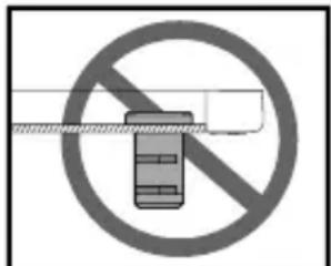
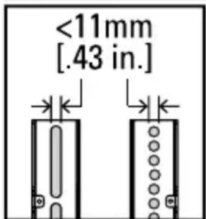
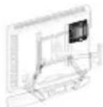
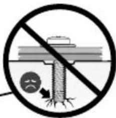
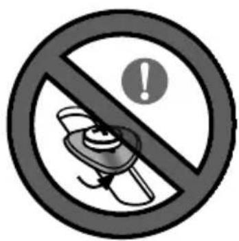
▶ You CANNOT use this product if your TV mount's interface bracket: includes built-in/integrated spacers (See Figure 1), or, the mounting holes/slots are greater than 11mm [.43 in.] (See Figure 2).
text_image
Prohibition sign indicating no smoking or anti-smoking, featuring a crossed-out device symbolFigure 1
text_image
<11mm [.43 in.]Figure 2
WARNING:
This soundbar mount is only designed for use with TV wall mounts that meet third party safety certifications (UL Certified).
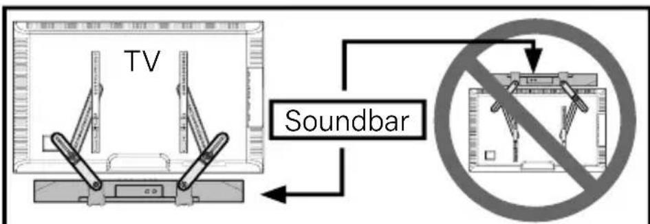
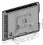
This soundbar mount is ONLY designed to mount BELOW the television (See Figure 3).
This soundbar mount is designed to be installed and utilized only as specified in this manual. The manufacturer is not responsible for improper assembly, use, or handling of this product.
■ Failure to follow these instructions could result in an unstable situation that may result in property damage or personal injury.
text_image
TV SoundbarFigure 3
If you have any questions, please contact customer service.
US: 800-359-5520
EMEA: +31 (0) 495 580 852
UK: 0800 056 2853
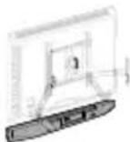
Weight Restrictions
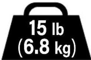
Weight Limit for this Soundbar Mount
text_image
15 lb (6.8 kg)DO NOT EXCEED
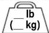
TOTAL Weight Limit for Your TV Mount/Stand
CAUTION:
Avoid potential personal injuries and property damage!
The COMBINED weight of this soundbar mount, your soundbar, any accessories and your TV, must be LOWER than the maximum weight rating of your TV mount/stand.
See your TV mount's manual for maximum weight allowed.
Soundbar Mount
Your Soundbar Y (See Manufacturer specifications for your soundbar's weight)
TV ANY Other Accessories

(See Manufacturer specifications for your TV's weight)


Total Maximum weight for Your TV Mount/stand

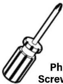
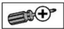
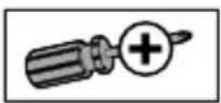
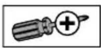
Tools Needed (not included)
text_image
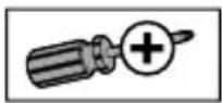
Phil ScrewPhillips Screwdriver
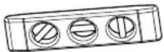
Level
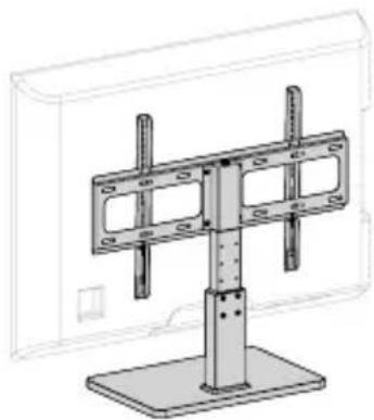
3rd Party Certified TV stand or Wall Mount\*
natural_image
Technical line drawing of a mechanical support structure with mounting base (no text or symbols)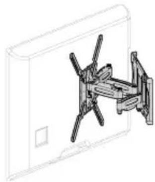
natural_image
Technical line drawing of a mechanical assembly or mounting bracket (no text or symbols)* The TV mount styles illustrated will vary, though the install procedures are the same.
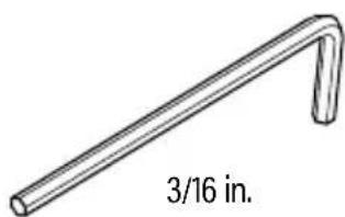
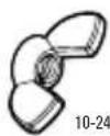
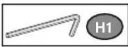
INCLUDED
text_image
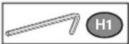
3/16 in.Hex Key

For Amazon Fire TV Soundbars
Included in your Amazon Fire TV Soundbar Kit
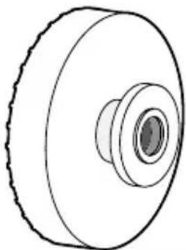
natural_image
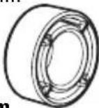
Technical line drawing of a pulley or wheel component (no text or symbols)Mounting Rings

qty.2
Supplied Parts and Hardware
WARNING: This product contains small items that could be a choking hazard if swallowed. Before starting assembly, verify all parts are included and undamaged. If any parts are missing or damaged, do not return the damaged item to your dealer; contact Customer Service. Never use damaged parts! NOTE: Not all hardware included will be used.
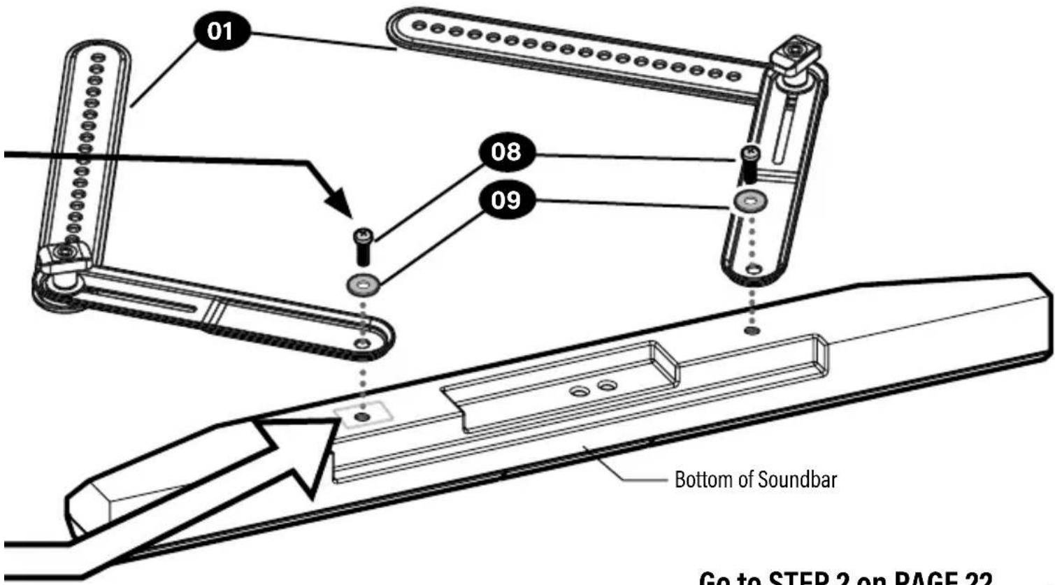
Parts and Hardware for STEP 1
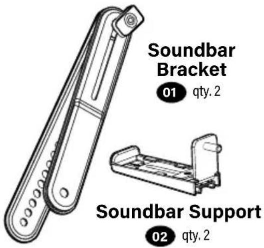
text_image
Soundbar Bracket 01 qty. 2 Soundbar Support 02 qty. 2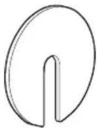
natural_image
Simple line drawing of a circular object with a vertical slot, resembling a stylized letter or symbol (no text or symbols present)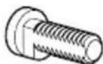
1/4-20
Keyhole Screw
04 qty.2
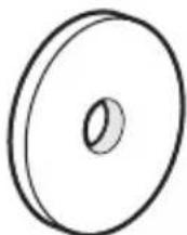
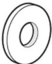
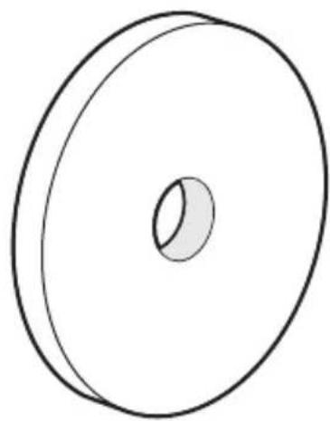
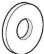
Fender Washer
03 qty.2
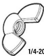
Keyhole Nut
05 qty.2
for Amazon Fire TV soundbars
Fire TV Screw
06 qty.2
Keyhole Nut
07 qty.2
Parts and Hardware for STEP 1 Part for STEP
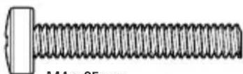
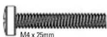
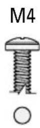
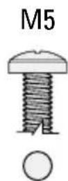
Soundbar Screws
qty. 2 each
08
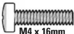
M4
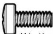
M4 x 10mm
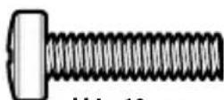
M4 x 16mm
M5
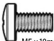
M5 x 10mm
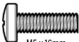
M5 x 16mm
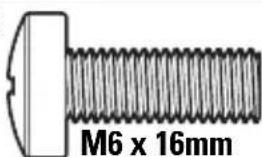
M6
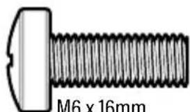
text_image
M6 x 16mmM6 x 16mm
1/4-20
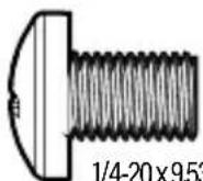
1/4-20×9.53 mm (3/8")
8
Soundbar Washers
qty. 2 of 6 each
09
M4 / M5
Washer
M6 / M8
Washer
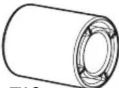
Mount Spacer
10 qty.2
natural_image
Simple line drawing of a circular mechanical part with a central hole (no text or symbols)Parts and Hardware for STEP 3
TV Interface Screws 11 qty. 4 each
M4
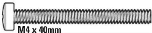
text_image
M4 x 40mmM6
text_image
M6 x 16mm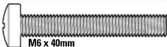
text_image
M6 x 40mmM8
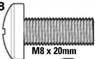
text_image
3 M8 x 20mm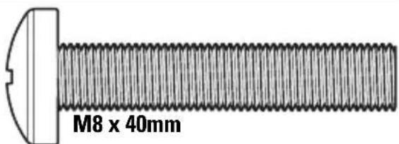
text_image
M8 x 40mm
text_image
M8 x 55mmWashers Spacers
12 qty. 4 of 6 each
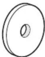
M4 / M5 Washer
M6 / M8
Washer
pacers
13
qty. 4 each
natural_image
Simple line drawing of a cylindrical mechanical part with a flanged end (no text or symbols)TV Spacer 22mm
5mm
2.5mm
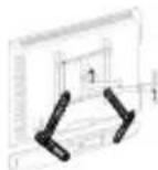
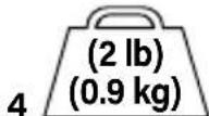
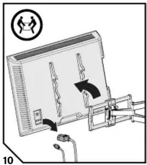
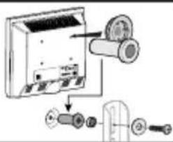
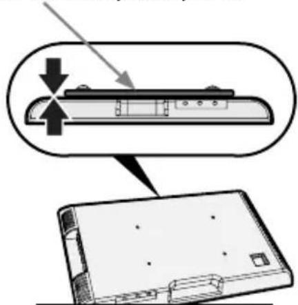
Prep Your TV (if mounted on a wall or stand)
CAUTION: Follow your TV mount's instruction manual to safely remove your TV and TV bracket(s).
text_image
Diagram showing a device with labeled components and directional arrows, including a circled icon indicating 'Person holding a box'.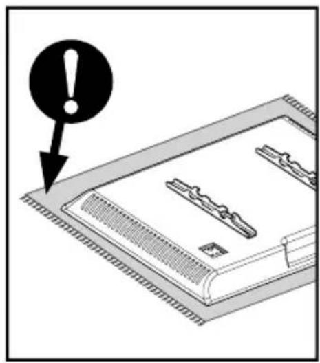
text_image
Warning symbol with exclamation mark pointing to a document or folder, indicating alert or warning.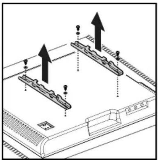
natural_image
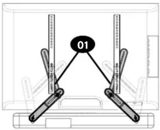
Technical diagram of a mechanical assembly with two mounted components and upward arrows indicating motion (no text or symbols)STEP 1
Install Brackets on Your Soundbar
Amazon Fire TV Soundbars, use install option A.
| OPTION A: | Amazon Fire TV Soundbar | PAGE 12 |
For all other soundbars, look at the mounting holes on the back or bottom of your soundbar to determine your install option B, C or D.
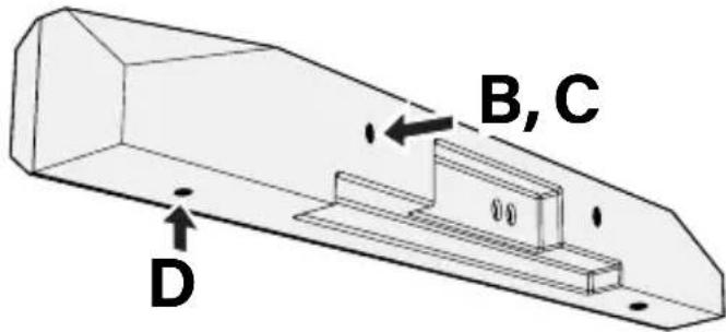
text_image
B, C D| OPTION B: | Back-Mount Holes with THREADED INSERTS  | PAGE 16 |
| OPTION C: | Back-Mount Holes with KEY HOLE SLOTS  | PAGE 18 |
| OPTION D: | BOTTOM-MOUNT HOLES with Threaded Inserts  | PAGE 20 |
OPTION

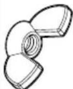
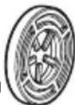
Amazon Fire TV Soundbar
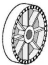
Mounting Rings

qty. 2
Fire TV Screw
06 qty.2
Keyhole Nut
07 qty.2
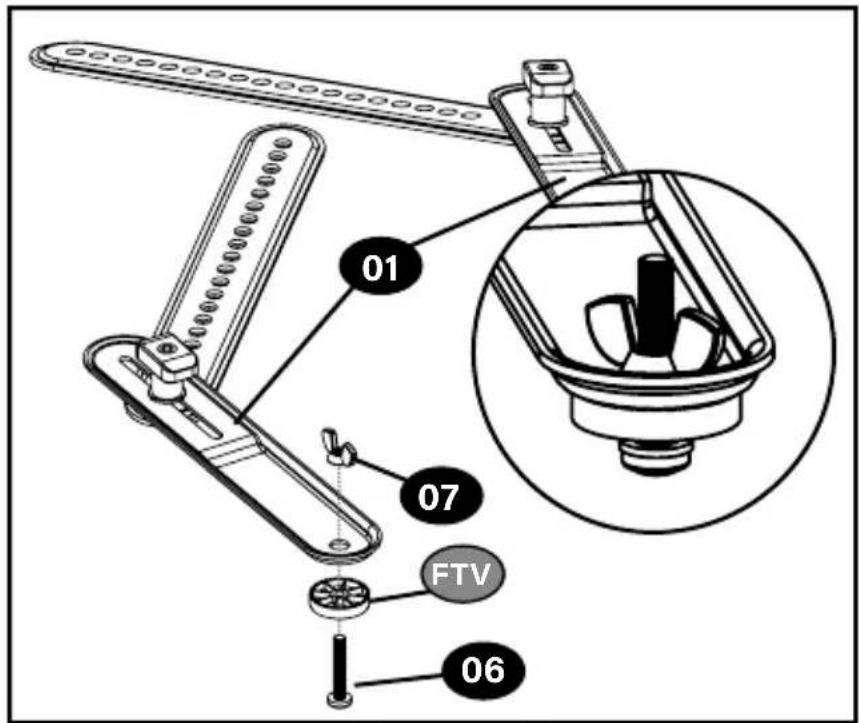
text_image
01 07 FTV 06Align your soundbar at the bottom of your TV - leaving enough room to reach the buttons. Adjust Soundbar brackets 01 to align with your TV bottom mounting holes and your soundbar mounting holes, then tighten knobs T.
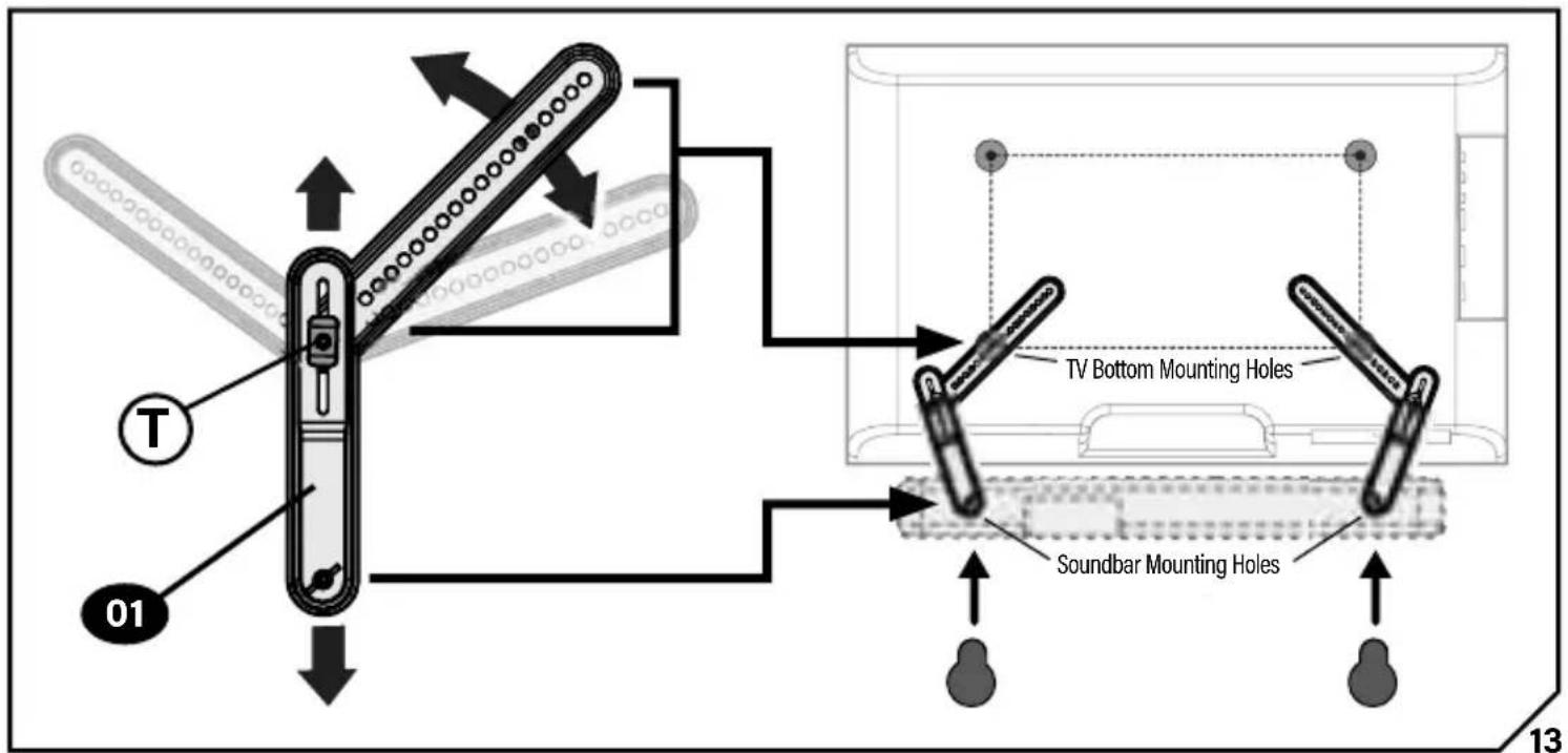
text_image
TV Bottom Mounting Holes Soundbar Mounting Holes 01 T 13
NOTE: Try to position the soundbar brackets 01 as vertically as possible.

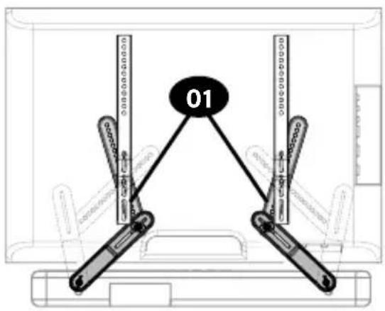
text_image
01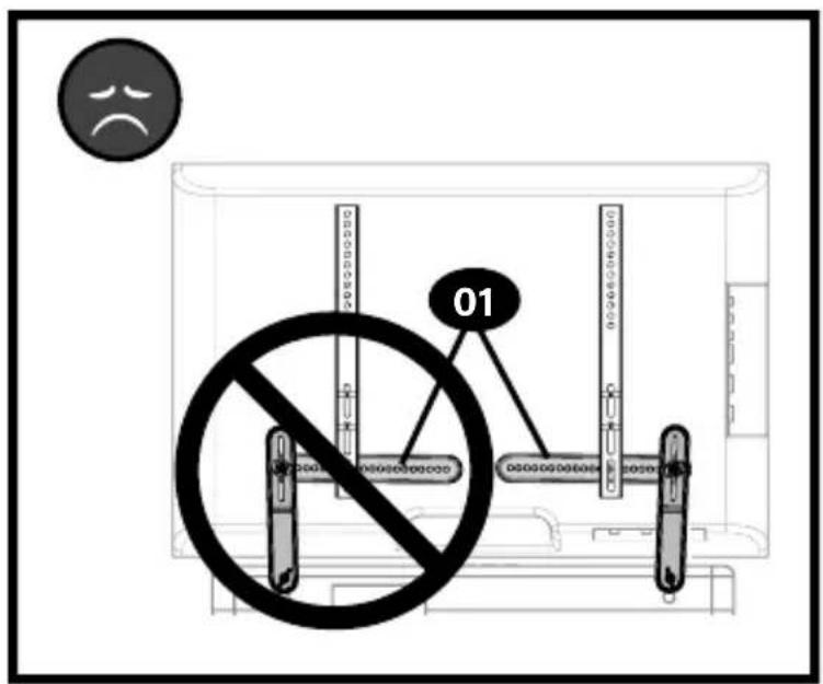
text_image
01
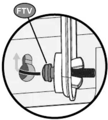
IMPORTANT: DO NOT install your soundbar onto the mounting rings FTV until AFTER you hang your TV.
NOTE: Your Fire TV soundbar does not lock onto the mounting rings FTV - be careful when adjusting your TV or soundbar.
Go to STEP 3 on PAGE 26
text_image
FTVOPTION
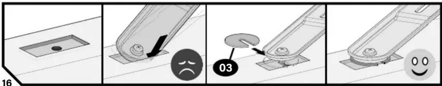
B:
Back-Mount Holes with THREADED INSERTS
Only one size screw 08 fits your Soundbar (M4, M5, M6 or 1/4-20).

IMPORTANT:
If soundbar brackets 01 do not rest flat on your soundbar surface, use fender washers 03 as shown.
text_image
01 08 09 Bottom of Soundbar Go to STEP 2 on PAGE 22Go to STEP 2 on PAGE 22
OPTION

Back-Mount Holes with KEY HOLE SLOTS
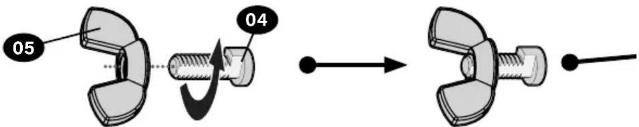
text_image
05 04IMPORTANT:
If soundbar brackets 01 do not rest flat on your soundbar surface, use fender washer 03 as shown.
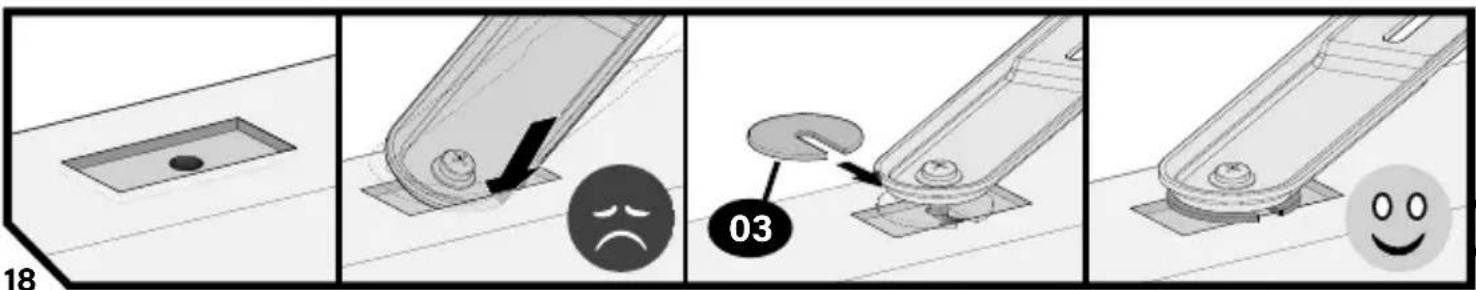
text_image
Technical diagram illustrating a mechanical assembly process with labeled components and visual indicators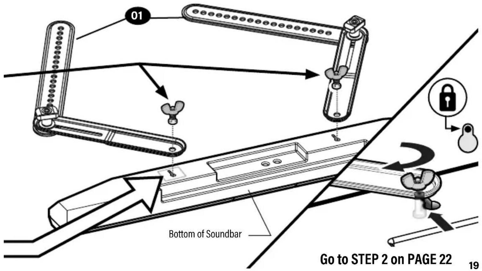
text_image
01 Bottom of Soundbar Go to STEP 2 on PAGE 22 19
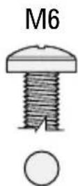
Bottom-Mount Holes with Threaded Inserts
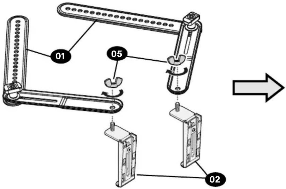
text_image
01 05 02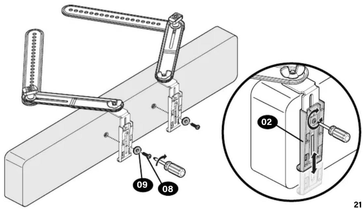
text_image
Technical diagram showing mechanical assembly with labeled parts and a magnified inset of a device component labeled 02 and 08.STEP 2 Position your Soundbar
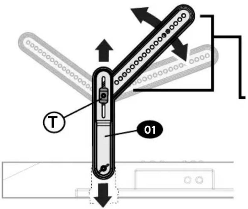
Adjust Soundbar brackets 01 to align with your TV bottom mounting holes, then tighten knobs Ⓣ.
text_image
T 01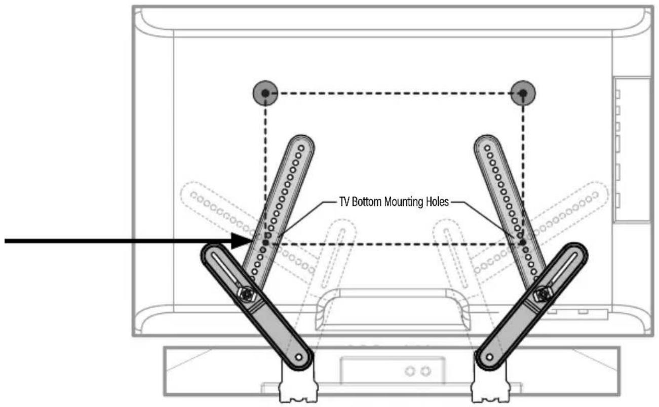
text_image
TV Bottom Mounting Holes
NOTE: Try to position the soundbar brackets 01 as vertically as possible.

text_image
01
text_image
01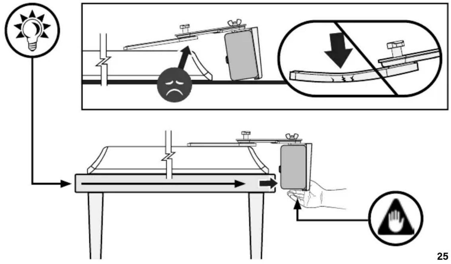
text_image
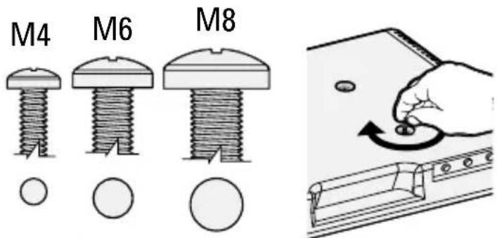
Diagram illustrating a lighting and safety procedure with labeled components and directional arrowsSTEP 3 Install the Soundbar Brackets to Your TV
3.1 TV Interface Screw Diameter
Only one screw size 11 fits your TV (M4, M6 or M8).
text_image
M4 M6 M8
NOTE: If your TV
included inset spacers or adapters, use them UNDER the mount hardware.
text_image
Diagram showing a device with labeled components and directional arrows indicating assembly or connection.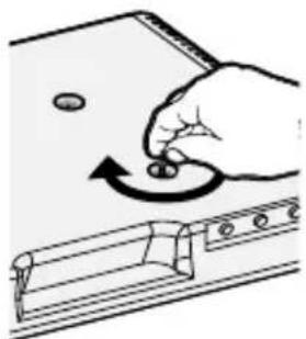
natural_image
Illustration of a hand turning a knob on a device panel (no text or symbols)3.2 TV Interface Screw Length
CAUTION:
Verify adequate thread engagement with screw 11 along with:
■ Washer 12
- Spacer 13 (if used)
■ Sound bar bracket 01
- Your TV mount's bracket
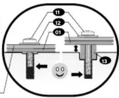
text_image
11 12 01 13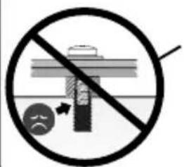
text_image
Prohibition sign with crossed-out diagram and circular icon showing a person holding a tool, indicating no protection or hazard.Too short will not hold your TV.
Too long will- damage your TV.
text_image
Prohibition sign with crossed-out screw and sad face, indicating no protection or damage
NO SPACERS 13
For Flat Back TV
[TV brackets lay flat on your TV]
natural_image
Diagram showing a device with a lock and a separate panel, no text or symbols presentGO TO PAGE 28 G

SPACERS 13 NEEDED
For Flat Back TV
with Extra Space Needed
[for deep inset holes or cable interference]
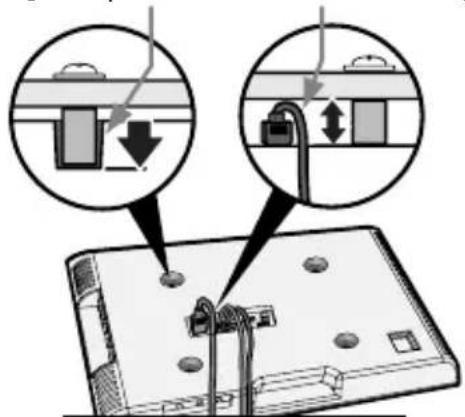
text_image
Diagram showing installation of a device with labeled components and directional arrows indicating assembly or connection steps.GE 29 GO TO PAGE 29
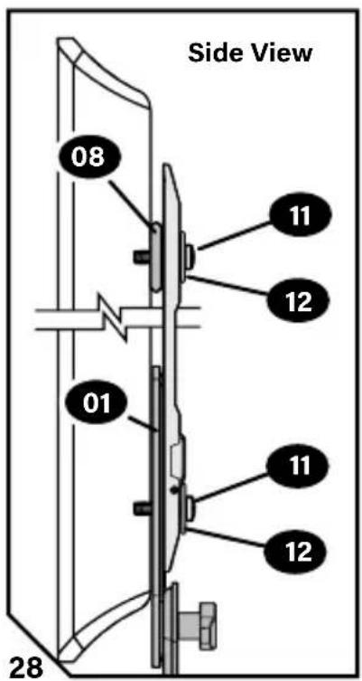
For Rounded or Irregular Back TV
[TV brackets NOT resting flat on your TV]
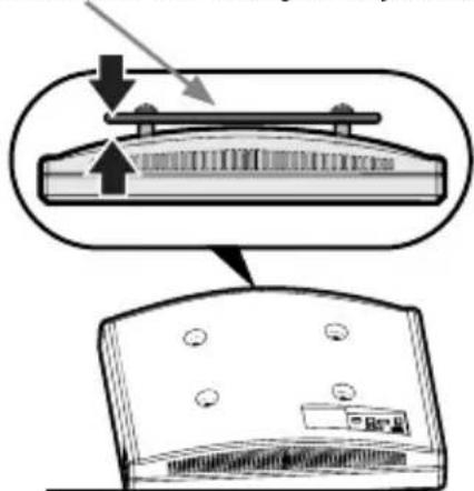
natural_image
Diagram showing a mechanical component with arrows indicating assembly or force direction, no text or symbols present.3.3a
a NO SPACERS 13
text_image
Side View 08 11 12 01 11 12 28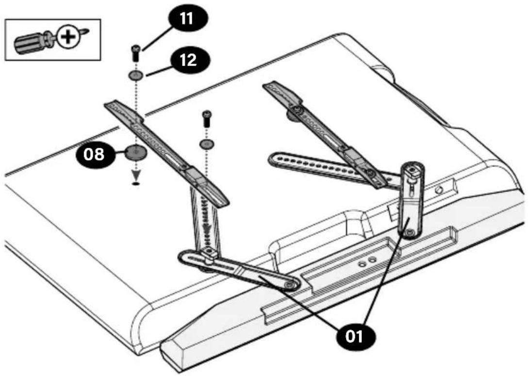
text_image
01 08 12 113.3b

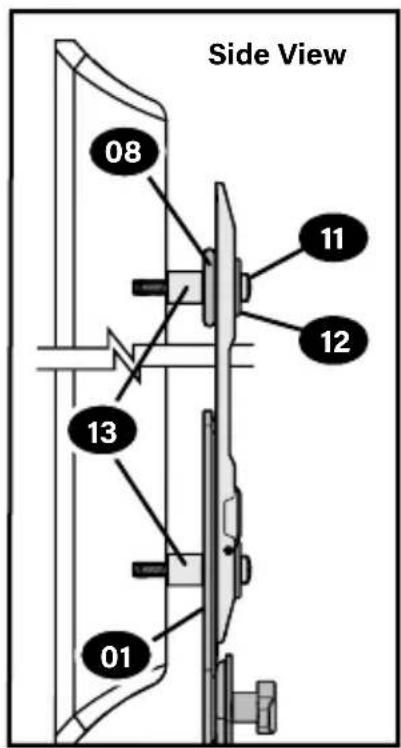
SPACERS 13 NEEDED
text_image
Side View 08 11 12 13 01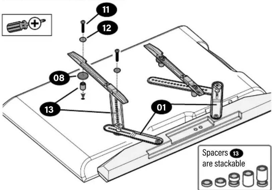
text_image
11 12 08 13 01 Spacers 13 are stackableSTEP 4
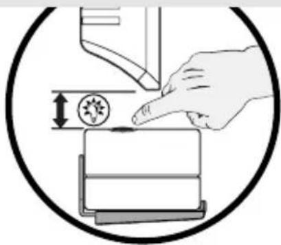
Adjust Soundbar Brackets

NOTE: You may need to position the hole locations in undbar brackets 01 to adjust your undbar to the desired position.

TIP: Leave 1/2" to 1" (2 cm - 3 cm) for microphone or button use.
natural_image
Illustration of a hand pressing down on a mechanical component with a magnified view (no text or symbols)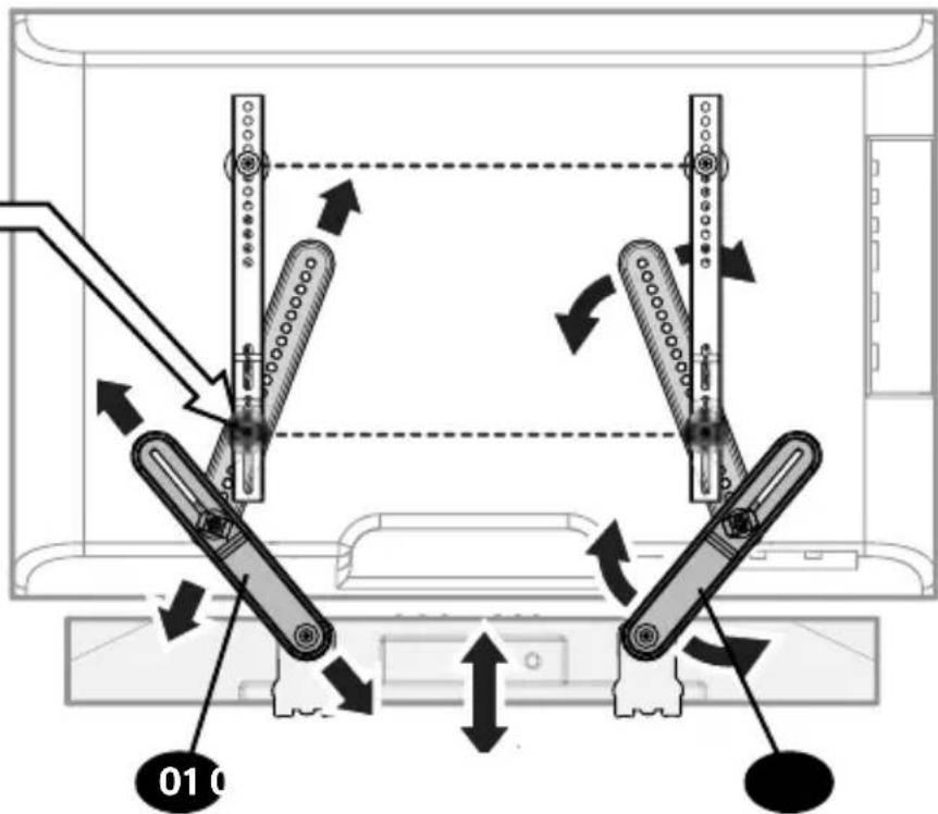
text_image
01 0STEP 5
Tighten Connections
IMPORTANT!
Do not OVER-TIGHTEN the screws
— this will deform the washers.
text_image
Prohibition sign with stethoscope symbol and exclamation mark, commonly used for preventive health or medical education.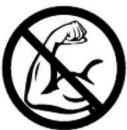
natural_image
Prohibition sign showing a flexed arm crossed out with a diagonal line (no text or symbols)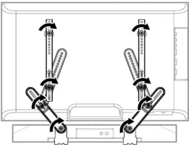
natural_image
Diagram of mechanical linkage systems with bidirectional arrows indicating rotation or force (no text or labels)STEP 6
Hang Up the TV / Soundbar Assembly
Follow your TV wall mount's installation manual to hang your TV assembly.
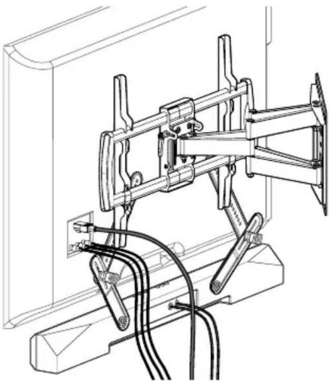
natural_image
Technical line drawing of a mechanical assembly with rods, cables, and mounting base (no text or symbols)for Amazon Fire TV Soundbars
Hang your soundbar onto the Mounting Rings FTV.
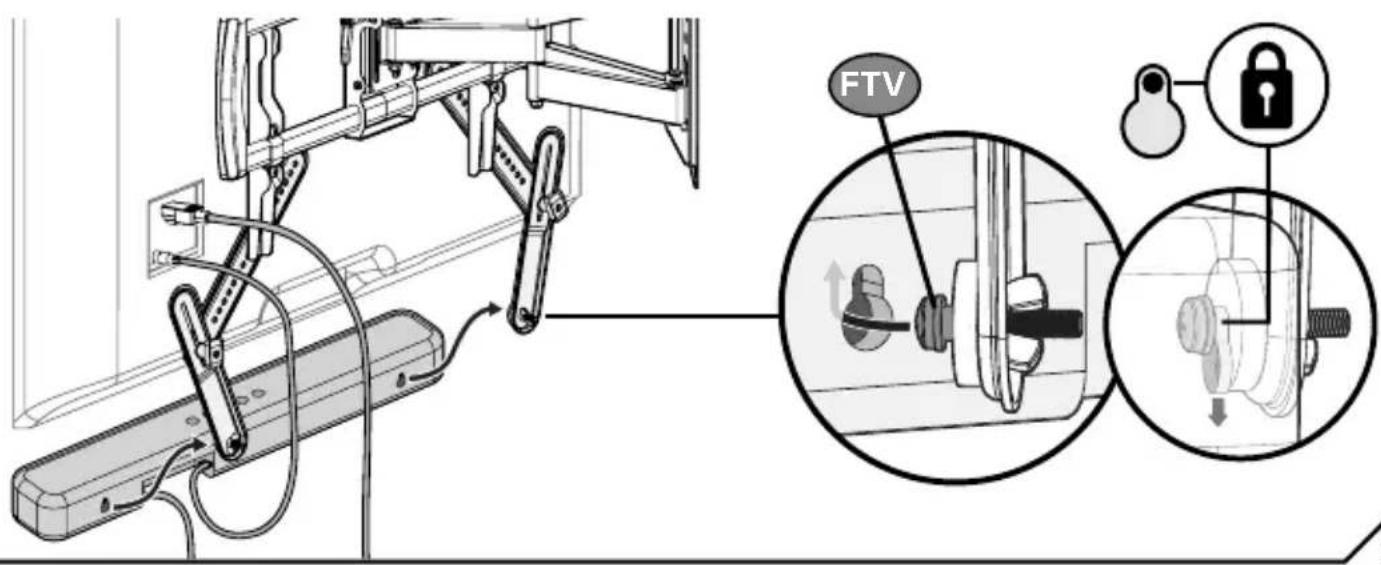
text_image
FTVAdjustments
Loosen tilt knobs Ⓣ to move soundbar mount to desired location, then use included hex key H1 to tighten.
for Amazon Fire TV Soundbars
NOTE: Your Fire TV soundbar does not lock onto the mounting rings FTV - be careful when lifting your soundbar.
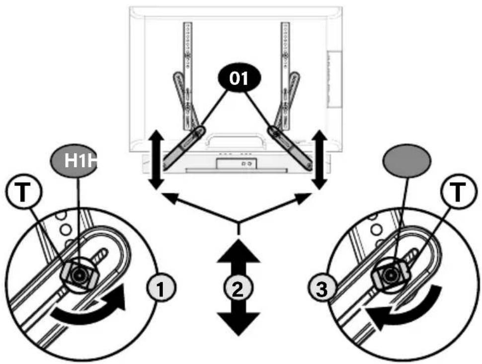
flowchart
graph TD
    A["Device 01"] --> B["H1F"]
    A --> C["T"]
    D["Device 1"] --> E["Control Unit"]
    F["Device 3"] --> G["Control Unit"]
    style A fill:#f9f,stroke:#333
    style D fill:#ccf,stroke:#333
    style F fill:#cfc,stroke:#333
For
Bottom Mounts
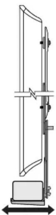
natural_image
Technical line drawing of a vertical mechanical device with a base and mounting bracket (no text or symbols)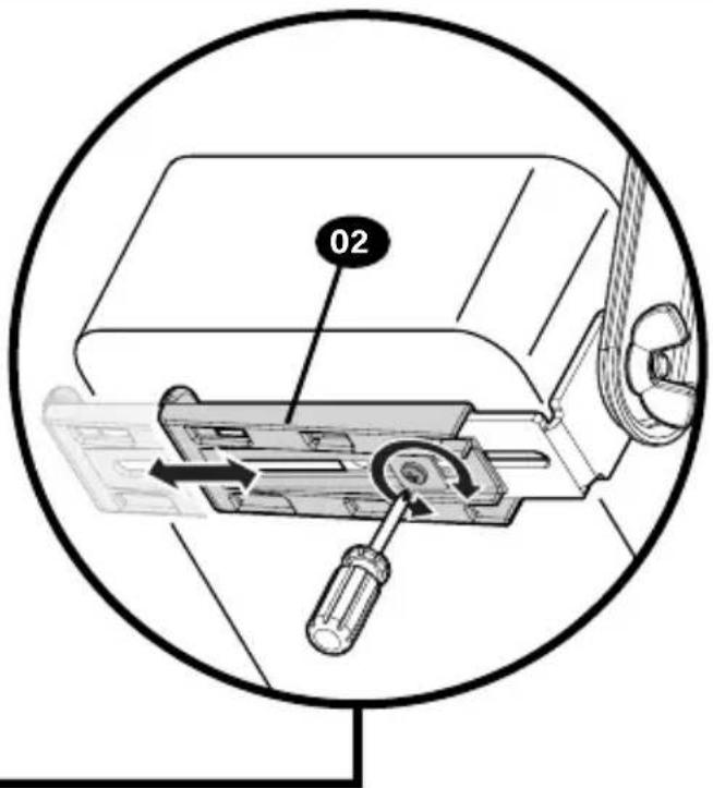
text_image
02Español
WAARSCHUWING: (PAGINA 3)
▲ WARNING: (SIDAN 3)
text_image
SANUS® A Brand of LegendThank you for choosing SANUS!
Please take a moment to let us know how we did:
Legrand AV Inc.
6436 City West Parkway
Eden Prairie, MN 55344 USA
US: +1 (800) 359-5520
Legrand AV Netherlands B.V.
Franklinstraat 14
6003 DK Weert Netherlands
EMEA: +31 (0) 495 580 852
UK: +44 (0) 800 056 2853
Authorized Representative for the UK:
Starline Holding Technology Ltd.
Unit C Island Road
Reading RG2 ORP
©2024 Legrand AV Inc. All rights reserved. SANUS is a brand of Legrand. SANUS and the SANUS logo are registered trademarks of Legrand. Amazon, Fire, and all related marks are trademarks of Amazon.com, Inc. or its affiliates.
Legrand AV Inc. - 6436 City West Parkway - Eden Prairie, MN 55344 USA
6901-603314 00