WSBWM1 - Speaker stands SANUS - Free user manual and instructions
Find the device manual for free WSBWM1 SANUS in PDF.

User questions about WSBWM1 SANUS
0 question about this device. Answer the ones you know or ask your own.
Ask a new question about this device
Download the instructions for your Speaker stands in PDF format for free! Find your manual WSBWM1 - SANUS and take your electronic device back in hand. On this page are published all the documents necessary for the use of your device. WSBWM1 by SANUS.
USER MANUAL WSBWM1 SANUS
natural_image
Technical line drawing of a mechanical assembly with mounting bracket and housing (no text or symbols)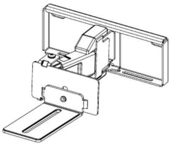
natural_image
Technical line drawing of a mechanical assembly with no visible text or symbolsWE'RE HERE TO HELP
If you have any questions along the way, our install experts are standing by to help.

Call us at: US: +1 (800) 359-5520
EMEA: +31 (0) 495 580 852
UK: +44 (0) 800 056 2853

Or, chat at: US: SANUS.com/chatSP
IMPORTANT SAFETY INSTRUCTIONS
READ ENTIRE MANUAL PRIOR TO USE. SAVE THESE INSTRUCTIONS.
Before getting started, let's make sure this product is perfect for you!
▲ CAUTION: To avoid potential personal injuries and property damage:
- Please read through these instructions completely to be sure you're comfortable with this easy install process.
. This product is designed for use with wood studs, solid concrete and concrete block walls, and drywall only.
Do not use this product for any purpose not explicitly specified by manufacturer.
. Manufacturer is not responsible for damage or injury caused by incorrect assembly or use. - If you do not understand these instructions or have doubts about the safety of the installation, assembly or use of this product, contact Customer Service.
Weight Limit
DO NOT EXCEED

text_image
20 lbs. (9.07 kg)Tools Needed
Drywall Install
Drill Bit
Wood Stud Install
Drill Bit
Concrete Install
13/32 in.
(10 mm)
Concrete

DIMENSIONS
WALL PLATE
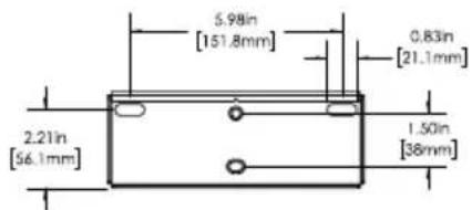
text_image
5.98in [151.8mm] 0.83in [21.1mm] 2.21in [56.1mm] 1.50in [38mm]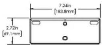
text_image
7.24in [183.8mm] 2.72in [69.1mm]SIDE VIEW - EXTENDED
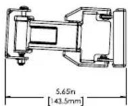
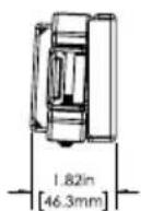
text_image
5.65m [143.5mm]SOUNDBAR INTERFACE
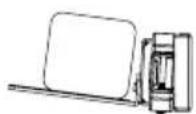
TOP VIEW - RETRACTED

TOP VIEW - EXTENDED
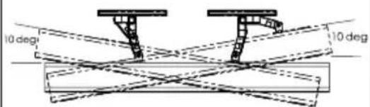
text_image
10 deg 10 degSIDE VIEW RETRACTED
FULLY ASSEMBLED MOUNT
SUPPLIED PARTS AND HARDWARE
WARNING: This product contains small items that could be a choking hazard if swallowed.
Before starting assembly, verify all parts are included and undamaged. If any parts are missing or damaged, DO NOT return the damaged item to your dealer; Contact Sanus (See back page).
Never use damaged parts!

NOTE: Not all hardware included in this kit will be used.
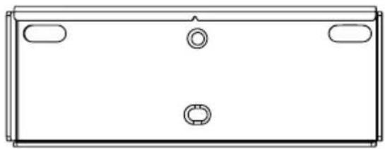
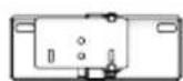
natural_image
Simple line drawing of a rectangular box with four corner handles and three circular cutouts (no text or symbols)Wall Plate
1 (qty. 2)
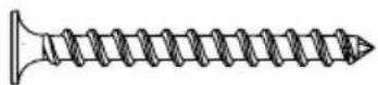
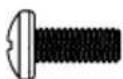
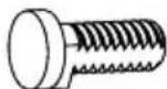
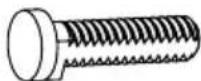
08 Screw
2 (qty. 4)
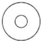
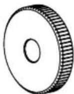
Washer (#8 Screw)
3 (qty. 4)
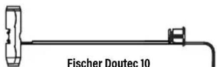
text_image
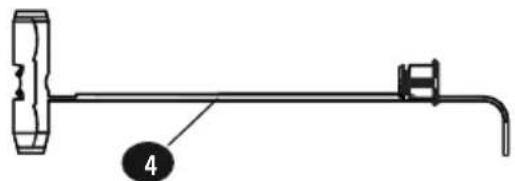
Fischer Doutec 10Fischer Doutec 10 Drywall/Concrete Anchor
4 (qty. 4)
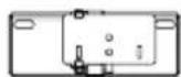
natural_image
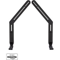
Technical line drawing of a mechanical component with mounting holes and housing (no text or symbols)Left Soundbar Bracket
5 (qty. 1)
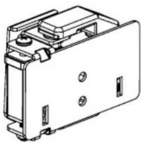
natural_image
Technical line drawing of a mechanical component or enclosure with mounting holes and internal structure (no text or symbols)Right Soundbar Bracket
6 (qty. 1)
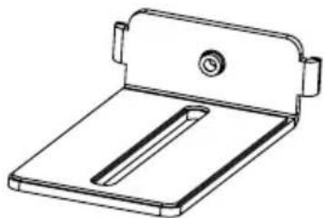
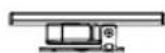
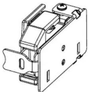
natural_image
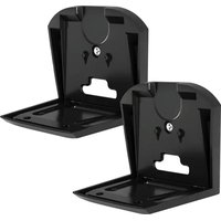
Line drawing of a mechanical clamp or bracket with a circular knob and rectangular base (no text or symbols)Under Mounting Bracket
7 (qty. 2)

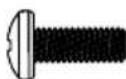
M5 X 8mm Screw
8 (qty. 2)

M4 Screw
9 (qty. 2)
M4 Short Screw
(M4 X 10 mm)

M5 Short Screw
(M5 X 10 mm)
M6 Screw
(M6 X 16 mm)
Soundbar Screws
(Only one size fits your Soundbar)
10 (qty. 2 each)
M4 Long Screw
(M4 X 16 mm)
M5 Long Screw
(M5 X 16 mm)
1/4-20 Screw
Washer
11 (qty. 2)
Spacer
12 (qty. 4)
Short Keyhole Screw
13 (qty. 2)
Long Keyhole Screw
14 (qty. 2)
Keyhole Nut
15 (qty. 2)
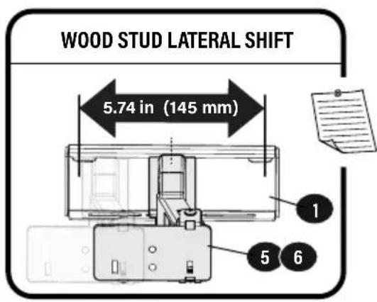
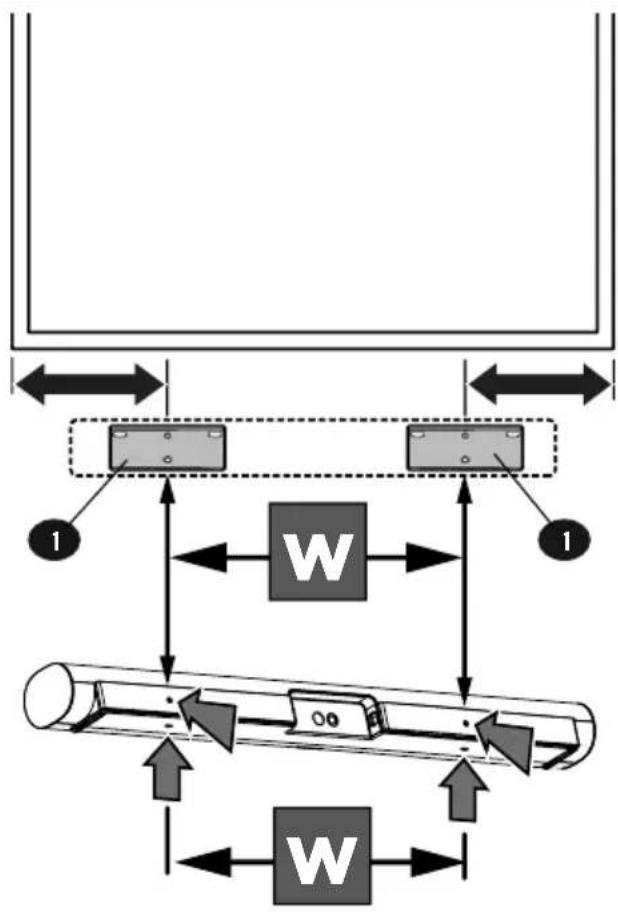
1 WIDTH LOCATION
text_image
WOOD STUD LATERAL SHIFT 5.74 in (145 mm) 1 5 6The width W between the center of the wall plates 1 should match the width of the space between the soundbar mounting holes.
flowchart
graph TD
    A["Component 1"] --> B["Load W"]
    C["Component 2"] --> D["Load W"]
    B --> E["Return to Component 1"]
    D --> F["Return to Component 2"]
    E --> G["Return to Component 3"]
    F --> H["Return to Component 4"]
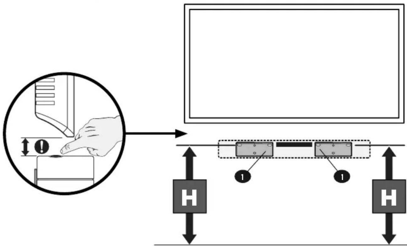
2 HEIGHT LOCATION
text_image
Diagram illustrating a hand operating a computer monitor with labeled components and directional arrows indicating movement or control.IMPORTANT

Wall plates
1 MUST be placed at equal heights.
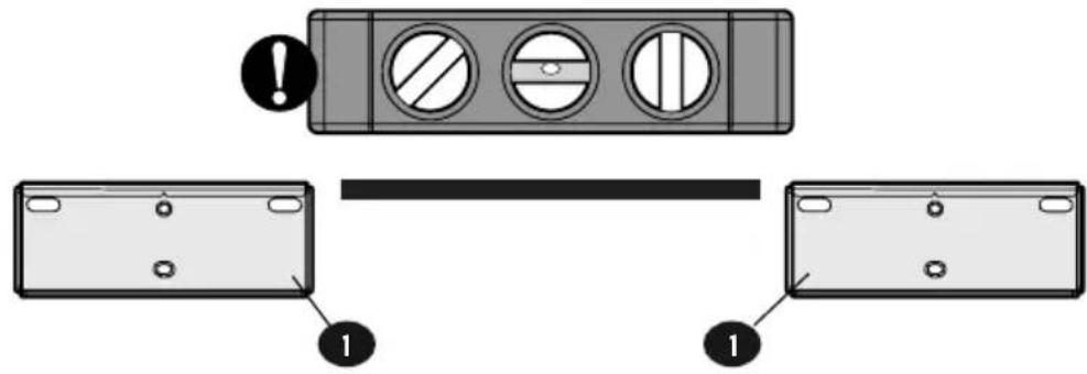
text_image
Diagram showing a device panel with warning symbols and labeled parts, including a warning icon and numbered annotations.
Note the orientation
of Wall plates 1.
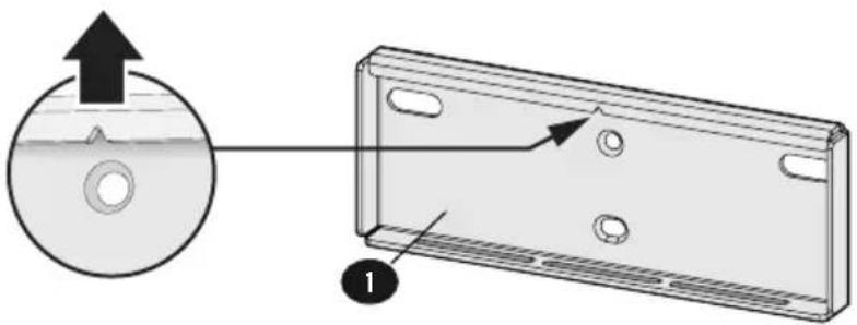
text_image
Diagram showing a CD or DVD disc with an arrow pointing to a rectangular panel, labeled with number 1.
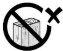
Use anchors 4
for drywall or concrete only.
DO NOT USE
with wood studs.
natural_image
Pure mechanical diagram of a lever with a labeled component (no text or symbols)Follow the step for your wall type:
natural_image
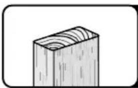
Simple line drawing of a wooden block with visible grain patterns (no text or symbols)For WOOD STUD
Go to STEP 2A on PAGE 6
natural_image
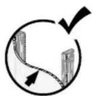
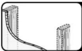
Diagram of a curved road or pipeline segment between two vertical buildings (no text or symbols)For DRYWALL ONLY, or UNSURE of stud location
Go to STEP 2B on PAGE 7
natural_image
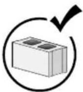
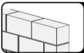
Simple line drawing of stacked bricks (no text or symbols)For CONCRETE Block / Solid Concrete
Go to STEP 2C on PAGE 9
▲CAUTION: Avoid potential personal injury or property damage!
● Drywall covering the wall must not exceed 5/8 in. (1.5 cm)
- Minimum wood stud size: nominal 2 x 4 in. (5.1 x 10.2 cm) actual 1 ½ x 3 ½ in. (3.8 x 8.9 cm)
• Stud centers must be verified
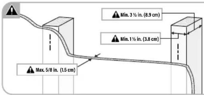
text_image
Max. 5/8 in. (1.5 cm) Min. 3 ½ in. (8.9 cm) Min. 1 ½ in. (3.8 cm)
NOTE: This installation is for mounting wall plate to a confirmed wooden stud.
See Step 2B for drywall installation without a confirmed wooden stud.
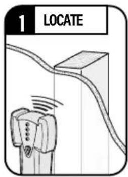
text_image
1 LOCATE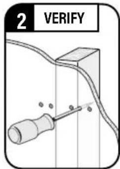
text_image
2 VERIFY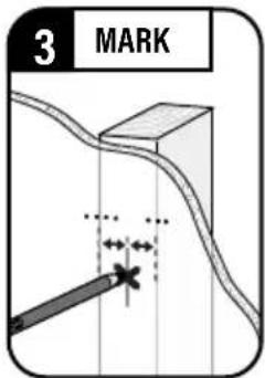
text_image
3 MARK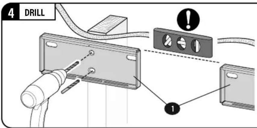
text_image
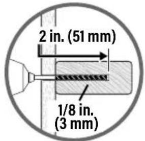
4 DRILL 1Use wall plates ① as a guide. Drill 1/8 in. (3 mm) holes to a depth of 2 inches.
text_image
2 in. (51 mm) 1/8 in. (3 mm)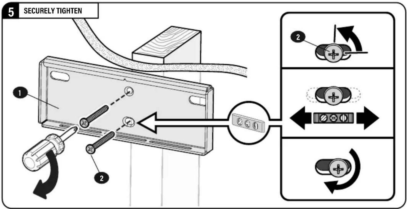
text_image
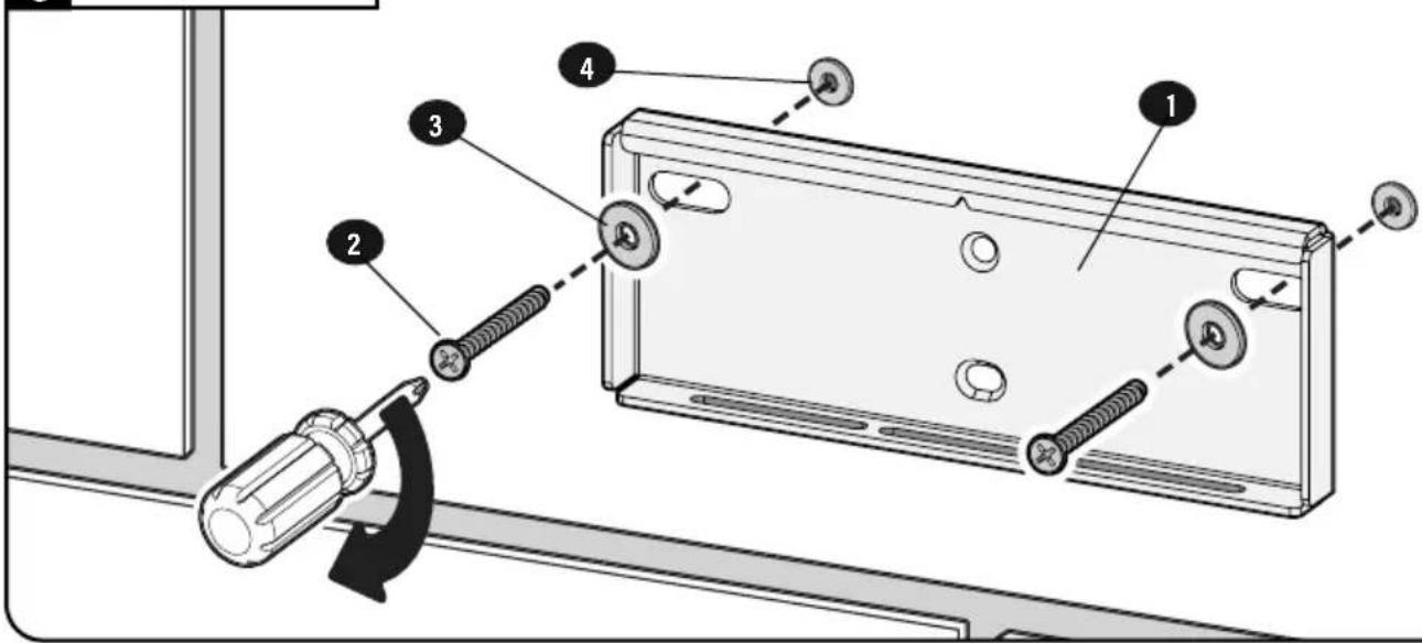
5 SECURELY TIGHTEN 1 2 2CAUTION: Avoid potential personal injury or property damage!
● Drywall covering the wall must not exceed 1/2 in. (1.2 cm).
- IMPORTANT: Ensure wall plates 1 are level before drilling.
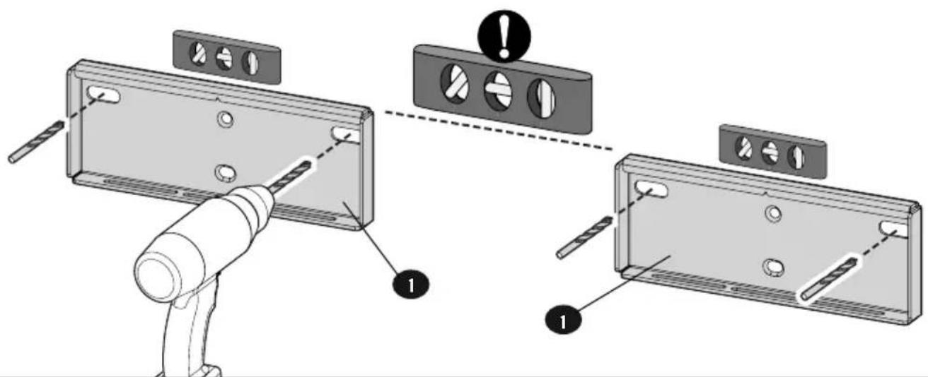
1 DRILL PILOT HOLES
Use wall plates 1 as a guide. Drill 1/8 in. (3 mm) pilot holes to verify your wall.
text_image
Technical diagram showing installation of a device panel with labeled components and warning indicators2 VERIFY WALL
If pilot hole
is located
ON A STUD,
proceed to
Step 5 on PAGE 8.
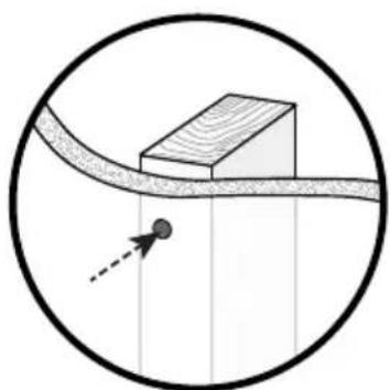
natural_image
Simple line drawing of a rectangular block on a curved surface with a dashed arrow pointing to it, enclosed in a circle (no text or symbols)If pilot hole is located in DRYWALL ONLY,
proceed to
Step 3 below.
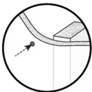
natural_image
Diagram showing a curved pipe with a dashed arrow indicating direction, enclosed in a circle (no text or symbols)3 DRILL DRYWALL
Drill 13/32 in. (10 mm) holes in pilot holes located in drywall.
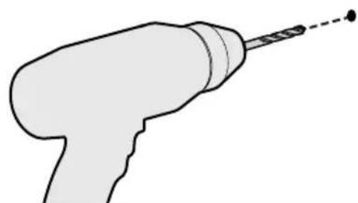
natural_image
Simple line drawing of a handheld electric drill (no text or symbols)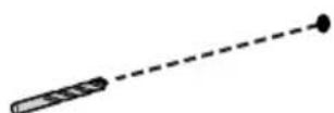
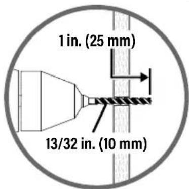
text_image
1 in. (25 mm) 13/32 in. (10 mm)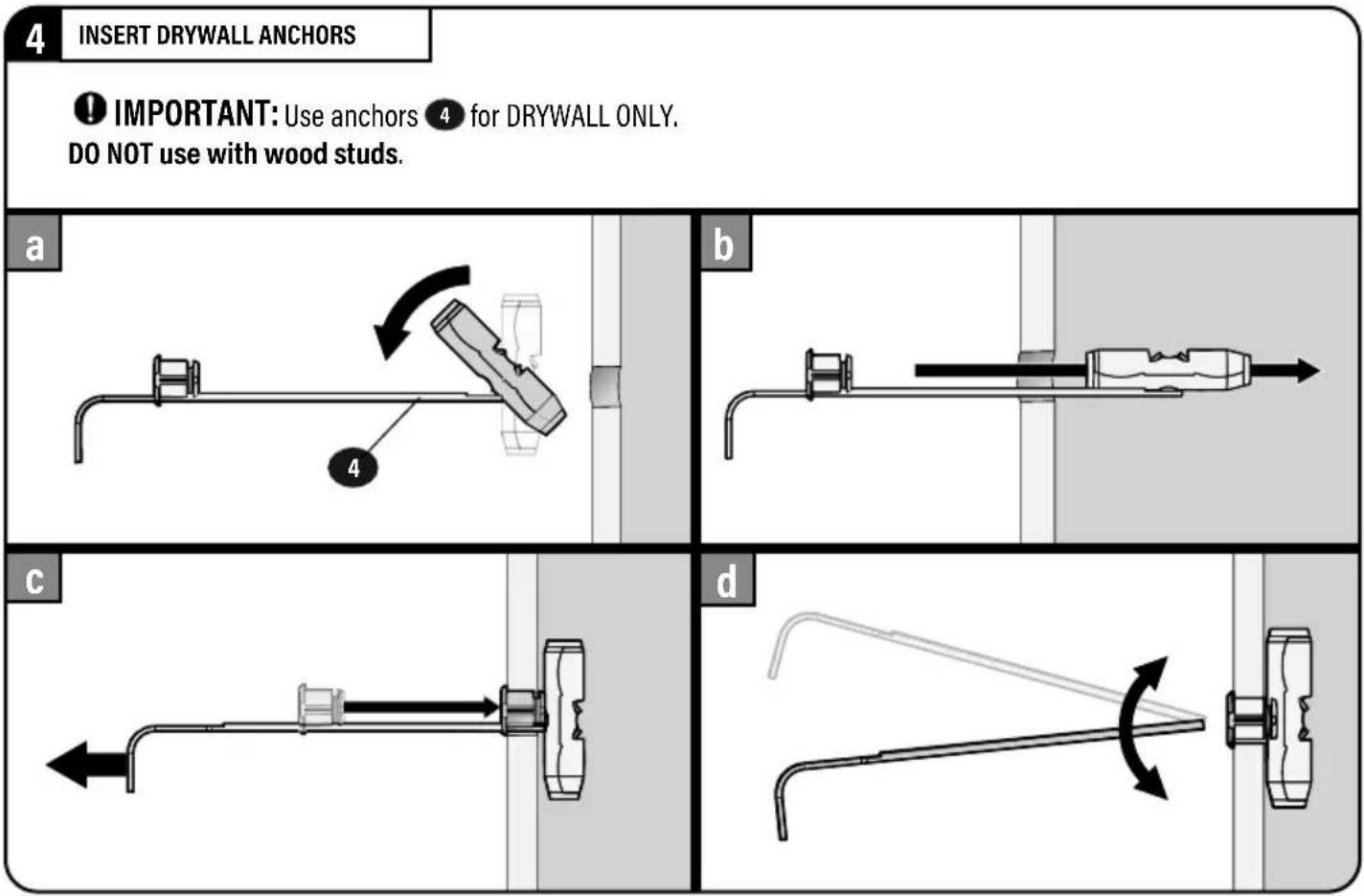
text_image
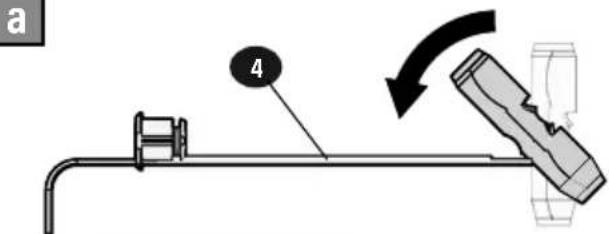
4 INSERT DRYWALL ANCHORS ① IMPORTANT: Use anchors ④ for DRYWALL ONLY. DO NOT use with wood studs. a b c d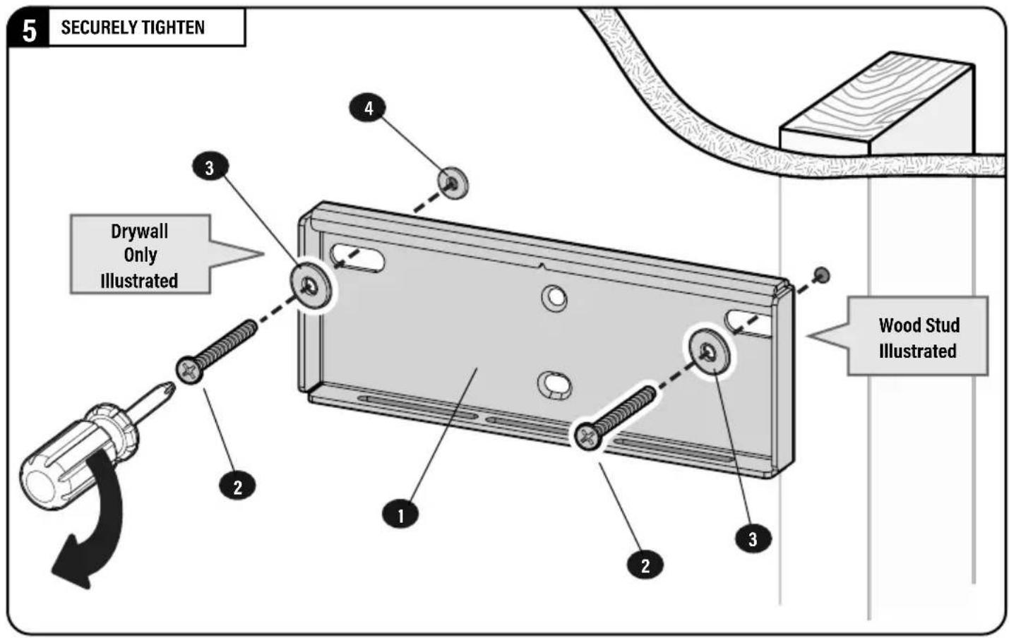
text_image
5 SECURELY TIGHTEN Drywall Only Illustrated Wood Stud IllustratedCAUTION: Avoid
potential personal injury or property damage!
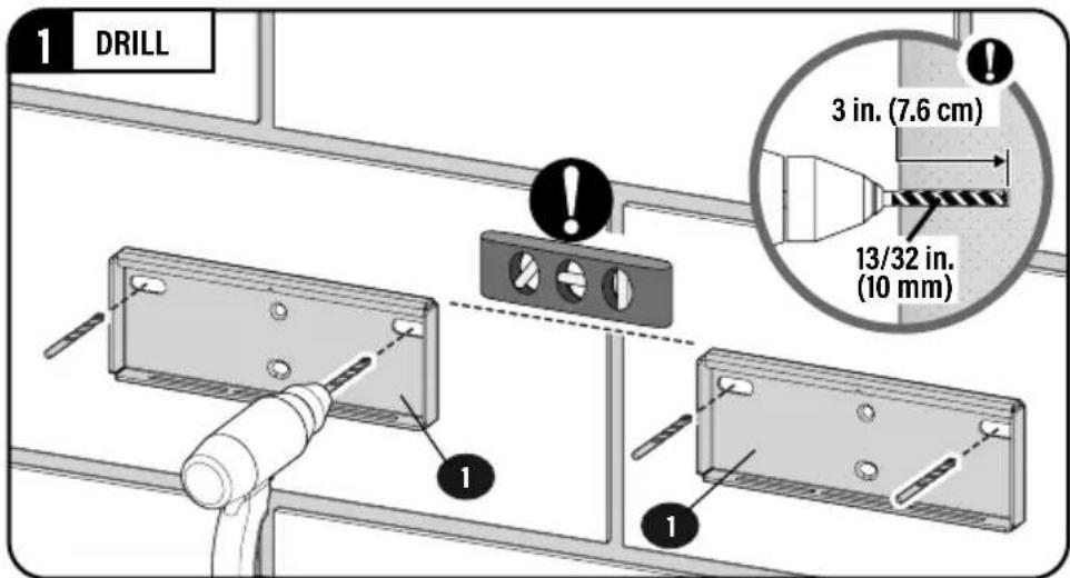
● Minimum solid concrete thickness: 8 in. (20.3 cm)
● Minimum concrete block size: 8 x 8 x 16 in. (20.3 x 20.3 x 40.6 cm)
IMPORTANT: Ensure wall plates 1 are level before drilling.
text_image
1 DRILL 3 in. (7.6 cm) 13/32 in. (10 mm) 12 INSERT CONCRETE ANCHORS
text_image
a 4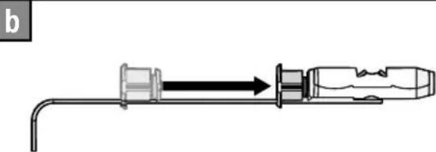
natural_image
Diagram of a mechanical device with a pipe and connector, showing directional flow (no text or symbols)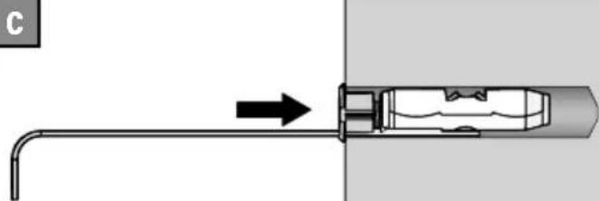
natural_image
Diagram of a mechanical component with an arrow indicating direction, no text or symbols present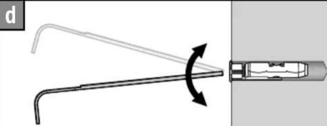
natural_image
Diagram showing a mechanical component with a curved arm and a cylindrical shaft, connected by directional arrows (no text or symbols)3 SECURELY TIGHTEN
text_image
Technical diagram showing a mechanical assembly with numbered components and a tool interacting with a component.STEP 3
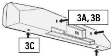
ATTACH SOUNDBAR TO SOUNDBAR MOUNTS
Look at the mounting holes on the BACK or BOTTOM of your soundbar to determine your install method 3A, 3B or 3C.
text_image
3A, 3B 3C
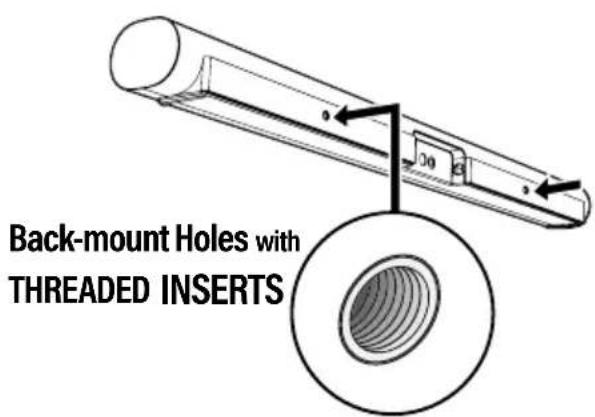
STEP 3A: (PAGE 10) Back-mount Holes with THREADED INSERTS

STEP 3B: (PAGE 10) Back-mount Holes with KEY HOLE SLOTS
STEP 3C: (PAGE 10) Bottom-mount Holes
3A
BACK-MOUNTED SCREWS
text_image
Back-mount Holes with THREADED INSERTS1 OPEN
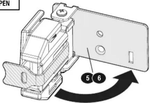
text_image
OPEN 5 62
ATTACH
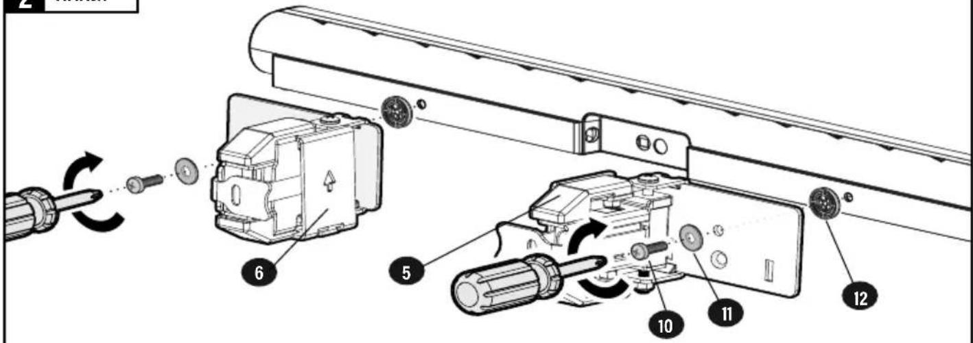
text_image
Technical diagram showing exploded view of a mechanical assembly with numbered components and directional arrows indicating motion or assembly.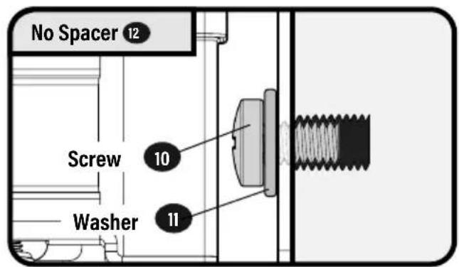
text_image
No Spacer 12 Screw 10 Washer 11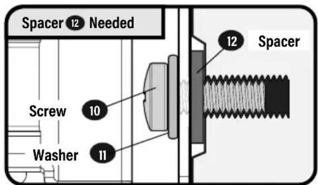
text_image
Spacer 12 Needed Screw 10 Washer 11 12 Spacer3B
BACK-MOUNTED KEYHOLE SCREWS
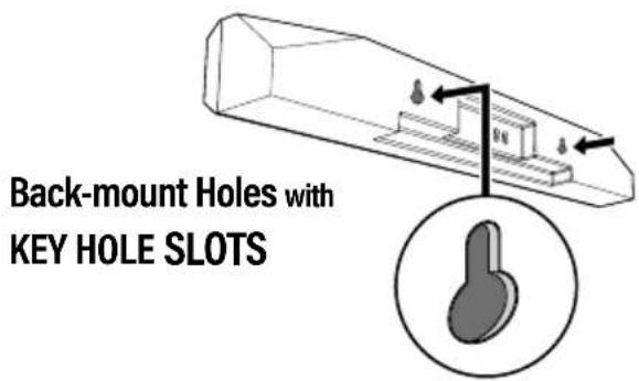
text_image
Back-mount Holes with KEY HOLE SLOTS1 OPEN
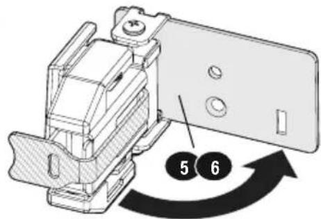
text_image
Technical diagram showing a mechanical assembly with numbered components and directional arrows indicating motion or assembly.2 ASSEMBLE
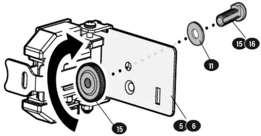
text_image
Technical diagram of a camera assembly with numbered components and directional arrows indicating motion or assembly.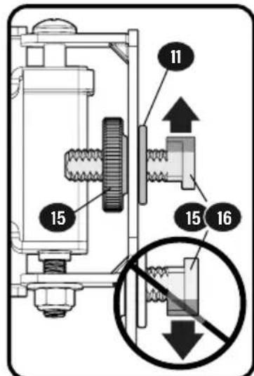
text_image
15 11 15 163 ATTACH
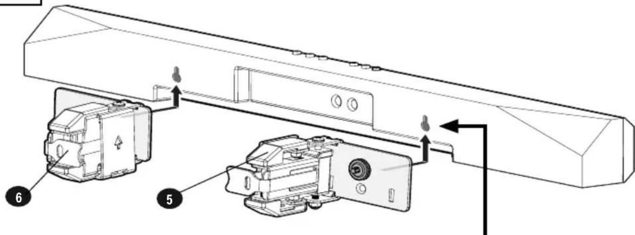
text_image
Technical diagram showing exploded view of a mechanical assembly with labeled components 5 and 6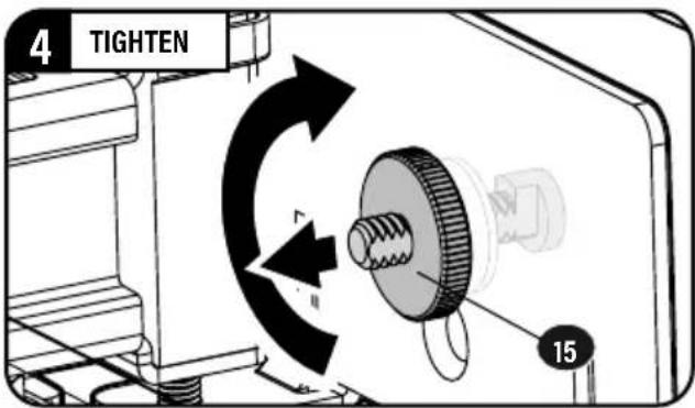
text_image
4 TIGHTEN 15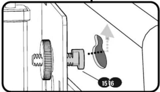
text_image
15 163C
BOTTOM-MOUNTED SCREWS

text_image
Bottom-mount Holes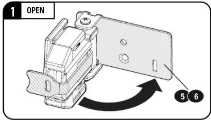
text_image
1 OPEN 5 62 ASSEMBLE
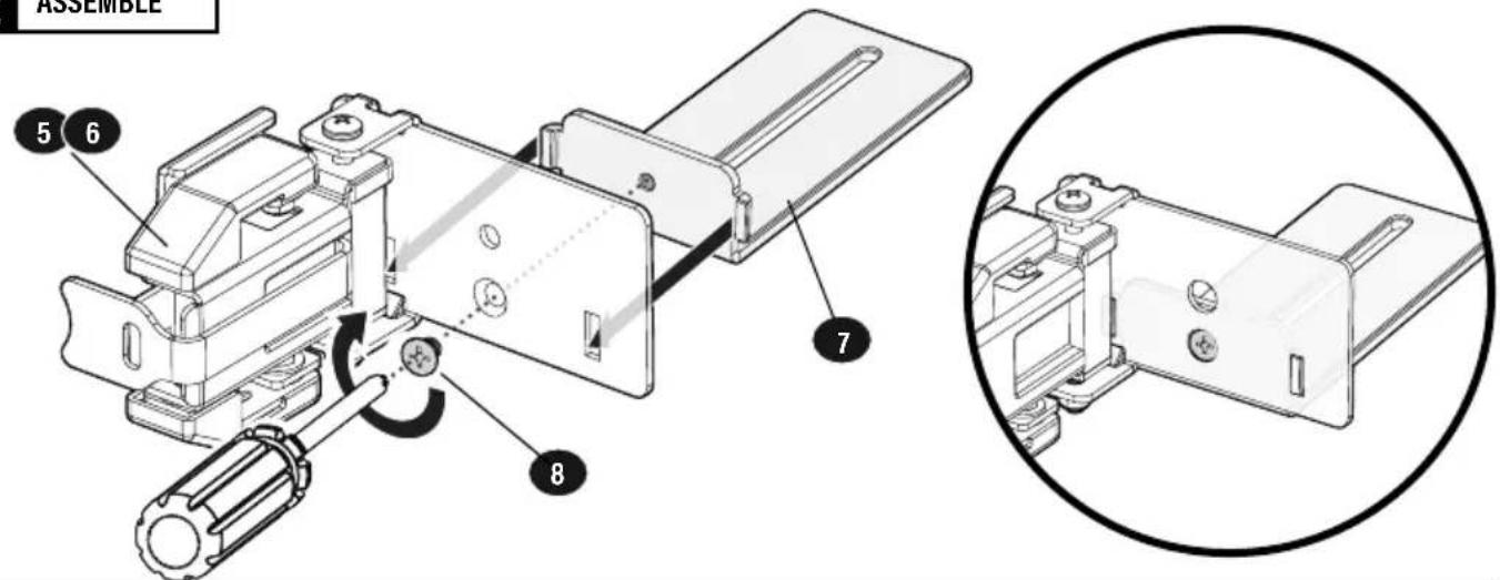
text_image
ASSEMBLE 5 6 7 83 ATTACH
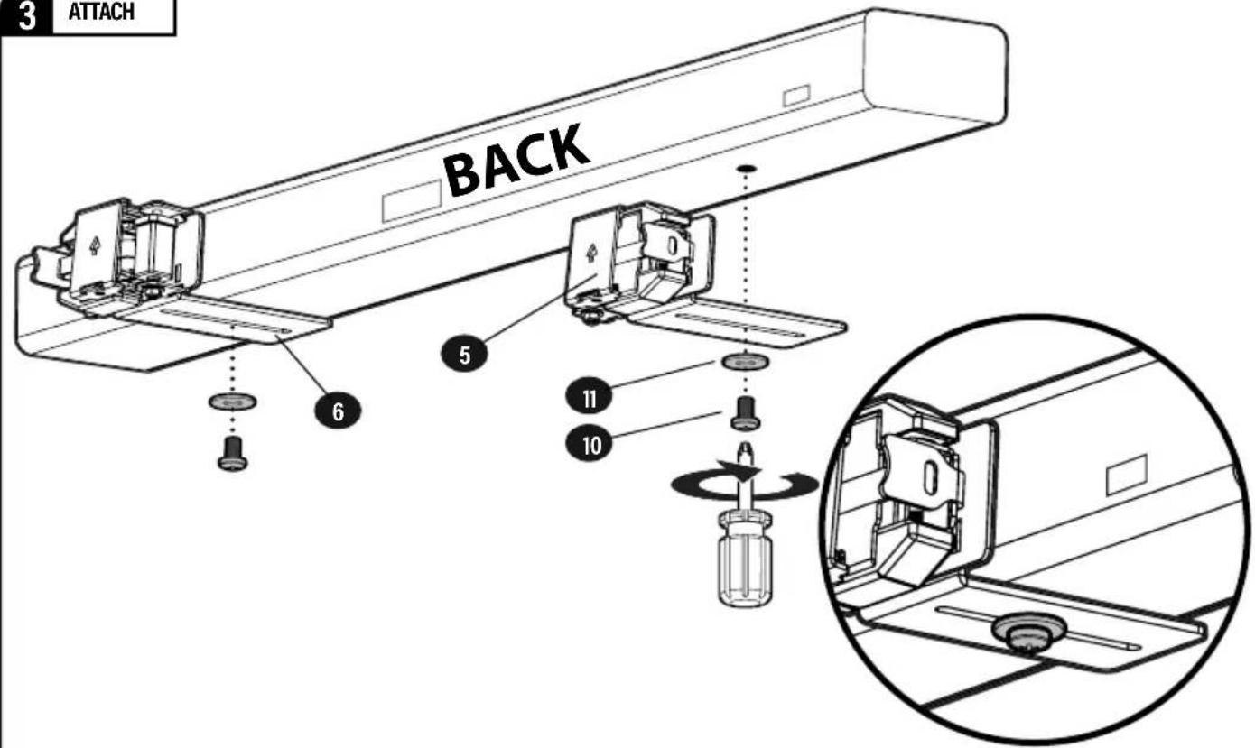
text_image
3 ATTACH BACK 5 6 11 10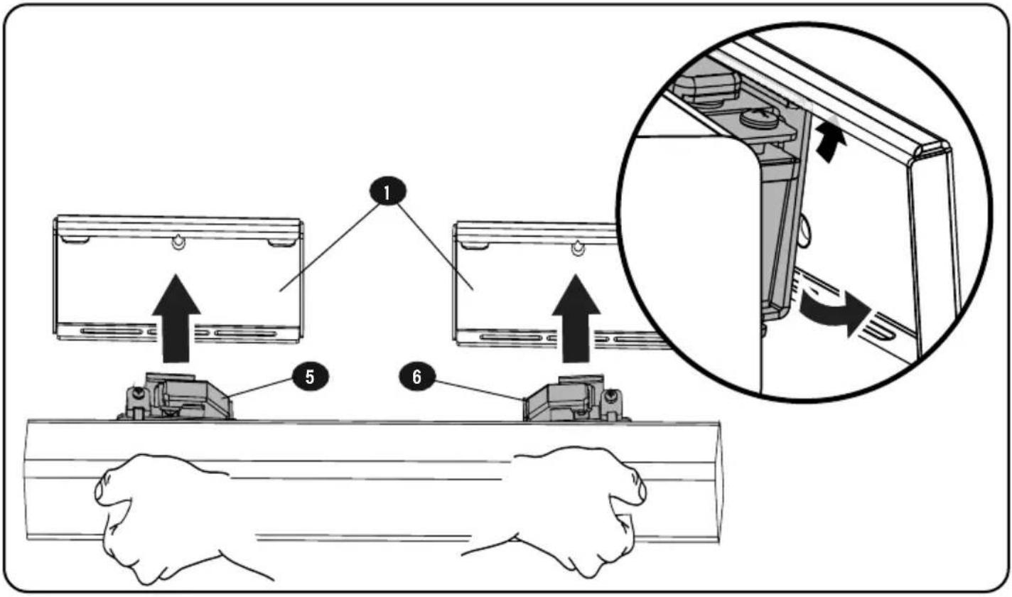
text_image
Diagram illustrating the process of installing or adjusting a wall-mounted air conditioner panel, with numbered steps and an inset showing the component being removed.STEP 5
SECURE SOUNDBAR
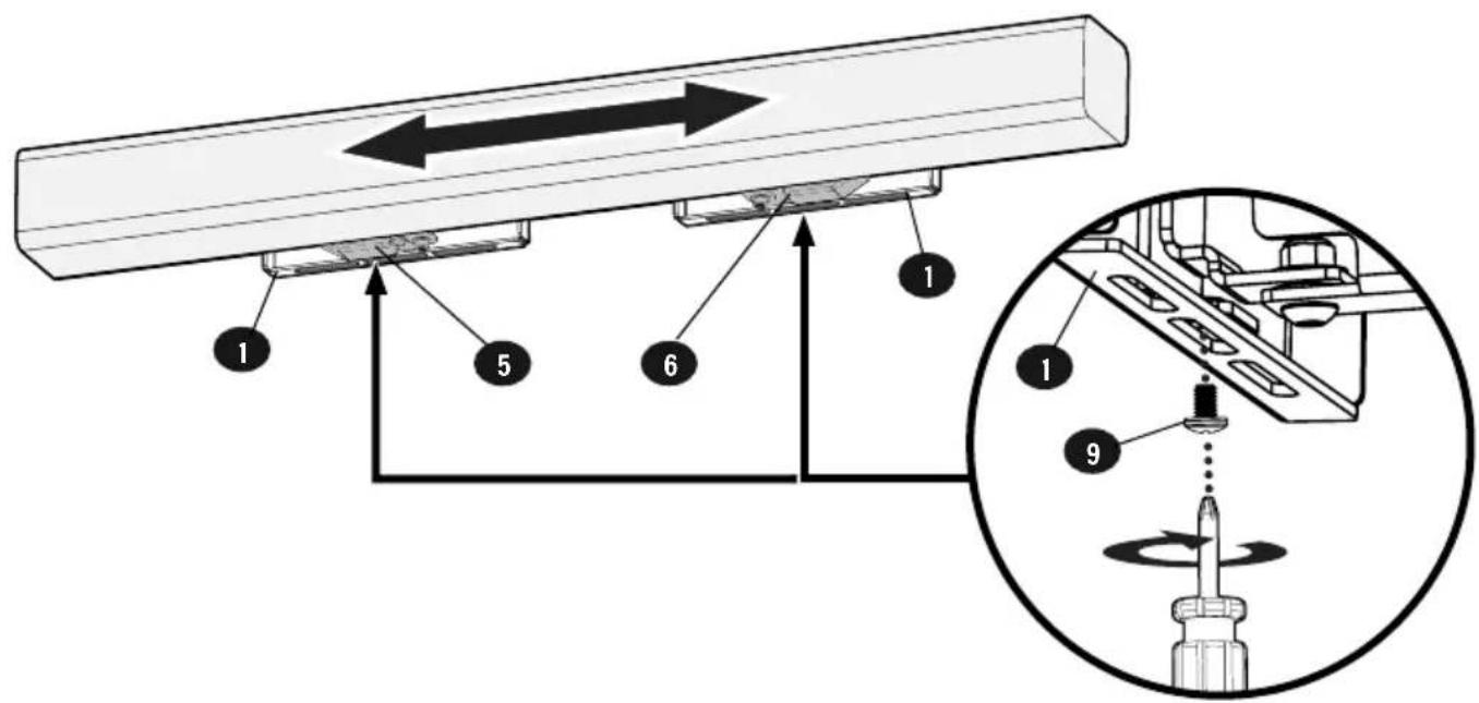
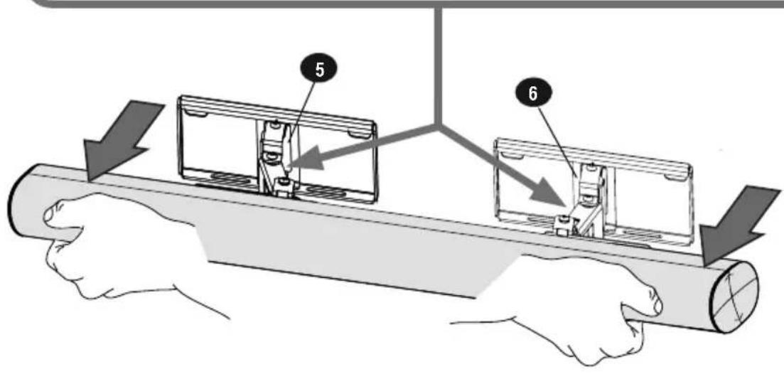
IMPORTANT:
Soundbar mounts 5 / 6 must stay centered on wall plates 1 for drywall installation.
text_image
Technical diagram showing a mechanical assembly with numbered components and a magnified view of the component being threaded.ADJUSTMENTS
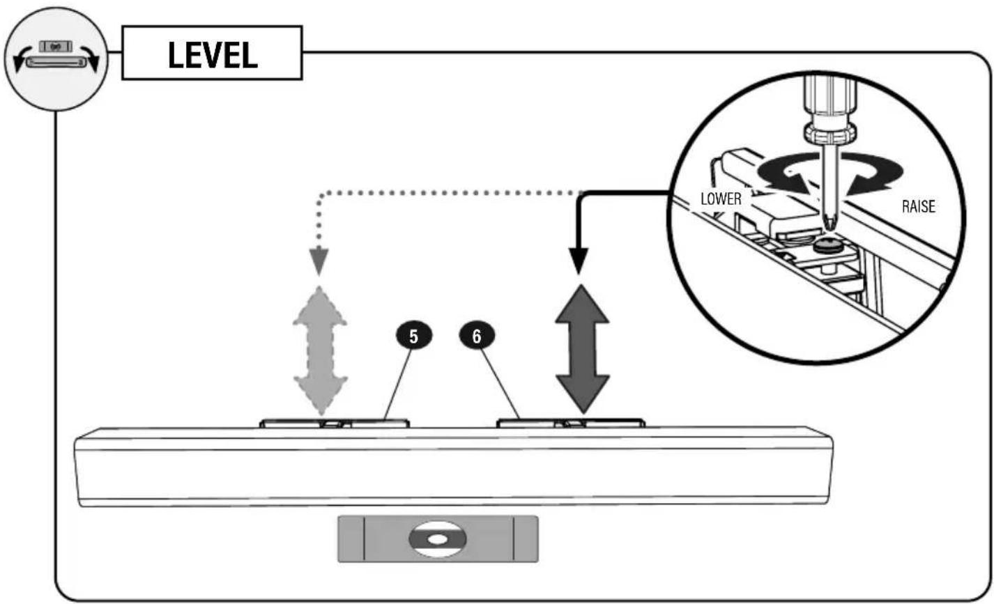
flowchart
graph TD
    A["LEVEL"] --> B["Lower"]
    B --> C["RAISE"]
    C --> D["Step 5"]
    C --> E["Step 6"]
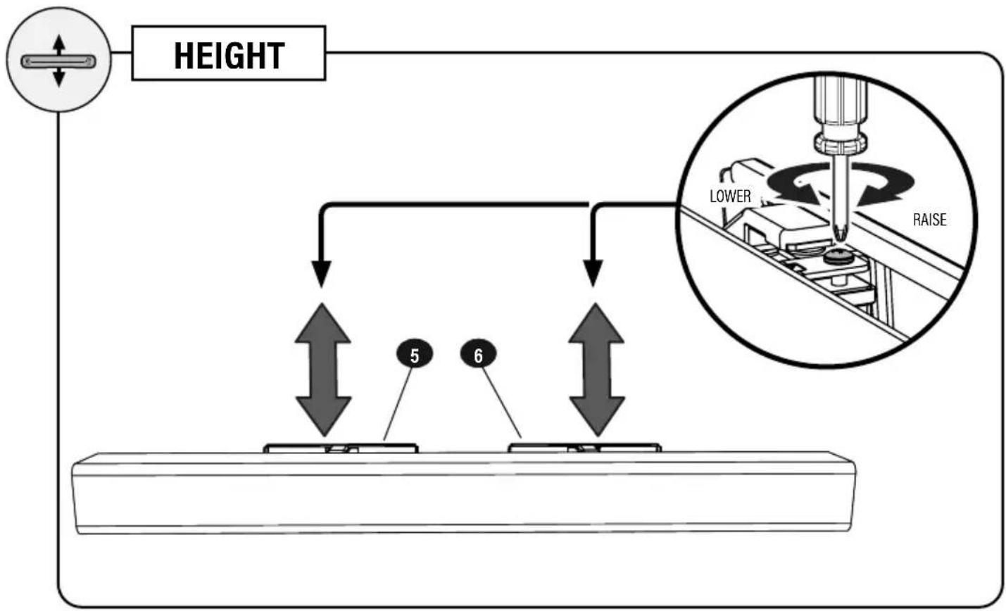
text_image
HEIGHT 5 6 LOWER RAISE
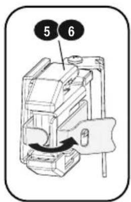
EXTEND and RETRACT

NOTE: Remove the hook and loop teners around the soundbar mounts FORE extending the soundbar.
The fasteners were intended to keep the soundbar mounts stationary during installation.

TIP: Use these fasteners for able management.
text_image
5 6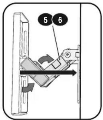
text_image
5 6
CAUTION: Avoid potential personal injury or property damage!
The brackets contain potential pinch points during operation. Keep fingers away from pinch points when retracting the brackets.
text_image
Diagram illustrating a mechanical assembly with labeled components and directional arrows indicating movement or force.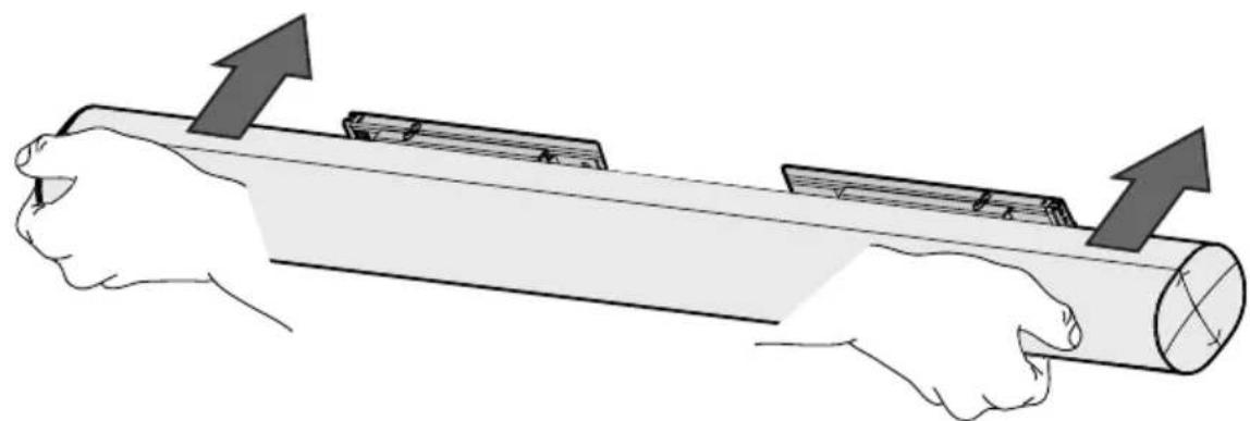
natural_image
Illustration of two hands pulling a cylindrical object with upward arrows indicating motion (no text or symbols)- BREEDTE W 2. HOOGTE H
BLADZIJDE 4
STAP 2 DE SOUNDBARBEUGEL AAN DE MUUR BEVESTIGEN
BLADZIJDE 5
BELANGRIJK:
- BREDDEN W 2. HÖJD H.
SIDAN 4
STEG 2 FÄST LJUDSPELARFÄSTEN PÅ VÄGGEN
SIDAN 5
VIKTIGT:
Betongblock/Solidbetonginstallation → SIDAN 9
2A

Betongblock/Solidbetonginstallation
SIDAN 9
Thank you for choosing Sanus! Please take a moment to let us know how we did:
Legrand AV Inc.
6436 City West Parkway
Eden Prairie, MN 55344 USA
US: +1 (800) 359-5520
SANUS.com
Legrand AV Netherlands B.V.
Franklinstraat 14, 6003 DK Weert Netherlands
EMEA: +31 (0) 495 580 852
UK: +44 (0) 800 056 2853
SANUS.com
Authorized Representative for the UK
Starline Holding Technology Ltd. Unit C Island Road Reading RG2 ORP UK