WSWME11 - Speaker stands SANUS - Free user manual and instructions
Find the device manual for free WSWME11 SANUS in PDF.

User questions about WSWME11 SANUS
0 question about this device. Answer the ones you know or ask your own.
Ask a new question about this device
Download the instructions for your Speaker stands in PDF format for free! Find your manual WSWME11 - SANUS and take your electronic device back in hand. On this page are published all the documents necessary for the use of your device. WSWME11 by SANUS.
USER MANUAL WSWME11 SANUS
natural_image
Technical line drawing of a mechanical device with a circular base and handle (no text or symbols)We'll Make It Stress-Free
If you have any questions along the way, just give us a call.
US: +1 (800) 359-5520 · EMEA: +31 (0) 495 580 852 · UK: +44 (0) 800 056 2853
We're ready to help!
IMPORTANT SAFETY INSTRUCTIONS
— PLEASE READ ENTIRE MANUAL PRIOR TO USE — SAVE THESE INSTRUCTIONS
Before getting started, let's make sure this product is perfect for you!
This mount is designed to support only Sonos® Era 100™ speakers.
CAUTION: Avoid potential personal injuries and property damage!
- Check your speaker owner's manual to see if there are any special requirements for mounting your speaker.
- Please read through these instructions completely to be sure you're comfortable with this easy install process.
- Do not use this product for any purpose not explicitly specified by manufacturer.
- Manufacturer is not responsible for damage or injury caused by incorrect assembly or use.
- The wall must be capable of supporting five times the weight of the speaker and mount combined.
- If you do not understand these instructions or have doubts about the safety of the installation, assembly or use of this product, contact Customer Service at +1 (800) 359-5520 (EMEA: +31 (0) 495 580 852; UK: +44 (0) 800 056 2853).
Speaker Weight Limit DO NOT EXCEED

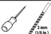
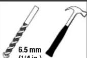
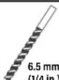
Tools Needed
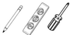
Pencil Level
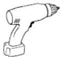
Electric Drill
Wood Stud Install

Stud Finder
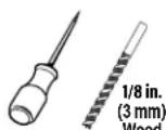
Awl
Concrete Install

Hammer Drill Bit
Drywall Install

Hammer Drill Bit
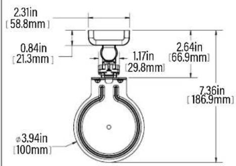
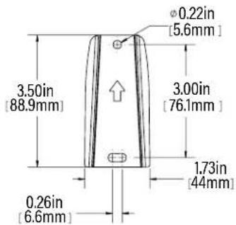
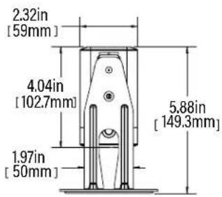
Dimensions
TOP VIEW
text_image
2.31in [58.8mm] 0.84in [21.3mm] 1.17in [29.8mm] 2.64in [66.9mm] 7.36in [186.9mm] Ø3.94in [100mm]WALL PLATE
text_image
0.22in [5.6mm] 3.50in [88.9mm] 3.00in [76.1mm] 1.73in [44mm] 0.26in [6.6mm]3-D
natural_image
Technical line drawing of a mechanical device with a circular base and lever mechanism (no text or symbols)FRONT VIEW
text_image
2.32in [59mm] 4.04in [102.7mm] 1.97in [50mm] 5.88in [149.3mm]SIDE VIEW - TILT
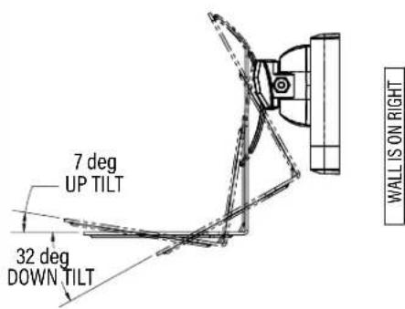
text_image
7 deg UP TILT 32 deg DOWN TILT WALL IS ON RIGHTTOP VIEW - SWIVEL
WALL IS ON TOP
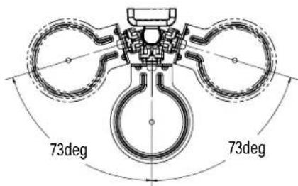
text_image
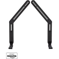
73deg 73degSupplied Parts and Hardware
⚠ WARNING: This product contains small items that could be a choking hazard if swallowed.
Before starting assembly, verify all parts are included and undamaged. If any parts are missing or damaged, do not return the damaged item to your dealer; contact Customer Service. Never use damaged parts!
Quantities shown are for one speaker mount.
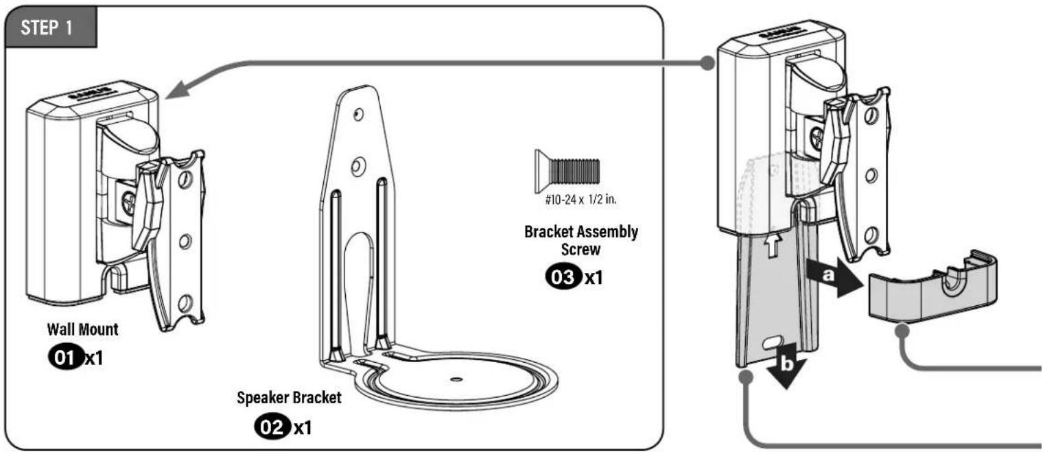
text_image
STEP 1 Wall Mount 01 x1 Speaker Bracket 02 x1 #10-24 x 1/2 in. Bracket Assembly Screw 03 x1 a b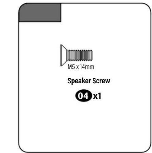
text_image
M5 x 14mm Speaker Screw 04 x1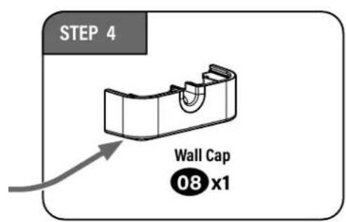
text_image
STEP 4 Wall Cap 08 x1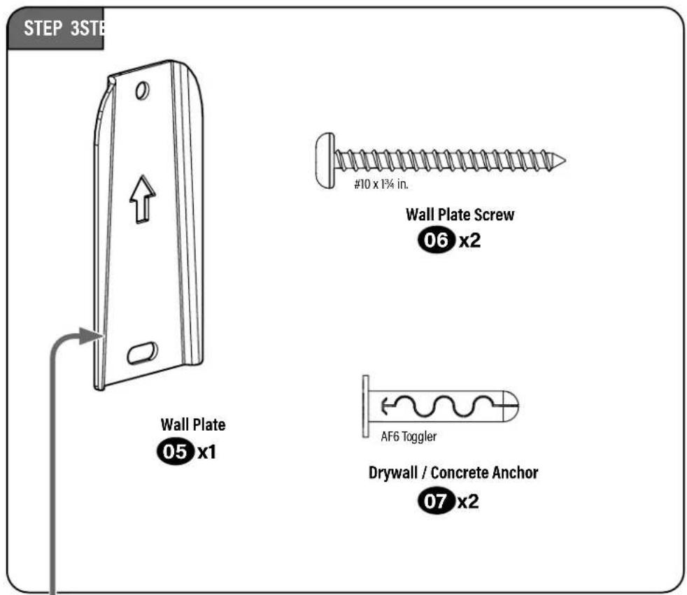
text_image
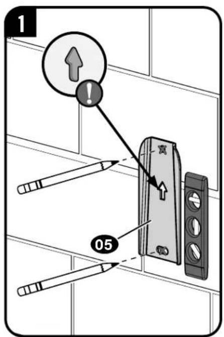
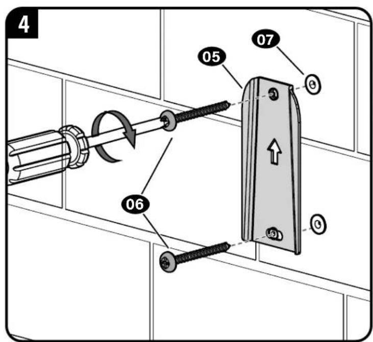
STEP 3STB Wall Plate 05 x1 #10 x 1¾ in. Wall Plate Screw 06 x2 AF6 Toggler Drywall / Concrete Anchor 07 x2STEP 1
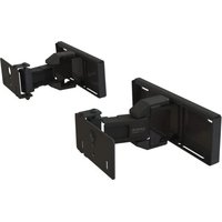
Assemble Brackets
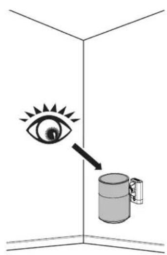
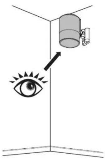
BELOW
Eye Level
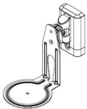
Installation
natural_image
Diagram showing an eye pointing to a cylindrical object with a handle, enclosed in a corner (no text or symbols)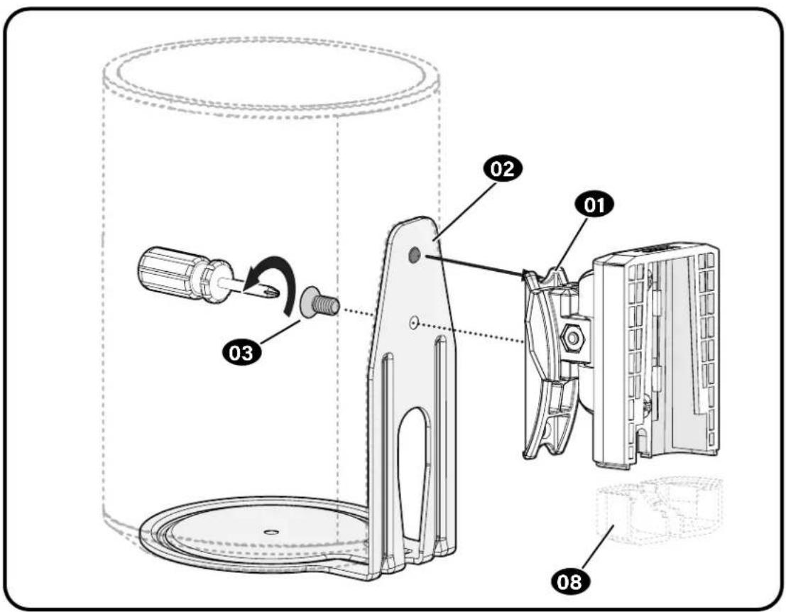
text_image
Technical diagram of a mechanical device with labeled parts including pin, screw, and housing componentsABOVE
Eye Level
Installation
(Speaker Upside Down)
text_image
Diagram showing a camera mounted on a wall-mounted device with an eye icon and directional arrow indicating light or perspective.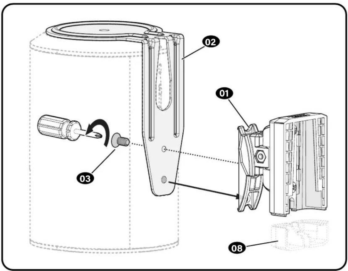
text_image
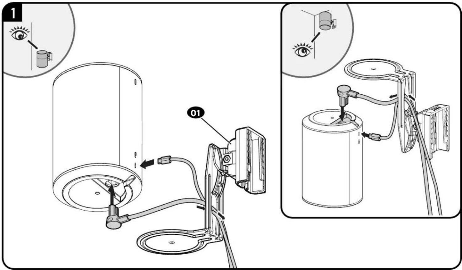
Technical diagram of a mechanical device with labeled parts and directional arrows indicating motion or assembly.STEP 2
Attach Speaker to Bracket
text_image
Technical diagram illustrating eye measurement setup with labeled components and instructions for eye alignment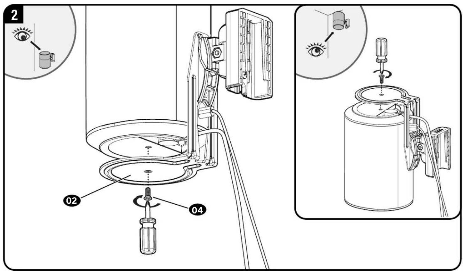
text_image
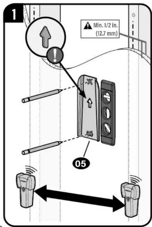
2 02 04STEP 3-A
Drywall Only InstallationAttach Wall PI
CAUTION: Avoid potential personal injury or property damage!
● Drywall covering the wall, must not be less than 1/2 in. (12.7 mm)
text_image
1 Min. 1/2 in. (12.7 mm) 05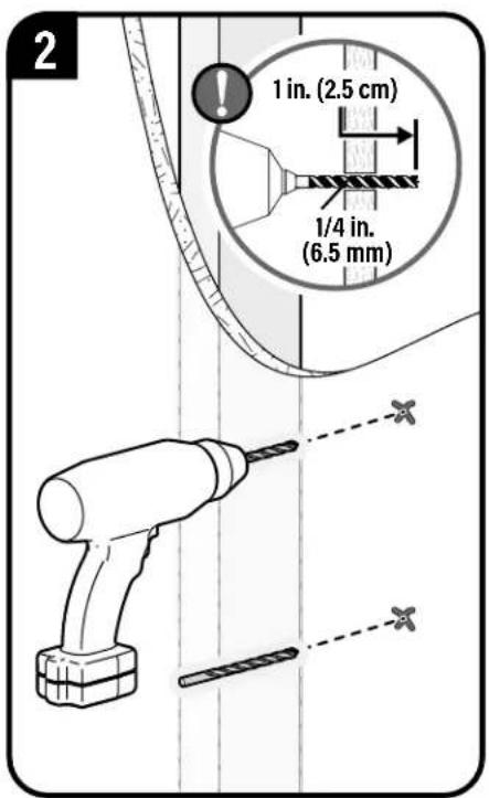
text_image
2 1 in. (2.5 cm) 1/4 in. (6.5 mm)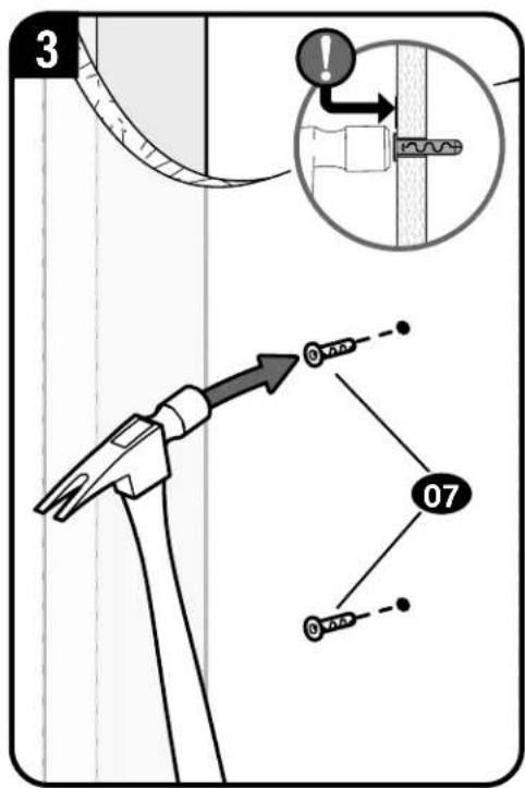
text_image
3 07 07CAUTION: Avoid potential personal injury or property damage!
DO NOT use power tools for this step.
Both screws 06 MUST BE firmly tightened to prevent unwanted movement of the wall plate 05. Ensure the wall plate is securely fastened to the wall before continuing on to the next step, but DO NOT overtighten the screws.
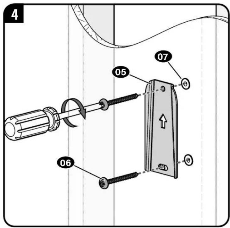
text_image
4 05 07 06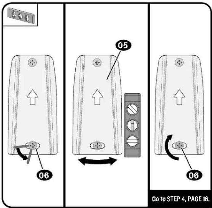
text_image
06 05 06 Go to STEP 4, PAGE 16.STEP 3-B
Wood Stud InstallationAttach Wall Plate t

CAUTION: Avoid potential personal injury or property damage!
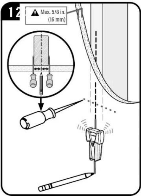
● Drywall covering the wall, must not exceed 5/8 in. (16 mm)
Minimum wood stud size: nominal 2 x 4 in. (51 x 102 mm) actual 1½ x 3½ in. (38 x 89 mm)
• Stud center must be verified
text_image
12 Max. 5/8 in. (16 mm)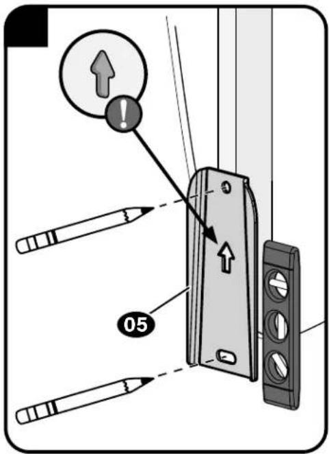
text_image
Diagram showing a device lock switch with labeled components and an alert icon, including pencil and pencil tip functions.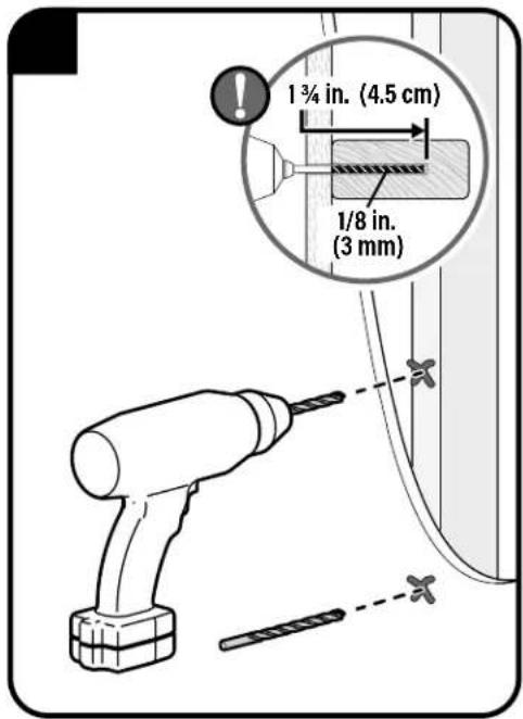
text_image
1¾ in. (4.5 cm) 1/8 in. (3 mm)CAUTION: Avoid potential personal injury or property damage!
DO NOT use power tools for this step.
Both screws 06 MUST BE firmly tightened to prevent unwanted movement of the wall plate 05. Ensure the wall plate is securely fastened to the wall before continuing on to the next step, but DO NOT overtighten the screws.
text_image
4 05 06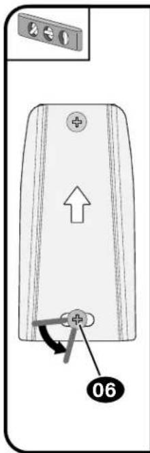
text_image
Diagram of a device rear panel with labeled components and directional arrow, marked as 06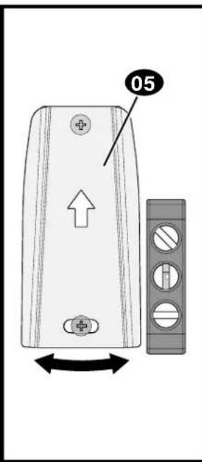
text_image
05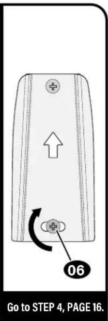
text_image
Go to STEP 4, PAGE 16.STEP 3-C
Attach Wall Plate to Wall
Solid Concrete or Concrete Block Installation

CAUTION: Avoid potential personal injury or property damage!
- Mount the wall plat 05 directly onto the concrete surface (no wall covering)
● Minimum solid concrete thickness: 8 in. (203 mm)
● Minimum concrete block size: 8 x 8 x 16 in. (203 x 203 x 406 mm)
text_image
1 05
text_image
2 2 in. (5 cm) 1/4 in. (6.5 mm)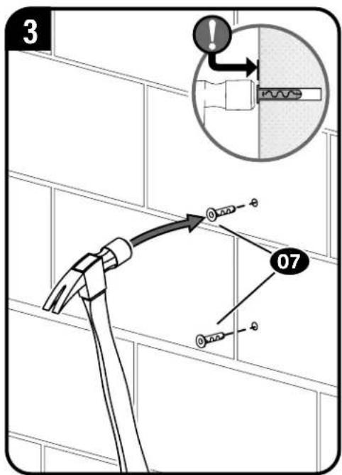
text_image
3 07CAUTION: Avoid potential personal injury or property damage!
DO NOT use power tools for this step.
Both screws 06 MUST BE firmly tightened to prevent unwanted movement of the wall plate 05. Ensure the wall plate is securely fastened to the wall before continuing on to the next step, but DO NOT overtighten the screws.
text_image
4 05 07 ⑧ 06 ⑨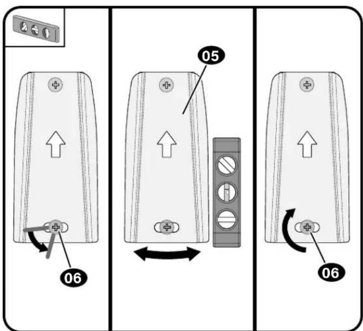
text_image
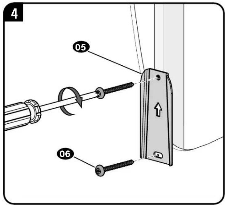
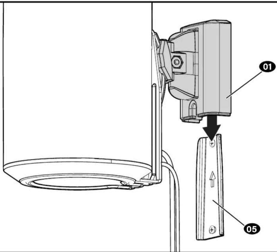
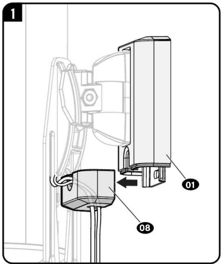
06 05 06STEP 4
Mount Assembly to Wall Plate
1
text_image
Technical diagram showing a device with labeled parts 01 and 05, indicating assembly or installation steps.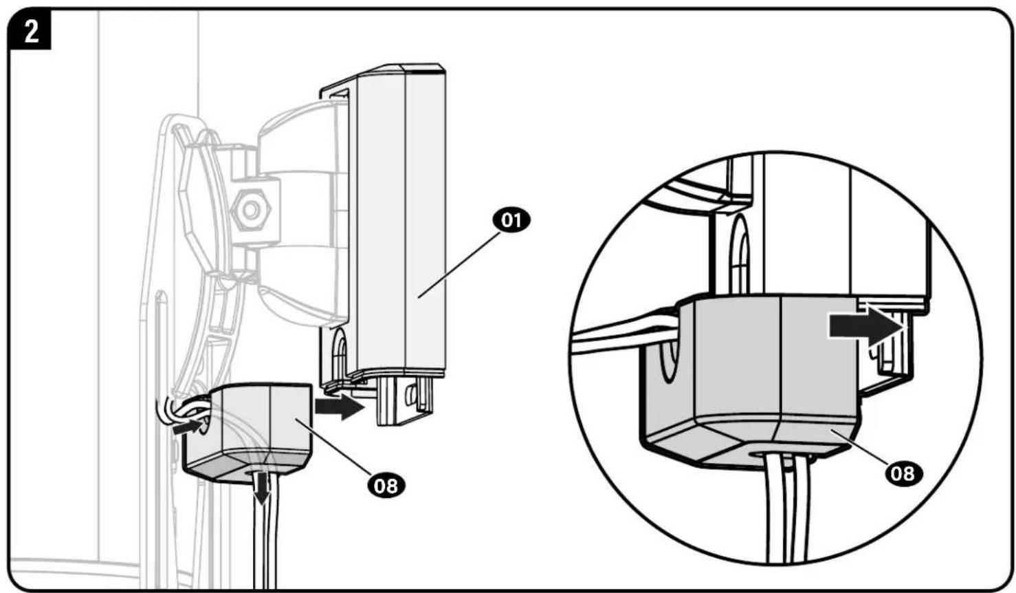
text_image
2 01 08 08Adjustments
text_image
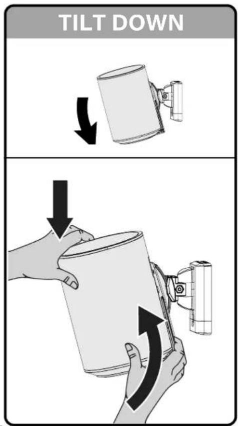
TILT DOWN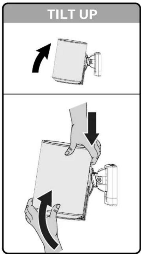
text_image
TILT UP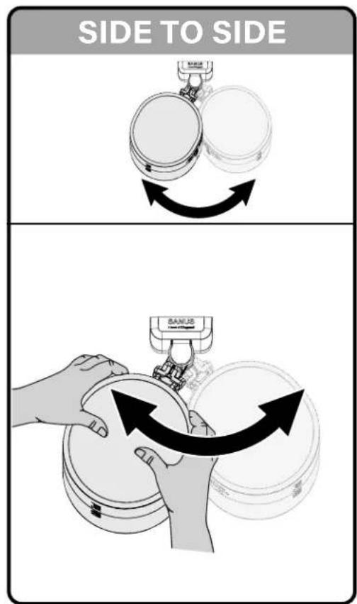
text_image
SIDE TO SIDE BANJIS Frost StabilizedTo Remove
text_image
1 01 08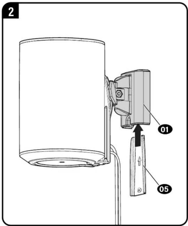
text_image
2 01 05ESPAÑOL
natural_image
Four different types of electrical tools: a pencil, a push-button switch, a screwdriver, and a variable resistor (no text or symbols present)铅笔 水平仪 螺丝刀 电钻
木墙柱安装

墙柱
查找器
尖钻 木钻头 石钻头
混凝土安装
(17) 100
壁板安装
壁板钻头

锤子
尺寸
第3页
中文
配套零件和配件
第4页
text_image
SANUS® A brand of □legrandThank you for choosing SANUS! Please take a moment to let us know how we did:
Legrand AV Inc.
6436 City West Parkway
Eden Prairie, MN 55344 USA
US: +1 (800) 359-5520
Legrand AV Netherlands B.V.
Franklinstraat 14
6003 DK Weert Netherlands
UK: +44 (0) 800 056 2853
EMEA: +31 (0) 495 580 852
Authorized Representative for the UK
Starline Holding Technology Ltd.
Unit C Island Road
Reading RG2 ORP UK
Legrand AV Inc. and its affiliated corporations and subsidiaries (collectively, "Legrand"), intend to make this manual accurate and complete. However, Legrand AV makes no claim that the information contained herein covers all details, conditions, or variations. Nor does it provide for every possible contingency in connection with the installation or use of this product. The information contained in this document is subject to change without notice or obligation of any kind. Legrand AV makes no representation of warranty, expressed or implied, regarding the information contained herein. Legrand AV assumes no responsibility for accuracy, completeness or sufficiency of the information contained in this document.
©2023 Legrand AV Inc. All rights reserved. SANUS is a brand of Legrand.
All other brand names or marks are used for identification purposes and are trademarks of their respective owners.
Legrand AV Inc. · 6436 City West Parkway · Eden Prairie, MN 55344 USA
6901-603142 00