MagicSafe MS 680 - Alarm system DOMETIC - Free user manual and instructions
Find the device manual for free MagicSafe MS 680 DOMETIC in PDF.

| Product type | Vehicle anti-theft alarm system |
| Brand | Dometic |
| Model | MagicSafe MS 680 |
| Operating voltage | 12 V |
| Supply voltage range | 9 – 15 V |
| Power consumption (active) | max. 800 mA |
| Power consumption (inactive) | approx. 10 mA |
| Remote control transmission frequency | 433.92 MHz |
| Remote control range | 10 – 20 m |
| Remote control battery type | CR2032, 3 V |
| Remote control dimensions (L x W x H) | 54 x 39 x 12 mm |
| Operating temperature (control unit) | -30 °C to +70 °C |
| Operating temperature (remote control) | -20 °C to +60 °C |
| Alarm duration | 30 s |
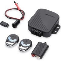
| Package contents | Control unit, siren, 2 ultrasonic detectors, radio remote control, ultrasonic module, electronic key with base, specific cable set with OBD connector, engine hood contact switch, bracket, fixing material, manual |
| Main functions | Activation/deactivation via original remote control, interior monitoring by ultrasound, programmable optical and acoustic signals, input for additional switches (hood, trunk), alarm memory |
| Care and cleaning | Clean with a damp cloth. Do not use aggressive detergents or hard objects. |
| Safety | Disconnect the battery before installation. Do not mount ultrasonic detectors in the deployment zone of an airbag. Secure all components firmly. |
| Spare parts and repairability | Available accessories: infrared motion detector, magnetic switch, additional electronic key and base. Have them installed by a specialist if necessary. |
| Warranty | Statutory. Contact the manufacturer or specialized dealer. |
Frequently Asked Questions - MagicSafe MS 680 DOMETIC
User questions about MagicSafe MS 680 DOMETIC
0 question about this device. Answer the ones you know or ask your own.
Ask a new question about this device
Download the instructions for your Alarm system in PDF format for free! Find your manual MagicSafe MS 680 - DOMETIC and take your electronic device back in hand. On this page are published all the documents necessary for the use of your device. MagicSafe MS 680 by DOMETIC.
USER MANUAL MagicSafe MS 680 DOMETIC
natural_image
Diagram of a connector with a cylindrical body and two separate plastic components, labeled with number 1 (no text or symbols on the diagram itself)
5

6
natural_image
Technical line drawing of a mechanical bracket with mounting holes and wiring (no text or symbols)
| EN: 11 | SV: 203 |
| DE: 34 | NO: 225 |
| FR: 60 | FI: 248 |
| ES: 85 | RU: 271 |
| PT: 109 | PL: 295 |
| IT: 133 | SK: 319 |
| NL: 157 | CS: 342 |
| DA: 181 | HU: 365 |
7
8
i
| EN | DE | FR | ES | PT | IT | NL | DA | |
| bl | Blue | Blau | Blou | Azul | Azul | Blu | Blauw | Bà |
| br | Brown | Braun | Marron | Marrón | Castanho | Marrone | Bruin | Brun |
| ge | Yellow | Gelb | Jaune | Amarillo | Amarelo | Giallo | Geel | Gul |
| gr | Grey | Grau | Gris | Gris | Cinzento | Grigio | Gijs | Gà |
| rt | Red | Rot | Rouge | Rojo | Vermelho | Rosso | Rood | Rod |
| sw | Black | Schwarz | Noir | Negro | Preto | Nero | Zwart | Sort |
| vt | Violet | Violett | Violeta | Lia | Violeta | Violetto | Paars | Violet |
| SV | NO | FI | RU | PL | SK | CS | HU | |
| ol | Blă | Blă | Sininen | Синий | Niebieski | Modrá | Modrá | Kék |
| br | Brun | Brun | Ruska | Коричновый | Brązowy | Hroda | Hnóda | Barna |
| ge | Gul | Gul | Keltainen | Жепный | Żółty | Żtá | Żlutá | Sárga |
| gr | Gră | Gră | Hamraa | Зеленый | Zelony | Zelená | Zelená | Szürke |
| rl | Röcl | Röcl | Pursinon | Красный | Czernworry | Ćorvená | Ćorvená | Piros |
| sw | Svart | Svart | Musta | Черный | Czamy | Ćierna | Ćerná | Fekete |
| vt | Violett | Fiolett | Violetti | Фионетовый | Fioletowy | Falová | Falová | Ibolya |
DOMETIC
SAFETY SOLUTIONS
ALARM SYSTEMS
natural_image
Technical line drawings of various electronic components including an inverter, cable, and sensors (no text or labels)MS680
EN Alarm system Installation and Operating Manual.....3
Please read this instruction manual carefully before installation and first use, and store it in a safe place. If you pass on the product to another person, hand over this instruction manual along with it.
Table of contents
1 Explanation of symbols....4
2 Safety and installation instructions ....4
3 Scope of delivery ....7
4 Accessories....7
5 Intended use ....7
6 Technical description ....8
7 Installing the alarm system 10
8 Connecting the alarm system electrically .....12
9 Programming the alarm system .....16
10 Using the alarm system 20
11 Care and cleaning. 23
12 Warranty 23
13 Disposal.... 24
14 Technical data 24
1 Explanation of symbols

WARNING!
Safety instruction: Failure to observe this instruction can cause fatal or serious injury.

CAUTION!
Safety instruction: Failure to observe this instruction can lead to injury.

NOTICE!
Failure to observe this instruction can cause material damage and impair the function of the product.

NOTE
Supplementary information for operating the product.
2 Safety and installation instructions
The manufacturer accepts no liability for damage in the following cases:
- Faulty assembly or connection
- Damage to the product resulting from mechanical influences and excess voltage
• Alterations to the product without express permission from the manufacturer - Use for purposes other than those described in the operating manual
Please observe the prescribed safety instructions and stipulations from the vehicle manufacturer and service workshops.

WARNING!
Inadequate supply cable connections could result in short circuits, which could have as a consequence that:
- Cable fires occur
• The airbag is triggered
• Electronic control devices are damaged
• Electric functions fail (indicators, brake light, horn, ignition, lights)

NOTICE!
To prevent the risk of short circuits, always disconnect the negative terminal of the vehicle's electrical system before working on it.
If the vehicle has an additional battery, its negative terminal should also be disconnected.
Please observe the following instructions:
- When working on the following cables, only use insulated cable lugs, plugs and flat push-on receptacles:
- 30 (direct supply from positive battery terminal)
- 15 (connected positive terminal, behind the battery)
- 31 (return line from the battery, earth)
- L (indicator lights left)
- R (indicator lights right)
Do not use terminal strips.
- Use a crimping tool to connect the cables.
- When connecting to cable 31 (earth), screw the cable
- to the vehicle's earth bolt with a cable lug and a gear disc or
- to the sheet-metal bodywork with a cable lug and a self-tapping screw.
Ensure that there is a good earth connection.
If you disconnect the negative terminal of the battery, all data stored in the volatile memories will be lost.
- The following data must be set again, depending on the vehicle equipment options:
- Radio code
- Vehicle clock
- Timer
- On-board computer
- Seat position
You can find instructions for making these settings in the appropriate operating instructions.
Observe the following installation instructions:

CAUTION!
- Secure the parts installed in the vehicle in such a way that they cannot become loose under any circumstances (sudden braking, accidents) and cause injuries to the occupants of the vehicle.
- Secure any parts of the system covered by the bodywork in such a manner that they cannot be come loose or damage other parts and cables or impair vehicle functions (steering, pedals, etc).
- Always follow the safety instructions of the vehicle manufacturer. Some work (e.g. on retention systems such as the AIRBAG etc.) may only be performed by qualified specialists.

NOTICE!
- To prevent damage when drilling, make sure there is sufficient space on the other side for the drill head to come out.
- Deburr all drill holes and treat them with a rust-protection agent.
Observe the following instructions when working with electrical parts:

NOTICE!
- When testing the voltage in electrical cables, only use a diode test lamp or a voltmeter. Test lamps with an illuminant take up voltages which are too high and which can damage the vehicle's electronic system.
- When making electrical connections, ensure that: - they are not kinked or twisted - they do not rub on edges - they are not laid in sharp edged ducts without protection.
- Insulate all connections. - Secure the cables against mechanical wear with cable binders or insulating tape, for example to existing cables.
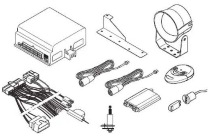
3 S c o p e o f d
See fig. 1
No. Quantity Description Ref. no.
| 1 1 Control unit 9101600015 | |
| 2 1 Siren MS-670-SI | |
| 3 2 Ultrasonic sensors | |
| 4 1 Radio remote control 9101600016 | |
| 5 1 Ultrasonic module (including sensors) | MS-670-US |
| 6 1 Electronic key (e-key) with base | |
| 7 1 Vehicle-specific cable set with OBD plug | |
| 8 1 Bonnet contact switch | |
| 9 1 Holder for bonnet contact switch and siren | |
| – | – Fastening and installation material |
| – | – Installation and operating manual |
4 A c c e s s o r i
Available as accessories (not included in the scope of delivery):
| Description | Ref. no. |
| Wireless infrared motion sensor | 9101600013 |
| Wireless magnetic contact switch | 9101600014 |
| Electronic key | MS-670-EK |
| Electronic key base | MS-670-ES |
5 Intended use
MS680 (ref. no. 9101600012) is an alarm system and preset for a Fiat Ducato x290 (manufactured in 2015). Optionally, the alarm system can also be used for a Fiat Ducato x250 (manufactured in 2011). For the connection data for a Fiat Ducato x250, refer to chapter "Connection data for Fiat Ducato x250 (without connection to the central locking system)" on page 15.
The alarm system offers additional protection against the theft of your vehicle and its contents.
6 Technical description
6.1 Function description
MS680 is an alarm system with two ultrasonic sensors and a siren. The alarm system can optionally be extended by up to 55 wireless infrared motion detectors and wireless magnetic contact switches. It is designed for vehicles with a voltage of 12 V and is enabled or disabled when operating the original vehicle remote controls.
When the alarm system is activated, an alarm is triggered when one of the following events occurs:
- A door opens.
- The boot is opened.
• The bonnet is opened.
• The ignition is turned on. - An (optional) wireless sensor (radio magnetic contact, wireless motion) reports movement.
The product offers you the following features:
- Activation and deactivation with original vehicle remote control
- Programmable acoustic and optical signals
• Interior monitoring of the passenger compartment using ultrasonic sensors
• Additional remote control to deactivate the interior monitoring
• E-key (electronic key) for programming and deactivating the alarm system - Input for the connection of additional door contacts or a contact switch for the bonnet or the boot.
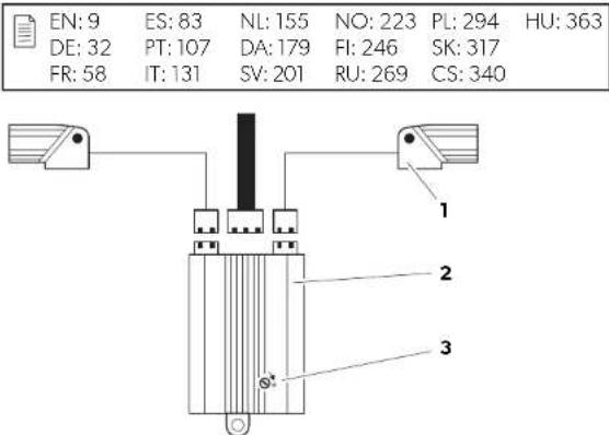
6.2 Control unit
See fig. 2
No. Description
1 Connection plug
2 Connection plug for 20-pin connection cable
3 Button (for programming)
4 LED
6.3 Radio remote control
See fig. 3
No. Description
1 Deactivates the entire system (including unlocking of the doors upon connection of the central locking system, see chapter "Optional connection options" on page 14)
2 Deactivates the interior monitoring system with an activated system or activates the system without the interior monitoring (including interlock of doors upon connection of the central locking system, see chapter "Optional connection options" on page 14)
3 Activates the complete system (including interior monitoring and interlock of the doors upon connection of the central locking system, see chapter "Optional connection options" on page 14)
6.4 Ultrasonic module
See fig. 5
No. Description
1 Ultrasonic sensors
2 Ultrasonic module
3 Adjusting screw
6.5 Possible operating states
The alarm system has the following operating modes:
- Stand-by
The alarm system is constantly on stand-by as soon as it is installed and correctly connected. However, it does not trigger the alarm when in stand-by.
- Activation time
The alarm system has an activation time of approx. 40 seconds.
As an optical indicator of the activation time, the LED is illuminated on the electronic key base (fig. 41).
- Activated
If the alarm system is activated, it can trigger an alarm. This happens if someone breaks into the door, opens the bonnet or enters the vehicle interior. If you wish to drive off, you must first deactivate the alarm system. The system is then in stand-by mode.
As an optical indicator for activation, the LED flashes on the electronic key base (fig. 41).
- Alarm triggered
When an alarm has been triggered, it is indicated by optical and acoustic signals.
7 Installing the alarm system

NOTE
If you do not have sufficient technical knowledge for installing and connecting the components in vehicles, you should have a specialist install the alarm system in your vehicle.
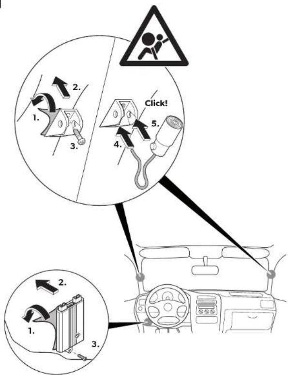
7.1 Installing the controller
▶Select a suitable installation location.
▶ Install the control unit
– In the vehicle interior
- In such a way that you can read the LED and operate the button
- Under the dashboard
- Not in areas where strong electrical fields could cause interference, e.g. ignition cables or central control electronics
- Not directly next to ventilator nozzles.
▶Screw the control unit firmly to the vehicle with the screws supplied or use double-sided adhesive tape.
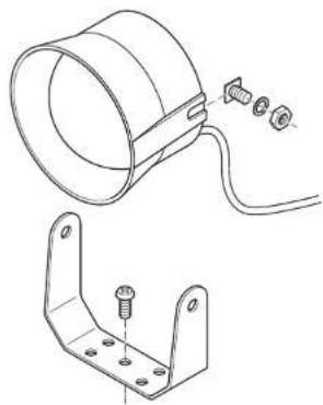
7.2 Mounting the siren
See fig. 6
The siren can be mounted in the engine compartment.

NOTICE!
When mounting it, ensure that the installation location is
- Not in an area exposed to splashing water
- Not near the exhaust system
- Not accessible from underneath the vehicle, to ensure that it cannot be tampered with.
▶ Install the siren and the holder as shown in fig. 6.
7.3 Installing the ultrasonic module
See fig. 5
▶ Install the ultrasonic module as illustrated in fig. 5.
7.4 Installing the ultrasonic sensors
See fig. 7

CAUTION!
Risk of injury if the airbag deploys!
Do not fit the ultrasonic sensors where an airbag may open.
▶Align the ultrasonic sensors so that they point towards the centre between the backrests of the front seats (of the passenger compartment).
▶ Lay the connecting cables of the sensors through the A-pillar to the ultrasonic module.
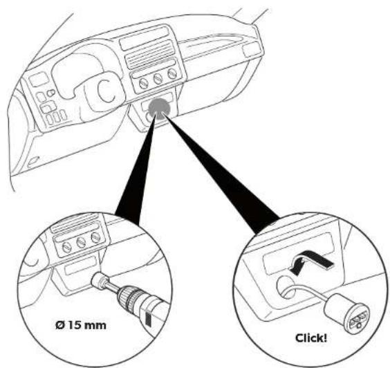
7.5 Installing the bonnet contact switch
▶ Find a suitable location in the engine compartment and drill a hole with a diameter of 8 mm.
▶ During installation make sure the distance to the closed bonnet is between 22 mm and 27 mm.
Use putty, for example, to check this distance.
You can further reduce the minimum distance by shortening the switch.
▶Test the switch function after installation.
▶ Connect the bonnet contact switch with the grey wire (fig. 9) of the connection cable of the siren in the engine compartment.
7.6 Mounting the base for the electronic key
See fig. 8

NOTE
When selecting the installation location, pay attention to the cable lengths and whether the LED in the base is to be visible.
8 Connecting the alarm system electrically
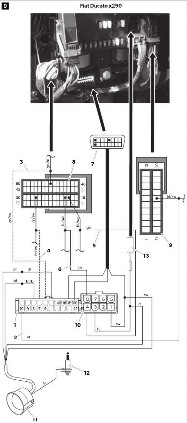
Fiat Ducato x290: You can find the circuit diagram in fig. 9.
No. Description
| 1 20-pin plug of the connection cable on the MS680 control unit | ||||||
| 2 Connected positive terminal (ignition, terminal 15) | ||||||
| 3 Central locking system | ||||||
| 4 Central locking system | ||||||
| 5 Right-hand indicator | ||||||
| 6 Left-hand indicator | ||||||
| 7 | O | B | D | p | l | u |
| 8 60-pin green plug from the vehicle fuse box | ||||||
| 9 20-pin black plug from the vehicle fuse box | ||||||
| No. Description | ||||||
| 10 8-pin plug of the connection cable on the MS680 control unit | ||||||
| 11 Siren | ||||||
| 12 Bonnet switch | ||||||
| 13 Power supply connection | ||||||
All plugs are coded so that you cannot connect them incorrectly.
8.1 Connecting the connection wires of the connection cable (fig. 9)
Connecting the siren
▶ Insert the plug of the connection cable (fig. 9 11) into the connection of the ultrasonic module.
▶ Guide this open cable end through the splash-protection wall into the passenger compartment.
▶ Connect the red cable of the siren to the red cable of PIN 3 (8-pin plug of the connection cable on the MS680 control unit) (fig. 9 10).
▶ Connect the blue cable of the siren to the blue/brown cable of PIN 18 (20-pin plug of the connection cable on the MS680 control unit) (fig. 9 1).
▶ Connect the grey cable to the grey cable of PIN 15 (20-pin plug of the connection cable on the MS680 control unit) (fig. 9 1).
▶ Connect the black cable to the black cable of PIN 1 (8-pin plug of the connection cable on the MS680 control unit) (fig. 9 10).
Connecting the electronic key base
▶ Plug the red two-pin connector of the electronic key base (fig. 1 6) into the red socket of the connection cable.
▶ Plug the white two-pin connector of the electronic key base (fig. 1 6) into the white socket of the connection cable.
Violet (ignition plus)
▶ Connect the violet cable of PIN 10 (20-pin plug of the connection cable) (fig. 9 1) to PIN 16 (20-pin black plug of the vehicle fuse box) (fig. 9 9).
Connecting the ultrasonic module (fig. 5 2)
Insert the white 3-pin plug of the connection cable into the connection of the ultrasonic module.
Connecting the ultrasonic sensors (fig. 51)
▶ Insert the red plug of the ultrasonic sensor cable into the red connection of the ultrasonic module (fig. 9 5).
▶ Insert the red plug of the ultrasonic sensor cable in the white connection of the ultrasonic sensor (fig. 9 5).
Yellow (indicator)
▶ Connect the yellow cable of PIN 4 (8-pin plug of the connection cable on the MS680 control unit) (fig. 9 10) to PIN 18 of the right indicator cable (60-pin green plug of the vehicle fuse box) (fig. 9 8).
Connect the yellow cable of PIN 8 (8-pin plug of the connection cable on the MS680 control unit) (fig. 9 10) to PIN 19 of the left indicator cable (60-pin green plug of the vehicle fuse box) (fig. 9 8).
8.2 Optional connection options
Brown/black (central locking system)
Connect the brown/black cable of PIN 17 (20-pin plug of the connection cable) (fig. 9 1) to PIN 27 (60-pin green plug from the vehicle fuse box) (fig. 9 8), if you would like to also open and lock the vehicle with the additional hand-held transmitter as well as activate and deactivate the MS680.
Grey/black (central locking system)
Connect the grey/black cable of PIN 16 (20-pin plug of the connection cable) (fig. 9 1) to PIN 53 (60-pin green plug from the vehicle fuse box) (fig. 9 8), if you would like to also open and lock the vehicle with the additional hand-held transmitter as well as activate and deactivate the MS680.
Connection data for Fiat Ducato x250 (without connection to the central locking system)
Yellow - indicator (standard)
▶ Connect the yellow cable of PIN 4 (8-pin plug of the connection cable on the MS680 control unit) (fig. 9 10) to PIN 18 (blue/black cable) of the right indicator cable (60-pin green/blue plug of the vehicle fuse box).
▶ Connect the yellow cable of PIN 8 (8-pin plug of the connection cable on the MS680 control unit) (fig. 9 10) to PIN 19 (blue/white cable) of the left indicator cable (60-pin green/blue plug of the vehicle fuse box).
Violet - ignition (+15)
▶ Connect the violet cable of PIN 10 (20-pin plug of the MS 680 connection cable) (fig. 9 1) to PIN 18 (light blue/grey) (20-pin black/blue plug of the vehicle fuse box).
8.3 Connecting the connection cable
▶ Insert the 20-pin plug and the 8-pin plug of the connection cable into the appropriate connection on the control unit of the alarm system (fig. 9 1 and fig. 9 10).
▶ Insert the OBD plug (fig. 9 7) into the OBD connection underneath the vehicle fuse box.
Red
▶ Insert the cable lug (fig. 9 13) of the red cable of PIN 3 of the 8-pin plug of the connection cable into the MS680 control unit (fig. 9 10) in the open slot of the vehicle fuse box (fig. 9).
9 Programming the alarm system

NOTE
The alarm system is pre-programmed for the Fiat Ducato x290.
9.1 Programming the vehicle code
The alarm system must be adjusted to the CAN bus of your vehicle type. The alarm system is factory set to the vehicle code 131 for Fiat Ducato x250 and Fiat Ducato x290.
If you need to reprogram the vehicle code, proceed as follows:
▶ Press the button (fig. 2 3) on the control unit and hold it down.
▶ When the LED on the control device (fig. 2 4) lights up, release the button.
√The LED goes out.
√ After a pause of 4 seconds, the LED begins to flash.
▶ Count the number of flashes until the number agrees with the first number of your vehicle code:
- One flash: Number 1
- T w o f l a s h e s : N u m b e r 2 , ...
– Nine flashes: Number 9
– Ten flashes: Number 0
▶Press the button again.
√ After a pause of 4 seconds, the LED begins to flash.
▶ Repeat the steps described above for all the digits of the vehicle code.
√ After programming, the LED flashes the vehicle code.
▶ Test the alarm system by activating it with your remote control.
√ When you correctly enter the vehicle code, the alarm system will be activated.
If the alarm system is not activated, you have not entered the vehicle code correctly. Repeat the programming.
9.2 Programming (optional)
You can program the functions listed in the following table. These functions remain stored even if the battery is disconnected.
To program a function, proceed as follows:
▶ Start the ignition with the alarm system deactivated.
√The LED in the base of the electronic key illuminates for two seconds.
▶ Insert the electronic key into the key holder within these two seconds.
√ To indicate that the programming mode has been activated, the LED flashes three times and the siren emits three acoustic signals.
√The first function is activated.

NOTE
Each time you call up the programming mode in this way, all the values of the individual functions are reset to the factory settings (see following table).
| Function | Factory setting | LED Programming |
| Optical signals during activation/deactivation | Off Flashes once This function can only be activated for vehicles which do not emit any optical signals (e.g. indicator) during opening or closing. | |
| Acoustic signals Off Flashes twice The following acoustic signals are emitted:Activating: 2 signalsDeactivating: 1 long signalDeactivating when the alarm has been triggered: 1 brief signal | ||
| Passive alarm Off Flashes three times | This function automatically activates the alarm system 60 seconds after the ignition has been switched off.When this function is activated, the convenience output and the ultrasonic sensors are deactivated. | |
| Function | Factory setting | LED Programming | |
| Door contact input | Negative Flashes four times | The factory setting switches the convenience output to negative so that an external system can be connected. | |
| Flashes five times | Do not change the value! | ||
| Flashes six times | Do not change the value! | ||
Modifying selected function
▶ Insert the electronic key in the electronic key base in order to modify the value of the selected function.
√If the factory setting is "On", the value is set to "Off" and vice versa.
√ The siren emits an acoustic signal, and the LED on the electronic key base flashes once.
Activating the next function
▶Switch the ignition off and on again.
√The next function is activated.
▶Modify the value as described above or switch the ignition off and on again to activate the next function.
▶ Once you have called up all functions in sequence, switch the ignition off and on again to confirm the entered values.
√The alarm system indicates the leaving of the programming mode and the storing of the entered values by having the LED on the electronic key base flash three times and the siren emit three acoustic signals.
9.3 Programming new electronic keys and new wireless contacts
The alarm system can be used with up to 55 sensors (electronic keys, wireless movement sensors, wireless magnetic contact switches).

NOTE
To program new sensors, the bonnet must be open (grey cable to earth).
Proceed as follows to program a new sensor:
▶Deactivate the alarm.
▶Switch the ignition on and off.
▶Switch the ignition on and off again two more times within 4 seconds.
▶Switch on the ignition and leave it on.
√ The siren emits three acoustic signals, and the LED in the base of the electronic key flashes three times (fig. 41).
▶ Insert the new electronic key in the key holder. Alternatively, press the program button on the wireless sensor (see the operating manual of the wireless sensor).
√The sensor is automatically programmed.
√ The LED flashes once when the programming operation is completed.
▶ Repeat the programming steps for each new sensor to be programmed.
▶Switch the ignition off to exit the programming function.
√ The siren emits three acoustic signals and the LED flashes three times.
9.4 Removing programmed devices
▶Deactivate the alarm.
▶Switch the ignition on and off.
▶Switch the ignition on and off again two more times within 4 seconds.
▶Switch on the ignition and leave it on.
√ The siren emits three acoustic signals, and the LED in the base of the electronic key flashes three times. The LED then lights up continuously (fig. 4 1).
▶Remove the grey cable from earth (e.g. bonnet closed).
▶Wait 8 seconds to remove all programmed devices.
√Once all programmed devices have been removed, the LED turns off.
▶Switch the ignition off.
√ The siren emits three acoustic signals, and the LED in the base of the electronic key flashes three times.
10 Using the alarm system
10.1 Activating the alarm system
To activate the alarm system manually, proceed as follows:
▶Lock the vehicle with your remote control.
√ The vehicle emits optical signals according to the factory settings.

NOTE
After roughly 40 seconds, the alarm system indicates that it is ready to operate with flashing of the LED in the base of the electronic key.
Activating the alarm system so that the vehicle can remain occupied
You can set the alarm system so that the alarm system does not trigger an alarm – to spend the night in the vehicle, for example.
To do this, follow the steps below under A or B:
A) Cables for the central locking system are connected (fig. 9 3 and fig. 9 4):
▶ Press button (fig. 3 2) on the additional remote control.
√ The vehicle locks and the alarm system is activated with deactivated interior monitoring. (The wireless magnetic contact switches remain active.)
B) Cables for the central locking system are not connected (fig. 9 3 and fig. 9 4):
▶Lock the vehicle with the original vehicle remote control.
√The vehicle is locked and the alarm system activated.
▶ Press button (fig. 3 2) on the additional remote control within 30 seconds.
√ The alarm system deactivates the interior monitoring. (The wireless magnetic contact switches remain active.)
10.2 Deactivating the alarm system
To deactivate the alarm system manually, proceed as follows:
▶Open the vehicle with your remote control.
√ The vehicle emits optical signals according to the factory settings.

NOTE
If an alarm was triggered, the siren emits a brief acoustic signal (see chapter "Sorting the alarm memory" on page 21).
Sorting the alarm memory
The alarm system stores triggered alarms. If you hear a short acoustic signal during deactivation, the alarm system has stored an alarm. You can read the alarm memory and determine the reason for the alarm.
To do this, proceed as follows:
▶ Switch on the ignition and observe the LED on the base of the electronic key (fig. 41).
√The LED shows the reason for the alarm:
| LED display Reason for alarm | Duration of display | |
| 2 x On - 2 s Off - 2 x On Ignition key was activated Ten times | ||
| 3 x On - 2 s Off - 3 x On Doors opened Ten times | ||
| 4 x On - 2 s Off - 4 x On Bonnet opened Ten times | ||
| 6 x On - 2 s Off - 6 x On Ultrasonic module Ten times | ||
| 8 x On - 2 s Off - 8 x On Wireless magnetic contact switch | Ten times | |
| 9 x On - 2 s Off - 9 x On | Wireless infrared motion sensor | Ten times |
▶ Switch off the ignition when you want to end the display.
Deactivate the alarm system with the electronic key (emergency deactivation / workshop mode)
In an emergency, you can deactivate the alarm system or put it into workshop mode using the electronic key. This means the alarm system will no longer be activated by the remote control and will remain completely switched off. Deactivation with the electronic key is possible only if the alarm system was activated for at least 40 seconds (the LED on the base of the electronic key flashes).
▶Open the vehicle door with the vehicle key.
√The alarm system triggers an alarm.
▶Insert the electronic key in the electronic key base.
√The alarm is deactivated and in "workshop mode".
The LED flashes every 16 seconds.
▶In order to restore the normal function, you must insert the electronic key into the key holder within 40 seconds after locking with the remote control.
√The alarm system can once again be activated and deactivated by your remote control.
10.3 Setting the sensitivity of the ultrasonic sensors (fig. 5)
The sensitivity of the ultrasonic sensors is set on the ultrasonic module.
▶ Turn the setting screw (fig. 5 3) on the underside of the ultrasonic module in the direction of “+” to increase the sensitivity or
▶ ... turn the setting screw of the ultrasonic module in the opposite direction “−” to reduce the sensitivity.
▶To deactivate the ultrasonic module, turn the setting screw of the ultrasonic sensor all the way in the direction “−”.

NOTE
If the ultrasonic sensors are set too sensitively, the alarm may be triggered by a hailstorm, for example. For this reason you should not set the sensitivity too high.
To find the right setting, proceed as follows:
▶Deactivate the alarm system (see chapter "Deactivating the alarm system" on page 21).
▶Open the front side window about 20 cm.
▶ Activate the alarm system with the doors, bonnet and boot closed.
▶Move an object into the vehicle interior from outside:
- If an alarm is triggered before you move the object into the vehicle, reduce the sensitivity.
- If no alarm is triggered, increase the sensitivity.
11 Care and cleaning

NOTICE!
Do not use sharp or hard objects or cleaning agents for cleaning as these may damage the product.
▶Occasionally clean the product with a damp cloth.
12 Warranty
The statutory warranty period applies. If the product is defective, please contact the manufacturer's branch in your country (see the back of the instruction manual for the addresses) or your retailer.
For repair and guarantee processing, please send the following items:
- Defect components
• A copy of the receipt with purchasing date - A reason for the claim or description of the fault
13 Disposal
▶ Place the packaging material in the appropriate recycling waste bins wherever possible.
If you wish to finally dispose of the product, ask your local recycling centre or specialist dealer for details about how to do this in accordance with the applicable disposal regulations.
14 Technical data
| MagicSafe MS680 | ||
| Ref. no.: 9101600012 | ||
| Operating voltage: 12 V--- | ||
| Input voltage: 9 – 15 V--- | ||
| Current: Max. 800 mA (activated) | Approx. 10 mA (deactivated) for 12 V--- | |
| Output current for indicator signals: 8 A at 20 °C | ||
| Output current for engine block: 8 A at 20 °C | ||
| Output current for siren: 5 A | ||
| Alarm duration: 30 s | ||
| Operating temperature: -30 °C to 70 °C | ||
| Approval for control unit: |  | |
| Hand-held transmitter | ||
| Transmission frequency: 433.92 MHz | ||
| Range: 10 – 20 m | ||
| Battery type: CR2032, 3 V | ||
| Operating temperature: -20 °C to 60 °C | ||
| Dimensions (L x W x H): | 54 x 39 x 12 mm | |
| Approval: |  | CEZugelassen in:For use in:B, CH, D, DK, E, F, GB,GR, I, IRL, L, NL, P |
6 Description technique
Dometic Australia Pty. Ltd.
1 John Duncan Court
Varsity Lakes QLD 4227
1800 212121
+61 7 55076001
Mail: sales@dometic.com.au
AUSTRIA
Dometic Austria GmbH
Neudorferstraße 108
A-2353 Guntramsdorf
+43 2236 908070
+43 2236 90807060
Mail: info@dometic.at
BENELUX
Dometic Branch Office Belgium
Zincstraat 3
B-1500 Halle
+32 2 3598040
+32 2 3598050
Mail: info@dometic.be
BRAZIL
Dometic DO Brasil LTDA
Avenida Paulista 1754, conj. 111
SP 01310-920 Sao Paulo
+551132513352
+551132513362
Dometic Group Asia Pacific
Suites 2207-11 · 22/F · Tower 1
The Gateway · 25 Canton Road,
Tsim Sha Tsui · Kowloon
+852 2 4611386
+852 2 4665553
Mail: info@waeco.com.hk
HUNGARY
Dometic Zrt. Sales Office
Kerékgyártó u. 5.
H-1147 Budapest
+3614684400
+3614684401
Dometic Italy S.r.l.
Via Virgilio, 3
I-47122 Forlì (FC)
+39 0543 754901
+39 0543 754983
Mail: vendite@dometic.it
JAPAN
Dometic KK
Maekawa-Shibaura, Bldg. 2
2-13-9 Shibaura Minato-ku
Tokyo 108-0023
+81 3 5445 3333
+81354453339
Mail: info@dometic.jp
MEXICO
Circuito Médicos No. 6 Local 1
Colonia Ciudad Satélite
CP 53100 Naucalpan de Juárez
Estado de México
+52 55 5374 4108
+52 55 5393 4683
Mail: info@dometic.com.mx
NETHERLANDS
Dometic Benelux B.V.
Ecustraat 3
NL-4879 NP Etten-Leur
+31 76 5029000
+31 76 5029019
Mail: info@dometic.nl
NEW ZEALAND
Dometic New Zealand Ltd.
Unite E, The Gate
373 Neilson Street
Penrose 1, Auckland
+6496221490
+6496221573
Mail: customerservices@dometic.co.nz
NORWAY
Dometic Norway AS
∅sterøyveien 46
N-3232 Sandefjord
+47 33428450
+47 33428459
Mail: firmapost@dometic.no
POLAND
Dometic Poland Sp. z o.o.
Ul. Puławska 435A
PL-02-801 Warszawa
+48 22 414 3200
+48 22 414 3201
Mail: info@dometic.pl
PORTUGAL
Dometic Spain, S.L.
Komsomolskaya square 6-1
RU-107140 Moscow
+7 495 780 79 39
+7 495 916 56 53
Mail: info@dometic.ru
SINGAPORE
Dometic Pte Ltd
18 Boon Lay Way 06-140 Trade Hub 21
Singapore 609966
+65 6795 3177
+65 6862 6620
Mail: dometic@dometic.com.sg
SLOVAKIA
Dometic Slovakia s.r.o. Sales Office Bratislava
Nádražná 34/A
900 28 Ivánka pri Dunaji
/ +421 2 45 529 680
Mail: bratislava@dometic.com
SOUTH AFRICA
Dometic (Pty) Ltd.
Regional Office
South Africa & Sub-Saharan Africa
2 Avalon Road
West Lake View Ext 11
Modderfontein 1645
Johannesburg
+27114504978
+27114504976
Mail: info@dometic.co.za
SPAIN
Dometic Spain S.L.
Avda. Sierra del Guadarrama, 16
E-28691 Villanueva de la Cañada
Madrid
+34 902 111 042
+34 900 100 245
Mail: info@dometic.es
SWEDEN
Dometic Scandinavia AB
Gustaf Melins gata 7
Dometic Switzerland AG
Riedackerstrasse 7a
CH-8153 Rümlang
+41 44 8187171
+41 44 8187191
Mail: info@dometic.ch
UNITED ARAB EMIRATES
Dometic Middle East FZCO
P.O.Box17860
S-D 6, Jebel Ali Freezone
Dubai
+97148833858
+97148833868
Mail: info@dometic.ae
UNITED KINGDOM
Dometic UK Ltd.
Dometic House, The Brewery
Blandford St. Mary
Dorset DT11 9LS
+44 344 626 0133
+44 344 626 0143
Mail: customerservices@dometic.co.uk
USA
Dometic RV Division
1120 North Main Street
Elkhart, IN 46515
+1574-264-2131