MagicSafe MS 660 - Alarm system DOMETIC - Free user manual and instructions
Find the device manual for free MagicSafe MS 660 DOMETIC in PDF.

| Product type | Anti-theft alarm system for vehicles (cars, motorhomes) |
| Operating voltage | 12 V (9-15 V) |
| Power consumption (activated) | < 20 mA |
| Power consumption (deactivated) | < 7 mA |
| Operating temperature | -40 °C to +85 °C |
| Control unit dimensions | 105 x 100 x 25 mm |
| Transmitter frequency | 433.992 MHz |
| Transmitter range | Up to 20 m |
| Transmitter battery type | CR2032, 3 V |
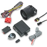
| Package contents | Control unit, 2 manual transmitters, electronic key, key holder with LED, hood switch, 2 ultrasonic detectors, ultrasonic module, connection cable, warning labels, mounting hardware |
| Main functions | Activation/deactivation via transmitter or electronic key or PIN code; interior surveillance via ultrasonic; inputs for door, hood, trunk switches; programmable comfort output; connection for additional siren; wireless learning of up to 15 radio detectors; garage mode; panic mode; central locking |
| Maintenance and cleaning | Clean with a damp cloth; do not use aggressive products or sharp objects |
| Safety instructions | Disconnect the battery before any intervention; use insulated terminals and connectors; do not use wire nuts; follow the vehicle manufacturer's instructions |
| Certifications | e1 and R&TTE |
Frequently Asked Questions - MagicSafe MS 660 DOMETIC
User questions about MagicSafe MS 660 DOMETIC
0 question about this device. Answer the ones you know or ask your own.
Ask a new question about this device
Download the instructions for your Alarm system in PDF format for free! Find your manual MagicSafe MS 660 - DOMETIC and take your electronic device back in hand. On this page are published all the documents necessary for the use of your device. MagicSafe MS 660 by DOMETIC.
USER MANUAL MagicSafe MS 660 DOMETIC
natural_image
Product photo of a black electronic device with attached earbuds and cable, no visible text or symbolsMS660
EN
Alarm system
Installation and Operating Manual.....14
DE
Alarmanlage
natural_image
Technical diagram showing a mechanical assembly with intersecting lines and arrows indicating motion (no text or symbols)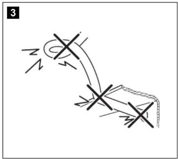
natural_image
Simple line drawing of a mechanical or electrical component with no text, numbers, or symbols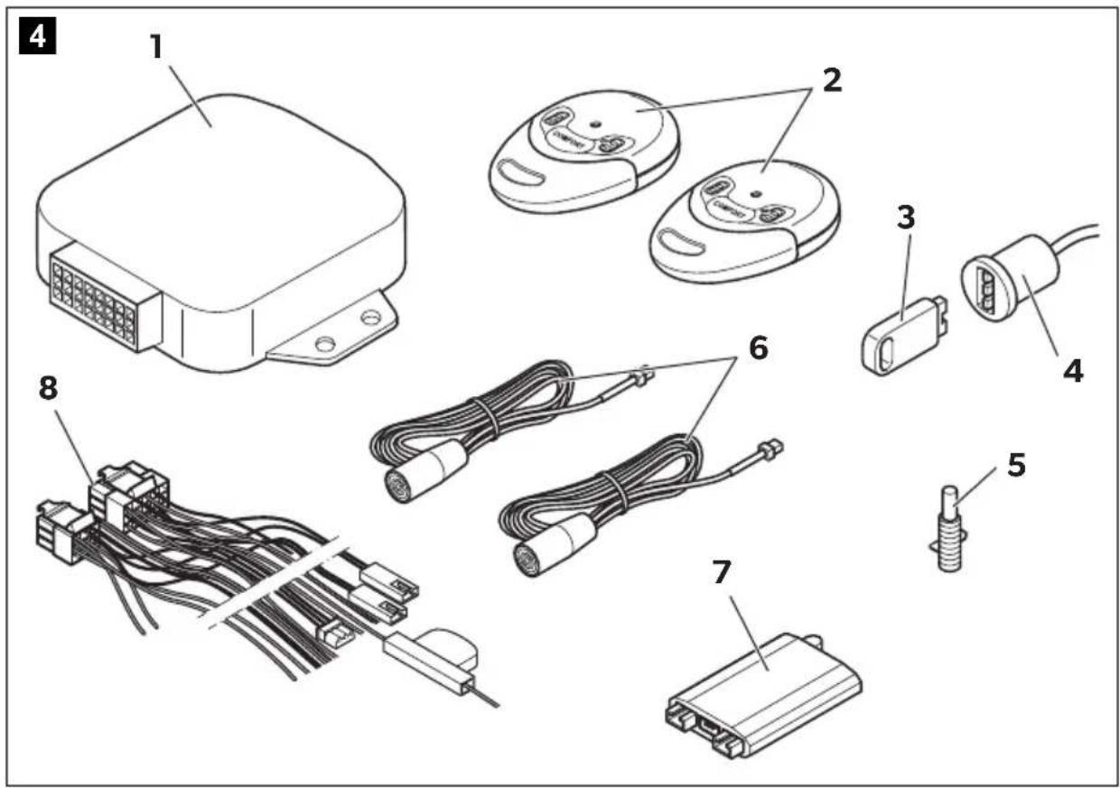
natural_image
Line drawing of a car dashboard with control panels and steering wheel (no text or symbols)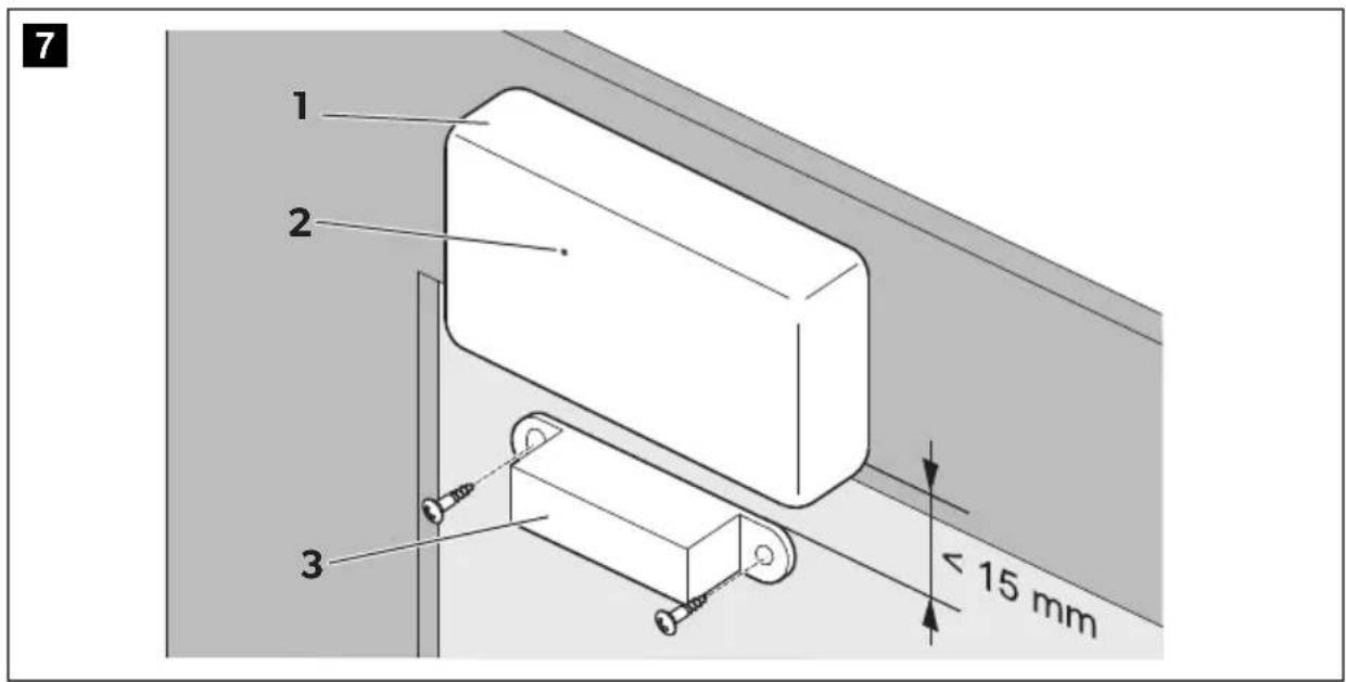
9
natural_image
Technical line drawing of two wall-mounted home appliances, one with screws and a side panel, the other with a door handle (no text or symbols)10

EN: 27
DA: 209
DE: 71
SV: 251
FR: 118
NO: 294
NL: 164
Fl: 337
A
B
11
12

EN: 28
DA: 209
DE: 71
SV: 252
FR: 118
NO: 295
NL: 164
Fl: 338
13

EN: 28
DA: 209
DE: 71
SV: 252
FR: 118
NO: 295
NL: 164
Fl: 338
14
15
16
17
18
19
20
21
| bl ge gr gn or rt sw ws n. c. | |||||||||
| EN | Blue Yellow Grey Green Orange Red Black White | Not Connected | |||||||
| DE | Blau | Gelb | Grau | Grün | Orange | Rot | Schwarz | Weiss | Nicht Belegt |
| FR | Bleu | Jaune | Gris | Vert | Orange | Rouge | Noir | Blanc | Sin conectar |
| NL | Blauw | Geel | Grijs | Groen | Oranje | Rood | Zwart | Wit | Niet bezet |
| DA | Blå | Gul | Grå | Grøn | Orange | Rød | Sort | Hvid | Ikke Forbundet |
| SV | Blå | Gul | Grå | Grön | Orange | Röd | Svart | Vit | Ej förbunden |
| NO | Blå | Gul | Grå | Grønn | Oransje | Rød | Svart | Hvit | Ikke tilkoblet |
| FI | Sininen | Keltainen | Harmaa | Vihreä Oranssi | Punainen | Musta | Val-koinen | Ei varattu | |
Please read this instruction manual carefully before installation and first use, and store it in a safe place. If you pass on the product to another person, hand over this instruction manual along with it.
Table of contents
1 Explanation of symbols....15
2 Safety and installation instructions .....15
3 Scope of delivery .....18
4 Accessories....18
5 Intended use ....19
6 Technical description .....19
7 Installing MagicSafe ....21
8 Connecting the power to MagicSafe. 25
9 Performing a functional test 33
10 Programming MagicSafe 36
11 Using MagicSafe 42
12 Troubleshooting 53
13 Care and cleaning. 54
14 Guarantee....54
15 Disposal.... 55
16 Technical data 55
1 Explanation of symbols

WARNING!
Safety instruction: Failure to observe this instruction can cause fatal or serious injury.

CAUTION!
Safety instruction: Failure to observe this instruction can lead to injury.

NOTICE!
Failure to observe this instruction can cause material damage and impair the function of the product.

NOTE
Supplementary information for operating the product.
2 Safety and installation instructions
The manufacturer accepts no liability for damage in the following cases:
- Faulty assembly or connection
- Damage to the product resulting from mechanical influences and excess voltage
• Alterations to the product without express permission from the manufacturer - Use for purposes other than those described in the operating manual
Please observe the prescribed safety instructions and stipulations from the vehicle manufacturer and service workshops.

WARNING!
Inadequate supply cable connections could result in short circuits, which could have as a consequence that:
- Cable fires occur
• The airbag is triggered
• Electronic control devices are damaged
• Electric functions fail (indicators, brake light, horn, ignition, lights)

NOTICE!
To prevent the risk of short circuits, always disconnect the negative terminal of the vehicle's electrical system before working on it. If the vehicle has an additional battery, its negative terminal should also be disconnected.
Please observe the following instructions:
- When working on the following cables, only use insulated cable lugs, plugs and flat push-on receptacles:
- 30 (direct supply from positive battery terminal)
- 15 (connected positive terminal, behind the battery)
- 31 (return line from the battery, earth)
- L (indicator lights left)
- R (indicator lights right)
Do not use terminal strips.
- Use a crimping tool to connect the cables.
- When connecting to cable 31 (earth), screw the cable
- to the vehicle's earth bolt with a cable lug and a gear disc or
- to the sheet-metal bodywork with a cable lug and a self-tapping screw.
Ensure that there is a good earth connection.
If you disconnect the negative terminal of the battery, all data stored in the volatile memories will be lost.
- The following data must be set again, depending on the vehicle equipment options:
- Radio code
- Vehicle clock
- Timer
- On-board computer
- Seat position
You can find instructions for making these settings in the appropriate operating instructions.
Observe the following installation instructions:

CAUTION!
- Secure the parts installed in the vehicle in such a way that they cannot become loose under any circumstances (sudden braking, accidents) and cause injuries to the occupants of the vehicle.
- Secure any parts of the system covered by the bodywork in such a manner that they cannot be come loose or damage other parts and cables or impair vehicle functions (steering, pedals, etc).
- Always follow the safety instructions of the vehicle manufacturer. Some work (e.g. on retention systems such as the AIRBAG etc.) may only be performed by qualified specialists.

NOTICE!
- To prevent damage when drilling, make sure there is sufficient space on the other side for the drill head to come out.
- Deburr all drill holes and treat them with a rust-protection agent.
Observe the following instructions when working with electrical parts:

NOTICE!
- When testing the voltage in electrical cables, only use a diode test lamp or a voltmeter. Test lamps with an illuminant take up voltages which are too high and which can damage the vehicle's electronic system.
- When making electrical connections, ensure that: - they are not kinked or twisted - they do not rub on edges - they are not laid in sharp edged ducts without protection.
- Insulate all connections. - Secure the cables against mechanical wear with cable binders or insulating tape, for example to existing cables.
3 S c o p e o f d
No. in fig. 4, page 4 Quantity Designation
| 1 1 Control unit |
| 2 2 Hand-held transmitter |
| 3 1 Electronic key |
| 4 1 Key holder and status LED |
| 5 1 Bonnet contact switch |
| 6 2 Ultrasonic sensors |
| 7 1 Ultrasonic module |
| 8 1 Connection cable |
| - 2 Warning sticker |
| - 1 Fastening and installation material |
4 A c c e s s o r i
Available as accessory (not included in scope of delivery):
Designation Ref. no.
| Additional siren MS-620SI | |
| Additional siren with backup function MS-670SI | |
| Radio hand-held transmitter 9101300009 | |
| Electronic key | MS-670-EK |
| Radio motion detector | 9101600003 |
| Radio magnetic sensor | 9101600002 |
| Gas detector MSG150 | 9600000368 |
| Servo motor | ML-11 |
| Inverse diode 1N4007 | 600535 |
5 Intended use
MagicSafe MS660 (ref. no. 9600000369) is an alarm system for installation in passenger vehicles and caravans. It offers additional protection against the theft of your vehicle and its contents.
6 Technical description
6.1 Function description
MagicSafe MS660 is an alarm system which features two ultrasonic sensors. It is designed for vehicles with an on-board voltage of 12 volts. It is connected to the vehicle horn or to an additional alarm siren.
The MagicSafe alarm system protects vehicles and their contents from theft. An activated alarm system triggers an alarm as soon as:
- a door, the boot or the bonnet is opened,
• the ignition is turned on or - a movement is detected by the sensors in the vehicle interior.
MagicSafe MS660 offers the following functions:
- Activation and deactivation via hand-held transmitter
In case the hand-held transmitter is lost or defective, the alarm system can be deactivated using the electronic key or the personal identification number (PIN code).
• Interior monitoring via ultrasonic sensors
- Programmable output for convenience functions
This allows you to e. g. close electric windows by activating the alarm system.
- Input for the connection of additional door contacts or a contact switch for the bonnet or the boot.
• Gas detector MSG150 (accessory) connection - Wireless learning of up to 15 additional radio sensors (accessory):
- Radio motion detector for monitoring the interior
- Radio magnetic sensors for monitoring e. g, roof boxes, caravan stowage compartments or caravan windows
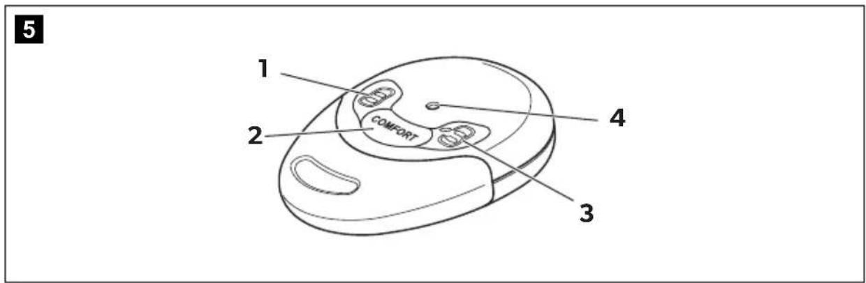
6.2 Hand-held transmitter control elements
Hand transmitters have the following control elements:
| fig. 5, page 4 Designation Function |
| 1 “Lock” button Activates the alarm system |
| 2 “COMFORT” button Activates the convenience output |
| 3 “Unlock” button Deactivates the alarm system |
| 4 LED indicator (blue) |
6.3 MagicSafe operating modes
The alarm system has the following five operating modes:
- Stand-by
The alarm system is kept in stand-by as soon as it is installed and correctly connected. However, it does not trigger the alarm when in stand-by.
- Activation time
The alarm system has an activation time of approx. 30 seconds.
The status LED on the key holder lights up as an visual indicator of the activation time.
- Armed
If the alarm system is activated, it can trigger the alarm. This happens if someone e.g. breaks the door open, opens the bonnet or enters the vehicle interior. If you wish to drive off, you must first deactivate the alarm system. The system is then in stand-by mode.
The status LED on the key holder lights up as an visual activation indicator.
- Alarm triggered
When an alarm has been triggered, this is indicated by visual and acoustic signals.
- Workshop mode
You can set the alarm to workshop mode if, for example, the vehicle is to be handed over for repairs or inspection (see chapter “Setting workshop mode” on page 51). In workshop mode, all settings for the alarm system remain stored, even if the battery is disconnected. The alarm system can be activated and deactivated without the hand-held receiver or the electronic key.
The status LED on the key holder lights up every 15 seconds as a visual indicator of the activation time.
7 Installing MagicSafe

NOTE
If you do not have sufficient technical knowledge for installing and connecting the components in vehicles, you should have a specialist install the alarm system in your vehicle.
7.1 Tools required (fig. 1, page 3)
For installation and assembly you will need the following tools:
- Measuring ruler (4)
- Centre punch (5)
- Hammer (6)
- Drill head set (7)
- Drill (8)
- Screwdriver (9)
To establish and test the electrical connection, the following tools are required:
• Diode test lamp (1) or voltmeter (2)
- Hot air blower (10)
- Crimping tool (11)
• Soldering iron (optional) (12)
- Solder (optional) (13)
• Insulating tape (14)
- Heat shrinking sleeve
- Cable bushing sleeves (optional)
To secure the cable you may require additional screws and cable binders.
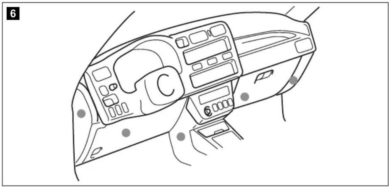
7.2 Installing the controller
▶ Select a suitable installation location (fig. 6, page 5).

NOTE
When selecting the installation location, observe the following instructions:
▶ Install the control unit
- in the vehicle interior
– with the main connection cable facing downwards - under the dashboard
- not in areas where strong electrical fields could cause interference, e.g. ignition cables or central control electronics,
- not directly next to ventilator nozzles.
▶ Where possible, use existing holes in the vehicle.
▶ Screw the control unit firmly to the vehicle with the screws supplied or use double-sided adhesive tape.
7.3 Installing the ultrasonic module
▶ Select a suitable installation location close to the control unit.
▶ Screw the ultrasonic module firmly to the vehicle with the screws supplied or use double-sided adhesive tape.
7.4 Installing the ultrasonic sensors
▶ Select a suitable installation location on the left and right A-pillars.
▶ Align the ultrasonic sensors with the middle of the rear window.
▶ Tightly fasten the ultrasonic sensors using the screws provided.
▶ Lay the cables down along the A pillar and over the dashboard to the ultrasonic module.
7.5 Installing the bonnet contact switch
This switch only needs to be installed if the vehicle does not already have one.
▶ Choose a suitable position in the engine compartment.
▶ Drill a hole with a diameter of 8 mm.
▶ During installation, make sure the distance to the closed bonnet is between 22 mm and 27 mm.
Use putty, for example, to check this distance.
You can further reduce the minimum distance by shortening the switch.
▶ Test the switch function after installation.
7.6 Installing the key holder

NOTE
When selecting the installation location, observe the cable lengths.
▶ Select a suitable installation location near the dashboard.
▶ Drill a hole with a diameter of 15 mm.
▶ Push the sensors into the holders until they lock into place.
7.7 Installing the alarm sirens (accessory)
Instead of the vehicle horn, you can connect an alarm siren (e. g. ref. no. MS-620SI or MS-670SI).

NOTICE!
When installing, ensure that the installation location is not an area where water might splash, and that it is not close to the exhaust system.
▶ Install the alarm sirens in the interior of the vehicle.
7.8 Installing additional radio sensors (accessory)
Installing the radio magnetic sensor (fig. 7, page 5)
The radio magnetic sensors allow you to lock e.g. roof boxes or caravan stowage compartments or windows.
Observe the following installation instructions:
• Install the radio magnetic sensors in the interior of the vehicle.
- The interval between the magnet (3) and sensor (1) must not exceed 15 mm.
- Align the sensor so that the LED (2) points away from the magnet (3).
▶ Tightly fasten the magnet (3) to the door or to the window.
▶ Secure the sensor (1) to a fixed component (e. g. door or window frame) using double-sided adhesive tape.
Do not cover the screws on the base with the adhesive tape.
▶ Test whether the interval is small enough:
When you open the doors, the LED (2) must light up once briefly.
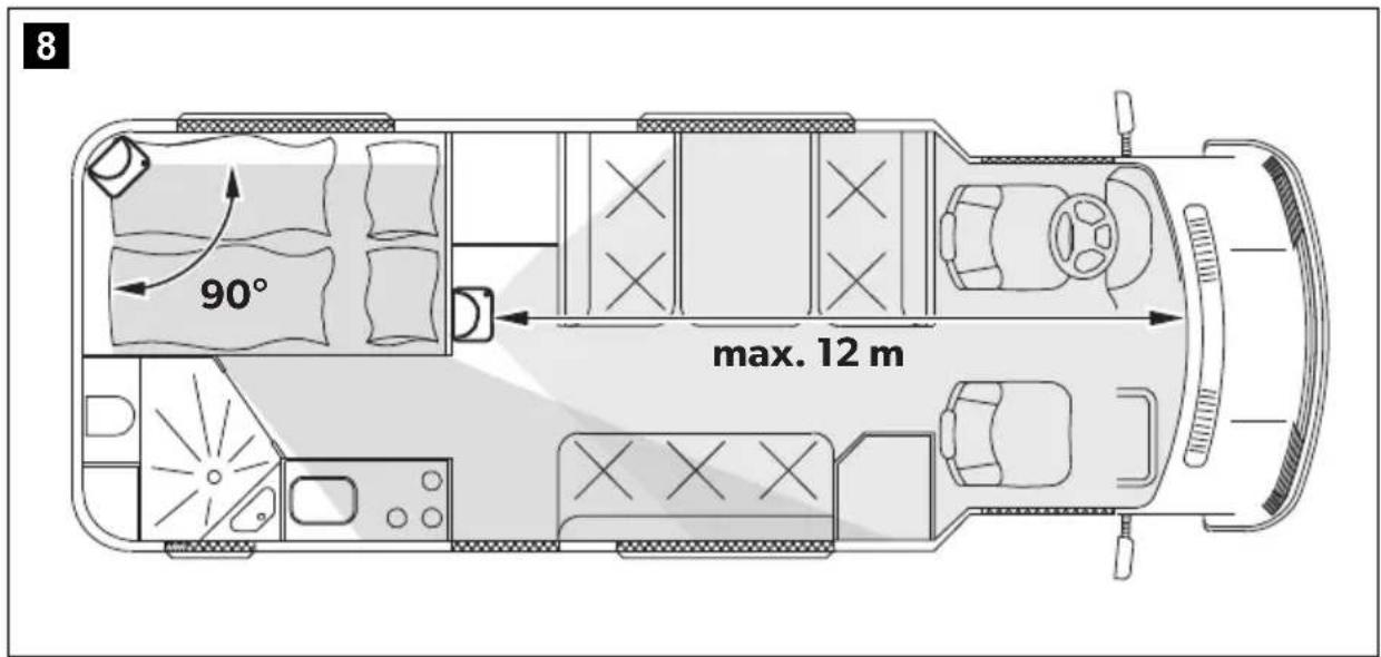
Installing the radio motion sensor
When installing the motion sensor, observe the following instructions:
- Choose an installation location that allows the entire vehicle interior to be monitored (fig. 8, page 5).
- The motion sensor can detect movements at a distance of maximum 12 m. It cannot detect movements behind stationary objects such as partitions. If appropriate, use several motion sensors.
- Try to avoid blind spots by positioning the sensors well.
- Do not install the motion sensor at a height of more than 2 m above the vehicle floor.
- Do not install the motion sensor close to sources of heat, e. g. heaters, or outlet nozzles for warm air.
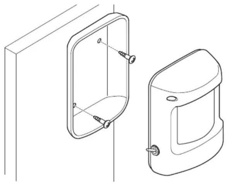
▶ Press the housing of the motion sensor in slightly on both sides and remove it from the rear wall (fig. 9, page 6)
▶ Screw the rear wall to a suitable installation location.
▶ Put the housing back onto the rear wall and click it into place.
7.9 Installing the gas detector MSG150 (accessory)
▶ Install the gas detector as described in the relevant operating manual.
8 Connecting the power to MagicSafe

NOTICE!
For vehicles with catalysers, you must shut down the fuel pump while making the electrical connections.
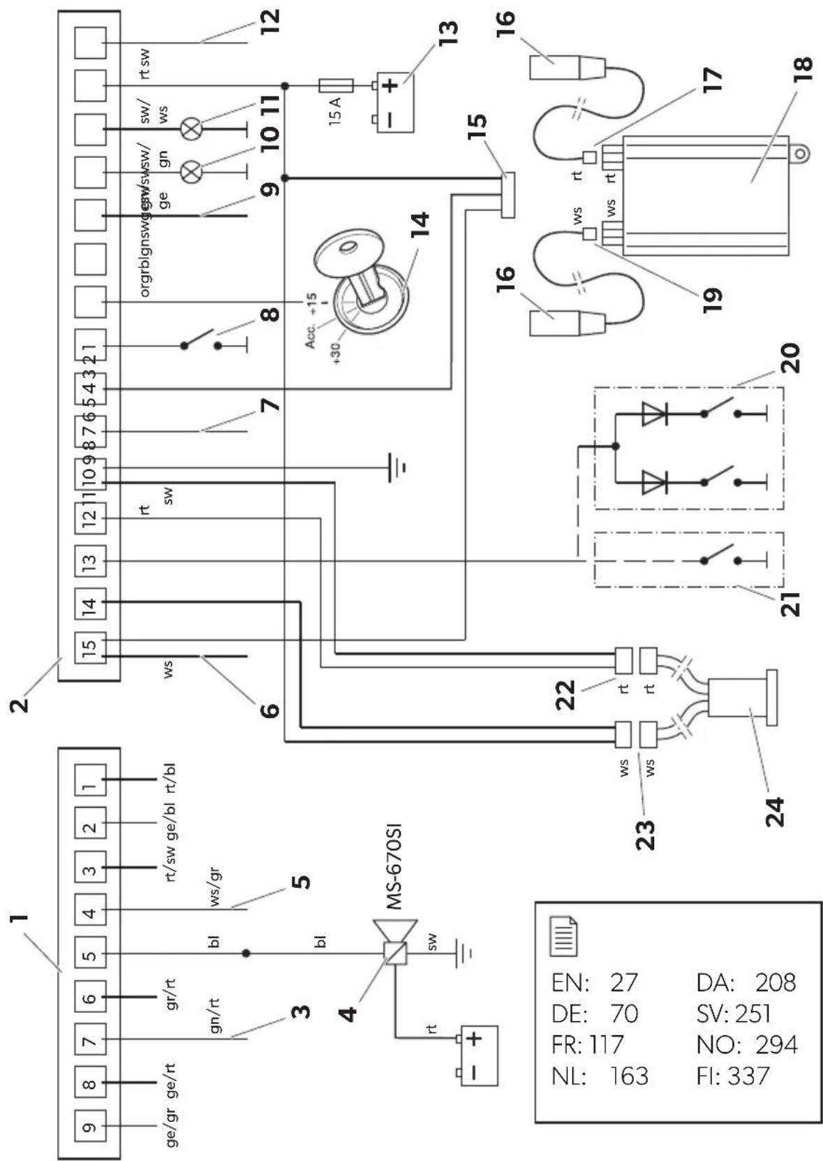
The complete circuit diagram for the alarm system can be found in fig. 11, page 7.
No. Designation
1 9-pin connection cable plug (CL)
2 15-pin connection cable plug (alarm)
3 Convenience output
4 Alarm siren with backup function (MS-670SI)
5 Earth-controlled input for optional accessory modules
6 Earth-controlled output for optional accessory modules
7 Start lock (e.g. for the fuel pump, for the starter) or horn/siren (MS-620SI)
8 Bonnet contact switch
9 Start lock (e.g. for the fuel pump, for the starter) or horn/siren (MS-620SI)
10, 11 Indicator
12 Antenna
13 Vehicle battery (starter battery)
14 Connected positive terminal (ignition, terminal 15)
No. Designation
15 3-pin plug for connection to the ultrasonic module
16 Ultrasonic sensors
17 Red plug connection ultrasonic sensor – ultrasonic module
18 Ultrasonic module
19 White plug connection ultrasonic sensor – ultrasonic module
20 Simultaneous connection to door contact switch and to the boot contact switch (with inverse diodes only!)
21 Connection to door contact switches only (without inverse diodes!)
22 Red plug connection for key holder
23 White plug connection for key holder
24 Key holder incl. status LED
All plugs are coded so that you cannot connect them incorrectly.
8.1 Laying cables
When laying the cables, make sure:
• they are not kinked or twisted
• they do not rub on edges
• they are not laid in sharp-edged ducts without protection (fig. 3, page 4).

NOTICE!
Before drilling any holes, make sure that no electrical cables or other parts of the vehicle can be damaged by drilling, sawing and filing (fig. 2, page 4).
When laying cables in the engine compartment or boot, use existing openings with rubber seals wherever possible.
Where there is no suitable opening, drill a hole with a diameter of approximately 13 mm, and insert a cable duct sleeve.

NOTE
Pull the socket connectors of the cables through the cable duct sleeve before inserting the sleeve in the bodywork.
▶ Lay the cables in the engine compartment or boot so that they cannot be damaged under any circumstances (e. g. by flying stones).
▶ Insulate all unused cable ends.
8.2 Connecting the connection cable to the control unit
▶ Insert the plug of the connection cable into the corresponding connection on the control unit
8.3 Connecting the connection cables of the 15-pole plug
Black (P1)
This cable is the antenna and does not have to be connected.
▶ Lay the antenna at an interval of at least 1 cm to metallic parts
Red (P2)
▶ Connect this cable to a cable with a permanent +12 volt charge (terminal 30).
White/black (P3)
▶ Connect this cable to the left indicator cable of the vehicle.
Black/green (P4)
▶ Connect this cable to the right indicator cable of the vehicle.
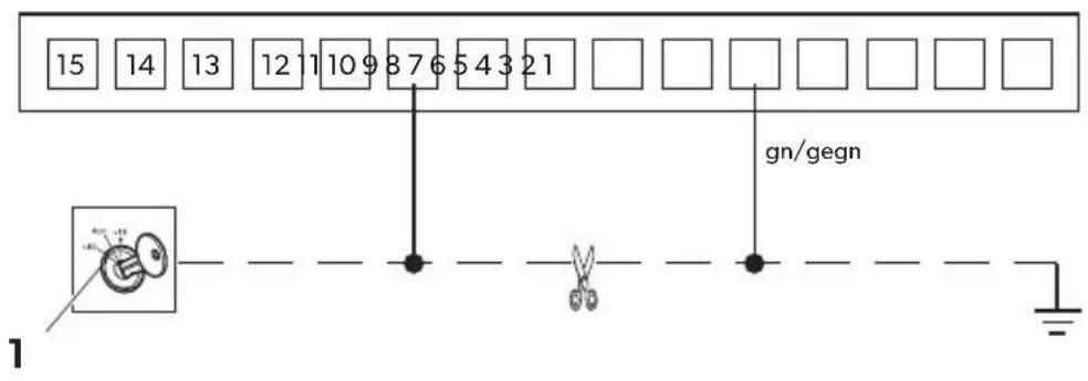
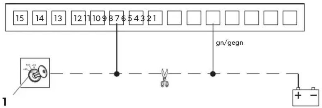
Green/yellow (P5) and green (P19), factory-set as a starter circuit breaker
These cables can break any electrical circuit (e.g. fuel pump, starter etc.). The output (green/yellow) can be charged with a maximum of 10 A.
▶ Disconnect the cable from the consumer (fig. 10 1, page 6) to earth (fig. 10 A, page 6) or to the battery (fig. 10 B, page 6).
▶ Connect the green cable and the green/yellow cable in accordance with fig. 10, page 6.
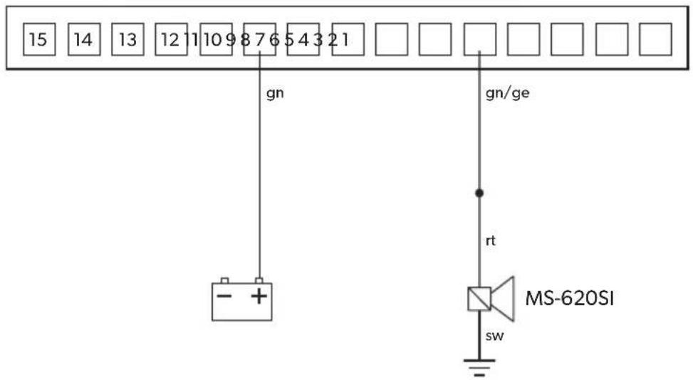
Alternatively, siren MS-620SI or the vehicle horn can be connected to the green/yellow (P5) cable (see software functions no. 13 and no. 9).
Connecting siren MS-620SI (accessory part)
▶ Connect the yellow cable and the green/yellow cable to siren MS-620SI in accordance with fig. 12, page 8.
▶ Program software function 13 to "Alarm output".
▶ Program software function 9 to "Siren".
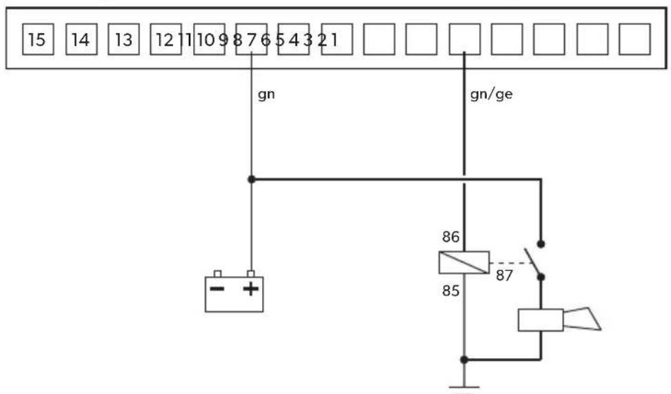
Connecting the vehicle horn
▶ Connect the yellow cable and the green/yellow cable to the vehicle horn in accordance with fig. 13, page 8.
▶ Program software function 13 to "Alarm output".
▶ Program software function 9 to "Horn".

NOTICE!
When connecting the vehicle horn, an operating current relay with a recovery diode must be used which has a rating of at least 20 A.
Free slot (P6)
Not assigned.
Orange (P7)
▶ Connect this cable to a connection which is switched by the ignition (terminal 15).
Grey (P8)
Connect this cable to the bonnet contact switch (fig. 11 8, page 7). The factory setting allows for a switch which is closed when the bonnet is open. In case an original switch is to be used which is open when the bonnet is open, this can be programmed in the control unit, see chapter "Function 15 (Bonnet contact input)" on page 40.
Blue (P9)
This is the signal cable for the ultrasonic module. It ends in the 3-pole compact plug (fig. 11 15, page 7).
Green (P10)
See P5.
Black (P11)
▶ Connect this cable to earth (terminal 31).
Red (P12)
Connects the key holder to the control unit.
Yellow (P13)

NOTE
The boot contact switch only has to be connected if the lighting for the passenger compartment (interior light) remains dark when the boot is opened. In this case, use two diodes in the yellow cable as specified in the wiring diagrams (fig. 11 20, page 7).
▶ Connect this cable to the door contact switch on the driver's door and, if required, to the boot contact switch as well.
The factory setting allows for a switch which is closed when the door is open. If the switch is open when the door is open, this can be programmed in the control unit, see chapter "Function 16 (Door contact/boot input)" on page 40.

NOTE
If it is not possible to connect the yellow cable to the door contact switch in your vehicle, you have to connect the yellow cable to earth when programming new hand-held transmitters, electronic keys or radio sensors (see chapter "Learning the hand-held transmitter, electronic key and radio sensors/reading the PIN code" on page 46).
Black (P14)
Connects the key holder to the control unit.
White + black (P15)
The white cable provides an additional earth-controlled output for optional accessory modules.
The black cable is the earth cable for the ultrasonic module.
8.4 Connecting the connection cables of the 9-pole plug (central locking)
MagicSafe features a universal connection for central locking to enable standard central locking and engine-powered retrofitted central locking to be connected to the system.
Connecting to the central locking system
▶ Determine the switching function of the original central locking system.
You will require the circuit diagram for the central locking system to do so. You can obtain this from your vehicle dealership.
If no original circuit diagrams are available, you will need to gauge the function of the control cables which run from the control unit of the central locking to the vehicle doors.

NOTICE!
Only connect MagicSafe using the control cables for the central locking and not using other cables.
Connection to other cables than the control cables or the use of an incorrect circuit plan can lead to a defect in the central locking system and the hand-held transmitter.
▶ Determine the activation time of the central locking system.
In some vehicles, for example Mercedes, an activation time of 0.7 sec. might not be sufficient to completely activate the central locking system. If so, you will need to set the control time using the software function 3 (Signal duration of the door locking contacts) to 3 sec., see chapter "Software functions" on page 36.
▶ Connect MagicSafe in accordance with the appropriate circuit diagram:
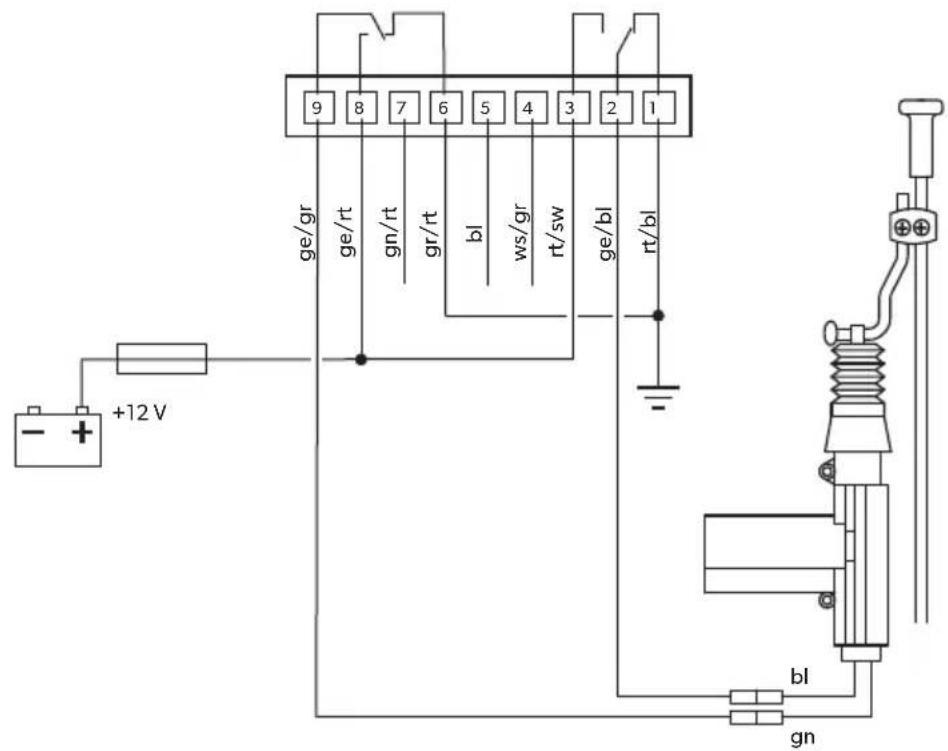
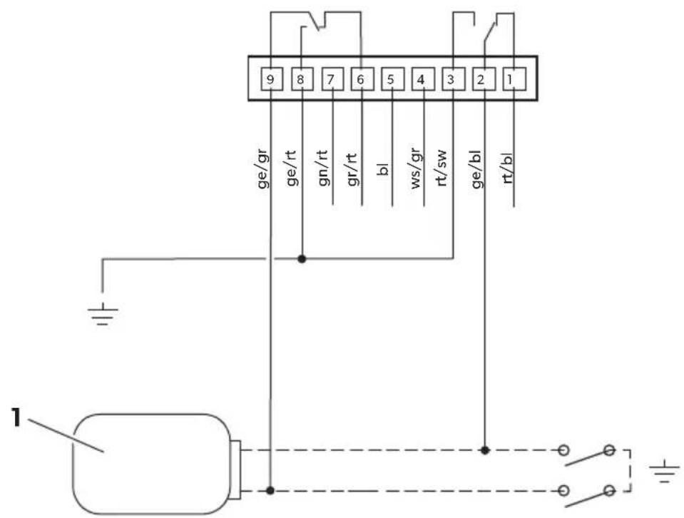
- Vehicles without a servo motor in the driver's door (driver's door cannot be locked and unlocked from the passenger's door) or with pressure vacuum central locking without electrical control cable: fig. 14, page 9
You will require an additional servo motor for this, type no. ML-11 for the driver's door.
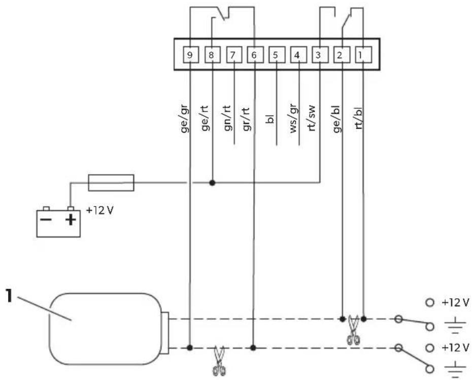
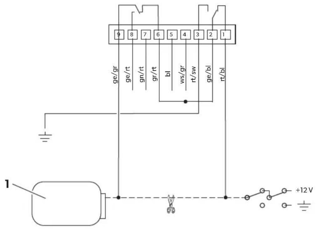
- Two cables switching from negative to +12 V: fig. 15, page 9
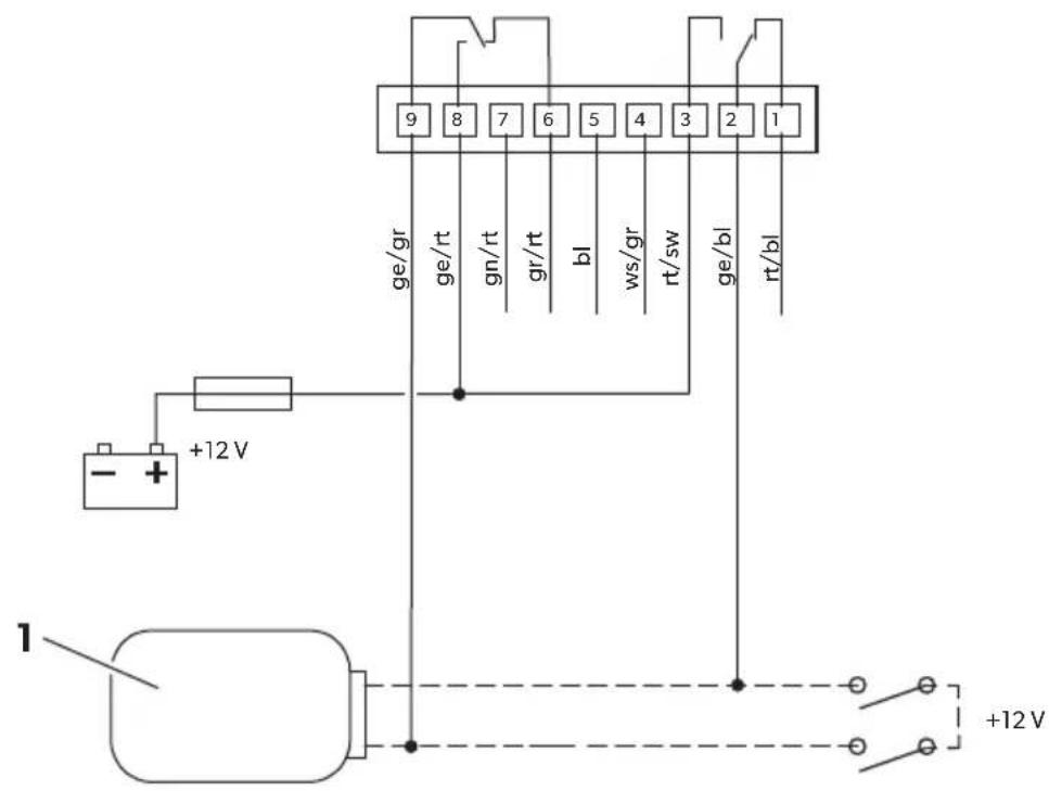
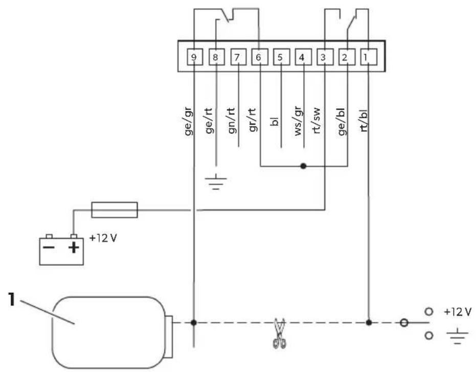
- Two +12 V pulse control cables: fig. 16, page 10
- Two negative pulse control cables: fig. 17, page 10
• One open and negative pulse control cable: fig. 18, page 11
• One +12 V and negative pulse control cable: fig. 19, page 11
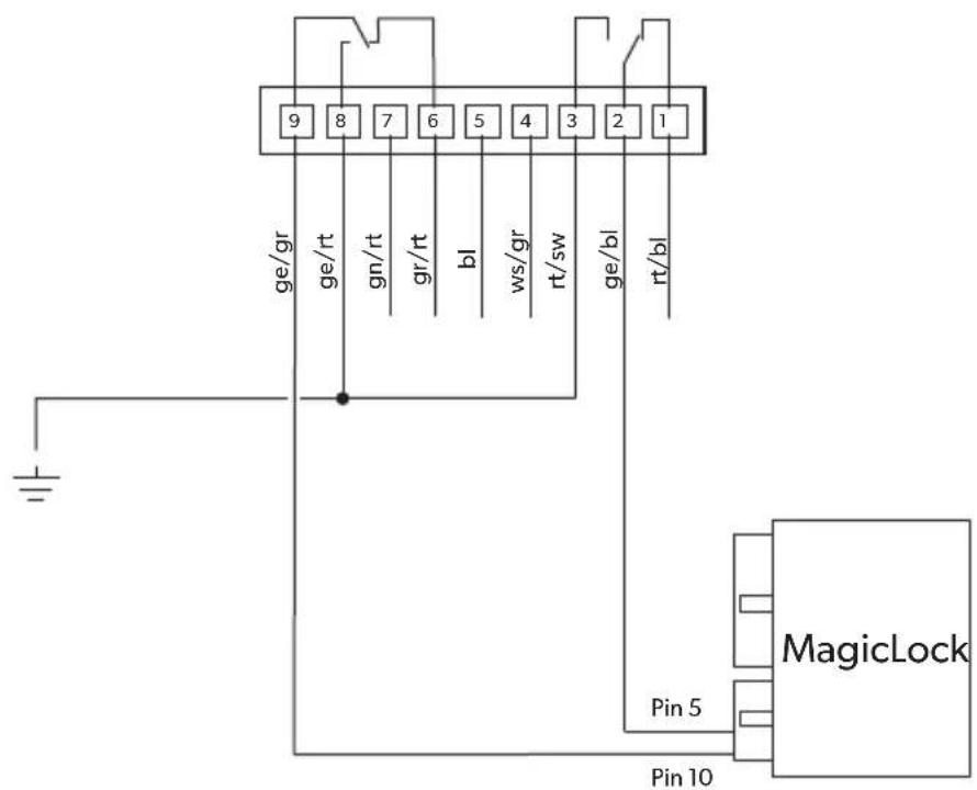
- Connection to central locking system MagicLock ML44 and ML22: fig. 20, page 12
No. in fig. 15 to fig. 19
Designation
1 Control unit for the vehicle's own central locking system
▶ Insulate any unconnected cables.
Grey/white (P4)
This cable provides an additional earth controlled input for optional accessory modules (e.g. wired magnetic contact switch).
Blue (P5)
The external backup siren MS-670SI (accessory) can be connected to this cable.
▶ Connect the blue cable to siren MS-670SI in accordance with fig. 11, page 7.
Grey cable belonging to MS-670SI
If you have installed the bonnet contact switch belonging to MS660 (see chapter "Installing the bonnet contact switch" on page 23), you have to connect it to the grey cable belonging to siren MS-670SI.
▶ Connect one end of the grey cable to the cable of the bonnet contact switch.
▶ Connect the other end of the grey cable to the grey cable (P8) belonging to MS660.
Green/red
This cable serves as a convenience output. The convenience output is earthed and can be charged with up to 1 A.

NOTICE!
When connecting consumers with a power consumption of more than 1 A (e.g. dipped headlights), an additional operating current relay must be used.
The convenience function allows you to e. g.:
- Close windows
- Close the sunroof
-
Switch on dipped headlights
-
Unlock the boot or fuel tank lid.
- Switch on the parking heating.

NOTE
You will require a convenience module or an operating current relay with recovery diode, depending on your installation, for the convenience function.
8.5 Connecting the remaining connection cables (fig. 11, page 7)
Connecting the key holder
▶ Insert the red two-pin plug (22) of the connection cable into the red socket (22) of the key holder.
▶ Insert the white two-pin plug (23) of the connection cable into the white socket (23) of the key holder.
Connecting the ultrasonic module
▶ Insert the white three-pin plug (15) into the connection of the ultrasonic module (18).
Connecting the ultrasonic senors
▶ Insert the red plug of the ultrasonic sensor cable (17) into the red connection of the ultrasonic sensor (17).
▶ Insert the white plug of the ultrasonic sensor cable (19) into the white connection of the ultrasonic sensor (19).
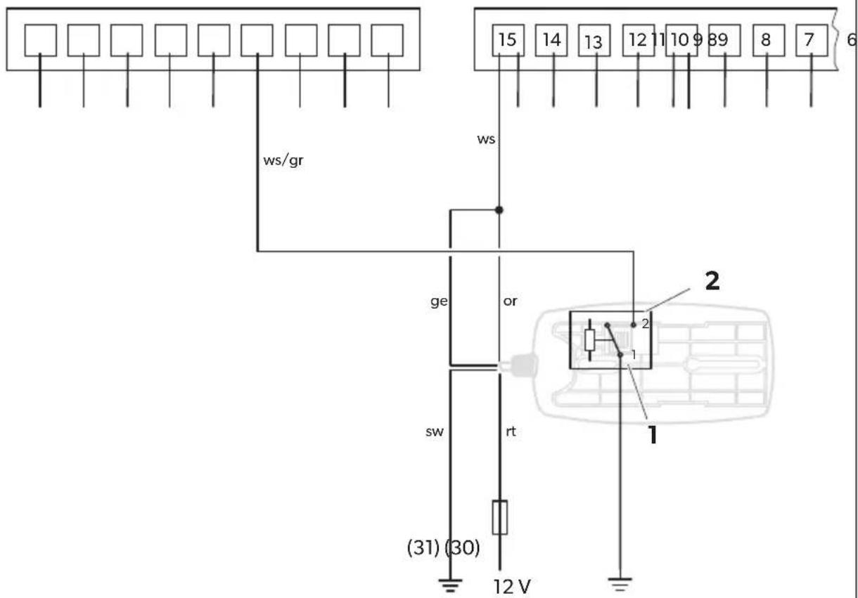
8.6 Connecting the gas detector MSG150 (accessory) (fig. 21, page 12)
▶ Disconnect the 12-volt plug from the gas detector cable.
▶ Remove around 10 cm of the outer insulation on the end of the cable.
▶ Connect the black cable to earth (terminal 31).
▶ Connect the yellow and the orange cable of the gas detector to the white cable from MS660.
▶ Connect the red cable to a cable to a permanent +12 volt charge (terminal +30). The cable must be fused with at least a 1 A fuse.
If the gas detector is also to be switched to the alarm system as the main alarm, connect both the relay contacts as follows:
▶ Connect the relay contact 1 (1) to earth (terminal 31).
▶ Connect the relay contact 2 (2) to the grey/white cable of MS660.
9 Performing a functional test
9.1 Testing the hand-held transmitter
▶ Test all of the switching functions with both hand-held transmitters.
If the system does not respond to a hand-held transmitter, program the hand-held transmitter concerned (see chapter "Learning the hand-held transmitter, electronic key and radio sensors/reading the PIN code" on page 46).

NOTE
The range of the hand-held transmitter can be restricted by solid metal parts and strong electrical fields. It is usually between 10 m and 20 m.
9.2 Checking the central locking
If you activate the alarm system (see chapter "Activating MagicSafe" on page 43), MagicSafe should lock the vehicle if central locking has been connected.
When you deactivate the alarm system (see chapter "Deactivating MagicSafe" on page 44), MagicSafe should unlock the vehicle.
If you have programmed software function 11 ("Locking/unlocking with ignition"), MagicSafe should lock the central locking approx. 5 sec. after the ignition is turned on when the doors are closed. After the ignition is turned off, MagicSafe unlocks the central locking again.
If the central locking is not working properly, proceed as follows:
▶ Check the electrical connection to the central locking.
▶ Check whether your vehicle supports software function 3 "Signal duration of the door locking contacts" (see chapter "Programming" on page 41).
▶ Check which value has been set for software function 3.
9.3 Testing the sensitivity of the ultrasonic sensors
The sensitivity of the ultrasonic sensors can be adjusted on the ultrasonic module.
▶ Turn the setting screw on the underside of the ultrasonic module in the direction of “+” to increase the sensitivity or ...
turn the setting screw of the ultrasonic module in the opposite direction to reduce the sensitivity.
To deactivate the ultrasonic module, turn the setting screw of the ultrasonic sensor as far as it will go in the opposite direction to “+”.

NOTE
If the ultrasonic sensors are set too sensitively, the alarm may be triggered by passing vehicles. For this reason set the sensitivity carefully, and not too high.
To find the right setting, proceed as follows:
▶ Deactivate the alarm system (see chapter "Deactivating MagicSafe" on page 44).
▶ Open the front side window about 20 cm.
▶ Activate the alarm system with the doors, bonnet and boot closed.
▶ Move an object into the vehicle interior from outside:
- If an alarm is triggered before you move the object into the vehicle, reduce the sensitivity.
- If no alarm is triggered, increase the sensitivity.

NOTE for convertibles and vehicles with folding tops
For vehicles with cloth or plastic roofs, the sensitivity of the ultrasonic sensors must be reduced significantly or be disabled altogether.
▶ Knock on the closed cover to check whether MagicSafe triggers the alarm when the cover moves.
9.4 Testing other alarm inputs
▶ Test the function of the other alarm inputs in order by triggering an alarm.
▶ Count the number of flashes on the status LED afterwards.
If the number of flashes does not correspond to the specified value, you need to check the connections and cables.
Number of flashes Alarm cause
| 0 (status LED off) No alarm triggered |
| 1 Voltage drop sensor |
| 2 Ultrasonic sensors (interior) |
| 3 Door/boot contact switch |
| 4 Bonnet contact switch |
| 5 Ignition |
| 7 Additional alarm input |
| 8 Radio sensor |
| 9 The battery in the hand-held transmitter is too weak |
9.5 Testing optical and acoustic signals
▶ Trigger an alarm.
During the alarm, all indicators must be switched on and the vehicle horn or alarm siren, as well as the status LED, must signal the alarm.
10 Programming MagicSafe
10.1 Software functions
MagicSafe has various software functions which you can alter in accordance with the following table. Values marked in bold indicate the factory setting.
| No. Software function “Lock” button “Unlock” button | ||
| 1 Siren sound – confirmation tone when activating and deactivating | On Off | |
| 2 Voltage drop sensor On Off | ||
| 3 Signal duration of the door locking contacts | 0.7 sec. | 3 sec. |
| 4 Convenience locking function (→ no. 19) | On Off | |
| 5 Starter circuit breaker (→ no. 13) | On Off | |
| 6 Automatic reactivation | On Off | |
| 7 Self-activation | On Off | |
| 8 Circuit time for the convenience output (→ no. 18) | 20 sec. | 1 sec. |
| 9 Siren/vehicle horn selection (→ no. 13) | Siren | Horn |
| No. | Software function | "Lock" button | "Unlock" button |
| 10 | Locking the central locking during self-activation | On Off | |
| 11 | Locking/unlocking with ignition On Off | ||
| 12 | Alarm detection for additional sensors | Additional sensor | Additional sensor and ultrasonic sensor |
| 13 | Additional relay function Starter circuit | breaker(→ no. 5) | Alarm output(→ no. 9) |
| 15 | Bonnet contact input Switch open when | the bonnet is open (12 volts) | Switch closed when the bonnet is open (0 volts) |
| 16 | Door contact/boot input Switch open when | the door is open (12 volts) | Switch closed when the door is open (0 volts) |
| 18 | Car Finder/convenience function on | Car Finder Convenienceoutput on(→ no. 8) | |
| 19 | Switch time for convenience locking function | 25 sec. (auto) Manual(→ no. 4) | |
| 20 | Deactivation of faulty door contacts | On | Off |
| 24 | Visual signals | Hazard light | Indicator |
10.2 Description of the software functions
Function 1 (Siren sound – confirmation tone when activating and deactivating)
This function enables a siren confirmation tone when the alarm system is activated and deactivated.

NOTE
By activating the acoustic confirmation tone, the alarm system no longer conforms to regulation 95/56/EC.
The operating approval for your vehicle expires within the scope of validity of this directive!
Function 2 (Voltage drop sensor)
This function allows the voltage drop sensor to be activated or deactivated.
The sensor reacts to a vehicle battery load of at least 12 watts and triggers an alarm.
Function 3 (Signal duration of the door locking contacts)
In some vehicles, (for example Mercedes-Benz), an activation time of 0.7 sec. might not be sufficient to completely activate the central locking system. In such cases, you need to set the control time to 3 sec. using this software function.
Function 4 (Convenience locking function)
This activates or deactivates the convenience locking function, see chapter "Using the convenience locking function" on page 49.
Function 5 (Starter circuit breaker)
This function allows you to activate or deactivate the starter circuit breaker.
The starter circuit breaker is activated:
- 30 sec. after the ignition was switched off ("Standby" mode, see chapter "MagicSafe operating modes" on page 20)
- 60 sec. after the ignition was switched off using the remote control ("Standby" mode, see chapter "MagicSafe operating modes" on page 20)
This function can only be used when function 13 is programmed to "Starter circuit breaker".
Function 6 (Automatic reactivation)
This function reactivates the alarm system if this was deactivated by mistake or without being noticed. This occurs when the alarm system was deactivated and no door was opened within approx. 40 sec.
Function 7 (Self-activation)
If the function is programmed to "On", the alarm system activates itself automatically when the ignition is switched off, approx. 10 sec. after the last door was closed.
Deactivation remains possible using the hand-held sensor.
Function 8 (Circuit time for the convenience output)
You can choose between 20 sec. (e.g. for shutting off the dipped headlights, Coming Home function) or 1 sec. (e.g. for opening the tailgate). This function can only be used when function 18 is programmed to “Convenience output on”.
Function 9 (Siren/vehicle horn selection)
This function determines whether the vehicle horn or an external siren (e.g.
MS-620SI) is used. When set to "Siren", the relay switches on to constant for 30 sec. When set to "Horn", the relay switches on and off every second for the duration of 30 sec. This function can only be used when function 13 is programmed to "Starter circuit breaker".
Function 10 (Locking the central locking during self-activation)
This determines whether the vehicle should be locked or not after self-activation of the alarm system. This function can only be used when function 7 is programmed to "On".
Function 11 (Locking/unlocking with ignition)
When this function is activated, you can lock the vehicle when the ignition is switched on by pressing the "Lock" button. In this case, the alarm system is not activated.
The central locking unlocks the vehicle automatically when the ignition is switched off.
Alternatively, the vehicle can be unlocked any time by pressing the "Unlock" button.
Function 12 (Alarm detection for additional sensors)
MagicSafe features an additional alarm output (grey/white cable). This function allows you to determine whether this sensor alone can trigger the alarms or whether it is only triggered in combination with the ultrasonic sensors.
Function 13 (Additional relay function)
This function is factory-set for use as a starter circuit breaker. This is already active in "Standby" mode, not just in the event of an alarm.
This function can only be used when function 5 is programmed to "On".
If function 13 is programmed to "Alarm output", then this relay can, in the event of an alarm, activate an additional warning device (e.g. a pager) or a further siren or horn. In this case, the starter circuit breaker is not activated.
The siren or horn option can be determined by function 9.
Function 15 (Bonnet contact input)
This allows you to determine how the bonnet contact switch is connected.
The system is factory-set to a closed switch when the bonnet is open (voltage 0 volts). Should the switch used be open when the bonnet is open (voltage 12 volts), function 15 must be programmed to "Switch opened when bonnet is open".
Function 16 (Door contact/boot input)
This allows you to determine how the door contact switch and the boot contact switch are connected.
The system is factory-set to a closed switch when a door is open/boot is open (voltage 0 volts). Should the switch used be open when the bonnet is open/boot is open (voltage 12 volts), function 16 must be programmed to "Switch opened when door is open".

NOTE
The boot contact switch only has to be connected if the lighting for the passenger compartment (interior light) remains dark when the boot is opened.
Function 18 (Car Finder/convenience function on)
This function allows you to determine whether the "COMFORT" button switches additional convenience functions (e.g. Coming Home function) or whether it should function as a Car Finder. In the second case, the indicators are activated for 10 min. By pressing the "COMFORT" button again, the indicator will go out, the alarm system remains activated.
If this function is programmed to "Car Finder", function 8 (Convenience function) cannot be used.
Function 19 (Switch time for convenience locking function)
In order to be able to use the convenience function, function 4 must be programmed to "On". In this case, the locking process remains activated for as long as the "Lock" button is held down. On vehicles equipped with a factory-set convenience locking module, the e.g. windows or the sliding sunroof can then be closed. Alternatively, the locking process can be programmed to a fixed duration of 25 sec.
Function 20 (Deactivation of faulty door contacts)
On vehicles without an interior light delay, this function must remain programmed to "Off" (factory setting).
On vehicles with interior light delay, this function can be programmed to "On" so that it detects doors left open by accident. As a result, the door can still be closed for the first 15 sec. after activation of the alarm system to keep it in the alarm circuit. If the door is closed after the 15 sec., it will no longer be monitored.
Function 24 (Visual signals)
A connection to the indicator cables has been provided at the factory. In the event of an alarm, both alarm system indicator outputs generate a +12 volt interval signal.
If you wish to connect the optical signals via the hazard lights switch, you must program this to "Hazard lights". In this case, a short earth signal is switched from both alarm system indicator outputs. After the alarm has finished (30 sec.), a further earth signal is switched to deactivate the hazard light system.
10.3 Programming
Starting the programming mode
▶ Deactivate the alarm system using the remote control: Press the "Unlock" button.
▶ Open the driver's door and switch on the ignition.
▶ Press and hold the "Unlock" button and switch the ignition off.
▶ Release the "Unlock" button.
√ The status LED lights up. You have now accessed the program menu.

NOTE
If 30 sec. elapse without a button being pressed, the program menu will be quit automatically.
Programming functions
The functions are programmed by pressing the button "Lock" or "Unlock" repeatedly in accordance with the number of the function, see list, page 36.
Example: You wish to activate the convenience locking function. This is function 4. Press the "Unlock" button 4 times to activate.
The status LED goes out briefly each time the button is pressed to confirm the selection. To confirm the programming step, the status LED goes out for 2 sec. The preferred value is saved.
▶ Perform all the required programming steps.
▶ To end programming, switch the ignition on.
11 Using MagicSafe
11.1 Function table
The following table lists all of the functions and how you can activate them.
| Function Condition | "Lock" button | "Unlock" button | "COM-FORT" button | |
| Activating Ignition off ● | ||||
| Deactivating Ignition off | ● | |||
| Alarm system activated | ||||
| Manual lock-ing/unlocking of the doors from the inside | Ignition on ● | |||
| Activating without interior monitoring | Ignition off ● ● (30 sec.) | |||
| Panic mode Ignition off | ● ● (1 sec.) | |||
| Alarm system activated | ||||
| Convenience output Ignition off | ● | |||
| Alarm system activated | ||||
| Convenience output Ignition off | ● | |||
| Alarm system deactivated | ||||
● Press the respective button
● ● (1 sec.) Press the button twice in a row within 1 sec.
● ● (30 sec.) Press the button twice in a row within 30 sec.
11.2 Activating MagicSafe
To activate the alarm system manually, proceed as follows:
▶ Close the doors of the vehicle.
▶ Press the "Lock" button on the hand-held transmitter for approx. 1 sec.
√ The hazard lights flash twice.
√ The alarm system is activated after approx. 30 sec. The status LED flashes in confirmation.
On vehicles with central locking, the doors and boot are locked when the alarm system is activated. If the vehicle is equipped with an original convenience function (e.g. electric windows or electric sunroof), these will also be locked. You can control the convenience function separately using the "COMFORT" button (see chapter "Using the convenience locking function" on page 49).
If the alarm system is activated when a door, the bonnet or boot is open, the status LED flashes every 3 sec. to indicate the problem.
If the door, bonnet or boot is closed within the next 15 sec., it will be reintegrated into the alarm. If the door, bonnet or boot is closed after the 15 sec. have elapsed, it will not be monitored.
Activating the alarm system so that the vehicle can remain occupied
You can set the alarm system so that the alarm system does not trigger an alarm when a movement is registered in the interior of the vehicle, e. g. to leave a pet in the vehicle.
Proceed as follows:
▶ Press the "Lock" button twice in a row within 30 sec.
√ The hazard lights flash once.
Reactivating the alarm system automatically
You can set MagicSafe so that the alarm system is reactivated automatically (software function 7 "Self-activation", factory setting: deactivated) if the vehicle is not used within 30 sec. of deactivating the alarm system (opening a door or switching on the ignition). The indicator flashes twice to indicate this.
The central locking remains unaffected. If you wish the doors to be locked by central locking self-activation, activate software function 10 "Locking the central locking during self-activation" (factory setting: deactivated).
11.3 Deactivating MagicSafe
To deactivate the alarm system manually, proceed as follows:
▶ Press the "Unlock" button on the hand-held transmitter for approx. 1 sec.
√ The hazard lights flash once.
√ If the alarm system is connected to the central locking, all doors and covers are unlocked.
Deactivating MagicSafe without the hand-held transmitter
If you have misplaced the hand-held transmitter, the batteries are empty, or the hand-held transmitter is damaged, you can deactivate the alarm system with the electronic key.
▶ Open the door using the vehicle key.
√ The alarm system triggers an alarm.
▶ Insert the electronic key in the socket.
√ The alarm system is deactivated.
If the electronic key has also been lost, the alarm system can be deactivated using the PIN code. To enter the 5-digit PIN code, proceed as follows:
▶ Open the driver's door using the ignition key, triggering an alarm by doing so.
▶ Wait 30 sec. until the alarm stops.
√ The status LED lights up continuously.
▶ Switch the ignition on for 1 sec. and off again within 5 sec.
√ The status LED starts flashing.
▶ Count the number of flashes until the number agrees with the first number of your PIN code.
1 flash = number 1, 2 flashes = number 2, ..., 9 flashes = number 9, 10 flashes = number 0.
▶ After the corresponding flashing signal, switch the ignition on for 1 sec. and off again when the LED has gone out. This confirms the number.
√ The status LED starts flashing again.
▶ Confirm all numbers in the PIN code in the same way.
Example: The system PIN code is "01234".
- Status LED flashes 10 x (= number 0), then switch the ignition on and off.
- Status LED flashes 1 x (= number 1), then switch the ignition on and off.
- Status LED flashes 2 x (= number 2), then switch the ignition on and off.
- Status LED flashes 3 x (= number 3), then switch the ignition on and off.
- Status LED flashes 4 x (= number 4), then switch the ignition on and off.
The PIN code has been entered.
√ If you have entered the PIN code correctly, the alarm system will be in workshop mode, see chapter "Setting workshop mode" on page 51.
If you have entered the PIN code incorrectly, the alarm will start again. In this case, repeat the procedure from the start.

NOTE
Please note that every time a new hand-held transmitter or wireless radio sensors (magnetic contact switch or motion detector) are programmed, the PIN code is changed! It is therefore vital that the new PIN code is noted in the manual for every learning process.
11.4 Controlling the central locking with MagicSafe

NOTE
When locking using the hand-held transmitter, the ignition must be switched on. Otherwise the alarm system will be activated as well.
If your vehicle features central locking, you can lock or unlock doors automatically from the inside. This function has been factory-set to deactivated. To activate it, process as follows:
▶ Program software function 11 "Locking/unlocking with ignition" to "On", see chapter "Software functions" on page 36.
When the ignition is switched on, the central locking will now lock the vehicle when the "Lock" button is pressed for 3 sec. The alarm system remains deactivated.
If you switch the ignition off, all doors will be unlocked without delay.
11.5 Learning the hand-held transmitter, electronic key and radio sensors/reading the PIN code

NOTE
- Learn all hand-held transmitters, electronic keys and radio sensors (accessory) which you wish to use during the same programming phase. This also applies for hand-held receivers which you have used previously, or radio sensors which have already been paired!
- Learn the hand-held transmitter and the electronic key first, then – if applicable – the radio motion detector (accessory) and then the radio magnetic sensors (accessory).
Proceed as follows to learn hand-held transmitters, electronic keys as well as radio sensors (e.g. radio motion detector, radio magnetic sensors – accessory):
Switching to learning mode
▶ Deactivate the alarm system by pressing the "Unlock" button.
▶ Open the driver's door.
▶ If you have not connected a door contact switch, you need to connect the yellow cable belonging to MS660 to an earth point.
Maintain this connection throughout the entire programming process.
▶ Switch on the ignition.
▶ Press and hold down the "COMFORT" button.
▶ Switch the ignition off.
▶ Release the button.
√ You are now in learning mode.
√ The status LED flashes 10 times and then lights up continuously to confirm.

NOTE
If you do not press a button within 10 seconds, you will exit the learning mode.
Learning the hand-held transmitter
▶ Press the "COMFORT" button on the hand-held transmitter.
√ The status LED goes out while the value is saved.
√ If the status LED lights up continually again, then the hand-held receiver has been learned and you can now proceed with the next one.

NOTE
Only exit learning mode when you have learned all the hand-held receivers, electronic keys and radio sensors you wish to use. Hand-held receivers and radio sensors which you do not learn during this phase will be automatically unpaired from the system. They can only be used once they have been learned again.
Learning the electronic key
▶ Insert the electronic key into the key holder on the dashboard.
√ The status LED goes out while the value is saved.
√ If the status LED lights up continually again, then the hand-held receiver has been learned and you can now proceed with the next one.
Learning the radio motion detector (accessory)
▶ Switch the motion detector on using the switch.
√ The read status LED on the motion detector flashes.
√ The motion detector has been learned.
Learning the radio magnetic sensor (accessory)
▶ Disconnect the magnetic sensor contact (e. g. by opening a door secured by the radio magnetic sensor).
√ The read status LED on the magnetic sensor flashes once.
√ The magnetic sensor has been learned.
Reading the PIN code
Once all hand-held transmitters and radio sensors (accessory) have been learned, the status LED starts to flash after 10 sec. This sequence shows the new, updated PIN code.
▶ Take a reading of the current PIN code.
Example:
Status LED flashes 10 x, then 2 sec. pause = number 0
Status LED flashes 1 x, then 2 sec. pause = number 1
Status LED flashes 2 x, then 2 sec. pause = number 2
Status LED flashes 3 x, then 2 sec. pause = number 3
Status LED flashes 4 x = number 4
The system PIN code is 0 1 2 3 4.
I
NOTE
- Make a note of the PIN code and keep it in a safe place (e.g. at the end of this manual, see page 56)!
- The PIN code is changed every time the hand-held transmitters are learned.
Exiting learning mode
▶ Switch on the ignition.
▶ Switch the ignition off.
▶ If you connected the yellow cable belonging to MS660 to an earth point for the programming process, you now need to remove this connection.
▶ Insulate and store the yellow cable.
Testing the hand-held transmitter
▶ Test the new hand-held transmitter. If a hand-held receiver does not function, then they must all be learned again.
11.6 Using the convenience locking function
If the vehicle has been equipped with a convenience module and software function 4 "Convenience locking function" is activated, you can use the hand-held transmitter to, e. g.:
- Close windows
- Close the sunroof
- Lock the boot or fuel tank lid
- Switch on dipped headlights
- Switch on the parking heating
To do this, proceed as follows:
▶ Press and hold the "Lock" button until e. g. the vehicle windows have closed completely.

NOTE
Alternatively, you can program the control to a fixed duration of 25 sec. (software function 19, see chapter "Programming MagicSafe" on page 36).
11.7 Displaying the cause of the alarm
MagicSafe stores triggered alarms. The memory can display the last five alarm situations.
If an alarm was triggered, this is indicated by a short flashing of the indicator (0.5 sec.) when the vehicle is unlocked.
This is how to display the cause of the alarm:
▶ Deactivate the alarm system by pressing the "Unlock" button.
▶ Press the "Lock" and "Unlock" buttons simultaneously.
√ The status LED shows the last five saved alarm causes in the form of flashing signals, in accordance with the following list:
| Number of flashes | Cause of the alarm |
| 1 Voltage drop sensor | |
| 2 Ultrasonic sensors (interior) | |
| 3 Door/boot contact switch | |
| 4 Bonnet contact switch | |
| 5 Ignition | |
| 7 Additional alarm input | |
| 8 Radio sensor | |
| 9 The battery in the hand-held transmitter is too weak | |
11.8 Using the self-activation function
Self-activation (factory setting: deactivated) refers to the automatic arming of the alarm system after leaving the vehicle. The ignition must be switched off for this and the doors must be closed.
To set up self-activation, proceed as follows:
▶ Program software function 7 "Self-activation" to "On".
√ The alarm system activates itself 10 sec. after the ignition was switched off and a door was opened and closed again.

NOTE
If you have set the system to self-activate, the central locking does not lock the doors, to prevent you locking yourself out of the car by accident.
11.9 Setting workshop mode
You can set the alarm to the so-called workshop mode if, for example, the vehicle is to be handed over for inspection or repairs. In workshop mode, all settings for the alarm system remain stored, even if the battery is disconnected.
To do this, proceed as follows:
▶ Deactivate the alarm system.
▶ Close all the doors.
▶ Switch on the ignition.
▶ Press the "Lock" button three times within 5 sec.
√ Workshop mode is switched on.
√ The indicators light up once to confirm.
Switching off workshop mode
▶ Press the "Lock" button.
√ Workshop mode is switched off.
√ The indicators light up once to confirm and the central locking opens.
11.10 Using the panic mode
The alarm system has a panic mode. You can trigger the alarm by hand-held transmitter, for example, to scare off an assailant if you are attacked. For this function, the ignition must be switched off and the alarm system in activated mode.
To activate the panic mode, proceed as follows:
▶ Press the "Lock" button briefly twice in a row.
√ The vehicle horn or alarm siren is switched on.
√ The hazard lights flash.
Switching off the panic mode
▶ Press the "Unlock" button on the hand-held transmitter.
√ The panic mode is switched off.
11.11 Replacing the batteries
Please observe the following instructions for batteries:

WARNING!
Keep the batteries out of reach of children.
- Only use leak-proof batteries that are suitable for electronic devices.
-
Never attempt to do the following with batteries:
-
recharge them,
- open them or
- throw them in fires.
- Dispose of old batteries appropriately.
Changing the battery in the hand-held transmitter
If the hand-held transmitter's range is reduced noticeably or if the control LED flickers during transmission, the battery needs to be replaced.
▶ Undo the screw on the bottom of the hand-held transmitter.
▶ Open the hand-held transmitter.

NOTICE!
Ensure the polarity of the batteries is correct when inserting. The positive pole is at the top.
▶ Change the battery (battery type CR 2032, 3 volts).
▶ Refit the lid on the hand-held transmitter and re-insert the screw.
Changing the battery in the radio motion detector (accessory)
▶ Press the housing of the motion detector in slightly on both sides and remove it.
▶ Change the battery (9 volt battery).
▶ Put the housing back onto the rear wall and click it into place.
Changing the battery in the radio magnetic sensor (accessory)
▶ Take off the sensor.
▶ Undo both screws on the back of the sensor.
▶ Open the sensor.

NOTICE!
Ensure the polarity of the batteries is correct when inserting. The positive pole is at the top.
▶ Change the battery (battery type CR 2032, 3 volts).
▶ Refit the lid on the sensor and re-insert the screw.
▶ Reattach the sensor.
12 Troubleshooting
The range of the hand-held transmitter is decreasing.
The batteries are flat.
You have lost the hand-held transmitter or it has been damaged.
▶ Deactivate the alarm system using the electronic key or the PIN code (see chapter "Deactivating MagicSafe without the hand-held transmitter" on page 44).
The indicators flash only once within 2 sec. instead of twice when you switch the alarm system on.
The alarm system is warning you that a door or the bonnet or boot is open.
▶ Deactivate the alarm system.
▶ Rectify the fault.
▶ Reactivate the alarm system.
The indicators flash only once briefly (0.5 sec.) instead of once for longer when you switch the alarm system off.
The alarm system has triggered an alarm.
▶ Sort the alarm memory.
This indicates the sensor which has triggered the alarm (see corresponding table in chapter “Displaying the cause of the alarm” on page 49).
You deactivated the alarm system a few minutes ago, but the alarm system has switched itself back on again.
The alarm system has possibly detected that you have not entered the vehicle and has therefore automatically switched itself on and locked all the doors if this function has been programmed (software function 7 "Self-activation").
▶ Open a door or the bonnet/boot open to avoid this.
13 Care and cleaning

NOTICE!
Do not use sharp or hard objects or cleaning agents for cleaning as these may damage the product.
▶ Occasionally clean the product with a damp cloth.
14 Guarantee
The statutory warranty period applies. If the product is defective, please contact the manufacturer's branch in your country (see the back of the instruction manual for the addresses) or your retailer.
For repair and guarantee processing, please send the following items:
- Defect components
• A copy of the receipt with purchasing date - A reason for the claim or description of the fault
15 Disposal
▶ Place the packaging material in the appropriate recycling waste bins wherever possible.
If you wish to finally dispose of the product, ask your local recycling centre or specialist dealer for details about how to do this in accordance with the applicable disposal regulations.

Protect the environment!
Do not dispose of any batteries with general household waste.
Return defective or used batteries to your retailer or dispose of them at collection points.
16 Technical data

NOTE
The alarm system has a low power consumption (< 20 mA). You can leave your vehicle with the alarm system activated for several weeks without discharging the vehicle battery.
Controller
| Operating voltage: | 12 V--- (9 - 15 V---) |
| Current consumption: < 20 mA (activated) | < 7 mA (deactivated) |
| Operating temperature: -40 °C to +85 °C | |
| Dimensions (W x D x H): 105 x 100 x | 25 mm |
Hand-held transmitter
| Frequency: 433.992 MHz | |
| Coding: Changing code system | |
| Operating voltage: 3 V | |
| Range: Up to 20 m | |
| Battery type: CR2032, 3 volts | |
| Operating temperature: -40 °C to +85 °C | |
| Dimensions (W x D x H): 54 x 39 x 12 mm |
Certifications
The device has e1 certification and R&TTE certification.

A-00 0267
PIN code
Always make a note of the current PIN code!
PIN code PIN code
6 Description technique
▶ Raccordez ce câble à la masse (borne 31).
Rouge (P12)
11.3 MagicSafe deactiveren
Blinker 1x = ciffer 1, blinker 2x = ciffer 2, ..., blinker 9x = ciffer 9, blinker 10x = ciffer 0.
11.3 Avaktivera MagicSafe
11.3 Deaktivere MagicSafe
Dometic Australia Pty. Ltd.
1 John Duncan Court
Varsity Lakes QLD 4227
1800212121
+61 7 55076001
Mail: sales@dometic.com.au
AUSTRIA
Dometic Austria GmbH
Neudorferstraße 108
A-2353 Guntramsdorf
+43 2236 908070
+43 2236 90807060
Mail: info@dometic.at
BENELUX
Dometic Branch Office Belgium
Zincstraal 3
B-1500 Halle
+32 2 3598040
+32 2 3598050
Mail: info@dometic.be
BRAZIL
Dometic DO Brasil LTDA
Avenida Paulista 1754, conj. 111
SP 01310-920 Sao Paulo
+551132513352
+551132513362
Dometic Group Asia Pacific
Suites 2207-11 · 22/F · Tower 1
The Gateway · 25 Canton Road,
Tsim Sha Tsui · Kowloon
+852 2 4611386
+852 2 4665553
Mail: info@waeco.com.hk
HUNGARY
Dometic Zrt. Sales Office
Kerékgyártó u. 5.
H-1147 Budapest
+3614684400
+3614684401
Dometic Italy S.r.l.
Via Virgilio, 3
I-47122 Forlì (FC)
+39 0543 754901
+390543754983
Mail: vendite@dometic.it
JAPAN
Dometic KK
Maekawa-Shibaura, Bldg. 2
2-13-9 Shibaura Minato-ku
Tokyo 108-0023
+81 3 5445 3333
+81 3 5445 3339
Mail: info@dometic.jp
MEXICO
Circuito Médicos No. 6 Local 1
Colonia Ciudad Satélite
CP 53100 Naucalpan de Juárez
Estado de México
+52 55 5374 4108
+52 55 5393 4683
Mail: info@dometic.com.mx
NETHERLANDS
Dometic Benelux B.V.
Ecustraat 3
NL-4879 NP Etten-Leur
+31 76 5029000
+31 76 5029019
Mail: info@dometic.nl
NEW ZEALAND
Dometic New Zealand Ltd.
Unite E, The Gate
373 Neilson Street
Penrose 1, Auckland
+6496221490
+6496221573
Mail: customerservices@dometic.co.nz
NORWAY
Dometic Norway AS
∅sterøyveien 46
N-3232 Sandefjord
+47 33428450
+47 33428459
Mail: firmapost@dometic.no
POLAND
Dometic Poland Sp. z o.o.
Ul. Puławska 435A
PL-02-801 Warszawa
+48 22 414 3200
+48 22 414 3201
Mail: info@dometic.pl
PORTUGAL
Dometic Spain, S.L.
Komsomolskaya square 6-1
RU-107140 Moscow
+7 495 780 79 39
+7 495 916 56 53
Mail: info@dometic.ru
SINGAPORE
Dometic Pte Ltd
18 Boon Lay Way 06-140 Trade Hub 21
Singapore 609966
+65 6795 3177
+65 6862 6620
Mail: dometic@dometic.com.sg
SLOVAKIA
Dometic Slovakia s.r.o. Sales Office Bratislava
Nádražná 34/A
900 28 Ivánka pri Dunaji
/ +421 2 45 529 680
Mail: bratislava@dometic.com
SOUTH AFRICA
Dometic (Pty) Ltd.
Regional Office
South Africa & Sub-Saharan Africa
2 Avalon Road
West Lake View Ext 11
Modderfontein 1645
Johannesburg
+27114504978
+27114504976
Mail: info@dometic.co.za
SPAIN
Dometic Spain S.L.
Avda. Sierra del Guadarrama, 16
E-28691 Villanueva de la Cañada
Madrid
+34902111042
+34 900 100 245
Mail: info@dometic.es
SWEDEN
Dometic Scandinavia AB
Gustaf Melins gata 7
Dometic Switzerland AG
Riedackerstrasse 7a
CH-8153 Rümlang
+41 44 8187171
+41 44 8187191
Mail: info@dometic.ch
UNITED ARAB EMIRATES
Dometic Middle East FZCO
P.O.Box17860
S-D 6, Jebel Ali Freezone
Dubai
+97148833858
+97148833868
Mail: info@dometic.ae
UNITED KINGDOM
Dometic UK Ltd.
Dometic House, The Brewery
Blandford St. Mary
Dorset DT119LS
+44 344 626 0133
+44 344 626 0143
Mail: customerservices@dometic.co.uk
USA
Dometic RV Division
1120 North Main Street
Elkhart, IN 46515
+1574-264-2131