
PWS-100TD1 - Audio/video converter SONY - Free user manual and instructions
Find the device manual for free PWS-100TD1 SONY in PDF.

| Product Type | Audio/Video Converter |
| Brand | Sony |
| Model | PWS-100TD1 |
| Dimensions (W × H × D) | 440 × 43.6 × 640 mm |
| Weight | 14 kg |
| Power Supply | 100 V – 240 V AC, 50/60 Hz, 235 W |
| Standby Power Consumption | ≤ 3 W |
| Operating Temperature | 5 °C to 35 °C |
| Operating Humidity | 20 % to 90 % RH |
| Processor | Intel Core i7-6700TE (2.4 GHz) |
| RAM | 8 GB SO-DIMM DDR4 |
| Internal Storage | 12 hard drives of 500 GB (2.5-inch) |
| Supported RAID | 2D+1P, 3D+1P, 5D+1P |
| SDI Interfaces | 4 BNC inputs/outputs (HD/SD) |
| USB Interfaces | 6 USB 3.0 Type A ports (2 front, 4 rear) |
| Network Interfaces | 2 Gigabit Ethernet ports (RJ-45) |
| Video Output | 1 HDMI, 1 DisplayPort |
| Main Functions | SDI acquisition, quality control, HDD and ODA storage, workflow, web application, software integration |
| Operating System | Windows 8 |
| Included Accessories | 2 RJ-45/D-sub conversion cables |
| Option | Redundant Power Supply PWSK-101 |
| Maintenance | Avoid shocks, vibrations, extreme temperatures; replace hard drive every 2 to 5 years |
| Security | Configure passwords, SSL certificates, use an UPS |
Frequently Asked Questions - PWS-100TD1 SONY
User questions about PWS-100TD1 SONY
0 question about this device. Answer the ones you know or ask your own.
Ask a new question about this device
Download the instructions for your Audio/video converter in PDF format for free! Find your manual PWS-100TD1 - SONY and take your electronic device back in hand. On this page are published all the documents necessary for the use of your device. PWS-100TD1 by SONY.
USER MANUAL PWS-100TD1 SONY
Japanese/English/French/German/Italian/Spanish/Chinese/Korean
1st Edition (Revised 5)
目次
概要 3
システム構成例 4
対応機器....9
対応 VTR 9
対応 ODS ドライブ....9
各部の名称と働き....10
前面 10
①FAN インジケーター
① SYSTEM TC 端子
本システムでは使用しません。
Supported Devices.... 26
Supported VTRs 26
Supported ODS Drives.... 26
Name and Function of Parts.... 27
Front View.... 27
Front View (Panel Removed).... 27
Rear View.... 28
Setting Up 29
Initial Settings.... 29
Displaying the Web Application 30
System Settings 31
Installing Certificates 31
Library Licenses 32
Maintenance Web Application Operation.... 32
Usage Precautions.... 32
Specifications.... 33
For safety, please read the precautions described in the PWS-100 Operation Guide (supplied).
Overview
The PWS-100TD1 is a system for digitizing VTR material to create clips and for storing clips on cartridges in an Optical Disc Archive System. It features the following functions.
Ingest
The unit creates high-resolution video and proxy video files from input SDI signals from one or more VTRs and stores the ingested clips on internal HDDs. It can also control VTR devices remotely using an RS-422 interface.
Video quality checking
The video quality of ingested clips can be checked automatically. The video can also be checked visually by an operator in the web application screen or on an external monitor.
Clip storage
High-resolution clips can be transferred and stored on cartridges or on a network server.
Workflows
A series of tasks, from ingesting through to transfer of clips, can be executed in a single operation using workflows. A manager can defines the workflow tasks to execute and assign an operator to execute the tasks in a work order, and the operator then executes the tasks according to the work order.
Web application
Control and configuration of the unit is performed using a graphical interface displayed in a web browser on a client PC.
Integration with management software
The properties of clips stored on cartridges and proxy video files can be exported and managed using other software.
System Configuration Examples
Connect VTRs and external monitors to the SDI connectors of the unit, and drive units to the USB connectors on the rear panel. You can select a 2-input/2-output, 3-input/1-output, or 4-input system configuration by configuring SDI settings in the web application.
2 inputs/2 outputs
Connect VTRs to the SDI 1 and SDI 2 connectors, and external monitors to the SDI 3 and SDI 4 connectors. You can use this configuration to digitize video from two VTRs in parallel.
Notes
- If multiple VTRs are connected, make sure that all VTRs are synchronized (± 1H) .
- Set the EE/PB setting of the VTR to PB.
flowchart
graph TD
    A["Operator Operator Manager"] --> B["Gigabit Ethernet"]
    B --> C["External monitor"]
    C --> D["HD SDI"]
    C --> E["HD SDI"]
    C --> F["HD SDI"]
    C --> G["HD SDI"]
    C --> H["HD SDI"]
    C --> I["HD SDI"]
    C --> J["HD SDI"]
    C --> K["HD SDI"]
    C --> L["HD SDI"]
    C --> M["HD SDI"]
    C --> N["HD SDI"]
    C --> O["HD SDI"]
    C --> P["HD SDI"]
    C --> Q["HD SDI"]
    C --> R["HD SDI"]
    C --> S["HD SDI"]
    C --> T["HD SDI"]
    C --> U["HD SDI"]
    C --> V["HD SDI"]
    C --> W["HD SDI"]
    C --> X["HD SDI"]
    C --> Y["HD SDI"]
    C --> Z["HD SDI"]
    C --> AA["HD SDI"]
    C --> AB["HD SDI"]
    C --> AC["HD SDI"]
    C --> AD["HD SDI"]
    C --> AE["HD SDI"]
    C --> AF["HD SDI"]
    C --> AG["HD SDI"]
    C --> AH["HD SDI"]
    C --> AI["HD SDI"]
    C --> AJ["HD SDI"]
    C --> AK["HD SDI"]
    C --> AL["HD SDI"]
    C --> AM["HD SDI"]
    C --> AN["HD SDI"]
    C --> AO["HD SDI"]
    C --> AP["HD SDI"]
    C --> AQ["HD SDI"]
    C --> AR["HD SDI"]
    C --> AS["HD SDI"]
    C --> AT["HD SDI"]
    C --> AU["HD SDI"]
    C --> AV["HD SDI"]
    C --> AW["HD SDI"]
    C --> AX["HD SDI"]
    C --> AY["HD SDI"]
    C --> AZ["HD SDI"]
    C --> BA["HD SDI"]
    C --> BB["HD SDI"]
    C --> BC["HD SDI"]
    C --> BD["HD SDI"]
    C --> BE["HD SDI"]
    C --> BF["HD SDI"]
    C --> BG["HD SDI"]
    C --> BH["HD SDI"]
    C --> BI["HD SDI"]
    C --> BJ["HD SDI"]
    C --> BK["HD SDI"]
    C --> BL["HD SDI"]
    C --> BM["HD SDI"]
    C --> BN["HD SDI"]
    C --> BO["HD SDI"]
    C --> BP["HD SDI"]
    C --> BQ["HD SDI"]
    C --> BR["HD SDI"]
    C --> BS["HD SDI"]
    C --> BT["HD SDI"]
    C --> BU["HD SDI"]
    C --> BV["HD SDI"]
    C --> BW["HD SDI"]
    C --> BX["HD SDI"]
    C --> BY["HD SDI"]
    C --> BZ["HD SDI"]
    C --> CA["HD SDI"]
    C --> CB["HD SDI"]
    C --> CC["HD SDI"]
    C --> CD["HD SDI"]
    C --> CE["HD SDI"]
    C --> CF["HD SDI"]
    C --> CG["HD SDI"]
    C --> CH["HD SDI"]
    C --> CI["HD SDI"]
    C --> CJ["HD SDI"]
    C --> CK["HD SDI"]
    C --> CR["HD SDI"]
    C --> CS["HD SDI"]
    C --> CT["HD SDI"]
    C --> CU["HD SDI"]
    C --> CV["HD SDI"]
    C --> CW["HD SDI"]
    C --> CX["HD SDI"]
    C --> CY["HD SDI"]
    C --> CZ["HD SDI"]
    C --> DA["HD SDI"]
    C --> DB["HD SDI"]
    C --> DC["HD SDI"]
    C --> DD["HD SDI"]
    C --> DE["HD SDI"]
    C --> DF["HD SDI"]
    C --> DG["HD SDI"]
    C --> DH["HD SDI"]
    C --> DI["HD SDI"]
    C --> DJ["HD SDI"]
    C --> DK["HD SDI"]
    C --> DL["HD SDI"]
    C --> DV["HD SDI"]
    C --> DW["HD SDI"]
    C --> DX["HD SDI"]
    C --> DY["HD SDI"]
    C --> DYD["HD SDI"]
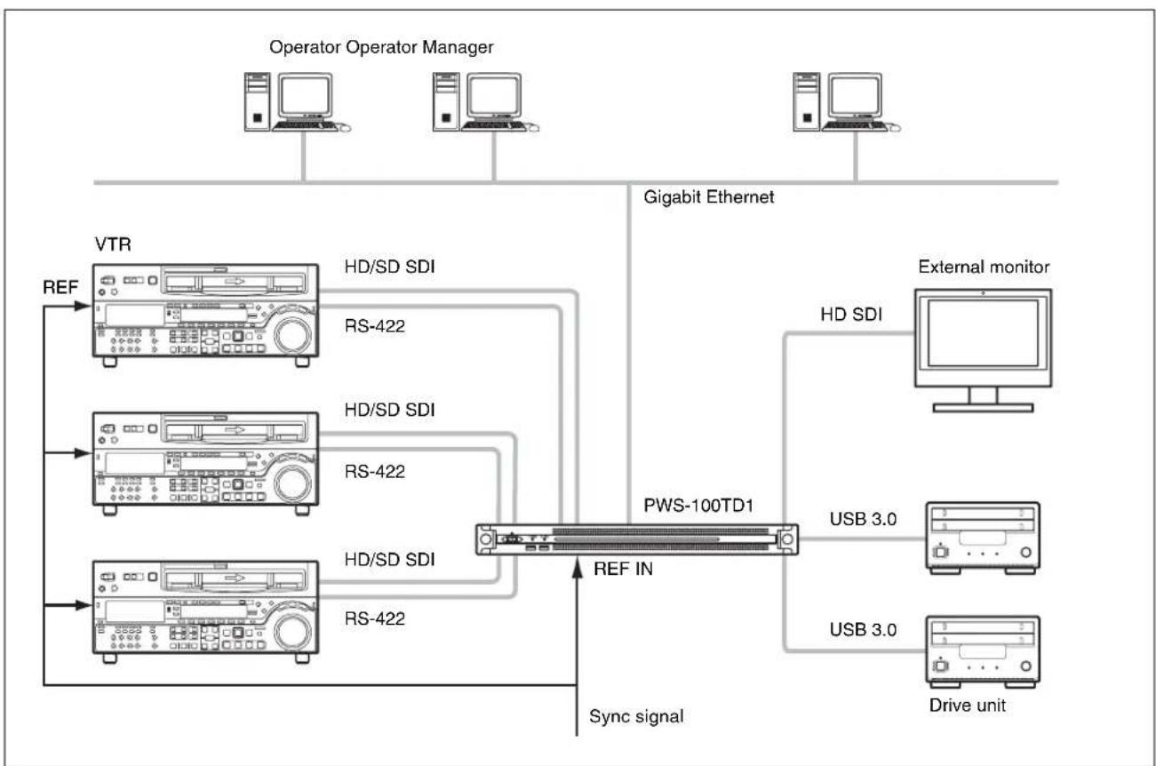
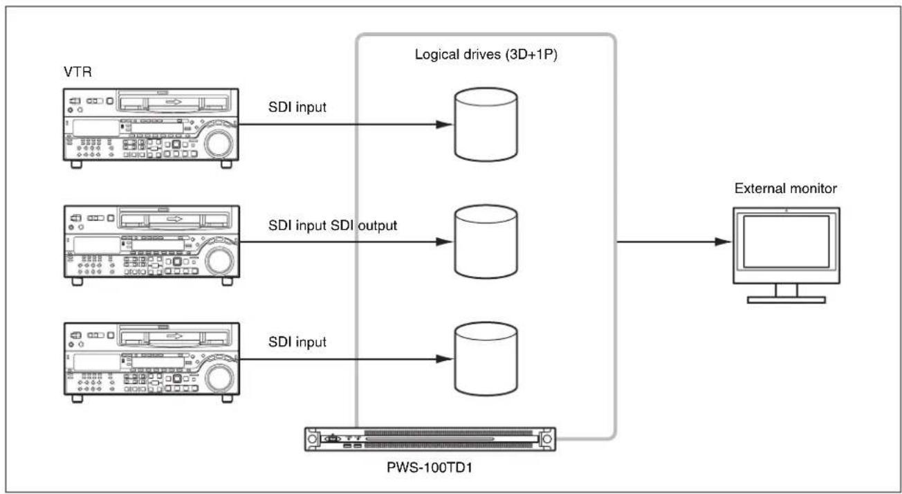
3 inputs/1 output
Connect VTRs to the SDI 1 to 3 connectors, and an external monitor to the SDI 4 connector. The external monitor connected to the SDI 4 connector is used to monitor the high-resolution images of clips.
flowchart
graph TD
    A["Operator Operator Manager"] --> B["Gigabit Ethernet"]
    B --> C["VTR"]
    C --> D["HD/SD SDI"]
    C --> E["RS-422"]
    C --> F["HD/SD SDI"]
    C --> G["RS-422"]
    C --> H["HD/SD SDI"]
    C --> I["RS-422"]
    B --> J["PWS-100TD1"]
    J --> K["External monitor"]
    J --> L["HD SDI"]
    J --> M["USB 3.0"]
    J --> N["Drive unit"]
    J --> O["REF IN"]
    J --> P["Sync signal"]
    style A fill:#f9f,stroke:#333
    style B fill:#ccf,stroke:#333
    style C fill:#cfc,stroke:#333
    style D fill:#fcc,stroke:#333
    style E fill:#fcc,stroke:#333
    style F fill:#fcc,stroke:#333
    style G fill:#fcc,stroke:#333
    style H fill:#fcc,stroke:#333
    style I fill:#fcc,stroke:#333
    style J fill:#cff,stroke:#333
    style K fill:#ffc,stroke:#333
    style L fill:#ffc,stroke:#333
    style M fill:#ffc,stroke:#333
    style N fill:#ffc,stroke:#333
    style O fill:#ffc,stroke:#333
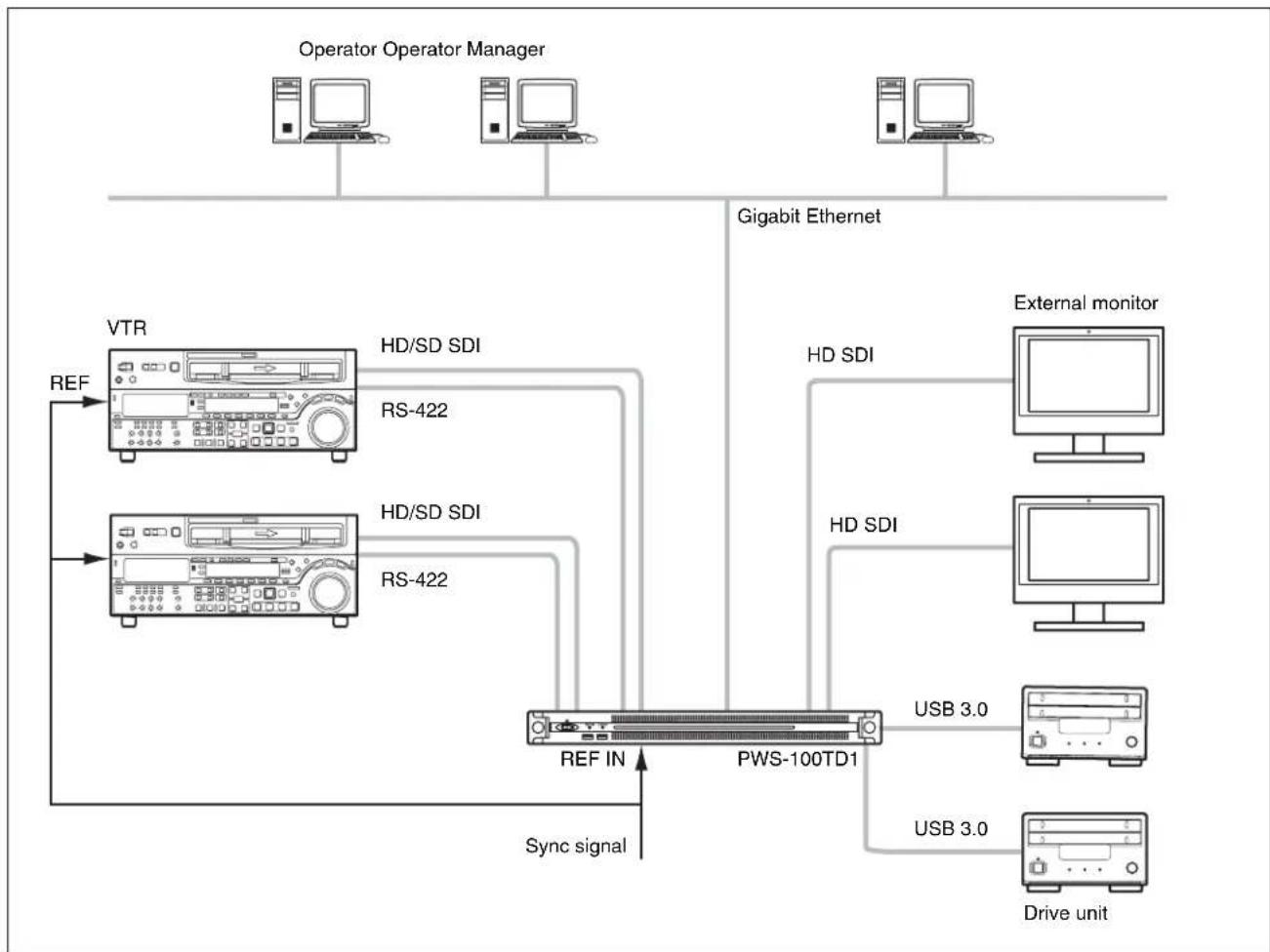
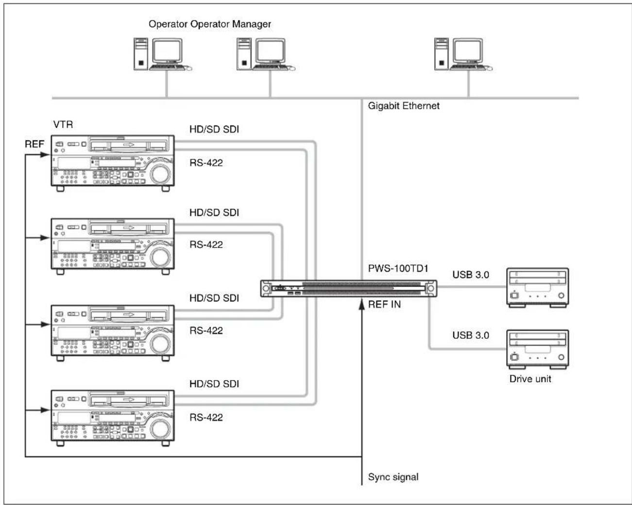
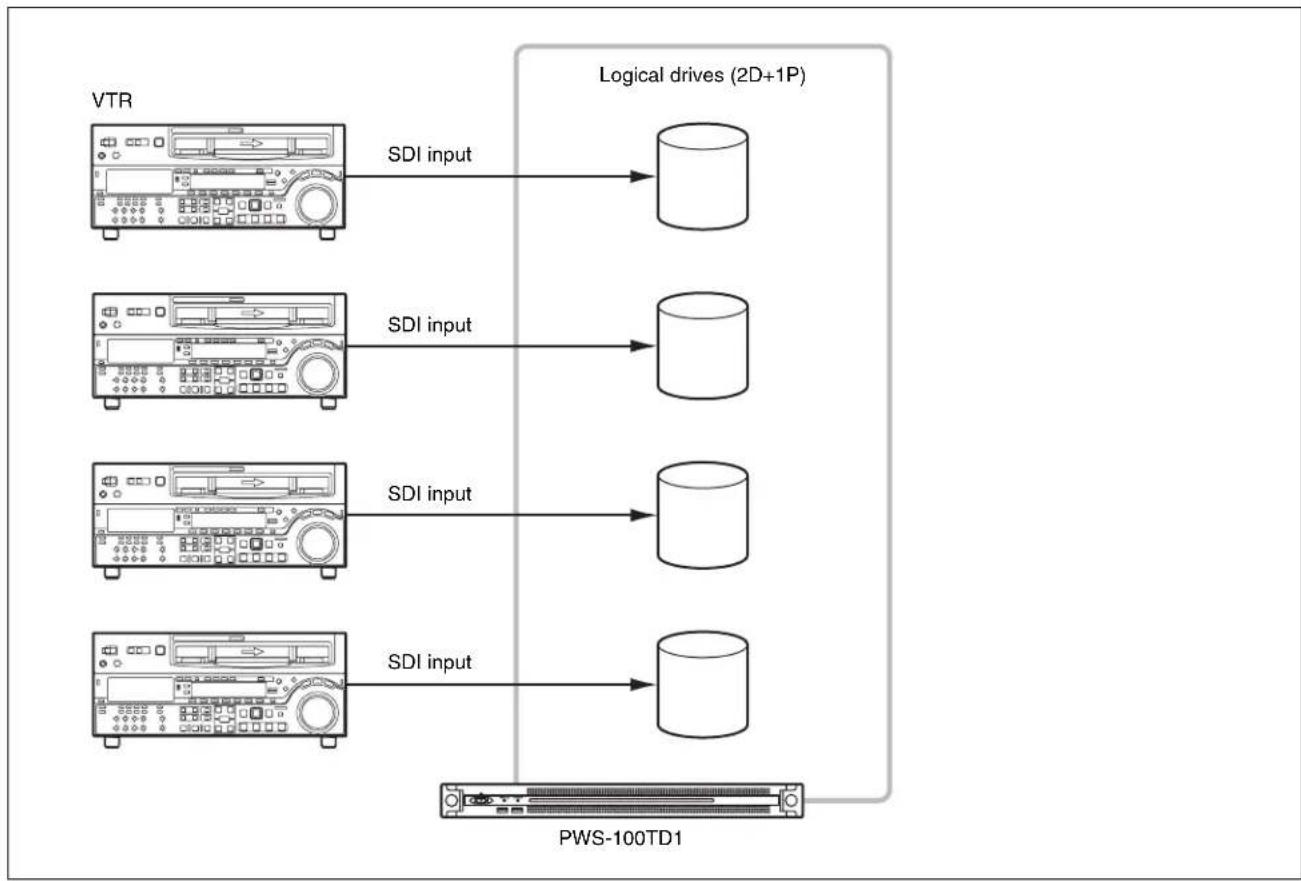
4 inputs
Connect VTRs to the SDI 1 to 4 connectors. When SDI4 is not used for ingesting, you can monitor the high-resolution images of clips in the GUI.
flowchart
graph TD
    A["Operator Operator Manager"] --> B["VTR"]
    A --> C["Gigabit Ethernet"]
    B --> D["REF"]
    D --> E["HD/SD SDI"]
    E --> F["RS-422"]
    F --> G["HD/SD SDI"]
    G --> H["RS-422"]
    H --> I["HD/SD SDI"]
    I --> J["HD/SD SDI"]
    J --> K["RS-422"]
    K --> L["HD/SD SDI"]
    L --> M["RS-422"]
    M --> N["PWS-100TD1"]
    N --> O["USB 3.0"]
    N --> P["USB 3.0"]
    N --> Q["Drive unit"]
    Q --> R["Sync signal"]
    N --> S["REF IN"]
RAID configuration selection
After setting the system configuration, set the RAID configuration so that it has the same number SDI inputs and logical drives as the selected system configuration.
You set the RAID configuration using the PWS-100 maintenance web application. Set up the RAID configuration shown below, according to the selected system configuration. Configurations other than the following are not supported. For details about configuration, refer to the operation manual of the PWS-100 maintenance web application.
- For 2 inputs/2 outputs: (5D + 1P) × 2
- For 3 inputs/1 output: (3D + 1P) × 3
• For 4 inputs: (2D + 1P) × 4
Note
If the RAID configuration is changed, all full-resolution files, proxy files, report files, and work orders written in internal storage are deleted. Before changing the RAID configuration, always transfer or download all data to prevent data loss.
About RAID configuration
The PWS-100TD1 supports the following RAID configurations when a total of 12 HDDs are installed.
- 2D + 1P: Contains a total of four logical drives, where each logical drive contains two data HDDs and one parity HDD.
- 3D + 1P: Contains a total of three logical drives, where each logical drive contains three data HDDs and one parity HDD.
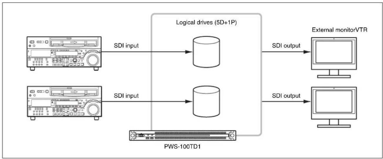
- 5D + 1P: Contains a total of two logical drives, where each logical drive contains five data HDDs and one parity HDD.
For 2 inputs/2 outputs
flowchart
graph LR
    A["SDI input"] --> B["Logical drives (5D+1P)"]
    C["SDI input"] --> D["PWS-100TD1"]
    B --> E["External monitorVTR"]
    D --> F["External monitorVTR"]
    B --> G["SDI output"]
    D --> H["SDI output"]
For 3 inputs/1 output
flowchart
graph LR
    A["VTR"] -->|SDI input| B["Logical drives (3D+1P)"]
    C["VTR"] -->|SDI input SDI output| D["Logical drives (3D+1P)"]
    E["VTR"] -->|SDI input| F["PWS-100TD1"]
    B --> G["External monitor"]
    D --> G
    F --> G
    G --> H["Computer"]
For 4 inputs
flowchart
graph LR
    A["VTR"] -->|SDI input| B["Logical drives (2D+1P)"]
    C["VTR"] -->|SDI input| D["Logical drives (2D+1P)"]
    E["VTR"] -->|SDI input| F["Logical drives (2D+1P)"]
    G["VTR"] -->|SDI input| H["Logical drives (2D+1P)"]
    I["PWS-100TD1"] --> J["Logical drives (2D+1P)"]
    style A fill:#f9f,stroke:#333
    style C fill:#f9f,stroke:#333
    style E fill:#f9f,stroke:#333
    style G fill:#f9f,stroke:#333
    style I fill:#ccf,stroke:#333
    style B fill:#cfc,stroke:#333
    style D fill:#cfc,stroke:#333
    style F fill:#cfc,stroke:#333
    style H fill:#cfc,stroke:#333
    style J fill:#fcc,stroke:#333
Supported Devices
Operation with the following devices has been certified.
Supported VTRs
Operation with the following VTRs has been certified.
| Betacam SP BVW-75 | BVW-75P |
| Digital Betacam DVW-A500 | DVW-A500P |
| Betacam SX DNW-A75 | DNW-A75P |
| IMX MSW-M2000 | MSW-M2000P |
| DVCAM DSR-2000 | DSR-2000P |
| HDCAM HDW-M2000 | HDW-M2000P |
Supported ODS Drives
Operation with the following ODS drives has been certified.
- ODS-D55U
- ODS-D77U
- ODS-D280U
Name and Function of Parts
Front View
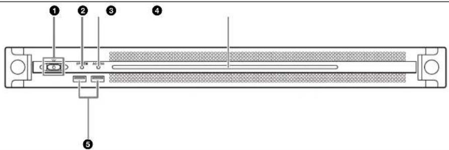
①On/Standby button and indicator
Switches the unit on/off (standby state). Connecting the power cord places the unit in standby state, and the indicator turns on red. Pressing the On/Standby button while in standby state turns on the unit and the indicator turns on green. Pressing and holding the On/Standby button for two seconds switches the unit to standby state, and the indicator changes to red. To turn the unit on again after switching from On state to standby state, when the indicator is red, press and hold the On/Standby button for three seconds or longer. The indicator goes out when the power cord is disconnected.
② SYSTEM indicator
Indicates the status of the unit.
Green: Operating normally
Flashing green (once per second): System is booting or transitioning to standby state.
Flashing orange (once per second): A warning has been generated.
High-speed flashing red (four times per second): An error has occurred.
③ACCESS indicator
Indicates the access status to storage.
Off: Not accessing storage
Blue: Accessing storage
④Front panel LED
Turns on according to settings in the web application. The LED is configured using [001: LINE LED] in the [Settings] page on the Maintenance screen.
⑤USB connectors (front panel)
Connects to a keyboard and mouse for initializing the unit. USB devices not described in this document are not supported.
Note
Both USB ports on the front panel support power delivery (900 mA).
Front View (Panel Removed)
When the SYSTEM indicator or web application indicates an error, you can remove the front panel to check the status of the hardware components.
To remove the front panel, loosen the screws on the left and right sides and pull the panel towards you.
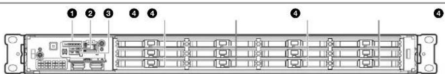
①FAN indicators
If any of the fans fail, the corresponding fan indicator turns on red.
②POWER indicators
If either of the AC power supply units fail, the corresponding indicator turns on red.
③TEMP indicator
If an abnormally high temperature is detected within the unit, the indicator turns on red.
④HDD status indicators
If a warning is generated for an HDD, the corresponding indicator turns on red. The indicator turns off if the corresponding HDD fails, is in sleep state, or has been removed.
Rear View
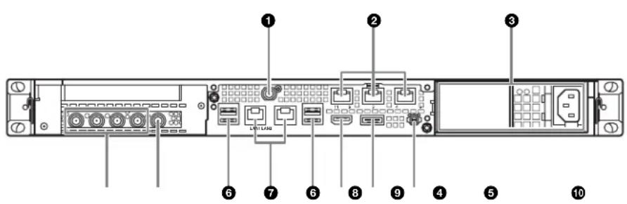
① SYSTEM TC connector
Not used by this system.
② Remote connectors (1/2, 3/4, 5)
Connect VTR devices to the Remote 1/2 and Remote 3/4 connectors, using the RJ-45 D-sub conversion cable (supplied) and commercially-available 9-pin remote cables, for VTR remote control operation. You can connect two VTRs using a single RJ-45 D-sub conversion cable and two 9-pin remote cables.
The Remote 5 connector is not used by this system.
③AC power supply units
Insert the power cords and connect to power outlets. Only one AC power supply unit is installed at the factory. A second optional power supply unit can be installed to provide power supply redundancy. When used in systems that require reliability, power supply redundancy allows the unit to continue operating even if a power supply unit fails.
For details about installing or replacing a power supply unit, consult your Sony sales or service representative.
④SDI (1 to 4) connectors
SDI1 to SDI4 connectors are numbered from left to right. Connect to a VTR device or external monitor, using an SDI cable, to input/output SDI signals.
⑤REF IN connector
Input a sync reference signal.
⑥USB connectors (rear panel)
Connect to drive units using USB cables. USB devices not described in this document are not supported.
Notes
- Of the four USB connectors on the rear panel, only the bottom right port supports power delivery (900 mA). The other three ports do not support power delivery, and should be used to connect USB devices that do not require power supplied from the USB connector.
- Use SuperSpeed USB cables.
⑦ LAN connectors
Connect to a Gigabit Ethernet network.
⑧HDMI connector
Connect to a monitor using an HDMI cable. Use an HDMI cable that conforms to the following standard.
• High Speed HDMI Cable (Premium High Speed HDMI Cable)
⑨DisplayPort connector
Connect to a monitor using a DisplayPort-to-DVI converter cable or DisplayPort-to-HDMI converter cable. Use an active-type converter cable.
Note
Use a DisplayPort cable that conforms to the following standard. •DP v1.2a (compliant)
10 Ground terminal
Connect to ground.
Setting Up
Initial Settings
Before using the unit, configure the Windows settings within the unit. The description below describes the standard settings in Windows 8.
Note
To reboot the unit, first shut down the unit and then turn the On/Standby button on the front panel on again, without rebooting Windows.
1 Connect a keyboard and mouse to the USB connectors on the front panel, and connect a monitor to the DisplayPort connector or HDMI connector on the rear panel.
2 Set the On/Standby button to the On position.
3 When the Windows login screen appears, enter "tds" as the user name, enter "tds" as the password, and log in.
Setting the Windows interface language
1 Hold down the Windows key and press the X key, then select [Control Panel] from the displayed menu.
2 Select [Clock, Language, and Region] > [Language].
3 Select [Add language] to add a language.
4 Select the language to add, then click [Add].
5 Select the language to use and click [Move up] until the language is displayed at the top.
6 Sign out and then sign in again.
Configuring the network
1 Connect a LAN cable to the LAN connector on the rear panel of the unit, and connect the other end to the network.
2 Click [View network status and tasks] under [Network and Internet] in the control panel.
3 Click [Connections] > [LAN 1/2].
4 Click the [Properties] button.
5 Select [Internet Protocol Version 4 (TCP/IPv4)], then click the [Properties] button.
6 Change the IP address and other settings.
7 Click the [Advanced] button to configure DNS, WINS, and other settings.
8 When finished, click the [OK] button.
Setting the date and time
1 Select [Set the time and date] under [Date and Time] in the [Clock, Language, and Region] control panel.
2 Click [Change time zone] on the [Date and Time] tab, and select the time zone.
3 Click [Change date and time] on the [Date and Time] tab, and set the date and time.
4 Click the [Change settings] button on the [Internet Time] tab.
5 Specify an NTP server, then click the [Update Now] button.
6 Place a check mark in [Synchronize with an Internet time server] to periodically correct the clock using the NTP server.
Setting user passwords
The default user “tds” is configured for Windows within the unit. Set the password for the user to provide security.
1 Click [User Accounts and Family Safety] in the control panel.
2 Click [User Account] > [Change account type].
3 Select the "tds" user.
4 Click [Change the password].
5 Enter a new password and a password hint, then click the [Change Password] button.
Setting the service password
When setting/modifying the “tds” user password, set the service password as follows.
1 Double-click [Services] under [Administrative tools] in the [System and Security] control panel.
2 Right-click "Apache Tomcat 7.0 Tomcat7" in the Services list and select [Properties].
3 Open the [Log On] tab.
4 Click [This account], enter “.\tds” and then enter a password for user “tds” under [Password].
5 Click the [Apply] button, then click [OK] to close the dialog.
6 Select "Sony Ingest Service" in the Services list, and repeats steps 2 to 5.
Adding a user
You can add new users to Windows.
1 Click [User Accounts and Family Safety] in the control panel.
2 Click [User Accounts] > [Change account type].
3 Click [Add a new user in PC settings].
4 Click [Add a user].
5 Enter a user name, password, and password hint, then click [Next].
6 Click [Finish]. Next, change the account type.
7 Click [Change account type] under [User Accounts and Family Safety] in the control panel.
8 Select the user whose account type you want to change.
9 Click [Change the account type].
10 Select [Standard] or [Administrator], then click the [Change account type] button.
Changing the computer name
The PWS-100TD1 uses the computer name as part of the https communications authentication. To change the computer name, use the following procedure. A new certificate will be generated. After the computer name is changed, re-import the new certificate on the client PC.
1 Select [System and Security] > [System] in [Control Panel].
2 Click [Computer name] > [Change Settings].
3 Click the [Change] button on the [Computer name] tab of the [System Properties] dialog.
4 Change the computer name, then click [OK].
5 Restart the computer when prompted to restart.
6 Sign in to the PWS-100TD1 unit again.
7 Open Command Prompt as an administrator, and enter the following commands.
cd C:\Program Files\Sony\TapeDigitize\DIG\script keystore.bat
8 Restart the system.
9 Re-import the certificate as described in "Installing Certificates" (page 31).
Signing out
When finished, sign out from Windows.
1 Move the mouse cursor to the top right corner of the screen to display the Charms bar, then click [Start].
2 Click the account name on the top right of the screen, then click [Sign out].
Displaying the Web Application
You connect to the unit via the network from a client PC and use the web application in a web browser on the client PC to control and configure the unit.
Recommended client PC environment
CPU: Core i5 3 GHz or higher
Memory: 4 GB or higher
OS: Windows 7 Pro 32/64-bit Windows 8/8.1 Pro 32/64-bit Mac OS X 10.8/10.9
Web browser: Google Chrome 40 or later (update to the latest version)
Display resolution: 1366 × 768 pixels or higher
Connect a computer satisfying the above conditions to the LAN 1 or LAN 2 connector on the rear panel of the unit. Enter “https://(IP_address):8443/tds or https://pws-100
Enter the user name and password when the login screen appears.
The following user name and password are configured by default.
User name: admin
Password: tds
System Settings
Configure the system on the Setting screen in the web application.
Log in as a user with administrator privileges when logging in to the web application.
For details about operating the web application, refer to the Help of the application.
Changing the interface language
You can change the interface language of the web application.
Select the language in [Language] on the [My Settings] page of the Setting screen.
Operation frequency selection
Select the operation frequency of the system. You select the frequency under [Ingest Settings] on the [Ingest] page of the Setting screen.
Adding users
To add user accounts in addition to the default admin account, add new users on the [Users] page of the Setting screen.
Registering a transfer destination
To transfer ingested clips to a cartridge or network server, register the transfer destination on the [Transfer] page of the Setting screen.
Installing Certificates
Displaying the web application using an https connection from a web browser may display an error message, such as "The site's security certificate is not trusted!". To connect successfully via https without an error, a root CA certificate (client certificate) corresponding to the server (PWS-100-
The following describes the procedure for installing a certificate using Google Chrome.
Root CA certificate installation procedure
1 Access the web application using https in a web browser.
An error message, such as “The site’s security certificate is not trusted!” appears.
2 Click the lock icon on the left hand end of the address bar.
3 Click [Certificate information] in the popup window.
The [Certificate] dialog appears. Make a note of the certificate issuer "PWS-100-
4 Click the [Details] tab, then click the [Copy to File] button.
The Certificate Export Wizard appears.
5 Click [Next].
6 Select "DER encoded binary X.509 (.CER)," then click [Next].
7 Click the [Browse] button and specify a folder in which to store the certificate, then click [Next].
Exporting of the certificate commences.
8 When the export wizard completion window appears, click [Finish].
9 When the message window appears, click [OK].
10 Click the Chrome menu button, then select [Settings] from the menu.
11 Click [Show advanced settings] on the Settings screen, then click the [Manage certificates] button under [HTTP/SSL].
The [Certificate] dialog appears.
12 Click the [Trusted Root Certification Authorities] tab of the dialog, then click the [Import] button.
The Certificate Import Wizard appears.
13 Click [Next].
14 Click the [Browse] button and select the downloaded file, then click [Next].
15 Check that [Place all certificates in the following store] is selected and that “Trusted Root Certification Authorities” is displayed in [Certificate store:], then click [Next].
Importing of the certificate commences.
16 When the import wizard completion window appears, click [Finish].
The wizard exits.
17 When the message window appears, click [OK].
18 Click the Chrome menu button and select [Exit] from the menu. Then, relaunch Chrome.
19 Configure name resolution settings so that the issuer "PWS-100-
Library Licenses
Refer to the [Help] menu in the web application for the licenses of each type of library used by the PWS-100TD1.
Maintenance Web Application Operation
For details about the operation of the Maintenance Web Application for system administrators, log in to the unit and click the shortcut icon on the desktop to refer to the Operation Manual.
Usage Precautions
Precautions for products with built-in HDD
This unit has a built-in hard disk drive (HDD). The HDD is a precision device. If subject to shock, vibration, static electricity, high temperature or humidity, data loss can occur. When installing and using the unit, closely observe the following precautions.
Protect from shocks and vibrations
When subject to shocks or vibrations, the HDD can be damaged and loss of data on the HDD can occur.
- When transporting the unit, use the specified packing material. When transporting on a dolly or similar, use a type which does not transmit excessive vibrations. Excessive shocks and vibrations can damage the HDD.
- Never move the unit while it is powered.
- Do not remove panels or outer parts of the unit.
- When placing the unit on a floor or other surface, place on a level, stable surface.
- Do not place the unit near other devices that may become a source of vibrations.
- When moving the unit, always turn the power supply off.
Wait for 30 seconds after turning power off
For a brief interval after the power is turned off, the platters inside the HDD will still keep spinning and the heads will be in an insecure position. During this interval, the unit is more susceptible to shocks and vibrations than during normal operation. For a period of at least 30 seconds after turning power off, avoid subjecting the unit even to very light shocks. After this period, the hard disk will be fully stopped and the unit can be manipulated.
Temperature and humidity related precautions
Use and store the unit only in locations where the specified temperature and humidity ranges are not exceeded. (Be sure to use the unit that conforms fully to the specifications of this unit.)
When HDD seems to be faulty
Even if the HDD is showing signs of malfunction, be sure to observe all the above precautions. This will prevent further damage from occurring until the problem can be diagnosed and corrected.
Replacement of the HDD and other consumable parts
The HDD and battery are consumable parts that will need periodic replacement.
When operating at room temperature, a normal replacement cycle will be about 2 to 5 years.
However, this replacement cycle represents only a general guideline and does not imply that the life expectancy of these parts is guaranteed. For details on parts replacement, contact your dealer.
For details about the replacement cycle, contact your Sony sales or service representative.
Power supply precautions
If the unit is suddenly turned off during operation, data loss may occur. To maintain data integrity, the use of an uninterruptible power supply (UPS) is recommended.
To disconnect the power cord or turn off the breaker, always press the On/Standby button on the unit to stop the unit before proceeding.
USB device precautions
When using the unit when connected to a self-powered USB device (such as the ODS-D77U), the device may not be recognized, depending on the timing of when the device is turned on. If this occurs, turn the USB device off and on again, or disconnect and reconnect the USB cable.
Network precautions
Depending on the operating environment, unauthorized third parties on the network may be able to access the system.
We strongly recommend configuring all of the passwords for security purposes.
Configure all the passwords following the procedure on page29.
From a safety standpoint, when using the unit connected with the network, it is strongly recommended to access the Control window via a Web browser and change the access limitation settings from the factory preset values (page30).
Changing the password regularly is also recommended.
Do not browse any other website in the Web browser while making settings or after making settings. Since the login status remains in the Web browser, close the Web browser when you complete the settings to prevent unauthorized third parties from using the unit or harmful programs from running.
Specifications
General
Power requirement
100 V to 240 V AC
50/60 Hz
Power consumption
235 W
Standby power consumption
3 W or lower
Operating temperature
5^ to 35^ (41°F to 95°F)
Storage temperature
-20^ to +60^ (-4^ to +140^)
Operating humidity
20% to 90% (relative humidity)
Storage humidity
5% to 80%
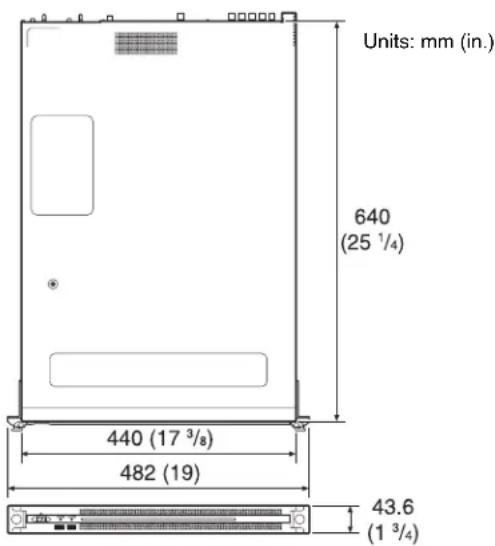
Mass 14 kg (30 lb. 14 oz.)
Dimensions 440 × 43.6 × 640 mm (17^3/8 × 1^3/4 × 25^1/_4 in.) (width / height / depth)
CPU
Processor Intel Core i7 6700TE (2.4 GHz)
Memory 8 GBytes
SO-DIMM (DDR4) (2)
Drive (M.2) 120 GBytes
Drives (HDD) 2.5-inch, 500 GBytes (12)
Expansion bus PCIe Gen2 8Lane (30 W) (2)
Inputs/outputs
LAN RJ-45 (2)
1000BASE-T
100BASE-TX
USB (front panel/rear panel)
Super Speed USB (USB 3.0) Type A (6, 2 on front and 4 on rear)
Front: Power delivery support (900 mA/port)
Rear: Power delivery support on bottom right port (900 mA), not supported on other three ports
HDMI Type A (1)
HDMI Ver. 1.4a, 1920 × 1200 maximum resolution, 60 Hz
DisplayPort DisplayPort (1)
DisplayPort Ver. 1.1a, 2560 × 1600 maximum resolution, 60 Hz
Remote RJ-45 (3)
Sony VTR Protocol (9-pin) compatible, requires RJ-45 to D-sub conversion cable (supplied)
REF IN BNC (1)
SMPTE ST 318 compliant, HD tri-level sync (0.6 Vp-p, 75 Ω, sync positive/negative) or SD black burst/composite sync
(NTSC: 0.286 Vp-p, 75 Ω, sync negative
PAL: 0.3 Vp-p, 75 Ω, sync negative)
SDI 1 to 4 BNC (4)
HD: SMPTE ST 292-1 compliant
SD: SMPTE ST 259 compliant
Supported formats
| Codec Operation frequency | Resolution No. of quantization bits | Audio channels | |
| IMX 30M, 40M, 50M UNCOMPRESS 220M | 59.94i 720 × | 576 422 8-bit | 8ch (16-bit) 4ch (24-bit) |
| 50i 720 × 480 | 422 8-bit | 8ch (16-bit) 4ch (24-bit) | |
| MPEG HD 50M | 59.94i, 50i, 29.97P, 25P, 23.98P | 1920 × 1080 422 8-bit | 8ch (24-bit) |
| MPEG HD 35M | 59.94i, 50i, 29.97P, 25P, 23.98P | 1920 × 1080 420 8-bit | 4ch (16-bit) |
| 1440 × 1080 420 8-bit | |||
| XAVC-I 100M | 59.94i, 50i, 29.97P, 25P, 23.98P | 1920 × 1080 422 10-bit | 8ch (24-bit) |
Recording Time for Each RAID Configuration
The available recording time for each RAID configuration and video codec is given below.
| RAID configuration | 2D + 1P | 3D + 1P | 5D + 1P | ||
| Number of logical drives | 4 | 3 | 2 | ||
| Drive capacity a)(per logical drive) | 838 GB | 1,230 GB | 2,050 GB | ||
| SD | IMX30 Mbps | Per drive | Approx.50 hours | Approx.75 hours | Approx.125 hours |
| Total for all drives | Approx.200 hours | Approx.225 hours | Approx.250 hours | ||
| IMX40 Mbps | Per drive | Approx.35 hours | Approx.55 hours | Approx.95 hours | |
| Total for all drives | Approx.140 hours | Approx.165 hours | Approx.190 hours | ||
| IMX50 Mbps | Per drive | Approx.30 hours | Approx.45 hours | Approx.70 hours | |
| Total for all drives | Approx.120 hours | Approx.135 hours | Approx.140 hours | ||
| UNCOM-PRESS220 Mbps | Per drive | Approx.7 hours | Approx.10 hours | Approx.18 hours | |
| Total for all drives | Approx.28 hours | Approx.30 hours | Approx.36 hours | ||
| HD | MPEG35 Mbps | Per drive | Approx.45 hours | Approx.70 hours | Approx.120 hours |
| Total for all drives | Approx.180 hours | Approx.210 hours | Approx.240 hours | ||
| MPEG50 Mbps | Per drive | Approx.30 hours | Approx.45 hours | Approx.75 hours | |
| Total for all drives | Approx.120 hours | Approx.135 hours | Approx.150 hours | ||
| XAVC100 Mbps | Per drive | Approx.15 hours | Approx.25 hours | Approx.40 hours | |
| Total for all drives | Approx.60 hours | Approx.75 hours | Approx.80 hours | ||
a) Capacity displayed in the GUI.
Note
The achievable recording time may differ from the values above, depending on the recording media and other conditions.
Supplied accessories
RJ-45 to D-sub conversion cable
Part No. 1-848-424-12 (SONY) (2)
Optional accessories
PWSK-101 Optional Power Supply
Design and specifications are subject to change without notice.
SONY WILL NOT BE LIABLE FOR DAMAGES OF ANY KIND RESULTING FROM A FAILURE TO IMPLEMENT PROPER SECURITY MEASURES ON TRANSMISSION DEVICES, UNAVOIDABLE DATA LEAKS RESULTING FROM TRANSMISSION SPECIFICATIONS, OR SECURITY PROBLEMS OF ANY KIND.
Notes
• Always make a test recording, and verify that it was recorded successfully.
SONY WILL NOT BE LIABLE FOR DAMAGES OF ANY KIND INCLUDING, BUT NOT LIMITED TO, COMPENSATION OR REIMBURSEMENT ON ACCOUNT OF FAILURE OF THIS UNIT OR ITS RECORDING MEDIA, EXTERNAL STORAGE SYSTEMS OR ANY OTHER MEDIA OR STORAGE SYSTEMS TO RECORD CONTENT OF ANY TYPE.
• Always verify that the unit is operating properly before use. SONY WILL NOT BE LIABLE FOR DAMAGES OF ANY KIND INCLUDING, BUT NOT LIMITED TO, COMPENSATION OR REIMBURSEMENT ON ACCOUNT OF THE LOSS OF PRESENT OR PROSPECTIVE PROFITS DUE TO FAILURE OF THIS UNIT, EITHER DURING THE WARRANTY PERIOD OR AFTER EXPIRATION OF THE WARRANTY, OR FOR ANY OTHER REASON WHATSOEVER.
- SONY WILL NOT BE LIABLE FOR CLAIMS OF ANY KIND MADE BY USERS OF THIS UNIT OR MADE BY THIRD PARTIES.
- SONY WILL NOT BE LIABLE FOR THE LOSS, REPAIR, OR REPRODUCTION OF ANY DATA RECORDED ON THE INTERNAL STORAGE SYSTEM, RECORDING MEDIA, EXTERNAL STORAGE SYSTEMS OR ANY OTHER MEDIA OR STORAGE SYSTEMS.
-
SONY WILL NOT BE LIABLE FOR THE TERMINATION OR DISCONTINUATION OF ANY SERVICES RELATED TO THIS UNIT THAT MAY RESULT DUE TO CIRCUMSTANCES OF ANY KIND.
-
Windows is a registered trademark of Microsoft Corporation in the United States and other countries.
- Google Chrome is a trademark or registered trademark of Google Inc.
Other products or system names appearing in this document are trademarks or registered trademarks of their respective owners. Further, the ®, or ™ symbols are not used in the text.
This product uses the T-Kernel 2.0 source code based on the T-License 2.0 from the T-Engine Forum (www.t-engine.org).
For the customers in Taiwan
警告使用者:
①Indicateurs FAN
PCIe Gen2 8Lane (30 W) (2)
Entrées/sorties
LAN RJ-45 (2)
1000BASE-T
100BASE-TX
①FAN-LEDs
PCIe Gen2 8Lane (30 W) (2)
Eingänge/Ausgänge
LAN RJ-45 (2)
1000BASE-T
100BASE-TX
①Indicatori FAN
①Indicadores FAN
①Conector SYSTEM TC
PCIe Gen2 8Lane (30 W) (2)
Entradas/salidas
LAN RJ-45 (2)
1000BASE-T
100BASE-TX
USB (panel frontal/panel posterior)
①开机 / 待机键和指示灯
① SYSTEM TC 接口
本系统未使用。
①FAN 표시등
① SYSTEM TC 커넥터
이 시스템에서는 사용되지 않습니다.
DisplayPort 버전.1.1a,
The material contained in this manual consists of information that is the property of Sony Corporation and is intended solely for use by the purchasers of the equipment described in this manual.
Sony Corporation expressly prohibits the duplication of any portion of this manual or the use thereof for any purpose other than the operation or maintenance of the equipment described in this manual without the express written permission of Sony Corporation.


