
PWS-110RX1A - Audio/video converter SONY - Free user manual and instructions
Find the device manual for free PWS-110RX1A SONY in PDF.

| Product type | Audio/video converter for streaming (receiver/connection manager) |
| Brand / Model | Sony / PWS-110RX1A |
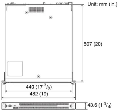
| Dimensions (W × H × D) | 440 × 43.6 × 507 mm |
| Weight | 9.8 kg |
| Power supply | 100–240 V AC, 50/60 Hz, 235 W (standby ≤ 3 W) |
| Processor | Intel Core i7‑6700TE (2.4 GHz) |
| Memory | 8 GB SO‑DIMM DDR4 (2 slots) |
| Internal storage | 128 GB / 256 GB M.2 |
| SDI video outputs | 4 BNC connectors (SMPTE ST 292‑1 HD) |
| Reference input (REF IN) | 1 BNC: HD tri‑level sync or SD black burst |
| Network connectors | 2 RJ‑45 (1000BASE‑T / 100BASE‑TX) |
| USB ports | 6 × USB 3.0 Type A (2 front + 4 rear); front 900 mA/port, rear 1 port 900 mA |
| HDMI output | 1 × Type A (HDMI 1.4a, max 1920×1200 @ 60 Hz) |
| Main functions | Receiving video streams from network camcorders, SDI output, connection management via web interface |
| Operating temperature | 5 °C to 35 °C (41 °F to 95 °F) |
| Operating humidity | 20 % to 90 % RH |
| Safety – Power supply | Use an uninterruptible power supply (UPS); do not shut down abruptly |
| Maintenance – Consumable parts | Fan and battery: replace every 2 to 5 years (contact Sony support) |
| Supplied accessories | User manual, operation guide, 4 rack mount screws |
| Option | Redundant power supply PWSK‑101 |
Frequently Asked Questions - PWS-110RX1A SONY
User questions about PWS-110RX1A SONY
0 question about this device. Answer the ones you know or ask your own.
Ask a new question about this device
Download the instructions for your Audio/video converter in PDF format for free! Find your manual PWS-110RX1A - SONY and take your electronic device back in hand. On this page are published all the documents necessary for the use of your device. PWS-110RX1A by SONY.
USER MANUAL PWS-110RX1A SONY
Japanese/English/French/German/Italian/Spanish/Chinese/Korean
1st Edition (Revised 2)

目次
概要 3
システム構成例 4
各部の名称と働き 5
前面 5
前面(パネルを外した場合)……5
背面 6
準備 7
初期設定....7
①FAN インジケーター
10
① SYSTEM TC 端子
本システムでは使用しません。
Name and Function of Parts.... 14
Front View.... 14
Front View (Panel Removed).... 14
Rear View.... 15
Setting Up 16
Initial Settings.... 16
Application and Camcorder Settings.... 17
Library Licenses 17
Maintenance Web Application Operation 17
Usage Precautions.... 18
Specifications.... 18
For safety, please read the precautions described in the PWS-100/110 Operation Guide (supplied).
Overview
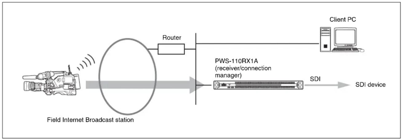
This unit is a system for live streaming on the Internet. It receives streaming video transmitted from a camcorder which has a network function, and outputs SDI signals for live streaming.
The unit is comprised by an RX application that receives streaming video, and a Connection Control Manager that manages the connections between the camcorder and the unit. The Connection Control Manager has a web GUI that can be displayed using a web browser on a client PC, and can be used to manage multiple connections simultaneously.
System Configuration Examples
This section shows live streaming system configuration examples using the PWS-110RX1A.
The following example shows a small-scale system using only one unit. The unit acts as both streaming receiver and connection manager.
flowchart
graph LR
    A["Field Internet Broadcast station"] --> B["Router"]
    B --> C["PWS-110RX1A (receiver/connection manager)"]
    C --> D["SDI device"]
    D --> E["Client PC"]
Additional PWS-110RX1A units acting as streaming receivers can be used.
For streaming transmission, a camcorder connected to a CBK-WA100/101 Wireless Adaptor or a camcorder with wireless function is required. For details about supported camcorders, consult your Sony sales or service representative.
Name and Function of Parts
Front View
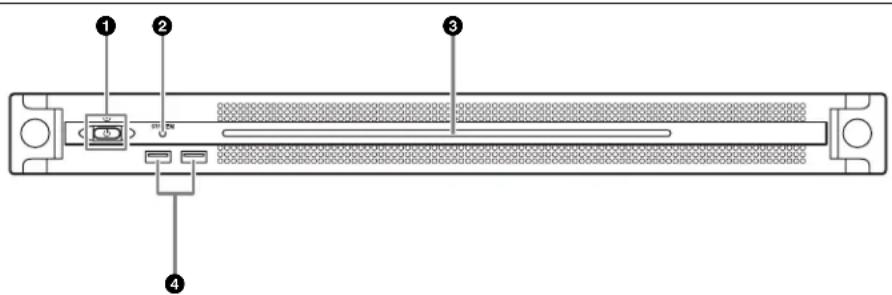
①On/Standby button and indicator
Switches the unit on/off (standby state). Connecting the power cord places the unit in standby state, and the indicator turns on red. Pressing the On/Standby button while in standby state turns on the unit and the indicator turns on green. Pressing and holding the On/Standby button for two seconds switches the unit to standby state, and the indicator changes to red. To turn the unit on again after switching from On state to standby state, when the indicator is red, press and hold the On/Standby button for three seconds or longer. The indicator goes out when the power cord is disconnected.
② SYSTEM indicator
Indicates the status of the unit.
Lit green: Operating normally
Flashing green (once per second): System is booting or transitioning to standby state
Flashing orange (once per second): A warning has been generated.
High-speed flashing red (four times per second): An error has occurred.
③Front panel LED
Turns on according to settings in the web GUI. The LED is configured using [001: LINE LED] in the [Settings] page on the Maintenance screen.
④USB connectors (front panel)
Connects to a keyboard and mouse for initializing the unit. USB devices not described in this document are not supported.
Notes
- Both USB ports on the front panel support power delivery (900 mA).
- Use SuperSpeed USB cables.
Front View (Panel Removed)
When the SYSTEM indicator or web GUI indicates an error, you can remove the front panel to check the status of the hardware components.
To remove the front panel, loosen the screws on the left and right sides and pull the panel towards you.
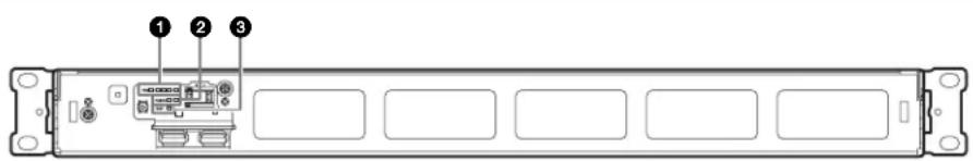
①FAN indicators
If any of the fans fail, the corresponding fan indicator turns on red.
② POWER indicators
If either of the AC power supply units fail, the corresponding indicator turns on red.
③TEMP indicator
If an abnormally high temperature is detected within the unit, the indicator turns on red.
Rear View
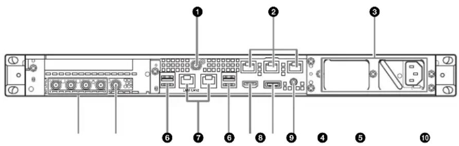
① SYSTEM TC connector
Not used by this system.
② Remote connectors (1/2, 3/4, 5)
Not used by this system.
③AC power supply units
Insert the power cords and connect to power outlets. Only one AC power supply unit is installed at the factory. A second power supply unit can be installed to provide power supply redundancy. When used in systems that require reliability, power supply redundancy allows the unit to continue operating even if a power supply unit fails.
For details about installing or replacing a power supply unit, consult your Sony sales or service representative.
④SDI (1 to 4) connectors
SDI1 to SDI4 connectors are numbered from left to right. Outputs SDI signals.
⑤REF IN connectors
Input sync reference signals.
⑥USB connectors (rear panel)
Connect to a keyboard and mouse. USB devices not described in this document are not supported.
Notes
- Of the four USB connectors on the rear panel, only the bottom right port supports power delivery (900 mA). The other three ports do not support power delivery, and should be used to connect USB devices that do not require power supplied from the USB connector.
- Use SuperSpeed USB cables.
⑦ LAN connectors
Connect to LAN cables.
⑧HDMI connector
Connect to a monitor using an HDMI cable. Use an HDMI cable that conforms to the following standard. • High Speed HDMI Cable (Premium High Speed HDMI Cable)
⑨DisplayPort connector
Not used by this system.
⑩Ground terminal
Connect to ground.
Setting Up
Initial Settings
Before using the unit, configure the Windows settings within the unit. The description below describes the settings in Windows 10.
Note
To reboot the unit, first shut down the unit and then turn the On/Standby button on the front panel on again, without rebooting Windows.
1 Connect a keyboard and mouse to the USB connectors on the front panel, and connect a monitor to the HDMI connector on the rear panel.
2 Set the On/Standby button to the On position.
3 When the Windows sign-in screen appears, enter "rx1" as the user name, enter "rx1" as the password, and sign in.
4 When the password setup screen appears, configure a new password and sign in.
The "rx1" default user is configured for Windows within the unit. Set the password for the user to provide security.
Setting the Windows interface language
1 Hold down the Windows key and press the X key, then select [Control Panel] from the displayed menu.
2 Select [Clock, Language, and Region] > [Language].
3 Select [Add language] to add a language.
4 Select the language to add, then click [Add].
5 Select the language to use and click [Move up] until the language is displayed at the top.
6 Sign out and then sign in again.
Configuring the network
1 Connect a LAN cable to the LAN1 connector on the rear panel of the unit. Connection and network settings for the user environment are required.
2 Click [View network status and tasks] under [Network and Internet] in the control panel.
3 Click the device connected by the LAN cable in [Connections].
4 Click the [Properties] button.
5 Select [Internet Protocol Version 4 (TCP/IPv4)], then click the [Properties] button.
6 Change the IP address and other settings.
7 Click the [Advanced] button to configure DNS, and other settings.
8 When finished, click the [OK] button.
Setting the date and time
1 Select [Set the time and date] under [Date and Time] in the [Clock, Language, and Region] control panel.
2 Click [Change time zone] on the [Date and Time] tab, and select the time zone.
3 Click [Change date and time] on the [Date and Time] tab, and set the date and time.
4 Click the [Change settings] button on the [Internet Time] tab.
5 Specify an NTP server, then click the [Update Now] button.
6 Place a check mark in [Synchronize with an Internet time server] to periodically correct the clock using the NTP server.
Signing out
When finished, sign out from Windows.
1 Click [Start].
2 Click the account name displayed at the top of the Start menu, then click [Sign out].
Application and Camcorder Settings
After configuring Windows, configure the application and camcorder settings using the following procedures. For details about configuration, refer to the Help of the system.
①Connection Control Manager settings
Display and configure the Connection Control Manager admin screen from a client PC.
②RX application settings
Launch the Initialization Tool to configure the RX (receiver) application.
③ Camcorder transmitter settings
Configure the camcorder transmitter or the wireless adaptor connected to the camcorder.
For details about configuration, access the following URL and refer to the Help of the system.
http://helpguide.sony.net/pro/rx/v1/en/index.html

Library Licenses
You can display license information about each type of library used by the PWS-110RX1A from [Help] on the Connection Control Manager admin screen.
Maintenance Web Application Operation
For details about the operation of the Maintenance Web Application for system administrators, sign in to the unit and double-click the desktop shortcut to browse the manual.
Usage Precautions
Power supply precautions
If the unit is suddenly turned off during operation, data loss may occur. To maintain data integrity, the use of an uninterruptible power supply (UPS) is recommended. To disconnect the power cord or turn off the breaker, always press the On/Standby button on the unit to stop the unit before proceeding.
Components with limited lifespan
The fan and battery are consumable parts that will need periodic replacement. When operating at room temperature, a normal replacement cycle will be about 2 to 5 years. However, this replacement cycle represents only a general guideline and does not imply that the life expectancy of these parts is guaranteed. For details on parts replacement, contact your dealer.
Network precautions
Depending on the operating environment, unauthorized third parties on the network may be able to access the system. We strongly recommend configuring all of the passwords for security purposes. Configure all the passwords following the procedure on page 16.
USB device precautions
The unit does not support UASP (USB Attached SCSI Protocol).
Specifications
General
Power requirement 100 V to 240 V AC 50/60 Hz
Power consumption 235 W
Standby power consumption 3 W or lower
Operating temperature 5 °C to 35 °C (41 °F to 95 °F)
Storage temperature -20 °C to +60 °C (-4 °F to +140 °F) Operating humidity 20% to 90% (relative humidity)
Storage humidity 5% to 80%
Mass 9.8 kg (21 lb. 9.7 oz.)
Dimensions 440× 43.6× 507mm(17^3 / _8× 1^3 / _4× 20 in.) (width / height / depth)
CPU
Processor Intel Core i7 6700TE (2.4 GHz)
Memory 8 GBytes SO-DIMM (DDR4) (2)
Drive (M.2) 128 GBytes / 256 GBytes
Expansion bus PCIe Gen2 8Lane (30 W) (2)
Inputs/outputs
LAN RJ-45 (2) 1000BASE-T, 100BASE-TX
USB (front panel/rear panel) Super Speed USB (USB 3.0) Type A (6, 2 on front and 4 on rear) Front: Power delivery support (900 mA/port) Rear: Power delivery support on bottom right port (900 mA), not supported on other three ports
HDMI Type A (1) HDMI Ver. 1.4a, 1920 × 1200 maximum resolution, 60 Hz
REF IN BNC (1)
SMPTE ST 318 compliant, HD tri-level sync (0.6 Vp-p/75 ohms/sync negative) or SD black burst/composite sync (0.286 Vp-p/75 ohms/sync negative)
SDI 1 to 4 BNC (4)
HD: SMPTE ST 292-1 compliant SD: SMPTE ST 259 compliant
Supplied accessories
Operation manual (this document) (1)
Operation Guide (1)
Screws for Rack Mount (4)
Optional accessories
PWSK-101 Optional Power Supply
Design and specifications are subject to change without notice.
SONY WILL NOT BE LIABLE FOR DAMAGES OF ANY KIND RESULTING FROM A FAILURE TO IMPLEMENT PROPER SECURITY MEASURES ON TRANSMISSION DEVICES, UNAVOIDABLE DATA LEAKS RESULTING FROM TRANSMISSION SPECIFICATIONS, OR SECURITY PROBLEMS OF ANY KIND.
Notes
• Always make a test recording, and verify that it was recorded successfully. SONY WILL NOT BE LIABLE FOR DAMAGES OF ANY KIND INCLUDING, BUT NOT LIMITED TO, COMPENSATION OR REIMBURSEMENT ON ACCOUNT OF FAILURE OF THIS UNIT OR ITS RECORDING MEDIA, EXTERNAL STORAGE SYSTEMS OR ANY OTHER MEDIA OR STORAGE SYSTEMS TO RECORD CONTENT OF ANY TYPE.
• Always verify that the unit is operating properly before use. SONY WILL NOT BE LIABLE FOR DAMAGES OF ANY KIND INCLUDING, BUT NOT LIMITED TO, COMPENSATION OR REIMBURSEMENT ON ACCOUNT OF THE LOSS OF PRESENT OR PROSPECTIVE PROFITS DUE TO FAILURE OF THIS UNIT, EITHER DURING THE WARRANTY PERIOD OR AFTER EXPIRATION OF THE WARRANTY, OR FOR ANY OTHER REASON WHATSOEVER.
- SONY WILL NOT BE LIABLE FOR CLAIMS OF ANY KIND MADE BY USERS OF THIS UNIT OR MADE BY THIRD PARTIES.
- SONY WILL NOT BE LIABLE FOR THE LOSS, REPAIR, OR REPRODUCTION OF ANY DATA RECORDED ON THE INTERNAL STORAGE SYSTEM, RECORDING MEDIA, EXTERNAL STORAGE SYSTEMS OR ANY OTHER MEDIA OR STORAGE SYSTEMS.
- SONY WILL NOT BE LIABLE FOR THE TERMINATION OR DISCONTINUATION OF ANY SERVICES RELATED TO THIS UNIT THAT MAY RESULT DUE TO CIRCUMSTANCES OF ANY KIND.
- Windows is a registered trademark of Microsoft Corporation in the United States and/or other countries.
• The terms HDMI and HDMI High-Definition Multimedia Interface, and the HDMI Logo are trademarks or registered trademarks of HDMI Licensing Administrator, Inc. in the United States and other countries.
All other product names and brand names are registered trademarks or trademarks of their respective owners. Trademarked items are not indicated by ® or ™ symbols in this document.
This Product uses the Source Code of T-Kernel 2.0 under T-License 2.1 granted by TRON Forum (www.tron.org).
For the customers in Taiwan
①Indicateurs FAN
①FAN-LEDs
PCIe Gen2 8 Lane (30 W) (2)
Eingänge/Ausgänge
LAN RJ-45 (2)
1000BASE-T, 100BASE-TX
①Indicatori FAN
①Indicadores FAN
①Conector SYSTEM TC
PCIe Gen2 8Lane (30 W) (2)
Entradas/salidas
LAN RJ-45 (2)
1000BASE-T, 100BASE-TX
USB (panel frontal/panel posterior)
Super Speed USB (USB 3.0) Tipo A
①开机 / 待机键和指示灯
①FAN 指示灯
① SYSTEM TC 接口
本系统不使用。
①FAN 표시등
① SYSTEM TC 커넥터
이 시스템에서는 사용되지 않습니다.
①Connection Control Manager 설정
The material contained in this manual consists of information that is the property of Sony Corporation and is intended solely for use by the purchasers of the equipment described in this manual.
Sony Corporation expressly prohibits the duplication of any portion of this manual or the use thereof for any purpose other than the operation or maintenance of the equipment described in this manual without the express written permission of Sony Corporation.
PWS-110RX1A(SYL/CNC)
4-738-917-03(1)
Sony Corporation
http://www.sony.net/
Printed in Japan
2021.7 32
© 2018


