
NXL-IP4F - Audio/video converter SONY - Free user manual and instructions
Find the device manual for free NXL-IP4F SONY in PDF.

| Product Type | SDI-IP Converter (monitor adapter) |
| Brand | Sony |
| Model | NXL-IP4F |
| Dimensions (W × H × D) | 180 × 42 × 120 mm |
| Weight | Approx. 650 g |
| Power Supply | 19.5 V DC via included AC adapter |
| Power Consumption | 1.2 A |
| SDI Video Outputs | 4 BNC connectors (75 Ω) |
| NMI Network Interfaces | 2 SFP+ connectors (10GBASE-XX) |
| Supported Video Formats | 3840×2160 Level-A 2SI 59.94p/50p (LLVC), 1920×1080 59.94i/50i uncompressed |
| Embedded Audio | 2 channels, 48 kHz, 24-bit |
| Status Indicators | SYSTEM (green/orange) and LINK (green) |
| Operating Temperature | 5 °C to 40 °C (guaranteed 10 °C to 35 °C) |
| Storage Temperature | −20 °C to +60 °C |
| Included Accessories | Instruction manual, AC adapter, attachment |
| Consumable Parts | Fan (replacement ≈ 5 years), AC adapter, battery terminal |
| Safety | Grounding, condensation protection, overheat shutdown |
| Maintenance | Clean optical connectors, periodic terminal inspection |
| Repairability | Replacement of consumables by a qualified technician |
Frequently Asked Questions - NXL-IP4F SONY
User questions about NXL-IP4F SONY
0 question about this device. Answer the ones you know or ask your own.
Ask a new question about this device
Download the instructions for your Audio/video converter in PDF format for free! Find your manual NXL-IP4F - SONY and take your electronic device back in hand. On this page are published all the documents necessary for the use of your device. NXL-IP4F by SONY.
USER MANUAL NXL-IP4F SONY
© 2017 Sony Corporation
4694500020
安全のために
3840x2160 Level-A 2SI 59.94p/50p LLVC
圧縮 3G Quad Link
1980x1080 59.94i/50i 非圧縮 1.5G
各部名称
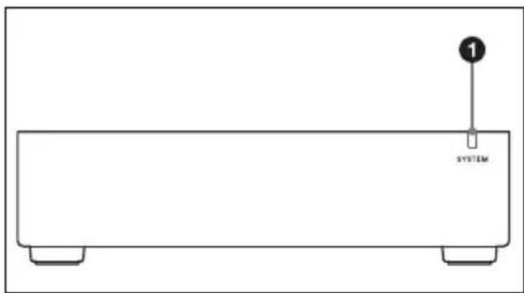
前面
natural_image
Simple line drawing of a rectangular electronic device with a labeled component (no text or symbols beyond the label)① SYSTEM インジケーター
本機の状態を示します。
Before operating the unit, please read this manual thoroughly and retain it for future reference.
WARNING
To reduce the risk of fire or electric shock, do not expose this apparatus to rain or moisture.
To avoid electrical shock, do not open the cabinet. Refer servicing to qualified personnel only.
This unit has no power switch.
When installing the unit, incorporate a readily accessible disconnect device in the fixed wiring, or connect the power plug to an easily accessible socket-outlet near the unit. If a fault should occur during operation of the unit, operate the disconnect device to switch the power supply off, or disconnect the power plug.
When installing the installation space must be secured in consideration of the ventilation and service operation.
- Do not block the ventilation slots at the left side and right side panels, and vents of the fans.
- Leave a space around the unit for ventilation.
- Leave more than 40~cm of space in the rear of the unit to secure the operation area.
When the unit is installed on the desk or the like, leave at least 4 cm of space in the left and right sides. Leaving 40 cm or more of space above the unit is recommended for service operation.
WARNING: THIS WARNING IS APPLICABLE FOR USA ONLY.
If used in USA, use the UL LISTED power cord specified below.
DO NOT USE ANY OTHER POWER CORD.
Plug Cap Parallel blade (NEMA 1-15P Configuration)
Cord Type NISPT-2 or SPT-2, two 16 or 18 AWG wires
Length Minimum 1.5 m (4 ft 11 in), Less than 2.5 m (8 ft 3 in)
Rating Minimum 7A, 125V
Using this unit at a voltage other than 120V may require the use of a different line cord or attachment plug, or both. To reduce the risk of fire or electric shock, refer servicing to qualified service personnel.
WARNING: THIS WARNING IS APPLICABLE FOR OTHER COUNTRIES.
-
Use the approved Power Cord (2-core mains lead) / Appliance Connector / Plug that conforms to the safety regulations of each country if applicable.
-
Use the Power Cord (2-core mains lead) / Appliance Connector / Plug conforming to the proper ratings (Voltage, Ampere).
If you have questions on the use of the above Power Cord / Appliance Connector / Plug, please consult a qualified service personnel.
IMPORTANT
The nameplate is located on the bottom.
For the customers in the U.S.A.
This equipment has been tested and found to comply with the limits for a Class A digital device, pursuant to part 15 of the FCC Rules. These limits are designed to provide reasonable protection against harmful interference when the equipment is operated in a commercial environment. This equipment generates, uses and can radiate radio frequency energy and, if not installed and used in accordance with the instruction manual, may cause harmful
interference to radio communications. Operation of this equipment in a residential area is likely to cause harmful interference in which case the user will be required to correct the interference at his own expense.
You are cautioned that any changes or modifications not expressly approved in this manual could void your authority to operate this equipment.
All interface cables used to connect peripherals must be shielded in order to comply with the limits for a digital device pursuant to Subpart B of part 15 of FCC Rules.
This device complies with part 15 of the FCC Rules. Operation is subject to the following two conditions: (1) This device may not cause harmful interference, and (2) this device must accept any interference received, including interference that may cause undesired operation.
For the customers in Canada CAN ICES-3 (A)/NMB-3(A)
For the customers in Europe
This product is intended for use in the following Electromagnetic Environments: E2 (commercial and light industrial), E3 (urban outdoors), E4 (controlled EMC environment, ex. TV studio).
For the customers in Europe, Australia and New Zealand
WARNING
This equipment is compliant with Class A of CISPR 32. In a residential environment this equipment may cause radio interference.
For the customers in Europe
This apparatus shall not be used in the residential area.
For the customers in the U.S.A.
SONY LIMITED WARRANTY -
Please visit http://www.sony.com/psa/warranty for important information and complete terms and conditions of Sony's limited warranty applicable to this product.
For the customers in Canada SONY LIMITED WARRANTY -
Please visit http://www.sonybiz.ca/pro/lang/en/ca/article/resources-warranty for important information and complete terms and conditions of Sony's limited warranty applicable to this product.
For the customers in Europe
Sony Professional Solutions Europe - Standard Warranty and Exceptions on Standard Warranty.
Please visit http://www.pro.sony.eu/warranty for important information and complete terms and conditions.
For the customers in Korea SONY LIMITED WARRANTY -
Please visit http://bpeng.sony.co.kr/ handler/BPAS-Start for important information and complete terms and conditions of Sony's limited warranty applicable to this product.
Usage Precautions
Condensation
If the unit is suddenly taken from a cold to a warm location, or if ambient temperature suddenly rises, moisture may form on the outer surface of the unit and/or inside of the unit. This is known as condensation. If condensation occurs, turn off the unit and wait until the condensation clears before operating the unit. Operating the unit while condensation is present may damage the unit.
Consumable parts
The fan is a consumable part that will need periodic replacement.
When operating at room temperature, a normal replacement cycle will be about 5 years.
However, this replacement cycle represents only a general guideline and does not imply that the life expectancy of this part is guaranteed. For details on parts replacement, contact your dealer.
The life expectancy of the AC adapter and the electrolytic capacitor is about 5 years under normal operating temperatures and normal usage (8 hours per day; 25 days per month). If usage exceeds the above normal usage frequency, the life expectancy may be reduced correspondingly.
The battery terminal of this unit (the connector for battery packs and AC adaptors) is a consumable part.
Power may not be supplied to the unit properly if the pins of the battery terminal are bent or deformed by shock or vibrations, or if they become corroded due to prolonged outdoor use.
Periodic inspections are recommended to keep the unit working properly and to prolong its usable lifetime.
Contact a Sony service or sales representative for more information about inspections.
Precautions for Network-enabled Devices
SONY WILL NOT BE LIABLE FOR DAMAGES OF ANY KIND RESULTING FROM A FAILURE TO IMPLEMENT PROPER SECURITY MEASURES ON TRANSMISSION DEVICES, UNAVOIDABLE DATA LEAKS RESULTING FROM TRANSMISSION SPECIFICATIONS, OR SECURITY PROBLEMS OF ANY KIND.
From a safety standpoint, when using the unit connected with the network, it is strongly recommended to access the Control window via a Web browser and change the access limitation settings from the factory preset values (refer to Installation Manual).
Changing the password regularly is also recommended.
Do not browse any other website in the Web browser while making settings or after making settings. Since the login status remains in the Web browser, close the Web browser when you complete the settings to prevent unauthorized third parties from using the unit or harmful programs from running.
Depending on the operating environment, unauthorized third parties on the network may be able to access the unit. When connecting the unit to the network, be sure
to confirm that the network is protected securely.
Notes on video output
Images and audio may be distorted for approximately 90 seconds after the unit is turned on.
Features
The NXL-IP4F SDI-IP Converter Unit is a monitor adapter that allows you to output and display IP video streams on conventional SDI-compatible broadcast monitors.
Supported Formats
3840x2160 Level-A 2SI 59.94p/50p LLVC compressed 3G Quad Link 1980x1080 59.94i/50i uncompressed 1.5G
Parts Identification
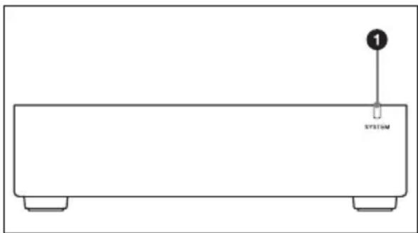
Front
natural_image
Simple line drawing of a rectangular electronic device with two base legs and a labeled component (no text or symbols beyond the label)① SYSTEM indicator
Indicates the status of the unit. For details, see “SYSTEM Indicator” (page 11).

Warning
If the SYSTEM indicator is rapidly blinking orange, do not touch the unit. The unit may be hot due to a cooling malfunction caused by a fan error or blocked ventilation holes, and touching the connectors may result in burns. Disconnect the DC connector, and wait for the unit to cool down sufficiently before touching it.
Rear
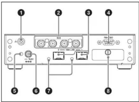
① Equipotential grounding terminal
②SDI video (output) connectors 1 to 4
③NMI LAN connectors 1 and 2*
* The connector on the right (when facing the rear of the unit) is NMI LAN connector 1.
④RS-232C connector (cannot be used)
⑤DC plug clamp attachment point
⑥DC IN connector
⑦LINK indicators 1 and 2
For details, see "LINK Indicator" (page 11).
⑧DIP switches 1 to 3 (cannot be used)
Indicators
SYSTEM Indicator
Indicates the status of the unit.
| System status Ind | cator |
| No DC power supply | Off |
| Startup in progress (including during video and network synchronization) | Blinking (green) |
| Startup complete (no video transmission) | Slow blinking (green, 2-sec. interval) |
| Video transfer in progress | Lit (green) |
| Fan error Rapid blinking | (orange, 0.5-sec. interval) |
| Internal temperature error | Blinking (orange, 1-sec. interval) |
| Low optical module power supply | Blinks 2 times (orange) |
| Network error Blinks | 3 times (orange) |
| Other error Blinks 4 times | (orange) |
If the indicator does not light (green) after turning the power on, contact a technician or your local Sony representative.
LINK Indicator
Indicates the network connection status.
| Network status Indicator | |
| Normal status Lit (green) | |
| Awaiting connection Blinking (green) | |
| Connection not required | Off |
If the “awaiting connection” status continues, check the network connection.
Installation
To use this unit, settings must be configured according to the installation manual. For details on acquiring the installation manual, contact your local Sony service representative.
A DHCP server is required to configure the unit.
Errors
The SYSTEM indicator notifies you of various errors that can occur on the unit. Refer to the following section to resolve the errors. Always check whether an error notification also appears on IP Live System Manager.
| SYSTEM indicator Description Solution | ||
| Rapid blinking (orange, 0.5-sec. interval) | Fan error A fan error has occurred. | |
| Blinks 3 times (orange) | Network error | A network error has occurred. Check the network connection. |
| Blinking (green) | Network synchronization in progress | Network synchronization is in progress. If the problem does not resolve itself after a moment, contact your local Sony representative. |
| Blinks 4 times (orange) | Other error | A system error has occurred. Contact your local Sony representative. |
| Blinking (orange, 1-sec. interval) | Internal temperature error | An internal temperature error has occurred. Check the operating environment. |
| Blinks 2 times (orange) | Low optical module power supply | The power supplied to the optical modules installed at NMI LAN connectors 1 and 2 is low.Clean the optical connectors and the contacts on the optical fiber cable, or replace the optical modules. For details on cleaning or replacing optical modules, contact your local Sony representative. |
Specifications
General
Power supply
19.5 V DC
Current consumption
1.2 A
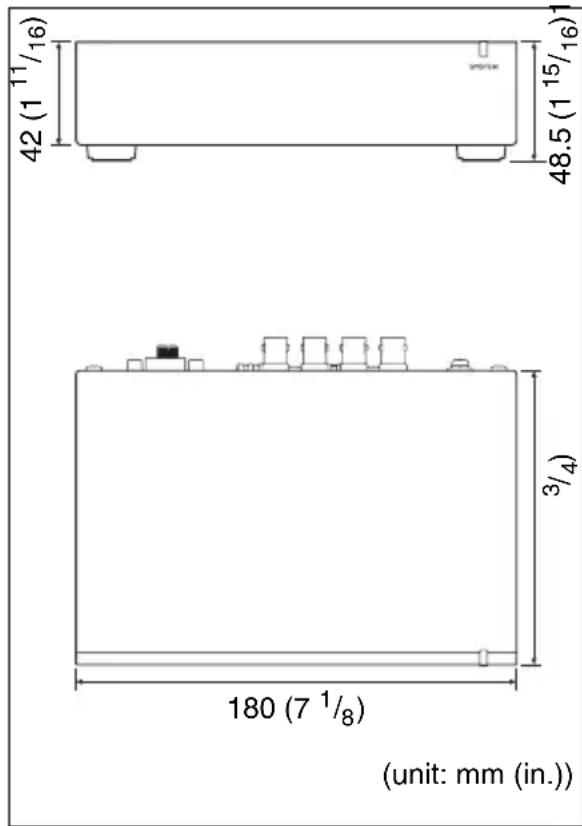
Dimensions
$$ 1 8 0 \times 4 2 \times 1 2 0 \mathrm{mm} $$
$$ (7 ^ {1} / _ {8} \times 1 ^ {1 1} / _ {1 6} \times 4 ^ {3} / _ {4} \text {in.}) $$
$$ (\mathrm{W} \times \mathrm{H} \times \mathrm{D}; \text {excluding} $$
connectors and feet)
Mass Approx. 650 g (1 lb. 6.9 oz.)
Temperature range
Operation guaranteed
$$ 5 ^ {\circ} \mathrm{C} \text {to} 4 0 ^ {\circ} \mathrm{C} (4 1 ^ {\circ} \mathrm{F} \text {to} 1 0 4 ^ {\circ} \mathrm{F}) $$
Performance guaranteed
$$ 1 0 ^ {\circ} \mathrm{C} \text { to } 3 5 ^ {\circ} \mathrm{C} (5 0 ^ {\circ} \mathrm{F} \text { to } 9 5 ^ {\circ} \mathrm{F}) $$
Storage
$$ - 2 0 ^ {\circ} \mathrm{Cto} + 6 0 ^ {\circ} \mathrm{C} (- 4 ^ {\circ} \mathrm{Fto} $$
$$ + 1 4 0 ^ {\circ} \mathrm{F}) $$
I/O interfaces
SDI Connector
$$ 7 5 \Omega \text { BNC type } $$
Lines
$$ 4 $$
Signal format
$$ \text { SMPTE ST 424, SMPTE ST } $$
$$ 2 9 2 - 1 $$
$$ \text { Only 2 ch (48 kHz 24 bit) } $$
$$ \text { embedded audio supported } $$
NMI LAN
Connector
$$ \mathrm{SFP+} $$
Lines
$$ 2 $$
Signal format
$$ 1 0 \text { GBASE- } ^ { } (\text { depending on } $$
$$ \text { SFP+ transceiver module) } $$
$$ \text { For details on supported SFP+ } $$
$$ \text { transceiver modules, contact } $$
$$ \text { your local Sony representative. } $$
DC IN 19.5 V
RS-232C (cannot be used)
Connector
$$ 9 - \text { pin D - Sub } $$
Lines
$$ 1 $$
Supplied accessories
Operation Manual (1)
AC adapter (1)
Clamp (1)
Optional accessories
Power cord
The service part number is as follows.
Japan: 1-846-423-6x
North America: 1-846-425-5x
Europe: 1-846-428-7x
China: 1-846-433-7x
Design and specifications are subject to change without notice.
This product uses GPL. For details on the licenses and how to reference them, refer to the installation manual.
Notes
• Always verify that the unit is operating properly before use. SONY WILL NOT BE LIABLE FOR DAMAGES OF ANY KIND INCLUDING, BUT NOT LIMITED TO, COMPENSATION OR REIMBURSEMENT ON ACCOUNT OF THE LOSS OF PRESENT OR PROSPECTIVE PROFITS DUE TO FAILURE OF THIS UNIT, EITHER DURING THE WARRANTY PERIOD OR AFTER EXPIRATION OF THE WARRANTY, OR FOR ANY OTHER REASON WHATSOEVER.
- SONY WILL NOT BE LIABLE FOR CLAIMS OF ANY KIND MADE BY USERS OF THIS UNIT OR MADE BY THIRD PARTIES.
- SONY WILL NOT BE LIABLE FOR THE TERMINATION OR DISCONTINUATION OF ANY SERVICES RELATED TO THIS UNIT THAT MAY RESULT DUE TO CIRCUMSTANCES OF ANY KIND.
Français
natural_image
Simple line drawing of a rectangular electronic device with two base legs and a labeled component (no text or symbols beyond the label)①Indicateur SYSTEM
natural_image
Simple line drawing of a rectangular electronic device with two base legs and a labeled component (no text or symbols beyond the label)①Anzeige SYSTEM
Audio (48 kHz, 24 Bit)
unterstützt
Netzwerk
Anschluss
SFP+
Leitungen
2
Signalformat
Installationshandbuch.
Hinweise
natural_image
Simple line drawing of a rectangular electronic device with two base legs and a labeled component (no text or symbols beyond the label)①Indicatore SYSTEM
Quad Link 3G comprimido LLVC 59.94p/
50p 2SI Level-A 3840x2160
1.5G descomprimido 59.94i/50i 1980x1080
natural_image
Simple line drawing of a rectangular electronic device with two base legs and a labeled component (no text or symbols beyond the label)①Indicador SYSTEM
natural_image
Simple line drawing of a rectangular electronic device with two base legs and a labeled component (no text or symbols beyond the label)① SYSTEM 指示灯
指示设备状态。


