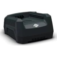
82C1G - Battery charger Cramer - Free user manual and instructions
Find the device manual for free 82C1G Cramer in PDF.


| Product type | Lithium-ion battery charger |
| Brand | Cramer |
| Model | 82C1G |
| Input voltage | 230 V ~ 50/60 Hz, 2.5 A |
| Output voltage | 82 V = 4 A |
| Compatible batteries | 82V220G (72 V / 3 Ah / 216 Wh) and 82V430G (72 V / 6 Ah / 432 Wh) |
| Charging time | 45 min (82V220G), 90 min (82V430G) |
| LED indicators | Flashing green (charging), Solid green (charged), Solid red (excessive temperature), Flashing red (fault) |
| Protection | Overheating, short-circuit, overload |
| Usage | Indoor only |
| Protection class | Class II |
| Wall mounting | Yes, mounting centre distance 114.3 mm |
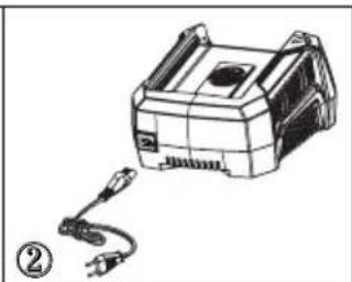
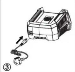
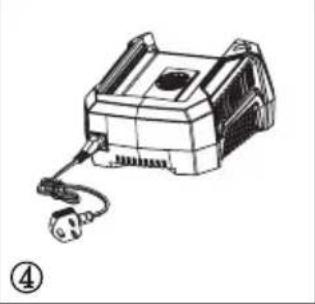
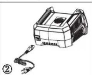
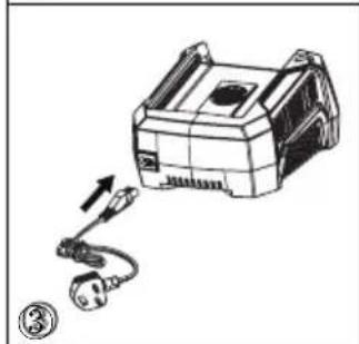
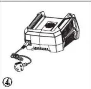
| Power cord | Detachable and interchangeable |
| Dimensions (approx.) | 200 x 150 x 100 mm |
| Weight (approx.) | 1 kg |
| Material | Plastic |
| Cleaning | Dry soft cloth |
Frequently Asked Questions - 82C1G Cramer
User questions about 82C1G Cramer
0 question about this device. Answer the ones you know or ask your own.
Ask a new question about this device
Download the instructions for your Battery charger in PDF format for free! Find your manual 82C1G - Cramer and take your electronic device back in hand. On this page are published all the documents necessary for the use of your device. 82C1G by Cramer.
USER MANUAL 82C1G Cramer
82V220G/ 82V430G/ 82C1G (2905786/ 2905886/ 2905686)
EN | DE | ES | IT | FR | PT | NL | RU | FI | SV | NO | DA |
PL | CS | SK | SL | HR | HU | RO | BG | EL | AR | TR | HE |
LT | LV | ET |
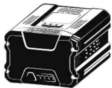
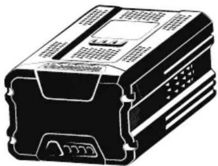
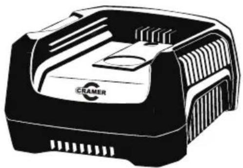
English (Original Instructions)
BATTERY
SPECIFICATIONS
82V220G
Battery: 72V =3Ah, 216Wh, 82V MAX
Voltage per cell: 3.6V ; Number of cells: 20
Charge time: 45 min. (use 82C1G Charger)
82V430G
Battery: 72V =6Ah, 432Wh, 82V MAX
Voltage per cell: 3.6V ; Number of cells: 40
Charge time: 90 min. (use 82C1G Charger)
For the proper use, maintenance and storage of this battery, it is crucially important that you read and understand the instructions given in this manual.
To avoid serious injury, risk of fire, explosion and danger of electric shock or electrocution:
■ If the battery pack case is cracked or damaged, DO NOT insert into the charger. Replace with a new battery pack.
■ DO NOT charge these battery packs with any other type of charger.
■ DO NOT try to short circuit any terminals of battery pack.
WARNING
If the battery fluid gets in your eyes, rinse immediately with clean water for at least 15 minutes. Get immediate medical attention. Do not charge the battery pack in rain or in wet conditions. Do not immerse the tool, battery pack, or charger in water or other liquid.
■ Do not allow the battery pack or charger to overheat. If they are warm, allow them to cool down. Recharge only at room temperature.
■ Do not place the battery pack in the sun or in a warm environment. Keep at normal room temperature.
- Keep in shady, cool and dry condition, if the battery is not charged for a long time; charge the battery for 2 hours every 2 months.
■ The battery pack cells may develop a small
leak under extreme usage or temperature conditions. If the outer seal is broken and the leakage gets on your skin:
- Use soap and water to wash immediately.
- Neutralize with lemon juice, vinegar, or other mild acid.
■ If leakage gets in your eyes, follow instructions above and seek medical attention.
■ Please check prior use, if output voltage and current of the battery charger is suitable for the charging battery pack.
CHECKING BATTERY CAPACITY
Press the battery capacity indicator (BCI) button. The lights will illuminate according to the batteries capacity level. See chart below:
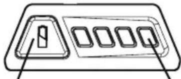
BATTERY CAPACITY
INDICATOR (BCI) BUTTON
LIGHT METER
| Lights | Capacity |
| 4 Green Lights he | Battery is above 80% capacity |
| 3 Green Lights he | Battery is between 80% and 60% capacity |
| 2 Green Lights he | Battery is between 60% and 40% capacity |
| 1 Green Light The | battery is between 40% and 25% capacity |
| Lights go out | The battery is less than 25% capacity and requires charging immediately |
SAFETY NOTES AND PRECAUTIONS
-
Do not disassemble the battery.
-
Keep away from the children.
-
Do not expose the battery to water or salt water, battery should be stored in a cool and dry location and should place the battery in cool and dry environment.
-
Do not place the battery in high-temperature locations, such as near a fire, heater, etc.
-
Do not reverse the positive terminal and the negative terminal of the battery.
-
Do not connect the positive terminal and the negative terminal of the battery to each other with any metal objects.
-
Do not knock, strike or step on the battery.
English (Original Instructions)
- Do not solder directly onto the battery and pierce the battery with nails or other edge tools.
- In the event that the battery leaks and the fluid gets into one's eye, do not rub the eye. Rinse well with water. Immediately discontinue use of the battery, if, while using the battery emits an unusual smell, feels hot, changes color, changes shape, or appears abnormal in any other way.
BATTERY CHARGER
SPECIFICATIONS
82V Charger: 82C1G
Input: 230V \~50/60Hz, 2.5A
Output: 82V =4A
■ DO NOT probe the charger with conductive materials.
■ DO NOT allow liquid inside the charger.
■ DO NOT try to use the charger for any other purpose than what is presented in this manual.
■ Unplug the charger before cleaning and when there is no battery pack in the charger.
■ Do not try to connect two chargers together.
■ Do not use the charger in the circumstances that the output Polarity does not match the load polarity.
■ For indoor use only.
■ The cover may under no circumstances be opened. If the cover is damaged, then the charger may no longer be used.
■ Do not recharge non-rechargeable batteries.
WARNING
To avoid risk of fire, electric shock, or electrocution:
- Do not use a damp cloth or detergent on the battery or battery charger.
- Always remove the battery pack before cleaning, inspecting, or performing any maintenance on the tool.
CLEANING
Wipe the outside of the charger with a dry, soft cloth. Do not hose down or wash with water.
 | Class II |
 | For indoor use only |
 | Before charging, read the instructions |
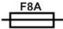 | Fuse |
WARNING
This appliance can be used by children aged from 8 years and above and persons with reduced physical, sensory or mental capabilities or lack of experience and knowledge if they have been given supervision or instruction concerning use of the appliance in a safe way and understand the hazards involved.
- Children shall not play with the appliance.
- Cleaning and user maintenance should not be made by children without supervision.
- If the supply cord is damaged, it must be replaced by manufacturer, its service agent or similarly qualified persons in order to aviod a hazard.
- Do not cover the ventilation slots on the top of the charger. Do not set the charger on a soft surface i.e. blanket, pillow. Keep the ventilation slots of the charger clear.
- Do not allow small metal items or material such as steel wool, aluminum foil, or other foreign particles into the charger cavity.
- Use only 82V220G/82V430G rechargeable Li-ion batteries.
English (Original Instructions)
ENVIRONMENTALLY SAFE BATTERY DISPOSAL

WARNING
If the battery pack cracks or breaks, with or without leaks, do not recharge it and do not use. Dispose of it and replace with a new battery pack. DO NOT ATTEMPT TO REPAIR IT!
To avoid injury and risk of fire, explosion, or electric shock, and to avoid damage to the environment:
- Cover the battery's terminals with heavy-duty adhesive tape.
- DO NOT attempt to remove or destroy any of the battery pack components.
- DO NOT attempt to open the battery pack.
WARNING
- If a leak develops, the released electrolytes are corrosive and toxic. DO NOT get the solution in the eyes or on skin, and do not swallow it.
- DO NOT place these batteries in your regular household trash.
- DO NOT incinerate.
- DO NOT place them where they will become part of any waste landfill or municipal solid waste stream.
- Take them to a certified recycling or disposal centre.
CHARGING PROCEDURE
NOTE: The battery is not shipped fully charged. It is recommended to fully charge before use to ensure that maximum run time can be achieved. This lithium-ion battery will not develop a memory and may be charged at any time.
- Plug the charger into an AC power outlet.
- Insert the battery pack (1) into the charger (2).
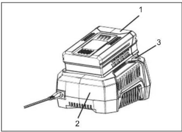
This is a diagnostic charger. The Charger LED Light (3) will illuminate in specific order to communicate the current battery status. They are as follows:
| LED STATUS DESCRIPTION | |
| Blinking Green Charging | |
| Solid Green Fully Charged | |
| Solid Red Over Temperature | |
| Blinking Red Charging Fault | |
False Defect Note:
When the battery is inserted into the charger, and the status LED flashes, remove the battery from the charger for 1 minute, then reinsert. If the status LED indicates normal than the battery pack is good. If the status LED is still blinking, remove the battery pack and unplug the charger. Wait 1 minute and plug the charger back in and reinsert the battery pack. If the status LED indicates normal than the battery pack is good. If the status LED is still blinking then the battery pack is defective and needs to be replaced.
NOTE: When the red indicator flickers, pull out the battery from the charger and insert again within 2 hours. If the indicator shows charging, that means the battery is good. After 2 hours, please pull out the battery and also pull out the AC power plug of the charger for 1 minute, and then insert the AC power plug and the battery again. If the indicator shows charging, that means the battery is good. If not, the battery needs to be changed.
English (Original Instructions)
CHECKING THE CHARGER
If the battery pack does not charge properly:
- Check the current at the power outlet with another tool. Make sure that the outlet is not turned off.
- Check that the charger contacts have not been shorted by debris or foreign material.
- If the surrounding air temperature is not normal room temperature, move the charger and battery pack to a location where the temperature is between 7 °C and 40°C.
WARNING
If the battery is inserted into the charger when warm or hot, the CHARGING LED indicator light on the charger may switch on and illuminate RED. If this occurs allow the battery to cool outside of the charger for approximately 30 minutes.
CHARGER MOUNTING
- This charger can be installed hanging on a wall using two screws (not supplied).
- Locate the placement for the charger to be wall mounted.
- If fastening to wood studs use 2 wood screws.
- Drill two holes on center 114.3mm apart ensuring that they are vertically aligned.
- If fastening to drywall use wall anchors and screws to secure the charger to the wall.
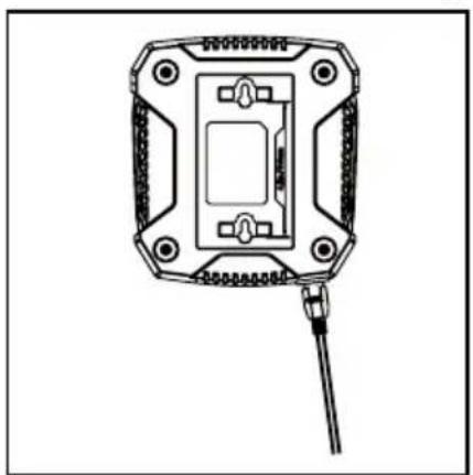
NOTE: If the battery and the charger won't be used for a long time, please remove the battery from the charger and pull out the AC power plug.
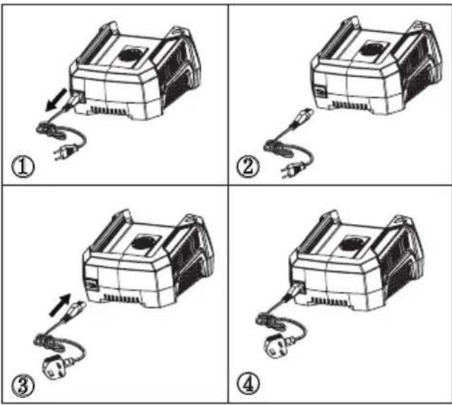
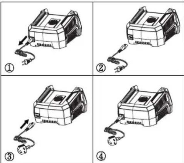
DETACHABLE POWER CORD
The power cords of the charger are detachable. They can be removed from the charger and used interchangeably. (See the figure below)
IMPORTANT SAFETY INSTRUCTIONS
- SAVE THESE INSTRUCTIONS - DANGER: TO REDUCE RISK OF FIRE OR ELECTRIC SHOCK CAREFULLY FOLLOW THESE INSTRUCTIONS.
- Confirm the voltage available at each country location before using the charger.
- If the shape of the plug does not fit the power outlet, use an attachment plug adaptor of the proper configuration for the power outlet.
CORRECT DISPOSAL OF THIS PRODUCT:
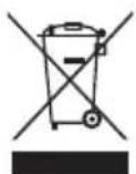
This marking indicates that this product should not be disposed with other household wastes throughout the EU. To prevent possible harm to the environment or human health from uncontrolled waste disposal, recycle it responsibly to promote the sustainable reuse of material resources. To return your used device, please use the return and collection systems or contact the retailer where the
English (Original Instructions)
product was purchased. They can take this product for environmental safe recycling.
REMOVAL OF WASTE BATTERIES AND ACCUMULATORS
Li-ion
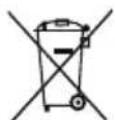
Member States shall ensure that manufacturers design appliances in such a way that waste batteries and accumulators can be readily removed. Where they cannot be readily removed by the end-user. Member States shall ensure that manufacturers design appliances in such a way that waste batteries and accumulators can be readily removed by qualified professionals that are independent of the manufacturer. Appliances in which batteries and accumulators are incorporated shall be accompanied by instructions on how those batteries and accumulators can be safely removed by either the end-user or by independent qualified professionals. Where appropriate, the instructions shall also inform the end-user of the types of battery or accumulator incorporated into the appliance.
TASTO INDICATORE CAPACITA' BATTERIA MISURAZIONE (BATTERY CAPACITY INDICATOR - BCI) CARICA BATTERIA
CHARGE DE LA BATTERIE VOYANT LUMINEUX BOUTON INDICATEUR (BCI)
CORDON D'ALIMENTATION AMOVIBLE
MISE AU REBUT CORRECTE DE CE PRODUIT :
BATTERIJVERMOGENSINDICATIE ACCUMETER (BVI) KNOP
CORRECTE AFVOER VAN DIT PRODUCT:
AKUN VARAUKSEN AKKUMITTARI MERKKIVALO (BCI) -PAINIKE
| Valot | Kapasiteetti |
| 4 vihreää valoa | Batteriet er ca. 80% over kapasitet. |
| 3 vihreää valoa | Batteriet er mellom 80% og 60% av kapasitet. |
| 2 vihreää valoa | Batteriet er mellom 60% og 40% av kapasitet. |
| 1 vihreä valoB atteriet er mellom 40% og 25% av kapasitet. | |
| Valot sammuvat | Akun kapasiteetti on alle 25 %, ja se on ladattava heti. |
TURVALLISUUSILMOITUKSET JA VAROTOIMET
BATTERIKAPACITETSINDIKATORKNAPP BATTERIMÄTARE BATTERIMÄTARE (BCI).
Akumulator: 72V = 3Ah, 216Wh, 82V maks.
Akumulator: 72V = 6Ah, 432Wh, 80V maks.
KNAPP FOR MIERNIK BATTERIKAPASITETINDIKATOR (BCI) AKUMULATORA
KORREKT AVHENDING AV DETTE PRODUKTET:
BATTERIKAPACITETS-INDIKATOR BATTERIMÄLER (BCI) KNAP
PRZYCISK WSKAŻNIKA STANU
MIERNIK
NAŁADOWANIA AKUMULATORA (BCI) AKUMULATORA
TLAČÍTKO INDIKACE KAPACITY MÍRA BATERIE BATERIE (BCI)
TLAČIDLO INDIKÁTORA NABITIA AKUMULÁTORA (ICB)
DÔLEŽITÉ BEZPEČNOSTNÉ POKYNY
- UCHOVAJTE SI TIETO POKYNY NEBEZPEČIE: PRE ZNÍŽENIE RIZIKA POŽIARU ALEBO ELEKTRICKÝCH VÝBOJOV JE POTREBNÉ DODRŽIAVAŤ NASLEDUJÚCE POKYNYI.
- Pred použitím dobíjačky preverte aké napätie je dostupné v danej krajine.
3.Ak tvar zástrčky nesedí do elektrickej
Akumulator: 72V =3Ah, 216Wh, 82V MAX
Akumulator: 72V =6Ah, 432Wh, 82V MAX
GUMB INDIKATORJA
NAPOLNJENOSTI
MERILNIK LUČK
AKUMULATORJA (BCI).
| Lučke | Napolnjenost |
| 4 zelene lučke | Akumulator je nad 80 % napolnjenosti |
| 3 zelene lučke | Akumulator je med 80 % in 60 % napolnjenosti |
| 2 zeleni lučki | Akumulator je med 60 % in 40 % napolnjenosti |
| 1 zelena lučka | Akumulator je med 40 % in 25 % napolnjenosti |
| Lučke ugasnejo | Akumulator je pod 25 % napolnjenosti in ga je treba takoj napolniti. |
OPOMBE IN UKREPI ZA VARNOST
TIPKA INDIKATOR
NAPUNJENOSTI BATERIJE (INB)
MJERENJE
| Svjetla | Stanje napunjenosti |
| 4 zelena svjetla | Napunjenost baterije je veća od 80% |
| 3 zelena svjetla | Napunjenost baterije je između 80% i 60% |
| 2 zelena svjetla | Napunjenost baterije je između 60% i 40% |
| 1 zeleno svjetlo | Napunjenost baterije je između 40% i 25% |
| Svjetla se gase | Napunjenost baterije je manja od 25%Bateriju treba odmah napuniti. |
SIGURNOSNE NAPOMENE I MJERE OPREZA
-
NE rastavljajte bateriju.
-
Držite izvan dohvata djece.
-
Bateriju NE izlažite slanoj ili slatkoj vodi, pohranite je na hladnom i suhom mjestu.
-
Bateriju NE stavljajte blizu suviše toplih
NAPOMENA: Ako punjač i bateriju ne
koristite duže vrijeme, izvadite bateriju iz punjača i punjač iskopčajte iz strujne utičnice.
ODSPOJIVI KABEL ZA NAPAJANJE
Kabeli za napajanje punjača se mogu odspojiti. Mogu se ukloniti s punjača i koristiti samostalno. (pogledajte sliku u nastavku)
VAŽNI SIGURNOSNI UPUTI
- SAČUVAJTE OVE UPUTE OPASNOST: KAKO BI SE SMANJIO RIZIK OD POŽARA ILI STRUJNOG UDARA, VAŽNO JE PAŽLJIVO SLIJEDITI OVE UPUTE.
- Prije uporabe punjača provjerite napon dostupan u svakoj zemlji korištenja.
- Ako oblik utikača ne odgovara utičnici za napajanje, koristite prkiljučak adaptera za utičnicu za pravilnu konfiguraciju utičnice za napajanje.
PRAVILNO ZBRINJAVANJE PROIZVODA:
Ova oznaka naznačuje da se ovaj proizvod ne smije odlagati s ostalim kućanskim otpadom u cijeloj EU. Kako biste spriječili moguće štete za prirodno okruženje ili ljudsko
AKKUMULÁTORTÖLTÖM
JELZÖ GOMB (ICB)
ÉRES
Accumulator: 72V =3Ah, 216Wh, 82V MAX
TASTĂ PENTRU ÎNCĂRCĂTOR (ICB)
INSTRUCTIUNI SIGURANTĂ
IMPORTANTEDE
زر مؤشر سعة
(BCI) البطارية
مقياس
الضوء
PİL ŞARJ GÖSTERGEGİ
(PŞG) TUŞU
LÇÜM
בַרְשָׁה בַרְשָׁה
תַלְרָה בְּרָה
(BCI)
.הכלההוּרָהוּרָהוּרָהוּרָהוּרָהוּרָהוּרָהוּרָהוּרָהוּרָהוּרָהוּרָהוּרָהוּרָהוּרָה
תְבָרִיָה (3) אַעֹשֵׁוּוֹם. וְאַעֹשֵׁוֹם לַעֹשֵׁוֹם. וְאַעֹשֵׁוֹם לַעֹשֵׁוֹם לַעֹשֵׁוֹם:
AKUMULIATORIAUS M
KROVIKLIO INDIKATORIUS (ICB)
ATAVIMAS
| Lemputés | Talpa |
| 4 žalios lemputés | Akumuliatorius jkrautas daugiau nei 80%. |
| 3 žalios lemputés | Akumuliatorius jkrautas nuo 80% iki 60% |
| 2 žalios lemputés | Akumuliatorius jkrautas nuo 60% iki 40% |
| 1 žalia lemputé | Akumuliatorius jkrautas nuo 40% iki 25% |
| Lemputés užgęsta | Akumuliatorius jkrautas mažiau nei 25% Akumuliatorius turi būti nedelsiant jkrautas. |
SAUGUMO IR ATSARGUMO REKOMENDACIJOS
AKUMULATORA UZLÃDES
LÎMENA INDIKATORA (ICB)
TAUSTINŠ
MÉRÍJUMS
AKULAETUVUSE
KONTROLLNUPP (ICB)
MÕÕTMINE
EC DECLARATION OF CONFORMITY
Manufacturer: Changzhou Globe Co., Ltd.
Address: No.65 Xinggang Road Zhonglou Zone Changzhou, Jiangsu 213000 P.R.China
Name and address of the person authorised to compile the technical file:
Name: Peter Söderström
Address: Propellergatan 1, 211 15 Malmö, Sweden
Herewith we declare that the product
Category: 82V battery charger
Model: 2905686
Serial number: See product rating label
Year of Construction: See product rating label
■ is in conformity with the relevant provisions of the Low Voltage Directive 2014/35/EU
■ is in conformity with the provisions of the following other EMC directive (2014/30/EU).
And furthermore, we declare that
the following (parts/clauses of) European harmonised standards have been used
EN 60335-2-29, EN 60335-1, EN 62233, EN 55014-1,
EN 55014-2, EN 61000-3-2, EN 61000-3-3
Place, date: Changzhou, 19/08/2017
Signature: Ted Qu Haichao
Quality Director

DÉCLARATION DE CONFORMITÉ CE
Fabricant: Changzhou Globe Co., Ltd.
Adresse : No.65 Xinggang Road Zhonglou Zone Changzhou, Jiangsu 213000 R. P. de Chine
Endereço: No.65 Xinggang Road Zhonglou Zone Changzhou, Jiangsu 213000 China
DEKLARACJA ZGODNOŚCI WE
Producent: Changzhou Globe Co., Ltd.
Adres: Nr 65 Xinggang Road Zhonglou Zone Changzhou, Jiangsu 213000, ChRL
Adresa: No.65 Xinggang Road Zhonglou Zone Changzhou, Jiangsu 213000, Republica Populară Chineză
No.65 Xinggang Road Zhonglou Zone Changzhou, Jiangsu:
213000 P.R.China.
Yer, tarih: Changzhou, 19/08/2017
Imza: Ted Qu Haichao
Kalite Müdürü
No.65 Xinggang Road Zhonglou Zone Changzhou, Jiangsu:
213000 P.R.China
Changzhou, 19/08/2017:
Ted Qu
Ted Qu

EB ATITIKTIES DEKLARACIJA
Gamintojas: Changzhou Globe Co., Ltd.
Adresas: No.65 Xinggang Road Zhonglou Zone Changzhou, Jiangsu 213000, Kinija
Adrese: No.65 Xinggang Road Zhonglou Zone Changzhou, Jiangsu 213000 P.R.China



- 82V220G/ 82V430G/ 82C1G (2905786/ 2905886/ 2905686)
- ENGLISH (ORIGINAL INSTRUCTIONS)
- BATTERY
- SPECIFICATIONS
- WARNING
- CHECKING BATTERY CAPACITY
- SAFETY NOTES AND PRECAUTIONS
- BATTERY CHARGER
- CLEANING
- ENVIRONMENTALLY SAFE BATTERY DISPOSAL
- CHARGING PROCEDURE
- FALSE DEFECT NOTE
- CHECKING THE CHARGER
- CHARGER MOUNTING
- DETACHABLE POWER CORD
- IMPORTANT SAFETY INSTRUCTIONS
- CORRECT DISPOSAL OF THIS PRODUCT
- REMOVAL OF WASTE BATTERIES AND ACCUMULATORS
- CORDON D'ALIMENTATION AMOVIBLE
- MISE AU REBUT CORRECTE DE CE PRODUIT
- CORRECTE AFVOER VAN DIT PRODUCT
- TURVALLISUUSILMOITUKSET JA VAROTOIMET
- KORREKT AVHENDING AV DETTE PRODUKTET
- DÔLEŽITÉ BEZPEČNOSTNÉ POKYNY
- OPOMBE IN UKREPI ZA VARNOST
- SIGURNOSNE NAPOMENE I MJERE OPREZA
- ODSPOJIVI KABEL ZA NAPAJANJE
- VAŽNI SIGURNOSNI UPUTI
- PRAVILNO ZBRINJAVANJE PROIZVODA
- INSTRUCTIUNI SIGURANTĂ
- IMPORTANTEDE
- SAUGUMO IR ATSARGUMO REKOMENDACIJOS
- EC DECLARATION OF CONFORMITY
- DÉCLARATION DE CONFORMITÉ CE
- DEKLARACJA ZGODNOŚCI WE
- EB ATITIKTIES DEKLARACIJA
Brand : Cramer
Model : 82C1G
Category : Battery charger