
WIND PROP - Fan Create - Free user manual and instructions
Find the device manual for free WIND PROP Create in PDF.

| Brand | Create |
| Model | WIND PROP |
| Product type | Ceiling fan with LED light |
| Blade diameter | 132 cm (52 inches) |
| Minimum mounting height | 2.3 m from floor |
| Minimum distance to walls/obstacles | 76 cm |
| Approximate weight | 6 kg |
| Power supply | 220-240 V, 50 Hz |
| Maximum power | 75 W (motor + light) |
| Number of blades | 5 |
| Control type | Infrared remote control (RF) |
| Fan speeds | 6 adjustable speeds |
| Reverse function | Yes – summer/winter mode |
| Integrated lighting | LED, adjustable color temperature (warm, neutral, cool) |
| Timer | Yes (automatic shut-off) |
| Silent | Remote sound off button |
| Installation | Solid ceiling (concrete, wood) – mounting bracket included |
| Care and cleaning | Clean with a soft, dry cloth; do not use solvents |
| Safety | Grounding required; turn off power before installation |
| Spare parts | Blades, remote control, receiver, balancing kit, LED bulb |
| Repairability | Parts available through Create after-sales service |
| Warranty | 2 years (according to general terms and conditions) |
Frequently Asked Questions - WIND PROP Create
User questions about WIND PROP Create
0 question about this device. Answer the ones you know or ask your own.
Ask a new question about this device
Download the instructions for your Fan in PDF format for free! Find your manual WIND PROP - Create and take your electronic device back in hand. On this page are published all the documents necessary for the use of your device. WIND PROP by Create.
USER MANUAL WIND PROP Create
natural_image
Line drawing of a three-bladed propeller or fan with a central hub and top (no text or symbols)Wind Prop
User manual | Manual de instrucciones
CREATE CREATE CREATE ATE CREATE CREATE CRE CREATE CREATE CREATE ATE CREATE CREATE CRE CREATE CREATE CREATE ATE CREATE CREATE CRE CREATE CREATE CREATE ATE CREATE CREATE CRE CREATE CREATE CREATE ATE CREATE CREATE CRE CREATE CREATE CREATE ATE CREATE CREATE CRE CREATE CREATE CREATE ATE CREATE CREATE CRE CREATE CREATE CREATE ATE CREATE CREATE CRE CREATE CREATE CREATE ATE CREATE CREATE CRE CREATE CREATE CREATE ATE CREATE CREATE CRE CREATE CREATE CREATE ATE CREATE CREATE CRE CREATE CREATE CRE CREATE CREATE CRE ATE CREATE CREATE CRE CREATE CREATE CRE CREATE CREATE CRE
CREATE CREATE CREATE ATE CREATE CREATE CRE CREATE CREATE CREATE ATE CREATE CREATE CRE CREATE CREATE CREATE ATE CREATE CREATE CRE CREATE CREATE CREATE ATE CREATE CREATE CRE CREATE CREATE CREATE ATE CREATE CREATE CRE CREATE CREATE CREATE ATE CREATE CREATE CRE CREATE CREATE CREATE ATE CREATE CREATE CRE CREATE CREATE CREATE ATE CREATE CREATE CRE CREATE CREATE CREATE ATE CREATE CREATE CRE CREATE CREATE CREATE ATE CREATE CREATE CRE CREATE CREATE CREATE ATE CREATE CREATE CRE CREATE CREATE CRE CREATE CREATE CRE CREATE CREATE CRE
INDEX
ENGLISH
Location and installation requirements 6
Mechanic tips 6
Electrical Tips 6
Security instructions 7
List of parts 8
Remote control 9
Installation instructions 10
Installation preparation 10
Fixing the mounting bracket 10
Wiring connection 11
Receiver Placement 11
Blade assembly 11
Light assembly 12
Check the installation 13
PORTUGUÊS
Thank you for choosing our ceiling fan. Before using this appliance and to ensure its best use, please read the instructions carefully.
The safety measures listed here reduce the risk of fire, electric shock, and injury when followed correctly. Please keep the manual in a safe place for future reference, as well as the sales receipt and box. If applicable, give these instructions to the future owner of the appliance.
Always follow basic safety instructions and hazard prevention measures when using an electrical appliance. The manufacturer will not be responsible for any damage resulting from the user's failure to follow these instructions.
LOCATION AND INSTALLATION REQUIREMENTS
MECHANIC TIPS
- According to safety regulations, the lowest point of the fan blade must be at least 2.3m (7 feet) from the floor.
- Please make sure the chosen location will not allow the rotating fan blades to come into contact with any objects.
- Ensure ceiling joists are sound and are large and strong enough to support the weight of the fan.
- To reduce the risk of fire, electric shock or personal injury, ensure that the fan mounting bracket is attached directly to the building structure. Do not mount to an outlet box.
- The mounting bracket must be firmly screwed to a load bearing structure, e.g. a concrete ceiling, steel structure or timber frame. If a timber frame is added, it must be securely nailed or screwed between two beams.
- To reduce risk of personal injury and property damage, do not bend or damage the downrod or the fan blades when handling or installing them. If you notice any product imperfections, please contact our after-sales service before proceeding to install the fan.
- Make sure the ceiling fan is securely fastened to the ceiling. All set screws must be checked and re-tightened where necessary before fan operation.
ELECTRICAL TIPS
- Turn off the power before performing any work on the ceiling fan and turn off the power breaker. To avoid possible electrical shock, check that the power is turned off at the fuse box or circuit breaker panel before wiring.
- The fan, mounting bracket and lighting equipment must be connected to a ground. Check that all splices are well insulated.
- Check and confirm that all connections are correct and secure. Once all electrical connections have been made, store all cables securely.
- Do not attempt to control this fan from a wall switch or remote control that is not approved by the manufacturer for use with the fan. Do not use a solid state controller. Use of a non-approved wall switch or remote control will void your warranty.
- Do not connect the ceiling fan to a dimmer switch.
When using any electrical appliance, the following basic safety precautions should always be observed.
- To reduce the risk of personal injury, attach the fan directly to the building support structure following these instructions and use only the material provided.
• To avoid possible electrical shock, before installing your fan, disconnect power by turning off the electrical panel power switches and associated wall switches. If it is not possible to turn off the power switches, use a warning device such as a label on the electrical panel. - All cables must meet specifications established by local and national electrical codes and ANSI/NFPA 70. If you are not familiar with electrical installations, consult a qualified electrician.
- Do not bend the blade attachment system while installing, tilting, or cleaning blades.
- Do not insert other objects between the fan blades.
- To reduce the risk of fire, electric shock, or motor damage, do not use a solid-state speed regulator with this fan. Only use the original speed regulators.
- This appliance can be used by children aged 8 years and older and people with reduced physical, sensory or mental capabilities, or lack of experience or limited knowledge, provided they are supervised by a person responsible for their safety or who has been trained how to use it. the appliance safely.
- Children should not play with this device. They should also not carry out cleaning and maintenance tasks unless they are over 8 years old and supervised. Children should be closely supervised when using any appliance.
NOTE: The instructions and safety precautions in this manual may not cover all possible problems and situations. You should understand that both common sense and caution are essential in the installation and use of the fan.
LIST OF PARTS
- Carefully open the packaging and remove the parts included inside.
- Place them on the floor on a rug or a piece of plastic large enough to prevent any damage.
- Check that the objects listed below are inside the packaging.
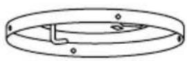
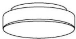
Mounting bracket
natural_image
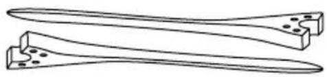
Line drawing of two elongated tools or pliers with holes and a base plate (no text or symbols)Blades
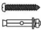
Screws

natural_image
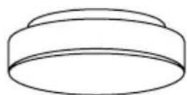
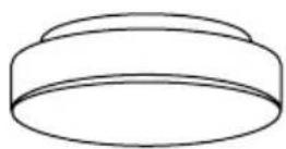
Line drawing of a showerhead with a handle and base (no text or symbols)Motor

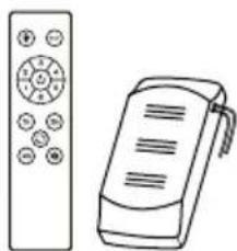
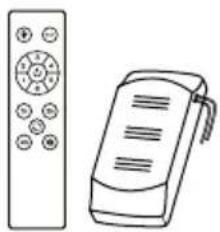
natural_image
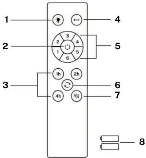
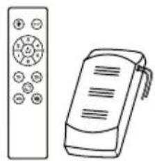
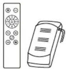
Line drawing of two remote devices: a left-side remote with control buttons and a right-side handheld device (no text or symbols)Remote control & Driver


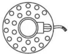
natural_image
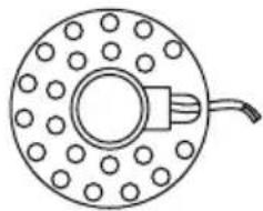
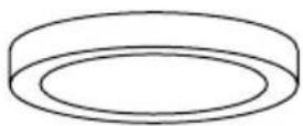
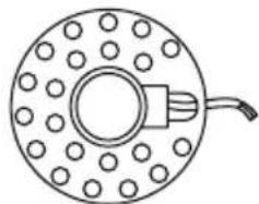
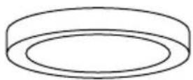
Simple line drawing of a circular mechanical component with evenly spaced holes and a central connector (no text or symbols)LED panelDecorative screen Cor
- Light
- ON/OFF button
- Timer
- Color temperature control
- Fan intensity control
- Reverse function
- Sound off button
- Batteries (2 x AAA)
Controller pairing
- Turn off the main light switch in the room where you have installed your fan for at least 10 seconds.
- Turn the switch on and you will hear a beep, within 3 seconds, press and hold the on/off button until you hear a beep.
- If the pairing process is unsuccessful, repeat the above steps again after turning off the wall switch for at least 1 minute.

LIGHT
Turn the fan light on and off, regardless whether the fan is running or not.

COLOR TEMPERATURE
Alternates between the three types of available light color temperatures (warm, neutral and cool).

ON OFF
Turn the fan on or off completely, regardless whether the light is on or not.

FAN INTENSITY
Increases or decreases the rotation speed of the fan blades.

TIMER
Schedule automatic shutdown by choosing from the available options.

REVERSE FUNCTION
Changes the direction of rotation of the blades fan. The winter function (turn to the right) pushes the hot air accumulated in the ceiling downwards and the summer function (turn to the left) generates a breeze that cools the environment.

DISABLE SOUND
By pressing the sound off button you can silence the sounds that the fan makes when you press any key on the remote control.
INSTALLATION PREPARATION
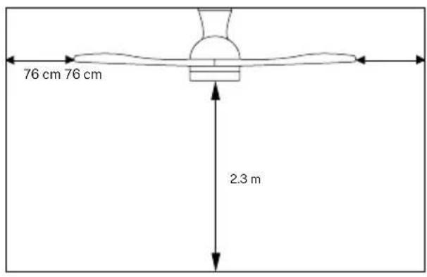
• To avoid personal injury and injury, ensure that the fan is hung in a location that allows the blades to be 2.3 m or more from the floor and 76 cm from the nearest wall or obstacle.
- Make sure the mounting bracket is properly attached to the building structure and can support the full weight of the fan.
FIXING THE MOUNTING BRACKET
- Check that the ceiling where you intend to mount the fan is stable and capable of safely supporting the weight of the fan.
- Do not fix the mounting bracket directly on ceilings less than 10 ~mm to avoid the risk of the screw loosening and coming out.
natural_image
Technical diagram of a mechanical assembly with labeled components and screw holes (no text or symbols)Wood roof
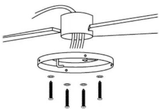
Drill the necessary holes and then secure the mounting bracket with the wood screws and washers to the ceiling joints.
natural_image
Technical line drawing of a ceiling lamp with internal components and mounting base (no text or symbols)Concrete roof
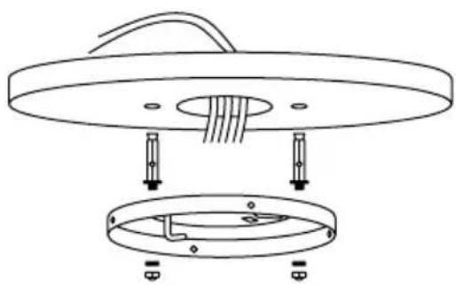
Drill holes with an 8mm drill bit, according to the length of the expansion screws. Next, secure the mounting bracket to the ceiling with the expansion screws.
NOTE: This fan can also be installed in a false ceiling, for this you must use fixing screws with spring lever (not included).
- Mark the correct position of the holes and fix the mounting bracket using the screws with metal anchors or screws and washers suitable for the type of ceiling chosen.
- Verify proper installation of the bracket before hanging the fan. The mounting bracket must support the entire weight of the fan.
WIRING CONNECTION
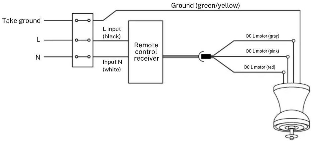
Make the connection between the receiver wires and the fan motor wires following the color indications. Make sure the connection is tight.
flowchart
graph LR
    A["Take ground"] --> B["L input (black)"]
    C["L"] --> B
    D["N"] --> E["Input N (white)"]
    B --> F["Remote control receiver"]
    E --> F
    F --> G["Ground (green/yellow)"]
    G --> H["DC L motor (gray)"]
    G --> I["DC L motor (pink)"]
    G --> J["DC L motor (red)"]
RECEIVER PLACEMENT
natural_image
Line drawing of a mechanical component with a circular head and central shaft (no text or symbols)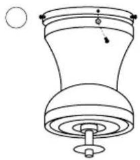
natural_image
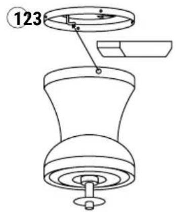
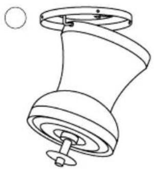
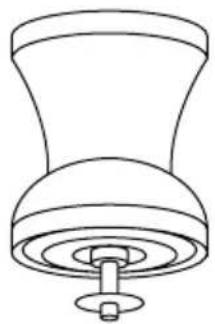
Technical line drawing of a mechanical component with a base and top, showing no text or symbols.- Insert the driver inside the motor body.
- Hook the engine body onto the left hook of the body mount and route the wiring so it does not get pinched.
- Position the motor body so that the holes fit and then screw the 4 body bracket screws to the motor body.
Note: Make sure that the motor body is perfectly installed to the ceiling.
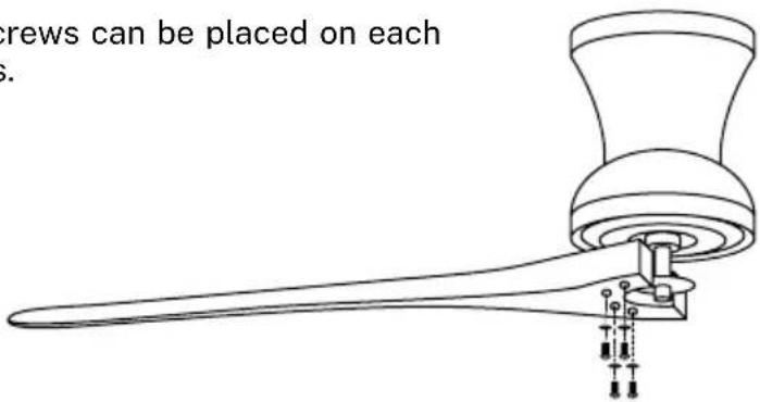
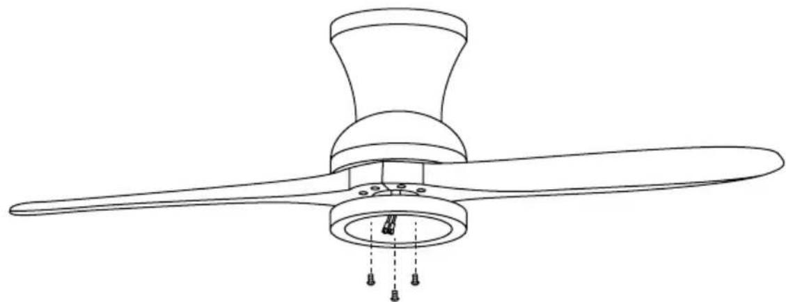
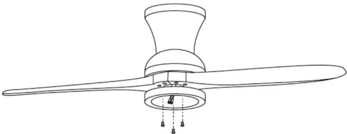
BLADE ASSEMBLY
Advice: Washers for the blade screws can be placed on each screw before installing the blades.
-
Align the blade holes with the screw holes on the motor, and then tighten all the screws. Select the blade screws and attach the first blade, lining up the holes in the motor with the holes in the blade. Screw the blade in so that it is secured but without tightening the screws too much to be able to place the rest.
-
Repeat the previous step with the rest of the blades.
-
Once all the blades are in place, tighten the screws completely so that the blades are fully secured.
natural_image
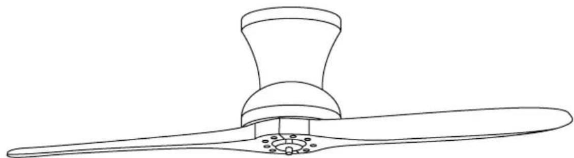
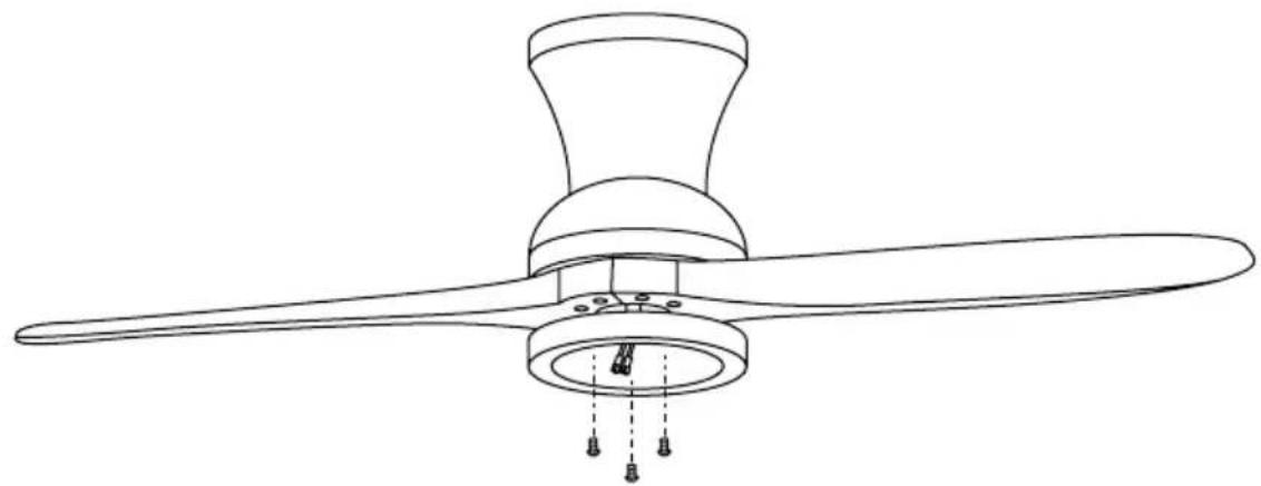
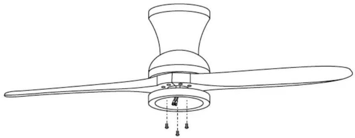
Line drawing of a kitchen fan with a gavel and handle (no text or symbols)LIGHT ASSEMBLY

natural_image
Line drawing of a three-blade propeller with a central hub and mounting holes (no text or symbols)- Unscrew one fixing screw. Fix the patch panel to the bottom of the fan by inserting the other two fixing screw heads into the keyhole slots, rotate it to fit, then secure the previous fixing screw by aligning the screw hole and the keyhole. on the bottom of the fan, tighten the remaining setscrews to secure the connection panel.
natural_image
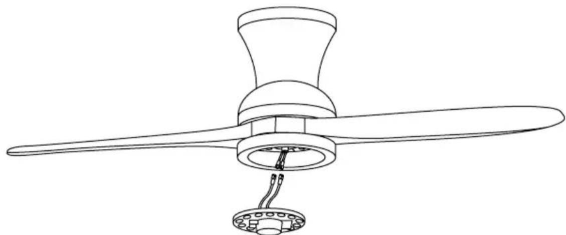
Line drawing of a three-blade propeller with a base mount (no text or symbols)- Connect the single pin plugs on the breakout board to those on the LED panel. The LED panel is magnetized so it attaches to the backplane by simply snapping the two pieces together.
Note: While installing or removing the LED board, be careful not to touch the insulating tabs. Do not overtighten or fasten the screws as this may cause damage to the insulating tabs.
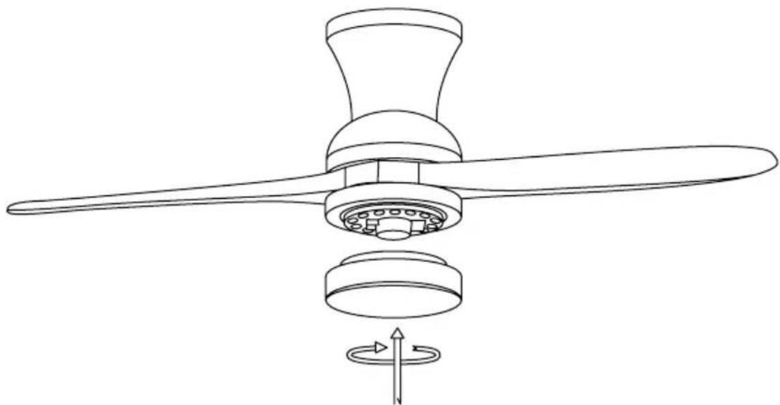
- Thread the decorative shade onto the LED plate and secure with decorative clips and nuts.
natural_image
Line drawing of a three-blade propeller with a rotating base and directional arrow indicating rotation (no text or symbols)CHECK THE INSTALLATION
- Check the correct operation of the fan, checking that there is no strange movement or misalignment in any part of the fan.
- In the event that any type of buzzing/vibration can be noticed, you can adjust the blades with the balance kit that has self-adhesive counterweights and "u" clips. You can put the clip in the center of any blade and check if the vibration decreases.
- Turn on the fan and check. If no change is seen, turn off the fan and add another clip on another blade or use the adhesive weights.
In compliance with the directives: 2012/19/EU and 2015/863/EU on the restriction of the use of hazardous substances in electrical and electronic equipment, as well as their waste disposal. The crossed bin symbol shown on the packaging indicates that the product at the end of its useful life will be collected as separate waste. Therefore, any product that has reached the end of its useful life should be delivered to waste disposal centers specialized in the separate collection of waste electrical and electronic equipment, or returned to the retailer when purchasing similar new equipment, in one for a base. Proper separate collection for subsequent commissioning of equipment sent for recycling, treatment and disposal in an environmentally compatible manner helps prevent possible negative effects on the environment and health and optimizes recycling and reuse of waste. the components that make up the device. The abusive disposal of the product by the user implies the application of administrative sanctions in accordance with the laws.
natural_image
Line drawing of two elongated metal tools with holes and a base (no text or symbols)
Tornillería
natural_image
Line drawing of a showerhead with a handle and base (no text or symbols)Motor

natural_image
Line drawing of a remote control with a separate handheld device (no text or symbols)natural_image
Simple line drawing of a circular component with evenly spaced holes and a central connector (no text or symbols)Pantalla decorativa Panel de conexiones Panel LED
natural_image
Technical diagram of a mechanical assembly with a central component and multiple screws below (no text or symbols)Techo de madera
natural_image
Technical diagram of a mechanical assembly with two views of a circular component (no text or symbols)Techo de hormigón
natural_image
Line drawing of a mechanical component with a circular head and central hub (no text or symbols)
natural_image
Technical line drawing of a mechanical component with a base and mounting hole (no text or symbols)natural_image
Line drawing of a propeller with a gavel resting on it (no text or symbols)MOTNAJE DE LA LUZ
natural_image
Line drawing of a three-blade propeller with mounting holes and a central hub (no text or symbols)natural_image
Line drawing of a three-blade propeller with a base mount (no text or symbols)natural_image
Line drawing of two elongated tools or pliers with holes and a base plate (no text or symbols)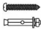
Parafusos
natural_image
Line drawing of a showerhead with a handle and base (no text or symbols)Motor

natural_image
Line drawing of a remote control and a handheld device (no text or symbols)Controle remoto e controlador

natural_image
Simple line drawing of a circular mechanical component with evenly spaced holes and a central connector (no text or symbols)Tela decorativaPainel de conexão Painel de LED
natural_image
Technical diagram of a mechanical assembly with threaded components and a circular base, showing no text or symbols.Telhado de madeira
natural_image
Technical line drawing of a mechanical assembly with two circular components and mounting holes (no text or symbols)Telhado de concreto
natural_image
Line drawing of a mechanical component with a circular head and central hub (no text or symbols)
natural_image
Technical line drawing of a mechanical component with a base and mounting base (no text or symbols)natural_image
Line drawing of a propeller with a flared handle and central hub (no text or symbols)MONTAGEM DE LUZ

natural_image
Line drawing of a three-blade propeller with a central hub and mounting holes (no text or symbols)natural_image
Line drawing of a three-blade propeller with a base mount (no text or symbols)natural_image
Line drawing of a three-blade propeller with internal components and a rotating arrow indicating rotation (no text or symbols)natural_image
Line drawing of two elongated tools or pliers with holes and a base plate (no text or symbols)
Des vis

natural_image
Line drawing of a showerhead with a handle and base (no text or symbols)Moteur
natural_image
Line drawing of a remote control with a separate handheld device (no text or symbols)natural_image
Simple line drawing of a circular component with evenly spaced holes and a central connector (no text or symbols)natural_image
Technical diagram of a mechanical assembly with a central component and multiple screws below (no text or symbols)Toiture en bois
natural_image
Technical line drawing of a ceiling lamp with internal components and mounting base (no text or symbols)Toit en béton
natural_image
Line drawing of a mechanical component with a circular head and central hub (no text or symbols)
natural_image
Technical line drawing of a mechanical component with a base and mounting base (no text or symbols)natural_image
Line drawing of a propeller with a gavel and central hub (no text or symbols)ENSEMBLE LÉGER
natural_image
Line drawing of a three-blade propeller with mounting holes and a central hub (no text or symbols)natural_image
Line drawing of a three-blade propeller with a base mount (no text or symbols)natural_image
Line drawing of a propeller with a rotating base and directional arrow indicating rotation (no text or symbols)VÉRIFIER L'INSTALLATION
natural_image
Line drawing of two elongated tools or pliers with holes and a base plate (no text or symbols)
Viti

natural_image
Line drawing of a showerhead with a handle and base (no text or symbols)Motore
natural_image
Line drawing of a remote control and a handheld device (no text or symbols)Telecomando e controller


natural_image
Technical line drawing of a circular mechanical component with evenly spaced holes and a central connector (no text or symbols)natural_image
Technical diagram of a mechanical assembly with labeled components and screw base (no text or symbols)Tetto in legno
natural_image
Technical line drawing of a ceiling fixture with internal components and mounting holes (no text or symbols)Tetto in cemento
natural_image
Line drawing of a mechanical component with a circular head and central hub (no text or symbols)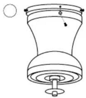
natural_image
Technical line drawing of a mechanical component with a base and mounting base (no text or symbols)natural_image
Line drawing of a propeller with a flared handle and central hub (no text or symbols)ASSEMBLAGGIO LEGGERO
natural_image
Line drawing of a three-blade propeller with a central hub and hanging base (no text or symbols)natural_image
Line drawing of a three-blade propeller with a base mount (no text or symbols)natural_image
Line drawing of a three-blade propeller with a rotating base and directional arrow indicating rotation (no text or symbols)natural_image
Line drawing of a showerhead with a handle and base (no text or symbols)Motor
natural_image
Line drawing of a remote control with a handheld device (no text or symbols)natural_image
Simple line drawing of a circular mechanical component with evenly spaced holes and a central connector (no text or symbols)natural_image
Technical diagram of a mechanical assembly with labeled components (no text or symbols present)Holzdach
natural_image
Technical line drawing of a mechanical assembly with two circular components and mounting holes (no text or symbols)Betondach
natural_image
Line drawing of a mechanical component with a circular head and central hub (no text or symbols)
natural_image
Technical line drawing of a mechanical component with a base and mounting hole (no text or symbols)natural_image
Line drawing of a propeller with a flared handle and central hub (no text or symbols)LICHTMONTAGE

natural_image
Line drawing of a three-blade propeller with a central hub and mounting holes (no text or symbols)natural_image
Line drawing of a three-blade propeller with a base mount (no text or symbols)natural_image
Line drawing of a propeller with a rotating base and directional arrow indicating rotation (no text or symbols)ÜBERPRÜFEN SIE DIE INSTALLATION
natural_image
Line drawing of a showerhead with a central handle and base (no text or symbols)Motor
natural_image
Line drawing of a remote control with a handheld device (no text or symbols)Afstandsbediening en controller
natural_image
Simple line drawing of a circular mechanical component with evenly spaced holes and a central hub (no text or symbols)natural_image
Technical diagram of a mechanical assembly with a central component and multiple screws (no text or symbols)Houten dak
natural_image
Technical line drawing of a ceiling lamp with internal components and mounting base (no text or symbols)Betonnen dak
natural_image
Line drawing of a mechanical component with a circular head and central hub (no text or symbols)
natural_image
Technical line drawing of a mechanical component with a base and mounting base (no text or symbols)natural_image
Line drawing of a propeller with a flared handle and central hub (no text or symbols)LICHTE MONTAGE
natural_image
Line drawing of a three-blade propeller with mounting holes and a central hub (no text or symbols)natural_image
Line drawing of a three-blade propeller with a base mount (no text or symbols)natural_image
Line drawing of a three-blade propeller with a rotating base and directional arrow indicating rotation (no text or symbols)CONTROLEER DE INSTALLATIE
natural_image
Line drawing of two elongated tools or pliers with holes and a base plate (no text or symbols)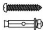
Śruby

natural_image
Line drawing of a showerhead with a handle and base (no text or symbols)Silnik

natural_image
Line drawing of two remote devices: a left-side remote with control buttons and a right-side handheld device (no text or symbols)Pilot i kontroler

natural_image
Technical line drawing of a circular mechanical component with evenly spaced holes and a central connector (no text or symbols)INTENSYWNOŚĆ WENTYLATORA
natural_image
Technical diagram of a mechanical assembly with a central component and three screws, no text or symbols present.Dach drewniany
natural_image
Technical line drawing of a ceiling fixture with mounting holes and internal components (no text or symbols)Betonowy dach
natural_image
Line drawing of a mechanical component with a circular head and central hub (no text or symbols)
natural_image
Technical line drawing of a mechanical component with a base and mounting base (no text or symbols)natural_image
Line drawing of a propeller with a conical top and base, showing internal components (no text or symbols)LEKKI MONTAZ

natural_image
Line drawing of a three-blade propeller with a central hub and mounting holes (no text or symbols)natural_image
Line drawing of a three-blade propeller with a base mount (no text or symbols)natural_image
Line drawing of a three-blade propeller with a rotating base and directional arrow indicating rotation (no text or symbols)SPRAWDŹ INSTALACJĘ

- Wind Prop
- INDEX
- ENGLISH
- PORTUGUÊS
- LOCATION AND INSTALLATION REQUIREMENTS
- MECHANIC TIPS
- ELECTRICAL TIPS
- LIST OF PARTS
- Controller pairing
- LIGHT
- COLOR TEMPERATURE
- ON OFF
- FAN INTENSITY
- TIMER
- REVERSE FUNCTION
- DISABLE SOUND
- INSTALLATION PREPARATION
- FIXING THE MOUNTING BRACKET
- WIRING CONNECTION
- RECEIVER PLACEMENT
- BLADE ASSEMBLY
- CHECK THE INSTALLATION
- VÉRIFIER L'INSTALLATION
- ÜBERPRÜFEN SIE DIE INSTALLATION
- CONTROLEER DE INSTALLATIE
- INTENSYWNOŚĆ WENTYLATORA
- LEKKI MONTAZ
- SPRAWDŹ INSTALACJĘ
Brand : Create
Model : WIND PROP
Category : Fan