
C8FSE - Saw HiKOKI - Free user manual and instructions
Find the device manual for free C8FSE HiKOKI in PDF.

| Product type | Radial miter saw |
| Brand | HiKOKI |
| Model | C8FSE |
| Dimensions (L × W × H) | 555 mm × 790 mm × 485 mm |
| Net weight | 16.4 kg |
| Power supply | 110 V or 230 V ~ (depending on region), 1050 W |
| No-load speed | 5500 min⁻¹ |
| Blade diameter | 216 mm |
| Blade arbor | 30 mm |
| Blade thickness | 2 mm |
| Maximum kerf | 2.7 mm |
| Miter angle | Right 0° to 57°, Left 0° to 45° |
| Bevel angle | Right 0° to 5°, Left 0° to 48° |
| Max cutting capacity (0°) | 65 mm × 312 mm |
| Max cutting capacity (45° miter) | 65 mm × 220 mm |
| Main functions | Miter cut, bevel cut, compound cut, sliding cut, groove cutting, laser guide (model C8FSHE) |
| Included accessories | TCT blade 216 mm, dust bag, 10 mm wrench, vice assembly, support, side handle, safety barrier, sub-table |
| Laser class (C8FSHE) | Class II, < 3 mW, 654 nm |
| Sound pressure level | 96 dB(A) (uncertainty K=3 dB(A)) |
| Sound power level | 105 dB(A) (uncertainty K=3 dB(A)) |
| Maintenance and cleaning | Clean with a damp soapy cloth, blow off chips with dry air, grease sliding surfaces once a month |
| Safety | Lower guard, saw head lock, lock-off switch, blade brake |
| Spare parts and repairability | Replaceable carbon brushes, interchangeable saw blade, repairs only by HiKOKI authorized service center |
| Warranty | Complies with national regulations, does not cover normal wear or misuse |
Frequently Asked Questions - C8FSE HiKOKI
User questions about C8FSE HiKOKI
0 question about this device. Answer the ones you know or ask your own.
Ask a new question about this device
Download the instructions for your Saw in PDF format for free! Find your manual C8FSE - HiKOKI and take your electronic device back in hand. On this page are published all the documents necessary for the use of your device. C8FSE by HiKOKI.
USER MANUAL C8FSE HiKOKI
natural_image
Technical line drawing of a mechanical cutting machine with no visible text or symbolsC8FSHE

en Handling instructions
de Bedienungsanleitung
fr Mode d'emploi
it Istruzioni per l'uso
nl Gebruiksaanwijzing
es Instrucciones de manejo
pt Instruções de uso

1
2
3
6
7
a
8
b
9
10
11 12
13 14
15
16 17
18
natural_image
Technical line drawing of a mechanical clamp or bracket with a curved arrow indicating direction (no text or symbols)
LASER RADIATION
DO NOT VIEW DIRECTLY WITH OPTICAL INSTRUMENTS
INSTRUMENTS
CLASS 1M LASER PRODUCT
Po < 0.4mW, Ce=1, (lambda)=654nm, Time basis 100s
Standard: IEC 60825-1:2007
C3299933
natural_image
Medical illustration showing surgical procedure with surgical instruments and a black arrow indicating direction (no text or labels)
AVOID EXPOSURE
Laser radiation
is emitted from
this aperture.
CAUTION
Laser radiation when open.
Do not view directly with
optical instruments. c3528112
19 20
21
22 23
natural_image
Technical line drawing of a mechanical cutting tool with a circular component and tool path (no text or symbols)31 32
33
34
35
| 98 | |
| 110V 21 | |
| 230V 01 |
natural_image
Technical line drawing of a mechanical component with a numbered annotation (96), no readable text or symbols present.36 37
natural_image
Technical line drawing of a mechanical assembly with a hand adjusting a component (no text or symbols present)| English Deutsch Français | |||
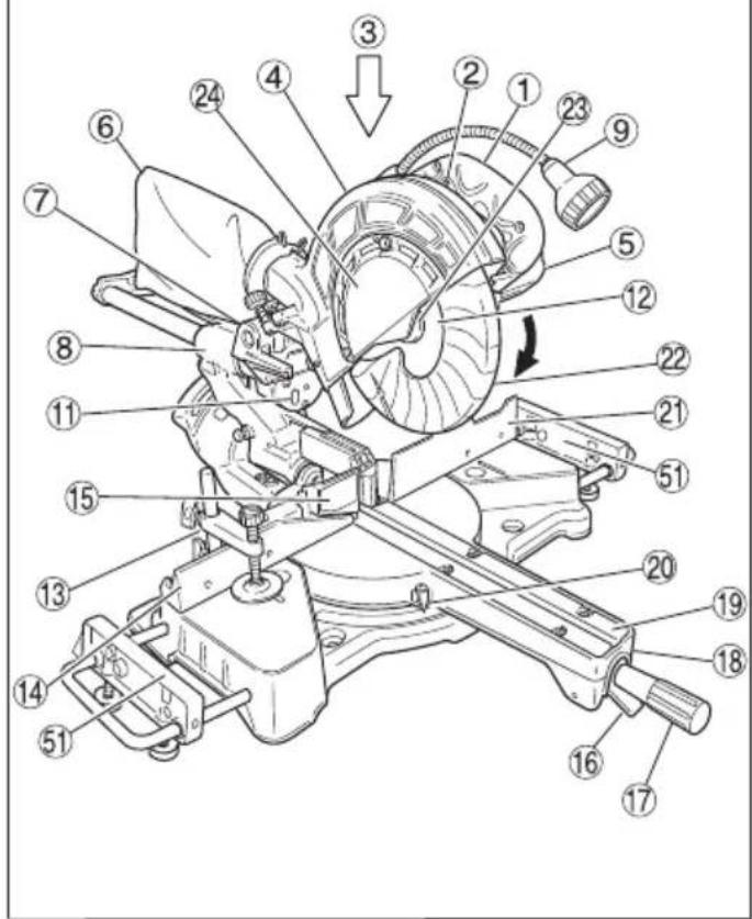
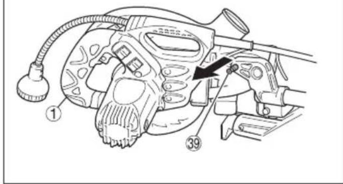
| 1 | Handle Griff | Poignée | |
| 2 | Lock-off button Sperrtaste Bouton de verrouillage | ||
| 3 | Motor Head Motorkopf Tête de moteur | ||
| 4 | Gear Case Getriebegehäuse Réducteur | ||
| 5 | Motor Motor Moteur | ||
| 6 | Dust Bag Staubbeutel Bacquet de réception des copeaux | ||
| 7 | Hinge Scharnier Charnière | ||
| 8 | Holder (A) Halter (A) Support (A) | ||
| 9 | Light (Only C8FSHE) | Licht (Nur C8FSHE) | Lumière (C8FSHE seulement) |
| 10 | Indicator (For bevel scale) | Anzeige (Für Fasenskala) | Indicateur (Pour l'échelle de biseau) |
| 11 | Laser Marker(Only C8FSHE) | Lasermarkierer(Nur C8FSHE) | Marqueur à laser(C8FSHE seulement) |
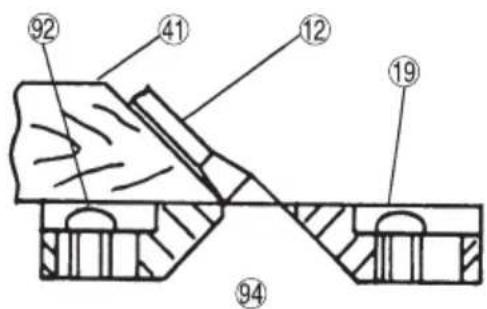
| 12 | Saw Blade Sägeblatt | Lame de scie | |
| 13 | Vise Assembly | Schraubstocksatz | Ensemble d'étau |
| 14 | Fence (B) | Gitter (B) | Guide (B) |
| 15 | Sub Fence Hilfsführung Guide auxiliaire | ||
| 16 | Lever | Hebel Levier | |
| 17 | Side Handle | Seitengriff | Poignée latérale |
| 18 | Turntable | Drehbühne | Plaque tournante |
| 19 | Table Insert Tischeinsatz | Plaque d'insertion | |
| 20 | Indicator (For miter scale) | Zeiger (Für Gehrungsskala) | Indicateur (Pour l'échelle d'onglet) |
| 21 | Fence (A) | Gitter (A) | Guide (A) |
| 22 | Lower Guard | Unterer Schutz Guide inférieur | |
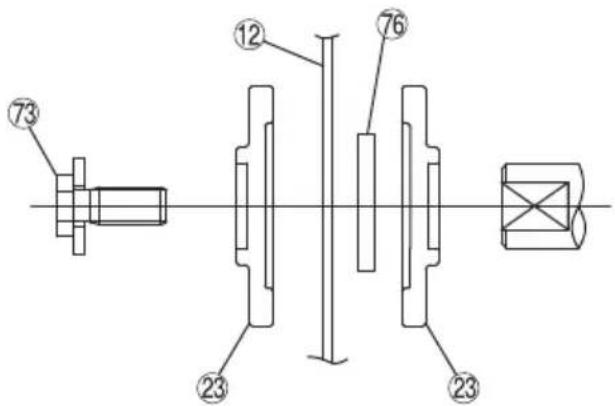
| 23 | Washer (D) | Unterlegscheibe (D) | Rondelle (D) |
| 24 | Spindle Cover | Spindelabdeckung | Couvercle de l'arbre |
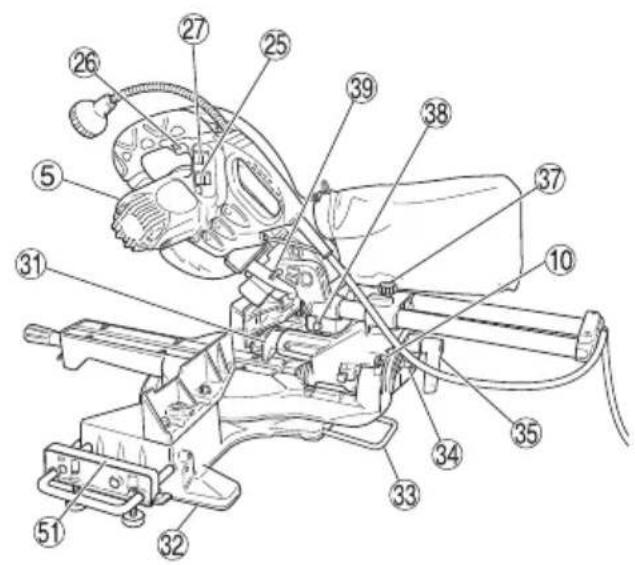
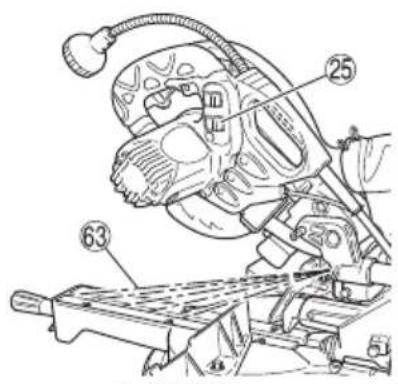
| 25 | Switch (For laser marker)(Only C8FSHE) | Schalter (Für Lasermarkierer)(Nur C8FSHE) | Interrupteur (Pour marqueur à laser)(C8FSHE seulement) |
| 26 | Trigger Switch | Auslöserschalter | Interrupteur à détente |
| 27 | Switch (For light)(Only C8FSHE) | Lichtschalter(Nur C8FSHE) | Interrupteur (Pour la lumière)(C8FSHE seulement) |
| 28 | Marking (Pre-marked) | Markierung (vormarkiert) | Marquage (pré-marqué) |
| 29 | Spindle Lock | Spindelhebel | Verrou en fuseau |
| 30 | 6 mm Flat Head Screw | 6 mm Flachkopfschraube | Vis à tête plate de 6 mm |
| 31 | Guard | Schutz | Protection |
| 32 | Base | Grundplatte Socle | |
| 33 | Holder | Halter | Support |
| 34 | Set pin | Fixierstift | Goupille de réglage |
| 35 | Clamp Lever | Klemmhebel | Levier de serrage |
| 36 | 6 mm Depth Adjustment Bolt | 6 mm Tiefenstellschraube | Boulon de réglage de la profondeurde 6 mm |
| 37 | Slide Securing Knob | Führungssicherungsknopf | Bouton de fixation du chariot |
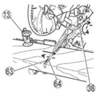
| 38 | Adjuster (For laser marker)(Only C8FSHE) | Einstellung(Für Lasermarkierer)(Nur C8FSHE) | Ajusteur (Pour marqueur à laser)(C8FSHE seulement) |
| 39 | Locking Pin | Verriegelungsstift | Goupille de verrouillage |
| 40 | 6 mm Bolt | 6-mm-Schraube | Boulon 6 mm |
| 41 | Workpiece Werkstück | Pièce | |
| 42 | Auxiliary Board | Hilfsbrett | Carte auxiliaire |
| 43 | 8 mm Depth Adjustment Bolt 8 mm Tiefenstellschraube | Boulon de réglage de profondeur de 8 mm | |
| 44 | 6 mm Nut 6 mm Schraubenmutter Ecrou de 6 mm | ||
| 45 | 6 mm Knob Bolt Knopfschraube, 6 mm | Vis moletée de 6 mm | |
| 46 | Holder Halter Support | ||
| 47 | Steel Square Stahlwinkel Equerre en acier | ||
| 48 | 6mm Machine Screw 6-mm-Maschinenschraube Vis à métaux 6 mm | ||
| 49 | Height Adjustment Bolt 8 mm Höheneinstellschraube, 8 mm | Boulon de réglage de la hauteur de 8 mm | |
| 50 | Base Surface | Grundfläche | Surface du socle |
| 51 | Sub table | Untertisch | Sous-table |
| 52 | 6 mm Wing Bolt | 6-mm-Flügelschraube | Boulon à oreilles 6 mm |
| 53 | Line | Linie | Ligne |
| 54 | Warning Sign Warnzeichen | Panneau de signalisation | |
| 55 | Screw Holder Schraubenhalter | Support de vis | |
| 56 | 6 mm Wing Bolt (B) | 6-mm-Flügelschraube (B) | Boulon à oreilles de 6 mm (B) |
| 57 | Vise Shaft | Schraubstockachse | Arbre d’étau |
| 58 | Light lens Lichtlinse | Lentille lumineuse | |
| 59 | Fence | Gitter | Guide |
| 60 | 6 mm Wing Bolt (A) | 6-mm-Flügelschraube (A) | Boulon à oreilles de 6 mm (A) |
| 61 | Vise Plate | Schraubstockbacke | Talon |
| 62 | Knob | Knopf Bouton | |
| 63 | Laser line Laserlinie Raie laser | ||
| 64 | Groove | Nut | Rainure |
| 65 | Bevel Scale | Schrägschnittskala | Echelle de biseau |
| 66 | Miter Scale | Gehrungsskala | Echelle d’onglet |
| 67 | Crown molding Vise Ass’y(Optional accessory) | Schraubstocksatz für Kronenform(Sonderzubehör) | Ensemble d’étau de corniche à courbe complexe(Accessoire en option) |
| 68 | 6 mm Wing Nut(Optional accessory) | Flügelmutter, 6 mm (Sonderzubehör) | Ecrou à ailettes de 6 mm(Accessoire en option) |
| 69 | Crown molding Stopper (L)(Optional accessory) | Kronenformanschlag (L)(Sonderzubehör) | Butée de corniche à courbe complexe (L) (Accessoire en option) |
| 70 | Crown molding Stopper (R)(Optional accessory) | Kronenformanschlag (R)(Sonderzubehör) | Butée de corniche à courbe complexe (R) (Accessoire en option) |
| 71 | Crown molding | Kronenform | Corniche à courbe complexe |
| 72 | 10 mm Box Wrench | 10 mm Steckschüssel | Clé à écrous de 10 mm |
| 73 | Bolt | Schraube Boulon | |
| 74 | Light | Licht | Lumière |
| 75 | Wear limit line | Verschleißgrenze | Repère de limite d’usure |
| 76 | Collar (A) | Manschette (A) | Collier (A) |
| 77 | 6 mm Knob Bolt Knopfschraube, 6 mm | Vis moletée de 6 mm | |
| 78 | Duct | Kanal | Conduit |
| 79 | Right angle Rechter Winkel | Angle droit | |
| 80 | Dust extractor | Staub-Absaugung | Extracteur de poussière |
| 81 | Hose (id 38 mm × 3 m long) | Schlauch (id 38 mm × 3 m lang) | Tuyau (38 mm id × 3 m de long) |
| 82 | Adapter (Dust extractor’s standardaccessory)English Deutsch Français | Adapter (Staub-AbsaugungStandard-Zubehör) | Adaptateur (accessoire standardd'extracteur de poussière) |
| 83 | Joint (Optional accessory) Gelenk (Sonderzubehör) Joint (accessoire en option) | ||
| 84 | Dust collection adapter(Optional accessory) | Staubsammler-Adapter(Sonderzubehör) | Adaptateur de collecte de poussière(accessoire en option) |
| 85 | Hose band (Optional accessory) Schlauchschelle (Sonderzubehör) | Collier de serrage de tuyau(accessoire en option) | |
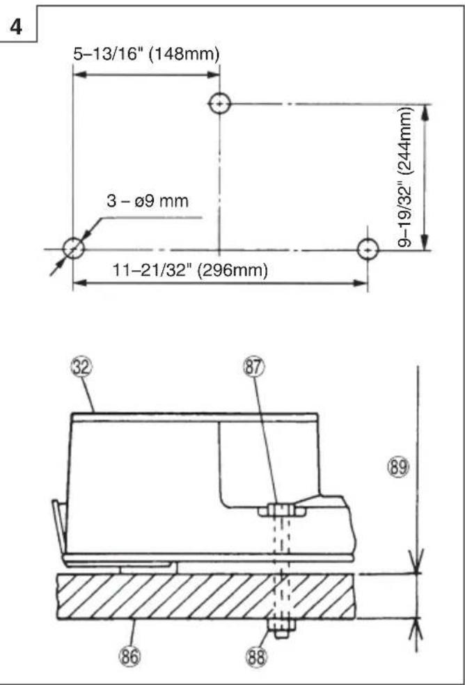
| 86 | Work bench Werkbank Établi | ||
| 87 | 8 mm Bolt 8-mm-Schraube Boulon 8 mm | ||
| 88 | 8 mm Nut 8 mm Schraubenmutter Ecrou de 8 mm | ||
| 89 | 25 mm thick bench 25 mm dicke Sitzbank 25 mm d'épaisseur de banc | ||
| 90 | 8 mm Bolt (B)(Stopper for left 45° bevel angle) | 8 mm Bolzen (B) (Stopper für linken45° abgeschrägten Winkel) | Boulon 8 mm (B)(Butée pour un angle de biseaugauche de 45°) |
| 91 | 8 mm Bolt (A) (Stopper for 0°) 8 mm Bolzen (A) (Stopper für 0°) Boulon 8 mm (A) (Butée pour 0°) | ||
| 92 | 6 mm Machine screw 6 mm Maschinenschraube Vis d'assemblage 6 mm | ||
| 93 | Right angle cutting | Rechter Winkel Schneiden | Coupe angle droit |
| 94 | Left bevel angle cutting | Linker abgeschrägter WinkelSchneiden | Coupe en biseau de l'angle gauche |
| 95 | 6 mm Bolt 6-mm-Schraube Boulon 6 mm | ||
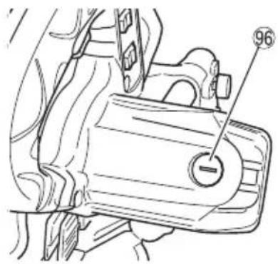
| 96 | Brush cap Bürstenkappe | Capuchon de balais | |
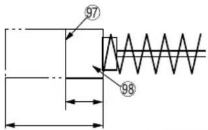
| 97 | Wear limit | Verschleißgrenze | Limite d'usure |
| 98 | No. of carbon brush | Nr. der Kohlebürste | No. du balai en carbone |
| 99 | Air gun | Druckluftpistole | Pistolet à air |
| 100 | Carry Handle | Tragegriff | Poignée de transport |
| 101 | Base Grip | Basisgriff | Poignée de base |
| 102 | Piece of wood to secure the vice | Stück Holz zur Sicherung desSchraubstocks | Morceau de bois pour fixer l'étau |
| Italiano Nederlands Español | |||
| 1 | Manico Greep Empuñaradura | ||
| 2 | Pulsante di sblocco Ontgrendelingsknop Botón de desbloqueo | ||
| 3 | Testa motore Motorkop Cabezal del motor | ||
| 4 | Cassa ingranaggi Tandwielkast Caja de engranajes | ||
| 5 | Motore Motor Motor | ||
| 6 | Raccoglipolvere Stofzak Bolsa para el polvo | ||
| 7 | Cardine Scharnier Bisagra | ||
| 8 | Supporto (A) Houder (A) | Soporte (A) | |
| 9 | Luce (Solo C8FSHE) | Lamp (Alleen C8FSHE) | Luz (Sólo C8FSHE) |
| 10 | Indicatore (Per scala di smussatura) | Indicator (Voor afschuiningsschaal) | Indicador (Para escala de bisel) |
| 11 | Marcatore laser (Solo C8FSHE) | Lasermarkeerinrichting (Alleen C8FSHE) | Marcador láser (Sólo C8FSHE) |
| 12 | Lama sega | Zaagblad Cuchilla de sierra | |
| 13 | Gruppo morsa | Bankschroef | Conjunto del tornillo de carpintero |
| 14 | Guida de appoggio (B) | Geleider (B) | Protección (B) |
| 15 | Guida secondaria | Sub-geleider Tope-guía secundario | |
| 16 | Leva | Hendel | Palanca |
| 17 | Manico laterale | Zijgreep | Asa lateral |
| 18 | Piatto girevole | Draaitafel Plataforma | |
| 19 | Inserimento tavola | Tafel-inzetstuk | Inserto de mesa |
| 20 | Indicatore (Per la scala di quartabuono) | Indicator (Voor verstekschaal) | Indicador (Para escala de ingletes) |
| 21 | Guida de appoggio (A) | Geleider (A) | Protección (A) |
| 22 | Protezione inferiore Onderste afscherming | Protector inferior | |
| 23 | Rondella (D) | Sluitring (D) | Arandela (D) |
| 24 | Coperchio dell'alberino | Drijfas-afdekking | Cubierta de husillo |
| 25 | Interruttore (Per marcatore laser) (Solo C8FSHE) | Schakelaar (Voor lasermarkeerinrichting) (Alleen C8FSHE) | Interruptor (Para marcador láser) (Sólo C8FSHE) |
| 26 | Interruttore a grilletto | Startschakelaar | Gatillo |
| 27 | Interruttore (Per luce) (Solo C8FSHE) | Schakelaar (Voor lamp) (Alleen C8FSHE) | Interruptor (Para luz) (Sólo C8FSHE) |
| 28 | Marcatura (pre-contrassegnato) | Markering (voorgemarkeerd) | Marcaje (pre-marcado) |
| 29 | Fermo dell'alberino | Spilvergrendeling Seguro del eje | |
| 30 | Vite a testa piatta 6 mm | 6 mm schroef met platte kop | Tornillo de cabeza plana 6 mm |
| 31 | Schermo protettivo | Bescherming Protector | |
| 32 | Base | Basis | Base |
| 33 | Supporto | Houder Soporte | |
| 34 | Perno di impostazione | Instelpen | Pasador de fijación |
| 35 | Leva morsetto | Klemhendel | Palanca de fijación |
| 36 | Bullone di regolazione della profondità 6 mm | 6 mm diepte-afstelbout | Perno de ajuste de profundidad 6mm |
| 37 | Manopola di fissaggio slitta | Schuifvastzetknop | Perilla de inmovilización de deslizamiento |
| 38 | Regolatore (Per marcatore laser) (Solo C8FSHE) | Afsteller (Voor lasermarkeerinrichting) (Alleen C8FSHE) | Ajustador (Para marcador láser) (Sólo C8FSHE) |
| 39 | Perno di blocco | Vergrendelpen | Pasador de bloqueo |
| 40 | Bullone da 6 mm | 6 mm bout | Perno de 6 mm |
| 41 | Pezzo da lavorare Werkstuk Pieza de trabajo | ||
| 42 | Pannello ausiliario Hulpplaat Panel auxiliar | ||
| 43 | Bullone di regolazione profondità da 8 mm | 8 mm diepte-stelbout | Perno de ajuste de profundidad de 8 mm |
| 44 | Dado 6 mm 6 mm moer Tuerca 6 mm | ||
| 45 | Bullone a manopola da 6 mm 6 mm knopbout Perno de perilla de 6 mm | ||
| 46 | Supporto | Houder | Soporte |
| 47 | Quadrato di acciaio Stalen winkelhaak | Escuadra de acero | |
| 48 | Vite da macchina da 6 mm 6 mm machineschroef Tornillo de la máquina de 6 mm | ||
| 49 | Bullone di regolazione altezza da 8 mm | Hoogte-afstelbout 8 mm Perno de ajuste de altura de 8 mm | |
| 50 | Superficie della base | Voetplaat | Superficie de la base |
| 51 | Tavola secondaria | Subtafel | Mesa secundaria |
| 52 | Bullone ad alette da 6 mm | 6 mm vleugelmoer | Perno de aletas de 6 mm |
| 53 | Riga | Streep | Cuerda |
| 54 | Segnale di avvertimento Waarschuwingssymbool | Signo de advertencia | |
| 55 | Portavite | Schroefhouder | Sujetador de rosca |
| 56 | 6 mm vite ad alette (B) | 6 mm vleugelbout (B) | 6 mm perno de ala (B) |
| 57 | Albero della morsa Bankschroefas | Eje de tornillo de banco | |
| 58 | Lente della luce | Lamplens Lente de luz | |
| 59 | Guida di appoggio | Geleider | Protrección |
| 60 | 6 mm vite ad alette (A) | 6 mm vleugelbout (A) | 6 mm perno de ala (A) |
| 61 | Piastra morsa | Klemplaat | Placa de tornillo |
| 62 | Manopola | Knop | Perilla |
| 63 | Linea laser | Laserstreep | Línea de láser |
| 64 | Scanalatura | Groef | Ranura |
| 65 | Scala di smussatura | Afschuinschaal | Escala en bisel |
| 66 | Scala di quartabuono | Verstekschaal | Escala de ingletes |
| 67 | Gruppo morsa di modanatura a corona (Accessorio opzionale) | Kroonvormklem (Optioneel toebehoren) | Conj. de tornillo de carpintero para moldura en vértice (Accesorio opcional) |
| 68 | Dado ad alette da 6 mm (Accessorio opzionale) | 6 mm vleugelmoer (Optioneel toebehoren) | Tuerca de aletas de 6 mm (Accesorio opcional) |
| 69 | Fermo per modanatura a corona (L) (Accessorio opzionale) | Kroonvormstopper (L) (Optioneel toebehoren) | Retén de moldura en vértice (L) (Accesorio opcional) |
| 70 | Fermo per modanatura a corona (R) (Accessorio opzionale) | Kroonvormstopper (R) (Optioneel toebehoren) | Retén de moldura en vértice (R) (Accesorio opcional) |
| 71 | Modanatura a corona | Kroonvorm | Moldura en vértice |
| 72 | Chiave chisa de 10 mm | 10 mm naafbussleutel | Llave de tubo de 10 mm |
| 73 | Bullone | Schroef | Perno |
| 74 | Luce | Lamp | Luz |
| 75 | Riga di limite usura | Slijtagegrens | Línea de límite de desgaste |
| 76 | Collarino (A) | Kraag (A) | Casquillo (A) |
| 77 | Bullone a manopola da 6 mm 6 mm knopbout | Perno de perilla de 6 mm | |
| 78 | Dotto | Leiding | Conducto |
| 79 | Angolo destro | Juiste hoek | Ángulo recto |
| 80 | Estrattore polvere | Stofafzuiger | Extractor de polvo |
| 81 | Tubo fl essibile(38 mm × 3 m di lunghezza) | Slang (id 38 mm × 3 m lang) | Manguera(id 38 mm × 3 m de longitud) |
| 82 | Adattatore (accessorio standard dell'estrattore polvere) | Adapter (standaardacceissoire stofafzuigunit) | Adaptador (accesorio estándar del extractor de polvo) |
| 83 | Giunto (accessorio opzionale) Verbinding | (Acople (Accesorio opcional) | |
| 84 | Adattatore raccolta polvere (accessorio opzionale) | Stofverzameladapter (Optioneel toebehoren) | Adaptador de recolección de polvo (Accesorio opcional) |
| 85 | Fascetta stringitubo (accessorio opzionale) | Slangband (Optioneel toebehoren) Abrazadera (Accesorio opcional) | |
| 86 | Banco di lavoro Werkbank Banco de trabajo | ||
| 87 | Bullone da 8 mm 8 mm bout Perno de 8 mm | ||
| 88 | Dado 8mm 8 mm moer Tuerca 8 mm | ||
| 89 | Banco da 25 mm di spessore 25 mm dikke bank Banco de 25 mm de grosor | ||
| 90 | Bullone da 8 mm (B) (fermo per angolo di smussatura sinistro a 45°) | 8 mm bout (B)(Stopper voor links 45° hellingshoek) | Perno de 8 mm (B) (Tope para el ángulo de biselado izquierdo de 45°) |
| 91 | Bullone da 8 mm (A) (fermo per 0°) 8 mm bout (A) (stopper voor 0°) Perno de 8 mm (A) (Tope para 0°) | ||
| 92 | Vite da macchina da 6 mm 6 mm machineschroef Tornillo de la máquina de 6 mm | ||
| 93 | Taglio angolo destro | Juiste hoek snijden | Corte de ángulo recto |
| 94 | Taglio angolo di smussatura sinistro | Linkse hellingshoeksnijden | Corte en ángulo de biselado izquierdo |
| 95 | Bullone da 6 mm 6 mm bout Perno de 6 mm | ||
| 96 | Tappo della spazzola | Borstelkap | Protección de cepillo |
| 97 | Limite di usura | Slijtagegrens | Límite de uso |
| 98 | N. della spazzola di carbone | Nr. van de koolborstel | No. de carbón de contacto |
| 99 | Pistola ad aria compressa | Persluchtspuit | Pistola de aire |
| 100 | Manico di trasporto | Draaggreep | Asa de transporte |
| 101 | Impugnatura di base | Basisgreep | Empuñadura de base |
| 102 | Pezzo di legno per fi ssare la morsa | Stuk hout om de bankschroef vast te zetten | Pieza de madera para fi jar el tornillo de banco |
Read all safety warnings, instructions, illustrations and specifications provided with this power tool.
Failure to follow all instructions listed below may result in electric shock, fi re and/or serious injury.
Save all warnings and instructions for future reference.
The term “power tool” in the warnings refers to your mains-operated (corded) power tool or battery-operated (cordless) power tool.
1) Work area safety
a) Keep work area clean and well lit. Cluttered or dark areas invite accidents
b) Do not operate power tools in explosive atmospheres, such as in the presence of fl ammable liquids, gases or dust.
Power tools create sparks which may ignite the dust or fumes.
c) Keep children and bystanders away while operating a power tool.
Distractions can cause you to lose control.
2) Electrical safety
a) Power tool plugs must match the outlet. Never modify the plug in any way. Do not use any adapter plugs with earthed (grounded) power tools.
Unmodifi ed plugs and matching outlets will reduce risk of electric shock.
b) Avoid body contact with earthed or grounded surfaces, such as pipes, radiators, ranges and refrigerators.
There is an increased risk of electric shock if your body is earthed or grounded.
c) Do not expose power tools to rain or wet conditions.
Water entering a power tool will increase the risk of electric shock.
d) Do not abuse the cord. Never use the cord for carrying, pulling or unplugging the power tool.
Keep cord away from heat, oil, sharp edges or moving parts.
Damaged or entangled cords increase the risk of electric shock.
e) When operating a power tool outdoors, use an extension cord suitable for outdoor use.
Use of a cord suitable for outdoor use reduces the risk of electric shock.
f) If operating a power tool in a damp location is unavoidable, use a residual current device (RCD) protected supply.
Use of an RCD reduces the risk of electric shock.
3) Personal safety
a) Stay alert, watch what you are doing and use common sense when operating a power tool. Do not use a power tool while you are tired or under the influence of drugs, alcohol or medication.
A moment of inattention while operating power tools may result in serious personal injury.
b) Use personal protective equipment. Always wear eye protection.
Protective equipment such as a dust mask, non-skid safety shoes, hard hat or hearing protection used for appropriate conditions will reduce personal injuries.
c) Prevent unintentional starting. Ensure the switch is in the off -position before connecting to power source and/or battery pack, picking up or carrying the tool.
Carrying power tools with your finger on the switch or energising power tools that have the switch on invites accidents.
d) Remove any adjusting key or wrench before turning the power tool on.
A wrench or a key left attached to a rotating part of the power tool may result in personal injury.
e) Do not overreach. Keep proper footing and balance at all times.
This enables better control of the power tool in unexpected situations.
f) Dress properly. Do not wear loose clothing or jewellery. Keep your hair and clothing away from moving parts.
Loose clothes, jewellery or long hair can be caught in moving parts.
g) If devices are provided for the connection of dust extraction and collection facilities, ensure these are connected and properly used.
Use of dust collection can reduce dust-related hazards.
h) Do not let familiarity gained from frequent use of tools allow you to become complacent and ignore tool safety principles.
A careless action can cause severe injury within a fraction of a second.
4) Power tool use and care
a) Do not force the power tool. Use the correct power tool for your application.
The correct power tool will do the job better and safer at the rate for which it was designed.
b) Do not use the power tool if the switch does not turn it on and off.
Any power tool that cannot be controlled with the switch is dangerous and must be repaired.
c) Disconnect the plug from the power source and/or remove the battery pack, if detachable, from the power tool before making any adjustments, changing accessories, or storing power tools.
Such preventive safety measures reduce the risk of starting the power tool accidentally.
d) Store idle power tools out of the reach of children and do not allow persons unfamiliar with the power tool or these instructions to operate the power tool.
Power tools are dangerous in the hands of untrained users.
e) Maintain power tools and accessories. Check for misalignment or binding of moving parts, breakage of parts and any other condition that may affect the power tool's operation. If damaged, have the power tool repaired before use.
Many accidents are caused by poorly maintained power tools.
f) Keep cutting tools sharp and clean.
Properly maintained cutting tools with sharp cutting edges are less likely to bind and are easier to control.
g) Use the power tool, accessories and tool bits etc. in accordance with these instructions, taking into account the working conditions and the work to be performed.
Use of the power tool for operations different from those intended could result in a hazardous situation.
h) Keep handles and grasping surfaces dry, clean and free from oil and grease.
Slippery handles and grasping surfaces do not allow for safe handling and control of the tool in unexpected situations.
5) Service
a) Have your power tool serviced by a qualified repair person using only identical replacement parts.
This will ensure that the safety of the power tool is maintained.
PRECAUTION
Keep children and infi rm persons away.
When not in use, tools should be stored out of reach of children and infi rm persons.
SAFETY INSTRUCTIONS FOR MITER SAW
a) Miter saws are intended to cut wood or wood-like products, they cannot be used with abrasive cut-off wheels for cutting ferrous material such as bars, rods, studs, etc.
Abrasive dust causes moving parts such as the lower guard to jam. Sparks from abrasive cutting will burn the lower guard, the kerf insert and other plastic parts.
b) Use clamps to support the workpiece whenever possible. If supporting the workpiece by hand, you must always keep your hand at least 100 mm from either side of the saw blade. Do not use this saw to cut pieces that are too small to be securely clamped or held by hand.
If your hand is placed too close to the saw blade, there is an increased risk of injury from blade contact.
c) The workpiece must be stationary and clamped or held against both the fence and the table. Do not feed the workpiece into the blade or cut "freehand" in any way.
Unrestrained or moving workpieces could be thrown at high speeds, causing injury.
d) Push the saw through the workpiece. Do not pull the saw through the workpiece. To make a cut, raise the saw head and pull it out over the workpiece without cutting, start the motor, press the saw head down and push the saw through the workpiece.
Cutting on the pull stroke is likely to cause the saw blade to climb on top of the workpiece and violently throw the blade assembly towards the operator.
e) Never cross your hand over the intended line of cutting either in front or behind the saw blade.
Supporting the workpiece “cross handed” i.e. holding the workpiece to the right of the saw blade with your left hand or vice versa is very dangerous.
f) Do not reach behind the fence with either hand closer than 100 mm from either side of the saw blade, to remove wood scraps, or for any other reason while the blade is spinning.
The proximity of the spinning saw blade to your hand may not be obvious and you may be seriously injured.
g) Inspect your workpiece before cutting. If the workpiece is bowed or warped, clamp it with the outside bowed face toward the fence. Always make certain that there is no gap between the workpiece, fence and table along the line of the cut.
Bent or warped workpieces can twist or shift and may cause binding on tile spinning saw blade while cutting. There should be no nails or foreign objects in the workpiece.
h) Do not use the saw until the table is clear of all tools, wood scraps, etc., except for the workpiece.
Small debris or loose pieces of wood or other objects that contact the revolving blade can be thrown with high speed.
i) Cut only one workpiece at a time.
Stacked multiple workpieces cannot be adequately clamped or braced and may bind on the blade or shift during cutting.
j) Ensure the miter saw is mounted or placed on a level, fi rm work surface before use.
A level and firm work surface reduces the risk of the miter saw becoming unstable.
k) Plan your work. Every time you change the bevel or miter angle setting, make sure the adjustable fence is set correctly to support the workpiece and will not interfere with the blade or the guarding system.
Without turning the tool "ON" and with no workpiece on the table, move the saw blade through a complete simulated cut to assure there will be no interference or danger of cutting the fence.
I) Provide adequate support such as table extensions, saw horses, etc. for a workpiece that is wider or longer than the table top.
Workpieces longer or wider than the miter saw table can tip if not securely supported. If the cut-off piece or workpiece tips, it can lift the lower guard or be thrown by the spinning blade.
m) Do not use another person as a substitute for a table extension or as additional support.
Unstable support for the workpiece can cause the blade to bind or the workpiece to shift during the cutting operation pulling you and the helper into the spinning blade.
n) The cut-off piece must not be jammed or pressed by any means against the spinning saw blade.
If confined, i.e. using length stops, the cut-off piece could get wedged against the blade and thrown violently.
o) Always use a clamp or a fixture designed to properly support round material such as rods or tubing.
Rods have a tendency to roll while being cut, causing the blade to "bite" and pull the work with your hand into the blade.
p) Let the blade reach full speed before contacting the workpiece.
This will reduce the risk of the workpiece being thrown.
q) If the workpiece or blade becomes jammed, turn the miter saw off. Wait for all moving parts to stop and disconnect the plug from the power source and/or remove the battery pack. Then work to free the jammed material.
Continued sawing with a jammed workpiece could cause lass of control or damage to the miter saw.
r) After finishing the cut, release the switch, hold the saw head down and wait for the blade to stop before removing the cut-off piece.
Reaching with your hand near the coasting blade is dangerous.
s) Hold the handle firmly when making an incomplete cut or when releasing the switch before the saw head is completely in the down position.
The braking action of the saw may cause the saw head to be suddenly pulled downward, causing a risk of injury.
PRECAUTIONS ON USING SLIDE COMPOUND MITER SAW
-
Keep the floor area around the machine level. Well maintained and free of loose materials e.g. chips and cut-off s.
-
Provide adequate general or localized lighting.
-
Do not use power tools for applications other than those specified in the handling instructions.
-
Repairing must be done only by authorized service facility. Manufacturer is not responsible for any damages and injuries due to the repair by the unauthorized persons as well as the mishandling of the tool.
-
To ensure the designed operational integrity of power tools, do not remove installed covers or screws.
-
Do not touch movable parts or accessories unless the power source has been disconnected.
-
Use your tool at lower input than specified on the nameplate; otherwise, the fi nish may be spoiled and working efficiency reduced due to motor overload.
-
Do not wipe plastic parts with solvent. Solvents such as gasoline, thinner, benzine, carbon tetrachloride, alcohol, may damage and crack plastic parts. Do not wipe them with such solvent. Clean plastic parts with a soft cloth lightly dampened with soapy water.
-
Use only original HiKOKI replacement parts.
-
This tool should only be disassembled for replacement of carbon brushes.
-
The exploded assembly drawing on this handling instructions should be used only for authorized service facility.
-
Never cut ferrous metals or masonry.
-
Adequate general or localized lighting is provided. Stock and fi nished workpieces are located close to the operators normal working position.
-
Wear suitable personal protective equipment when necessary, this could include:
Hearing protection to reduce the risk of induced hearing loss.
Eye protection to reduce the risk of injuring an eye.
Respiratory protection to reduce the risk of inhalation of harmful dust.
Gloves for handling saw blades (saw blades shall be carried in a holder wherever practicable) and rough material.
-
The operator is adequately trained in the use, adjustment and operation of the machine.
-
Refrain from removing any cut-off s or other parts of the workpiece from the cutting area whilst the machine is running and the saw head is not in the rest position.
-
Never use the slide compound miter saw with its lower guard locked in the open position.
-
Ensure that the lower guard moves smoothly.
-
Do not use the saw without guards in position, in good working order and properly maintained.
-
Use correctly sharpened saw blades. Observe the maximum speed marked on the saw blade.
-
Do not use saw blades which are damaged or deformed.
-
Do not use saw blades manufactured from high speed steel.
-
Use only saw blades recommended by HiKOKI.
Use of saw blade comply with EN847-1:2017.
-
The saw blades should be 216 mm external diameter.
-
Select the correct saw blade for the material to be cut.
-
Never operate the slide compound miter saw with the saw blade turned upward or to the side.
-
Ensure that the workpiece is free of foreign matter such as nails.
-
Replace the table insert when worn.
-
Do not use the saw to cut other than aluminium, wood or similar materials.
-
Do not use the saw to cut other materials than those recommended by the manufacturer.
-
Blade replacement procedure, including the method for repositioning and a warning that this must be carried out correctly.
-
Connect the slide compound miter saw to a dust collecting device when sawing wood.
-
Take care when slotting.
-
When transporting or carrying the tool, do not grasp the holder. Grasp the handle instead of the holder.
-
There is the danger of the holder slipping out of the base. Grasp the handle instead of the holder.
-
Start cutting only after motor revolution reaches maximum speed.
-
Promptly cut OFF the switch when abnormality observed.
-
Shut off power and wait for saw blade to stop before servicing or adjusting tool.
-
During a miter or bevel cut the blade should not be lifted until it has stopped rotation completely.
-
During slide cutting operation, the saw must be pushed and slid away from the operator.
-
Take all the possibility of residual risks in cutting operation into your consideration, such as the laser radiation to your eyes, the inadvertent access to moving parts on slide mechanical parts on machine and so on.
-
Ensure before each cut that the machine is stable.
Use only saw blades whose maximum permitted speed is higher than the no-load speed of the power tool.
Always ensure to use collar (A) when mounting the saw blade.
Do not replace the laser or LED with a different type.
- Do not stand in a line with the saw blade In front of the machine. Always stand aside of the saw blade. This protects your body against possible kickback. Keep hands, fingers and arms away from the rotating saw blade.
Do not cross your arms when operating the tool arm.
- If the saw blade should become jammed, switch the machine off and hold the workpiece until the saw blade comes to a complete stop. To prevent kickback, the workpiece may not be moved until after the machine has come to a complete stop.
Correct the cause for the jamming of the saw blade before restarting the machine.
- When the saw head is in the down position, never release the hand that is gripping the handle.
Doing so could snap the saw head up, forcing the tool to fall and possibly cause injury.
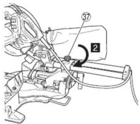
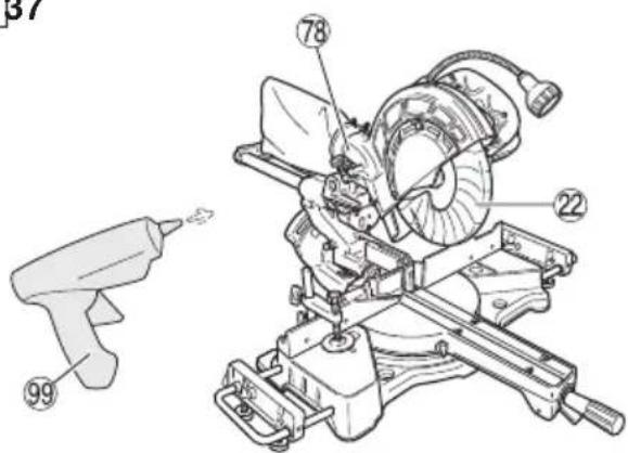
- Make sure to securely hold the tool during operation. Failure to do so can result in accidents or injuries. (Fig. 37)
SYMBOLS
WARNING
The following show symbols used for the machine. Be sure that you understand their meaning before use.
| C8FSHE / C8FSE: Slide Compound Miter Saw | |
| To reduce the risk of injury, user must read instruction manual. | |
| Always wear eye protection. | |
| Always wear hearing protection. | |
| Only for EU countriesDo not dispose of electric tools together with household waste material!In observance of European Directive 2012/19/EU on waste electrical and electronic equipment and its implementation in accordance with national law, electric tools that have reached the end of their life must be collected separately and returned to an environmentally compatible recycling facility. |
SPECIFICATIONS
| Max. Cutting Capacity Height × Width | 0° | 65 mm × 312 mm**75 mm × 262 mm with aux. board (30 mm) | ||
| Miter 45° | 65 mm × 220 mm**75 mm × 185 mm with aux. board (20 mm) | |||
| Bevel | Left 45° | 45 mm × 312 mm**50 mm × 252 mm with aux. board (30 mm) | ||
| Right 5° | 60 mm × 312 mm**70 mm × 252 mm with aux. board (30 mm) | |||
| Compound | Bevel (Left) 45° + Miter 45° | 45 mm × 220 mm**50 mm × 170 mm with aux. board (30 mm) | ||
| Bevel (Right) 5° + Miter 45° | 60 mm × 220 mm**70 mm × 170 mm with aux. board (30 mm) | |||
| Saw Blade Dimensions (oD × iD × Thickness) 216 mm × 30 mm × 2 mm | ||||
| Maximum kerf 2.7 mm | ||||
| Miter Cutting Angle Right 0° – 57°, Left 0° – 45° | ||||
| Bevel Cutting Angle Right 0° – 5°, Left 0° – 48° | ||||
| Compound Cutting Angle | Bevel (Left) 0° – 45° | Miter (Right and Left) 0° – 45° | ||
| Bevel (Right) 0° – 5° | ||||
| Voltage (by areas)* | (110 V, 230 V) ~ | |||
| Power Input* 1050 W | ||||
| No-Load Speed C8FSHE • C8FSE: 5500 min | -1 | |||
| Machine Dimensions (Width × Depth × Height) 555 mm × 790 mm × 485 mm | ||||
| Weight (Net)** 16.7 kg (C8FSHE) / 16.4 kg (C8FSE) | ||||
| Laser Marker(Only Model C8FSHE) | Maximum output Po<3 mW | Class II Laser Product | ||
| (lambda) 654 nm | ||||
| Laser medium Laser Diode | ||||
* Be sure to check the nameplate on product as it is subject to change by areas.
When cutting the workpiece which has the dimension of “**” there might be some possibility of the lower end of the circular saw to touch with the workpiece, even if the motor head is located at the lower limit position. Pay attention when cutting the workpiece. For further details, refer to “PRACTICAL APPLICATIONS”. Mount the auxiliary board on the fence surface (Refer () the thickness of auxiliary board). Refer to “10. Cutting large workpieces” (Fig. 22, 23).
1. Minimum size of the workpiece.
All workpieces that can be clamped left or right from the saw blade with the supplied vise assembly.
Model C8FSHE • C8FSE: 245 × 90mm (length × width)
2. Maximum cutting depth.
Model C8FSHE • C8FSE: 65mm (Miter 0° × Bevel 0°)
** According to EPTA-Procedure 01/2014
STANDARD ACCESSORIES
○ 216 mm TCT Saw blade (mounted on tool) .....1
○ Dust bag ....1
○ 10 mm Box wrench ....1
○ Vise Assembly ....1
○ Holder 1
○ Side Handle ....1
○ Sub Fence (mounted on tool) ....1
○ Sub table ass'y ....2
Standard accessories are subject to change without notice.
APPLICATION
Cutting various types of aluminium sash and wood.
PRIOR TO OPERATION
CAUTION
Make all necessary adjustments before inserting the plug in the power source.
1. Power source
Ensure that the power source to be utilized conforms to the power requirements specified on the product nameplate.
Do not use with direct current, or transformers such as boosters. Doing so may result in damage or accidents.
2. Power switch
Ensure that the power switch is in the OFF position. If the plug is connected to a receptacle while the trigger switch is in the ON position, the power tool will start operating immediately, inviting serious accident.
3. Extention cord
When the work area is removed from the power source, use an extension cord of sufficient thickness and rated capacity. The extension cord should be kept as short as practicable.
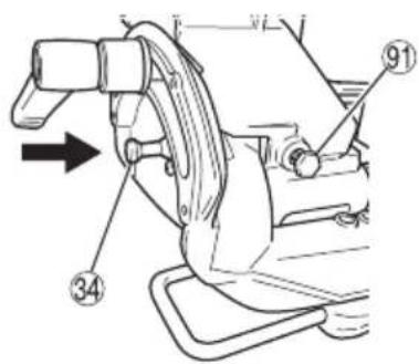
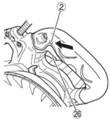
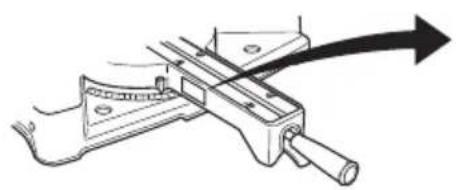
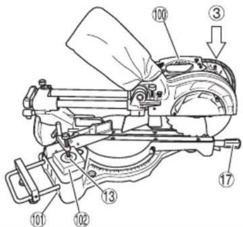
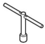
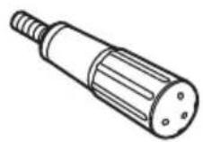
4. Releasing the locking pin (Fig. 3)
When the power tool is prepared for shipping, its main parts are secured by a locking pin.
Move the handle slightly so that the locking pin can be disengaged.
During transport, lock the locking pin into the gear case.
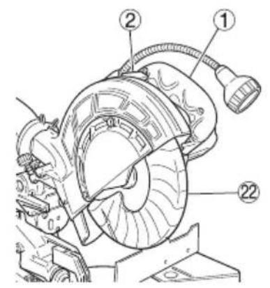
5. Attach the dust bag to the main unit (Fig. 1)
6. Installation (Fig. 4)
Ensure that the machine is always fixed to bench.
Attach the power tool to a level, horizontal work bench. Select 8 mm diameter bolts suitable in length for the thickness of the work bench.
Bolt length should be at least 25 mm plus the thickness of the work bench.
For example, use 8 mm × 65 mm bolts for a 25 mm thick work bench.
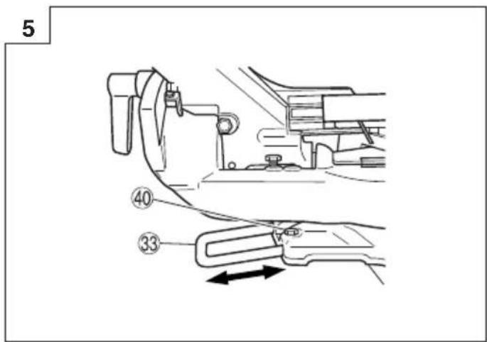
7. Base holder adjustment (Fig. 5)
Loosen the 6 mm bolt with the supplied 10 mm box wrench. Adjust the base holder until its bottom surface contacts the bench or the floor surface.
After adjustment, firmly tighten the 6 mm bolt.
8. Check to see that the lower guard operates smoothly
CAUTION
- This slide compound miter saw is equipped with a saw head lock as safety device.
☐ To lower the saw head to cut, the lock must be released by pressing the lock lever with your thumb.
(1) When you push down the handle while pushing the lock lever, check that the lower guard revolves smoothly (Fig. 6).
(2) Next, check that the lower guard returns to the original position when the handle is raised.
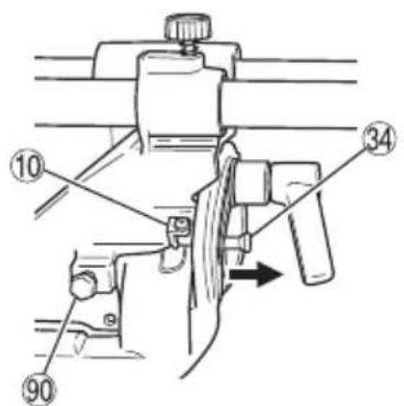
9. Oblique angle
Before the power tool is shipped from the factory, it is adjusted for 0^ , right angle, left 45^ bevel cutting angle with the 8 mm bolt (A) and 8 mm bolt (B).
When changing the adjustment, change the height of the 8 mm bolt (A) or 8 mm bolt (B) by turning them.
When changing the bevel angle to the left 45^ and over, pull the set pin on the direction shown in Fig. 7-a and incline the motor head to the left.
When changing the bevel angle to the right, pull the set pin on the direction shown in Fig. 7-a and incline the motor head to the right.
When adjusting the motor head to 0^ , always return the set pin to its initial position as shown in Fig. 7-b.
10. Checking the saw blade lower limit position
Check that the saw blade can be lowered 10 mm to 11 mm below the table insert.
When you replace a saw blade with a new one, adjust the lower limit position so that the saw blade will not cut the turntable or complete cutting cannot be done.
To adjust the lower limit position of the saw blade, follow the procedure (1) indicated below. (Fig. 8)
Furthermore, when changing the position of a 8 mm depth adjustment bolt that serves as a lower limit position stopper of the saw blade.
(1) Turn the 8 mm depth adjustment bolt, change the height where the bolt head and the hinge contacts, and adjust the lower limit position of the saw blade.
NOTE
Confirm that the saw blade is adjusted so that it will not cut into the turntable.
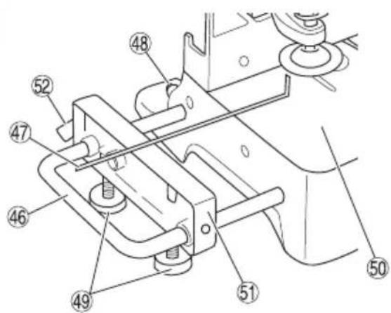
Using an item such as a steel square, match the upper surfaces of the base surface and sub table. Adjust the vertical level of the sub table by turning the 8 mm height adjustment bolt. After the adjustment, secure the holder with the 6 mm bolt on the rear of the base, and secure the 6 mm wing bolt of the sub table.
PRIOR TO CUTTING
1. Cutting a groove on the guard
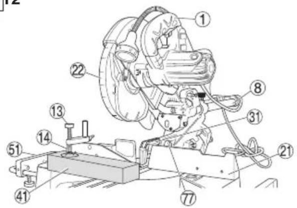
Holder (A) has a guard (see Fig. 11) into which a groove must be cut when using the tool for the first time. Loosen the 6 mm knob bolt to retract the guard slightly.
After placing a suitable wooden piece to sit on the fence and the table surfaces, fix it with the vise. Slide the motor head backwards to the end. Then tighten the slide securing knob. After the switch has been turned on and the saw blade has reached maximum speed, slowly lower the handle to cut a groove on the guard. (See Fig. 21)
CAUTION
Do not cut the groove too quickly; otherwise the guard might become damaged.
Do not use slide cutting for grooving tasks.
PRACTICAL APPLICATIONS
WARNING
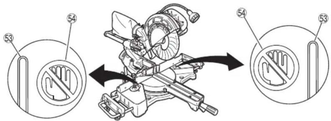
To avoid personal injury, never remove or place a workpiece on the table while the tool is being operated.
Never place your limbs inside of the line next to warning sign while the tool is being operated (see Fig. 10). This may cause hazardous conditions.
CAUTION
- It is dangerous to remove or install the workpiece while the saw blade is turning.
○ When sawing, clean off the shavings from the turntable.
☐ If the shavings accumulate too much, the saw blade from the cutting material will be exposed. Never subject your hand or anything else to go near the exposed blade.
1. Switch operation
The tool will not start unless the Lock-off button is pressed while the switch is pulled back.
The Lock-off button can be engaged by pressing it from the left.
After the switch is on, the saw blade will continue to operate as long as you pull on the switch trigger, even if you release the Lock-off button.
When the switch is released, the Lock-off button automatically disengages to prevent inadvertent motor startup.
WARNING
Never lock the Lock-off button in depressed position.
Pulling back the switch would then cause the tool to suddenly start operating, which could result in injury.
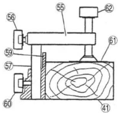
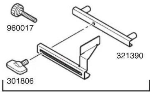
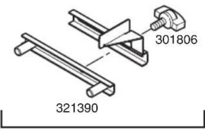
2. Using the Vise Assembly (Standard accessory) (Fig. 13)
(1) The vise assembly can be mounted on either the left fence {Fence (B)} or the right fence {Fence (A)} by loosening the 6 mm wing bolt (A).
(2) The screw holder can be raised or lowered according to the height of the workpiece by loosening the 6 mm wing bolt (B). After the adjustment, fi rmly tighten the 6 mm wing bolt (B) and fi x the screw holder.
(3) Turn the upper knob and securely fix the workpiece in position.
WARNING
Always firmly clamp or vise to secure the workpiece the fence; otherwise the workpiece might be thrust from the table and cause bodily harm.
CAUTION
Always confirm that the motor head does not contact the vise assembly when it is lowered for cutting. If there is any danger that it may do so, loosen the 6 mm wing bolt and move the vise assembly to a position where it will not contact the saw blade.
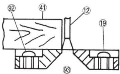
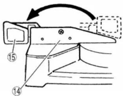
3. Positioning the table insert (Fig. 14)
Table inserts are installed on the turntable. When shipping the tool from the factory, the table inserts are so fi xed that the saw blade does not contact them. The burr of the bottom surface of the workpiece is remarkably reduced, if the table insert is fi xed so that the gap between the side surface of the table insert and the saw blade will be minimum. Before using the tool, eliminate this gap in accordance with the following procedure.
(1) Right angle cutting
Loosen the three 6 mm machine screws, then secure the left side table insert and temporarily tighten the 6 mm machine screws of both ends. Then fi x a workpiece (about 200 mm wide) with the vise assembly and cut it off . After aligning the cutting surface with the edge of the table insert, securely tighten the 6 mm machine screws of both ends. Remove the workpiece and securely tighten the 6 mm center machine screw. Adjust the right hand table insert in the same way.
(2) Left and right bevel angle cutting
Adjust the table insert in the manner same procedure for right angle cutting.
CAUTION
After adjusting the table insert for right angle cutting, the table insert will be cut to some extent if it is used for bevel angle cutting.
When bevel cutting operation is required, adjust the table insert for bevel angle cutting.
4. Confirmation for use of sub fence (Fig. 15)
This slide compound miter saw is equipped with a sub fence. In the case of direct angle cutting and right bevel angle cutting, use the sub fence. Then, you can do Left bevel angle cutting, Right bevel angle cutting and Direct angle cutting and realize stable cutting of the material with a wide back face.
WARNING
In the case of left bevel cutting, turn the sub fence counterclockwise (Fig. 15). Unless it is turned counterclockwise, the main body or saw blade may contact the sub fence, resulting in an injury.
5. Using an ink line (Adjusting the guard)
(1) Right angle cutting
Loosen the 6 mm knob bolt and contact the tip of the guard with the workpiece.
Aligning the ink line on the workpiece with the groove of the guard, the workpiece is cut on the ink line.
(2) Miter cutting and compound cutting (Miter cutting + bevel cutting) Upon lowering the motor section, the lower guard is raised and the saw blade appears.
Align the ink line with the saw blade.
CAUTION
In some arrangements when the turntable is rotated, the guard projects from the fence surface. Loosen the 6 mm knob bolt and push the guard to the retracted position. Never lift the lower guard while the saw blade is rotating. When cutting at an angle of 45^ to the right or more, please slide the guard to the rear.
The guard and sub-fence will not only make contact and adversely affect cutting accuracy, this could also result in damage to the guard.
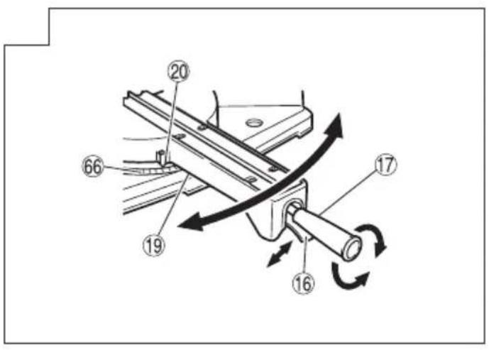
6. Install the side handle (Fig. 1)
olnstall the side handle that came enclosed with this unit.
7. Position adjustment of laser line (Only Model C8FSHE)
Ink lining can be easily made on this tool to the laser marker. A switch lights up the laser marker (Fig. 16).
Depending upon your cutting choice, the laser line can be aligned with the left side of the cutting width (saw blade) or the ink line on the right side.
The laser line is adjusted to the width of the saw blade at the time of factory shipment. Adjust the positions of the saw blade and the laser line taking the following steps to suit the use of your choice.
(1) Light up the laser marker and make a groove of about 5 mm deep on the workpiece that is about 20 mm in height and 150 mm in width. Hold the grooved workpiece by vise as it is and do not move it. For grooving work, refer to "19. Groove cutting procedures".
(2) Then, turn the adjuster and shift the laser line. (If you turn the adjuster clockwise, the laser line will shift to the right and if you turn it counterclockwise, the laser line will shift to the left.) When you work with the ink line aligned with the left side of the saw blade, align the laser line with the left end of the groove (Fig. 17). When you align it with the right side of the saw blade, align the laser line with the right side of the groove.
(3) After adjusting the position of the laser line, draw a right-angle ink line on the workpiece and align the ink line with the laser line. When aligning the ink line, slide the workpiece little by little and secure it by vise at a position where the laser line overlaps with the ink line. Work on the grooving again and check the position of the laser line. If you wish to change the laser line's position, make adjustments again following the steps from (1) to (3).
WARNING
○ Make sure before plugging the power plug into the receptacle that the main body and the laser marker are turned off.
Exercise utmost caution in handling a switch trigger for the position adjustment of the laser line, as the power plug is plugged into the receptacle during operation.
If the switch trigger is pulled inadvertently, the saw blade can rotate and result in unexpected accidents.
- Do not remove the laser marker to be used for other purposes.
English
CAUTION (Fig. 18)
○ Laser radiation - Do not stare into beam.
○ Laser radiation on work table. Do not stare into beam. If your eye is exposed directly to the laser beam, it can be hurt.
○ Do not dismantle it.
☐ Do not give strong impact to the laser marker (main body of tool); otherwise, the position of a laser line can go out of order, resulting in the damage of the laser marker as well as a shortened service life.
Keep the laser marker lit only during a cutting operation. Prolonged lighting of the laser marker can result in a shortened service life.
○ Use of controls or adjustments or performance of procedures other than those specified herein may result in hazardous radiation exposure.
NOTE
○ Perform cutting by overlapping the ink line with the laser line.
When the ink line and the laser line are overlapped, the strength and weakness of light will change, resulting in a stable cutting operation because you can easily discern the conformity of lines. This ensures the minimum cutting errors.
○ In outdoor or near-the-window operations, it may become difficult to observe the laser line due to the sunlight. Under such circumstances, move to a place that is not directly under the sunlight and engage in the operation.
☐ Check and make sure on a periodic basis if the position of the laser line is in order. As regards the checking method, draw a right-angle ink line on the workpiece with the height of about 20 mm and the width of 150 mm, and check that the laser line is in line with the ink line [The deviation between the ink line and the laser line should be less than the ink line width (0.5 mm)]. (Fig. 19)
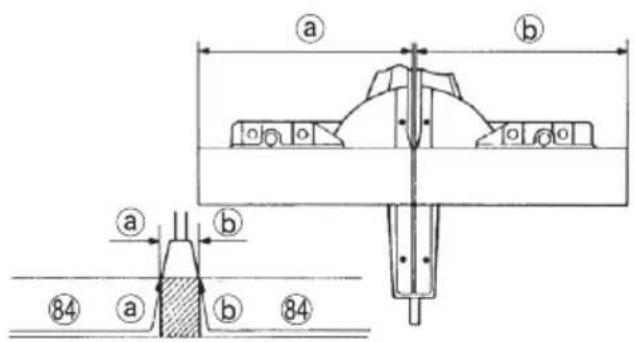
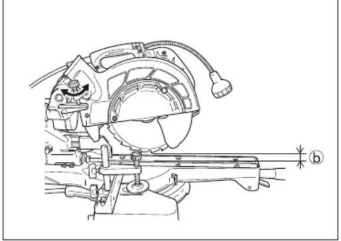
8. Cutting operation
(1) As shown in Fig. 20 the width of the saw blade is the width of the cut. Therefore, slide the workpiece to the right (viewed from the operator's position) when length b is desired, or to the left when length is desired.
If a laser marker is used, align the laser line with the left side of the saw blade, and then align the ink line with the laser line.
(2) After turning on the switch and checking that the saw blade is rotating at maximum speed, slowly push down the handle while holding down the lock lever and bring the saw blade in the vicinity of the material to be cut.
(3) Once the saw blade contacts the workpiece, push the handle down gradually to cut into the workpiece.
(4) After cutting the workpiece to the desired depth, turn the power tool OFF and let the saw blade stop completely before raising the handle from the workpiece to return it to the full retract position.
CAUTION
○ For maximum dimensions for cutting, refer to "SPECIFICATIONS" table.
○ Increased pressure on the handle will not increase the cutting speed. On the contrary, too much pressure may result in overload of the motor and/or decreased cutting efficiency.
○ Confirm that the trigger switch is turned OFF and the power plug has been removed from the receptacle whenever the tool is not in use.
○ Always turn the power off and let the saw blade stop completely before raising the handle from the workpiece. If the handle is raised while the saw blade is still rotating, the cut-off piece may become jammed against the saw blade causing fragments to scatter about dangerously.
○ Every time one cutting of deep-cutting operation is finished, turn the switch off, and check that the saw blade has stopped. Then raise the handle, and return it to the full retract position.
○ Be absolutely sure to remove the cut material from the top of the turntable, and then proceed to the next step.
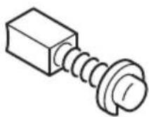
9. Cutting narrow workpieces (Press cutting) (Fig. 21)
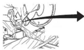
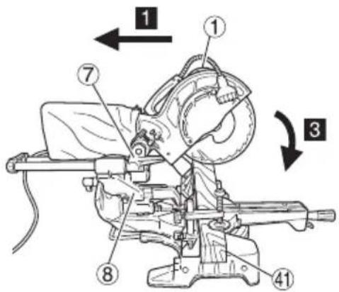
Slide the hinge down to holder (A), then tighten the slide securing knob (Fig. 2). Lower the handle to cut the workpiece. Using the power tool this way will permit cutting of workpieces of up to 65 mm square.
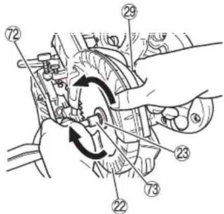
10. Cutting large workpieces (Fig. 22, 23)
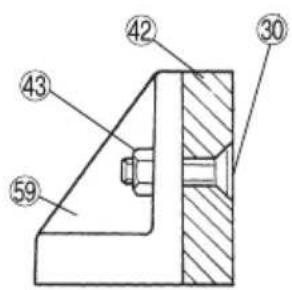
There may be case when a complete cutting cannot be done depending on the height of workpiece. In this case, mount an auxiliary board with the 6 mm fl at head screws and the 6 mm nuts using the 7 mm holes on the fence surface (two holes on each side). (Fig. 22)
Refer to "SPECIFICATIONS" for the thickness of the auxiliary board.
NOTE
When cutting a workpiece exceeding 65 mm in height in right-angle cutting or 60 mm in left bevel angle cutting or 45 mm in right bevel angle cutting, adjust the lower limit position so that the base of the motor head will not come in contact with the workpiece.
To adjust the lower limit position of the saw blade, follow the procedure (1) shown in Fig. 23.
(1) Lower the motor head, and turn the 6 mm depth adjustment bolt and make adjustments so that there can be a clearance of 2 mm to 3 mm between the lower limit position of the motor head and the top of the workpiece at the saw blade's lower limit position where the head of the 6 mm depth adjustment bolt contacts the hinge.
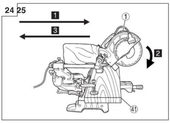
11. Cutting wide workpieces (Slide cutting) (Fig. 24)
Loosen the slide securing knob (Fig. 2), grip the handle and slide the saw blade forward. Then press down on the handle and slide the saw blade back to cut the workpiece. This facilitates cutting of workpieces of up to 312 mm in width.
WARNING
Never put your hand on the side handle during the cutting operation because the saw blade comes close to the side handle when the motor head is lowered.
12. Miter cutting procedures
(1) Loosen the side handle and pull up the lever for angle stoppers. Then, adjust the turntable until the indicator aligns with desired setting on the miter scale (Fig. 25).
(2) Re-tighten the side handle to secure the turntable in the desired position.
(3) The miter scale indicates both the cutting angle on the angle scale and the gradient on the grade scale.
(4) The gradient, which is the ratio of the height to the base of the triangular section to be removed, may be used for setting the miter scale instead of the cutting angle, if desired.
Therefore, to cut a workpiece at a grade of 2/10, set the indicator to position.
NOTE
○ Positive stops are provided at the right and left of the 0^ center setting, at 15^ , 22.5^ , 31.6^ and 45^ settings.
Check that the miter scale and the tip of the indicator are properly aligned.
Operation of the saw with the miter scale and indicator out of alignment, or with the side handle not properly tightened, will result in poor cutting precision.
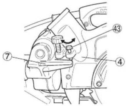
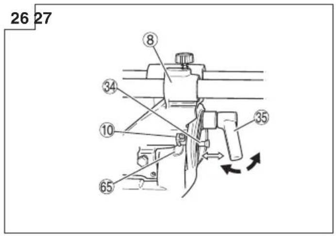
13. Bevel cutting procedures (Fig. 26)
(1) Loosen the clamp lever and bevel the saw blade to the left or to the right. When tilting the motor head to the right pull the set pin towards the rear.
NOTE
Loosen the clamp lever, tilt the main unit to the left and then pull the set pin to enable 48-degree cuts.
Loosen the clamp lever and slant to the left a little at a time while pushing the set pin into the main unit. At this time, the set pin will enter one step and fit into the 30^ left slant and 33.9^ left slant setting slots.
With the set pin in the slot as described above, setting to the 30^ left slant position is possible by pushing to the right side.
Also, with the set pin in the slot as described above, setting to the 33.9^ left slant position is possible by pushing to the left side.
(2) Adjust the bevel angle to the desired setting while watching the bevel angle scale and indicator, then secure the clamp lever.
WARNING
When the workpiece is secured on the left or right side of the blade, the short cut-off portion will come to rest on the right or left side of the saw blade. Always turn the power off and let the saw blade stop completely before raising the handle from the workpiece.
If the handle is raised while the saw blade is still rotating, the cut-off piece may become jammed against the saw blade causing fragments to scatter about dangerously.
When stopping the bevel cutting operation halfway, start cutting after pulling back the motor head to the initial position.
Starting from halfway, without pulling back, causes the lower guard to be caught in the cutting groove of the workpiece and to contact the saw blade.
14. Compound cutting procedures
Compound cutting can be performed by following the instructions in 13 and 14 above. Formaximum dimensions for compound cutting, refer to "SPECIFICATIONS" table.
CAUTION
Always secure the workpiece with the right or left hand and cut it by sliding the round portion of the saw backwards with the left hand.
It is very dangerous to rotate the turntable to the left during compound cutting because the saw blade may come into contact with the hand that is securing the workpiece.
In case of compound cutting (angle + bevel) by left bevel, turn the sub-fence (optional accessory) counterclockwise, and engage in the cutting operation.
15. Cutting long materials
When cutting long materials, use an auxiliary platform which is the same height as the holder and base of the special auxiliary equipment.
Capacity: wooden material (W × H × L)
300 mm × 45 mm × 1050 mm, or
180 mm × 25 mm × 1600 mm
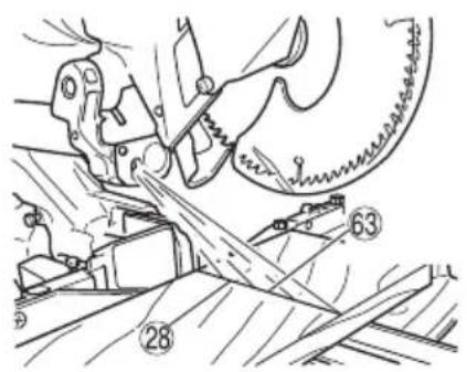
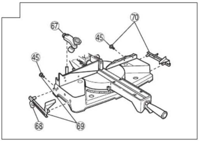
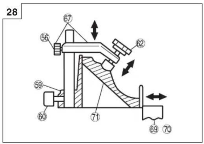
16. Confir rmation for use Crown molding vise, Crown molding Stopper (L) and (R) (Optional accessory)
(1) Crown molding Stopper (L) and (R) (optional accessories) allow easier cuts of crown molding without tilting the saw blade. Install them in the base both-sides side to be shown in Fig. 27. After inserting tighten the 6 mm knob bolts to secure the Crown molding Stoppers.
(2) The crown molding vise (B) (Optional accessory) can be mounted on either the left fence (Fence (B)) or the right fence (Fence (A)). It can unite with the slope of the crown molding and vice can be pressed down.
Then turn the upper knob, as necessary, to securely attach the crown molding in position. To raise or lower the vise assembly, first loosen the 6 mm knob bolt.
After adjusting the height, firmly tighten the 6 mm wing bolt; then turn the upper knob, as necessary, to securely attach the crown molding in position (Fig. 28).
Position crown molding with its WALL CONTACT EDGE against the guide fence and its CEILING CONTACT EDGE against the Crown molding Stoppers as shown in Fig. 28. Adjust the Crown molding Stoppers according to the size of the crown molding.
Tighten the 6 mm wing bolt to secure the Crown molding Stoppers.
WARNING
Always firmly clamp or vise to secure the crown molding to the fence; otherwise the crown molding might be thrust from the table and cause bodily harm.
Do not bevel cutting. The main body or saw blade may contact the sub fence, resulting in an injury.
CAUTION
Always confirm that the motor head does not contact the crown molding vise ass'y when it is lowered for cutting. If there is any danger that it may do so, loosen the 6 mm knob bolt and move the crown molding vise ass'y to a position where it will not contact the saw blade.
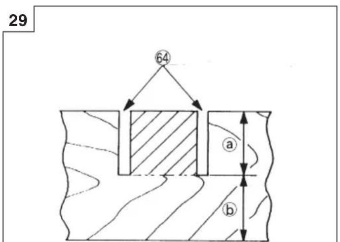
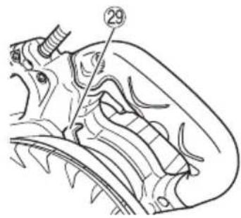
17. Groove cutting procedures
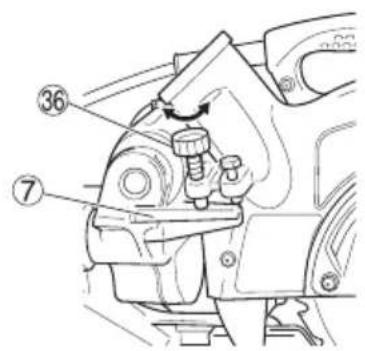
Grooves in the workpiece can be cut by adjusting the 6 mm depth adjustment bolt (Fig. 29).
(1) Lower the motor head, and turn the 6 mm depth adjustment bolt by hand. (Where the head of the 6 mm depth adjustment bolt contacts the hinge.)
(2) Adjust to the desired cutting depth by setting the distance between the saw blade and the surface of the base. (Fig. 29)
NOTE
When cutting a single groove at either end of the workpiece, remove the unneeded portion with a chisel.
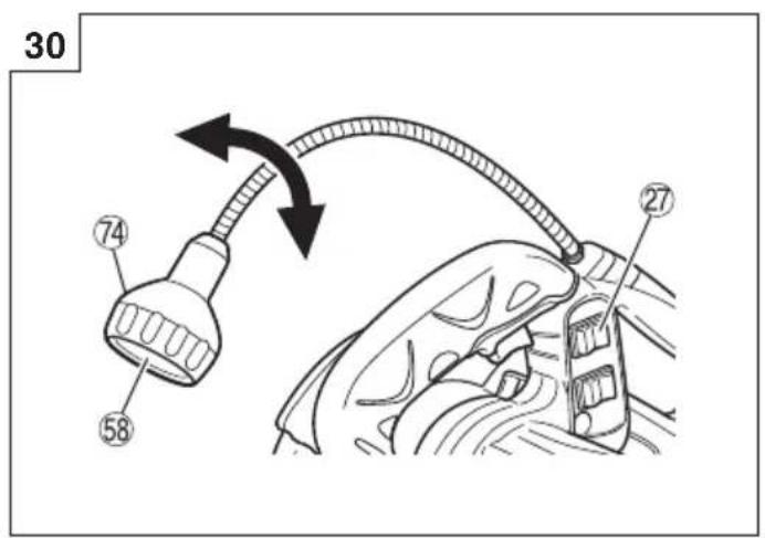
18. Using the Light (Only Model C8FSHE)
WARNING
☐ Check to ascertain that the main unit and light are off before plugging the cord into the power socket.
☐ The light lens reaches high temperatures during and immediately after use and should not be touched under any circumstances.
Failure to observe this may result in burns.
CAUTION
○ Do not subject the light to strong impact.
Failure to observe this may result in damage to the light or a reduced life span.
○ Only switch the light on when cutting.
○ Do not shine the light continuously into the eyes.
Failure to observe this may result in damage to the eyes.
○ Wipe all dirt that adheres to the light lens with a soft cloth gently so that the light is not scratched or damaged.
Scratches on the light lens may result in less luminance.
○ The light switch is fitted with an anti-dust cover. Make sure that the switch cover is not scratched or otherwise damaged.
There are cases in which shavings may enter the switch and prevent the light from functioning.
(1) Insert the plug on the main unit into a power socket.
(2) Set the light switch into the upper position (ON) to light it, and into the lower position (OFF) to switch it off. (See Fig. 30)
(3) Move the light fitting to the right and left to adjust the lighting position.
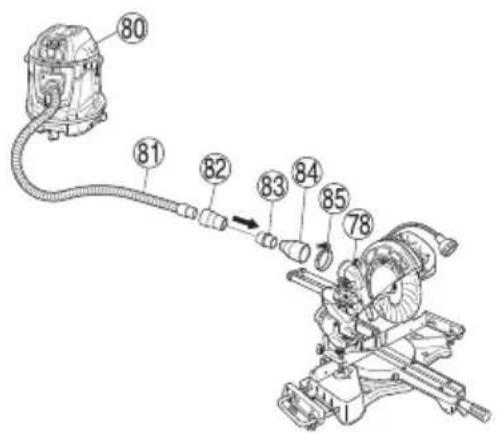
19. Using the dust bag (Standard accessory) (Fig. 31)
(1) Connect the dust bag with the duct of power tool.
(2) When the dust bag has become full of sawdust, dust will be blown out of the dust bag when the saw blade rotates. Check the dust bag periodically and empty it before it becomes full.
(3) During bevel and compound cutting, attach the dust bag at the right angle to the base surface.
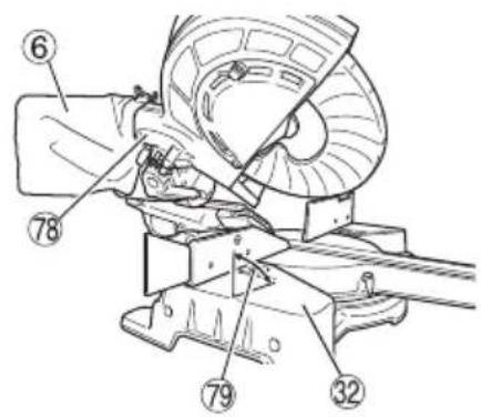
20. Connecting the dust extractor (Sold separately) (Fig. 32)
Do not inhale the harmful dusts generated in cutting operation.
The dust can endanger the health of yourself and bystanders.
Use of dust extractor can reduce dust related hazards.
By connecting with dust extractor through adapter, joint and dust collection adapter, most of dust can be collected.
Connect the dust extractor with adapter.
(1) Connect in order of hose (id 38 mm × 3 m long) and adapter (Dust extractor's Standard accessory) joint (Optional accessory) and dust collection adapter (Optional accessory) with the duct of power tool.
Connection is done by pressing in the direction of the arrow. (Fig. 32)
The dust collection adapter (Optional accessory) is fixed to the duct by a hose band. (Optional accessory)
MOUNTING AND DISMOUNTING SAW BLADE
WARNING
To prevent an accident or personal injury, always turn off the trigger switch and disconnect the power plug from the receptacle before removing or installing a blade.
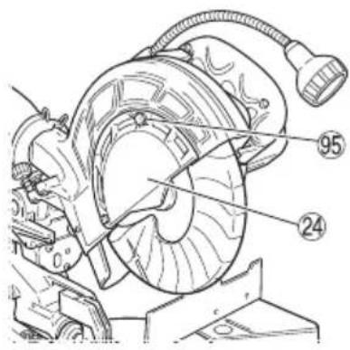
1. Mounting the saw blade (Fig. 33)
(1) Use the accessory 10 mm box wrench to loosen the 6 mm bolt fastening the spindle cover and then rotate the spindle cover.
(2) Press in spindle lock and loosen bolt with 10 mm box wrench.
Since the bolt is left-hand threaded, loosen by turning it to the right.
NOTE
If the spindle lock cannot be easily pressed in to lock the spindle, turn the bolt with 10 mm box wrench while applying pressure on the spindle lock.
The saw blade spindle is locked when the spindle lock is pressed inward.
(3) Remove the bolt and washer (D).
(4) Lift the lower guard and mount the saw blade.
WARNING
When mounting the saw blade, confirm that the rotation indicator mark on the saw blade and the rotation direction of the gear case are properly matched.
(5) Thoroughly clean washer (D) and the bolt, and install them onto the saw blade spindle.
(6) Press in the spindle lock and tighten the bolt by turning it to the left by 10 mm box wrench.
(7) Rotate the spindle cover unit hook in spindle cover is in the original position. Then tighten the 6 mm bolt.
CAUTION
○ Confirm that the spindle lock has returned to the retract position after installing or removing the saw blade.
○ Tighten the bolt so it does not come loose during operation.
○ Confirm that the bolt has been properly tightened before the power tool is started.
○ Confirm that the lower guard has closed position.
2. Dismounting the saw blade
Dismount the saw blade by reversing the mounting procedures described in paragraph 1 above.
The saw blade can easily be removed after lifting the lower guard.
CAUTION
Never attempt to install saw blades except
216 mm in diameter.
TRANSPORTATION OF THE MAIN BODY
The vice assembly could be dropped during transportation. Either remove the assembly or slip a piece of wood between the vice to firmly secure it.
Drop the head and insert the locking pin (see page 20 "Releasing the locking pin").
Turn and loosen the side handle, turn the turntable as far right as it will go, and secure the turntable by turning the handle to the fixed position. This will make the main body even more compact.
When transporting the main body, carry it in your arms, holding the grip located on the base with both hands or carry handle.
MAINTENANCE AND INSPECTION
WARNING
To avoid an accident or personal injury, always confirm the trigger switch is turned OFF and that the power plug has been disconnected from the receptacle before performing any maintenance or inspection of this tool.
Report to qualified person as soon as possible, if you discover the fault of machine including guards or blade saw.
1. Inspecting the saw blade
Always replace the saw blade immediately upon the first sign of deterioration or damage.
A damaged saw blade can cause personal injury and a worn saw blade can cause ineffective operation and possible overload to the motor.
CAUTION
Never use a dull saw blade. When a saw blade is dull, its resistance to the hand pressure applied by the tool handle tends to increase, making it unsafe to operate the power tool.
2. Inspecting the mounting screws
Regularly inspect all mounting screws and ensure that they are properly tightened. Should any of the screws be loose, re-tighten them immediately. Failure to do so could result in serious hazard.
3. Inspecting the carbon brushes (Fig. 35)
The motor employs carbon brushes which are consumable parts. Since an excessively worn carbon brush can result in motor trouble, replace the carbon brushes with new ones having the same carbon brush No. shown in the figure when it becomes worn to or near the “wear limit”. In addition, always keep carbon brushes clean and ensure that they slide freely within the brush holders.
4. Replacing a carbon brushes (Fig. 35)
Disassemble the brush cap with a slotted-head screwdriver. The carbon brushes can then be easily removed.
5. Maintenance of the motor
The motor unit winding is the very “heart” of the power tool. Exercise due care to ensure the winding does not become damaged and/or wet with oil or water.
6. Replacing supply cord
If the supply cord of Tool is damaged, the Tool must be returned to HiKOKI Authorized Service Center for the cord to be replaced.
7. Inspecting the lower guard for proper operation
Before each use of the tool, test the lower guard (Fig. 6)
to assure that it is in good condition and that it moves smoothly.
Never use the tool unless the lower guard operates properly and it is in good mechanical condition.
8. Storage
After operation of the tool has been completed, check that the following has been performed:
(1) Trigger switch is in OFF position,
(2) Power plug has been removed from the receptacle, When the tool is not in use, keep it stored in a dry place out of the reach of children.
9. Lubrication
Lubricate the following sliding surfaces once a month to keep the power tool in good operating condition for a long time.
Use of machine oil is recommended.
Oil supply points:
* Rotary portion of hinge
* Rotary portion of holder (A)
* Rotary portion of vise assembly
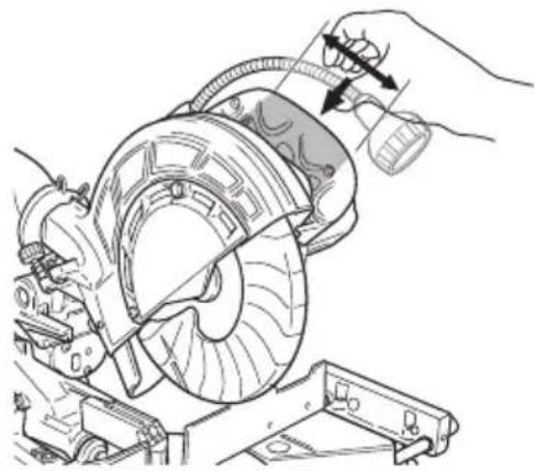
10. Cleaning
Periodically remove chips and other waste material from the surface of the power tool with a damp, soapy cloth. To avoid a malfunction of the motor, protect it from contact with oil or water.
Clean the machine, duct, lower guard, by blowing with dry air from an air gun or other tool. (Fig. 36)
(Only Model C8FSHE)
If the laser line becomes invisible due to chips and the like adhered onto the window of the laser marker's light-emitting section, wipe and clean the window with a dry cloth or a soft cloth moistened with soapy water, etc.
SELECTING ACCESSORIES
The accessories of this machine are listed on page 98.
CAUTION
Repair, modification and inspection of HiKOKI Power Tools must be carried out by a HiKOKI Authorized Service Center.
Especially laser or LED device should be maintained by the authorized agent by laser or LED manufacturer.
Always assign the repair of laser or LED device to HiKOKI Authorized Service Center.
In the operation and maintenance of power tools, the safety regulations and standards prescribed in each country must be observed.
GUARANTEE
We guarantee HiKOKI Power Tools in accordance with statutory/country specific regulation. This guarantee does not cover defects or damage due to misuse, abuse, or normal wear and tear. In case of complaint, please send the Power Tool, undismantled, with the GUARANTEE CERTIFICATE found at the end of this Handling instruction, to a HiKOKI Authorized Service Center.
NOTE
Due to HiKOKI's continuing program of research and development the specifications herein are subject to change without prior notice.
Information concerning airborne noise
The measured values were determined according to EN62841 and declared in accordance with ISO 4871.
Measured A-weighted sound power level: 105 dB (A). Measured A-weighted sound pressure level: 96 dB (A). Uncertainty K: 3 dB (A).
Wear hearing protection.
The declared noise emission value has been measured in accordance with a standard test method and may be used for comparing one tool with another;
It may also be used in a preliminary assessment of exposure. WARNING
☐ The noise emissions during actual use of the power tool can differ from the declared values depending on the ways in which the tool is used especially what kind of workpiece is processed.
- Identify safety measures to protect the operator that are based on an estimation of exposure in the actual conditions of use (taking account of all parts of the operating cycle such as the times when the tool is switched off and when it is running idle in addition to the trigger time).
Information for power supply system to be used with electric tools provided with rated voltage 230 V\~
Switching operations of electric apparatus cause voltage fluctuations.
The operation of this electric tool under unfavorable mains conditions can have adverse effects to the operation of other electric apparatus.
With a mains impedance equal or less than 0.29 Ohms there will probably be no negative effects.
Usually, the maximum permissible mains impedance will not be exceeded when the branch to the power outlet is fed from a junction box with a service capacity of 25 ampere or higher.
In case of power failure, or when the power plug is pulled out, immediately return the switch to OFF position. This prevents an uncontrolled restart.
ALLGEMEINE
APPLICATIONS PRATIQUES
AVERTISSEMENT
TRANSPORT DU CORPS PRINCIPAL
(3) Move the light fitting to the right and left to adjust the lighting position.
300 mm × 45 mm × 1050 mm of
180 mm × 25 mm × 1600 mm
natural_image
Line drawing of a laboratory flask with a stopper (no text or symbols)322955
940543
natural_image
Simple line drawing of a U-shaped pipe or clamp (no text or symbols)998844
322283 230V: 999001
110V: 999021
321374
321373 329464
| English Nederlands | |
| GUARANTEE CERTIFICATE1 Model No.2 Serial No.3 Date of Purchase4 Customer Name and Address5 Dealer Name and Address(Please stamp dealer name and address) | GARANTIEBEWIJS1 Modelnummer2 Serienummer3 Datum van aankoop4 Naam en adres van de gebruiker5 Naam en adres van de handelaar(Stempel a.u.b. naam en adres vande de handelaar) |
| Deutsch Español | |
| GARANTIESCHEIN1 Modell-Nr.2 Serien-Nr.3 Kaufdaturn4 Name und Anschrift des Kunden5 Name und Anschrift des Händlers(Bitte mit Namen und Anschrift des Handlers abstempeln) | CERTIFICADO DE GARANTÍA1 Número de modelo2 Número de serie3 Fecha de adquisición4 Nombre y dirección del cliente5 Nombre y dirección del distribudor(Se ruega poner el sello del distribudor con su nombre y dirección) |
| Français Português | |
| CERTIFICAT DE GARANTIE1 No. de modèle2 No de série3 Date d'achat4 Nom et adresse du client5 Nom et adresse du revendeur(Cachet portant le nom et l'adresse du revendeur) | CERTIFICADO DE GARANTIA1 Número do modelo2 Número do série3 Data de compra4 Nome e morada do cliente5 Nome e morada do distribuidor(Por favor, carímbe o nome e morada do distribuidor) |
| Italiano | |
| CERTIFICATO DI GARANZIA1 Modello2 N° di serie3 Data di acquisto4 Nome e indirizzo dell'acquirente5 Nome e indirizzo del rivenditore(Si prega di apporre il timbro con questi dati) |
HiKOKI
| 1 | |
| 2 | |
| 3 | |
| 4 | |
| 5 |
Siemensring 34, 47877 willich, Germany
Tel: +49 2154 49930
Fax: +49 2154 499350
URL: http://www.hikoki-powertools.de
Hikoki Power Tools Netherlands B.V.
Brabanthaven 11, 3433 PJ Nieuwegein, The Netherlands
Tel: +31 30 6084040
Fax: +31 30 6067266
URL: http://www.hikoki-powertools.nl
Hikoki Power Tools (U.K.) Ltd.
Precedent Drive, Rooksley, Milton Keynes, MK 13, 8PJ,
United Kingdom
Tel: +44 1908 660663
Fax: +44 1908 606642
URL: http://www.hikoki-powertools.uk
Hikoki Power Tools France S.A.S.
Hikoki Power Tools Belgium N.V./S.A.
Koningin Astridlaan 51, B-1780 Wemmel, Belgium
Tel: +32 2 460 1720
Fax: +32 2 460 2542
URL http://www.hikoki-powertools.be
Hikoki Power Tools Italia S.p.A
Via Piave 35, 36077, Altavilla Vicentina (VI), Italy
Tel: +39 0444 548111
Fax: +39 0444 548110
URL: http://www.hikoki-powertools.it
Hikoki Power Tools Ibérica, S.A.
C/ Puigbarral, 26-28, Pol. Ind. Can Petit, 08227 Terrassa
(Barcelona), Spain
Tel: +34 93 735 6722
Fax: +34 93 735 7442
URL: http://www.hikoki-powertools.es
natural_image
Line drawing of a quill pen with inkwell, no text or symbols present
natural_image
Line drawing of a quill pen with inkwell, no text or symbols present| English Nederlands | ||
| EC DECLARATION OF CONFORMITYWe declare under our sole responsibility that Slide Compound Miter Saw, identified by type and specific identification code *1), is in conformity with all relevant requirements of the directives *2) and standards *3). Technical fi le at *4) – See below.The European Standard Manager at the representative office in Europe is authorized to compile the technical fi le.The declaration is applicable to the product affi xed CE marking. | EC VERKLARING VAN CONFORMITEITWij verklaren onder onze eigen verantwoordelijkheid dat Afkortzaagmachine met telescopisch zaagarm, ge'identificeerd door het type en de specifieke identificatiecode*1), voldoet aan alle relevante bepalingen van de richtlijnen*2) en normen*3). Technische documentatie bij*4) – zie onder.De Europese Normen Manager bij de vertegenwoordiging in Europa is gemachtigd om het technisch dossier samen te stellen.Deze verklaring is van toepassing op producten voorzien van de CE-markeringen. | |
| Deutsch Español | ||
| EG-KONFORMITÄTSERKLÄRUNGWir erklären in alleiniger Verantwortung, dass die durch den Typ und den spezifischen Identifizierungscode *1) identifizierte Paneelsäge allen einschlägigen Bestimmungen der Richtlinien *2) und Normen *3) entspricht. Technische Unterlagen unter *4) – Siehe unten.Die Leitung der repräsentativen Behörde für europäische Normen und Richtlinien ist berechtigt, die technischen Unterlagen zusammenzustellen.Die Erklärung gilt für die an dem Produkt angebrachte CE-Kennzeichnung. | DECLARACIÓN DE CONFORMIDAD DE LA CEDeclaramos bajo nuestra única responsabilidad que la Ingletadora telescópica, identificada por tipo y por código de identificación específico *1), está en conformidad con todas las disposiciones correspondientes de las directivas *2) y de las normas *3). Documentación técnica en *4) – Ver a continuación.El Director de Normas Europeas en la oficina de representación en Europa está autorizado para elaborar el expediente técnico.La declaración se aplica al producto con marcas de la CE. | |
| Français Português | ||
| DECLARATION DE CONFORMITE CENous déclarons sous notre entière responsabilité que la scie radiale à coupe d'onglet, identifiée par le type et le code d'identification spécifique *1) est en conformité avec toutes les exigences applicables des directives *2) et des normes *3). Dossier technique en *4) - Voir ci-dessous.Le Gestionnaire des normes européennes du bureau de représentation en Europe est autorisé à constituer le dossier technique.Cette déclaration s'applique aux produits désignés CE. | DECLARAÇÃO DE CONFORMIDADE CEDeclaramos, sob nossa única e inteira responsabilidade, que Serra Telescópica, identificada por tipo e código de identificação específico *1), está em conformidade com todos os requerimentos relevantes das diretivas *2) e normas *3). Ficheiro técnico em *4)–Consulte abaixo.O Gestor de Normas Europeas no escritório de representação na Europa está autorizado a compilar o fi cheiro técnico.A declaração aplica-se aos produtos com marca CE. | |
| Italiano | ||
| DICHIARAZIONE DI CONFORMITÀ CEDichiariamo sotto la nostra esclusiva responsabilità che la troncatrice da legno a taglio assiale e radiale, identificata dal tipo e dal codice identificativo specifico *1), è conforme a tutti i requisiti delle direttive *2) e degli standard *3). Documentazione tecnica presso *4) – Vedere sotto.Il gestore delle norme europee presso l'ufficio di rappresentanza in Europa è autorizzato a compilare il fascicolo tecnico.La dichiarazione è applicabile ai prodotti cui sono applicati i marchi CE. | ||
| *1) C8FSEC357309SC8FSHEC357307S*2) 2006/42/EC, 2014/30/EU, 2011/65/EU*3) EN62841-1:2015EN62841-3-9:2020+A11:2020EN55014-1:2006+A1:2009+A2:2011EN55014-2:1997+A1:2001+A2:2008EN61000-3-2:2014EN61000-3-3:2013 | ||
*4) Representative offi ce in EuropeHikoki Power Tools Deutschland GmbHSiemensring 34, 47877 Willich, GermanyHead offi ce in JapanKoki Holdings Co., Ltd.Shinagawa Intercity Tower A, 15-1, Konan 2-chome, Minato-ku, Tokyo, Japan 28.2.2022Akihisa YahagiEuropean Standard Manager28.2.2022A. NakagawaCorporate Offi cer 28.2.2022Akihisa YahagiEuropean Standard Manager28.2.2022A. NakagawaCorporate Offi cer | ||