
Crystal FHCR 302 2G HE - Cooker FRANKE - Free user manual and instructions
Find the device manual for free Crystal FHCR 302 2G HE FRANKE in PDF.

| Product Type | Built-in gas hob |
| Brand | Franke |
| Model | Crystal FHCR 302 2G HE |
| Dimensions (W x D) | 310 x 510 mm |
| Gross / Net weight | 7.5 kg / 6.5 kg |
| Number of burners | 2 gas burners |
| Total installed power | 4.00 kW (gas) + 0.6 W (electric) |
| Electrical supply | 220-240 V ~ 50/60 Hz, 16 A |
| Compatible gas types | Natural gas (G20) and LPG (G30/G31) |
| Ignition | Integrated push-button ignition |
| Safety device | Automatic gas shut-off (flame safety) |
| Flame adjustment | Progressive adjustment with minimum adjustment screw |
| Materials | Stainless steel hob, cast iron grates |
| Installation | Built-in into worktop (suitable cutout) |
| Required ventilation | Permanent opening of min. 100 cm² to the outside |
| Cleaning | Soft cloth and non-abrasive detergent; avoid corrosive products |
| Included accessories | Spare injectors, sealing gasket, adjustment screwdriver |
| Appliance class | Class 3 (built-in), type Y |
| Standards | Gas Directive 90/396/EEC |
| Repairability | Spare parts available via Franke after-sales service; injector replacement possible |
Frequently Asked Questions - Crystal FHCR 302 2G HE FRANKE
User questions about Crystal FHCR 302 2G HE FRANKE
0 question about this device. Answer the ones you know or ask your own.
Ask a new question about this device
Download the instructions for your Cooker in PDF format for free! Find your manual Crystal FHCR 302 2G HE - FRANKE and take your electronic device back in hand. On this page are published all the documents necessary for the use of your device. Crystal FHCR 302 2G HE by FRANKE.
USER MANUAL Crystal FHCR 302 2G HE FRANKE
natural_image
Six isometric line drawings of a gas stove appliance with multiple fumes and heat sinks (no text or symbols)FH CR 301 1TC
FH CR 302 2G
FH CR 604 4G
FH CR 755 4G TC
FH CR 905 4G TC
FH CR 1204 3G TC
EN Installation manual Gas Hob
3
4
natural_image
Technical line drawing of a mechanical bracket or clamp assembly (no text or symbols)5
6
natural_image
Mechanical component diagram showing a knob and base with no visible text or symbolsINSTALLATION
Installation must be carried out in compliance with current standards and regulations.
Installation must be only be carried out by specialized and licensed personnel. The manufacturer declines any liability for injury to persons or damage to things due to failure non-compliance with these provisions.
The gas connection must comply with the regulations in force in the country at the time of installation.
Identification plate
The identification plate is located underneath the appliance.
Cabinet requirements
This handbook refers to a class 3 built-in gas hob and type Y for electric part.
It is essential to make the opening in the most convenient position, bearing in mind that the gas pipe must not come into contact with the sides of any oven under the hob.
If fitting in flammable material, the guidelines and standards for low voltage installations and for the fire protection must be strictly observed.
For fitted units, the components (plastic materials and veneered wood) must be assembled with heat-resistant adhesives (min. 100°C): Unsuitable materials and adhesives can result in warping and detachment.
The kitchen element must allow sufficient room for the electrical connections of the appliance.
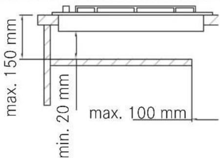
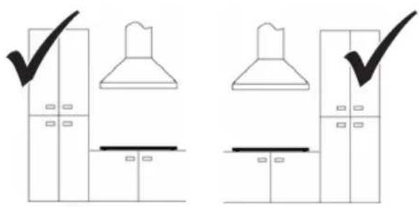
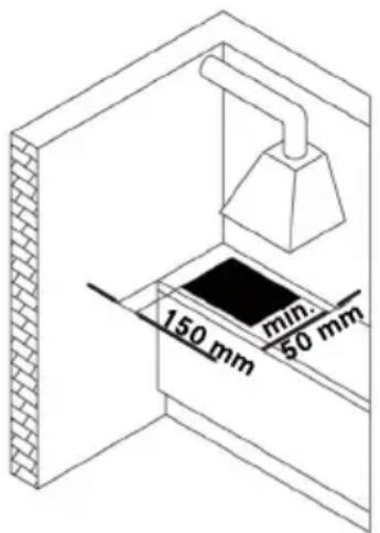
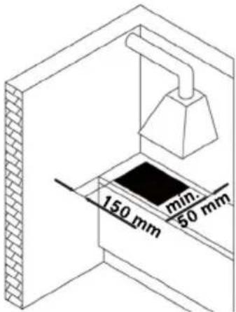
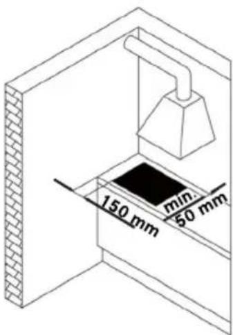
Suspended kitchen elements above the appliance must be installed at a distance that provided enough room for comfortable working process.
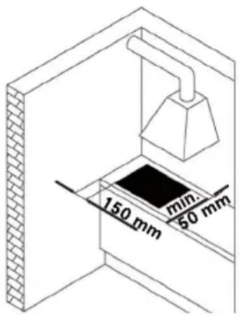
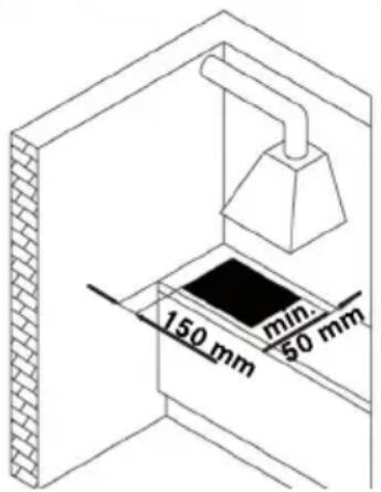
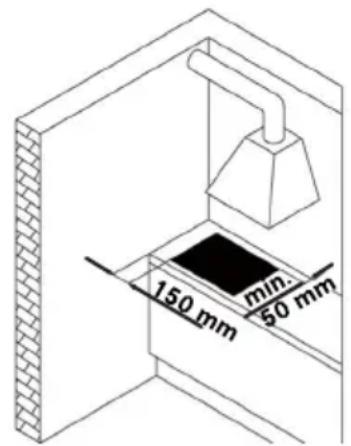
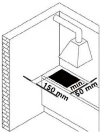
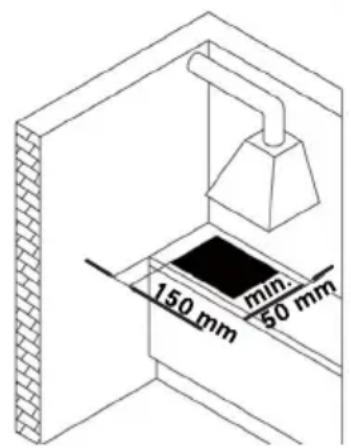
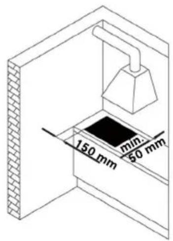
Important: These devices are „Y“ type with respect to the degree of protection against the dangers of fire. The use of hard wood decorative borders around the worktop behind the appliance is allowed, providing a minimum distance from the edge appliance of 50 mm for the side wall, 50 mm for the rear and 700 mm for any cabinets above it.
The appliance is recommended to be built into 50 mm thick worktops. In case the dimensions are different, eventual modifications have to be managed by the technician.

Ventilation of rooms
Make sure the room where the appliance is installed has permanent ventilation openings towards the outside or ventilation ducts to ensure an adequate air flow, as prescribed by the current regulations. All openings made must:
- Have a section of at least 100 cm²;
- Be made in such a way that they cannot be obstructed from inside or outside;
- Be provided with suitable protection to ensure that the ventilation opening is not reduced;
- Be at a suitable height from floor so that they do not hinder the exhausting of fumes.
If openings are made in the wall of an adjacent room, the latter must have direct ventilation and must not be:
- A bedroom
- A common area of the building
- A fire hazard area
Before testing and inspecting the appliance, make sure the room in which the ventilation opening is made does not have low pressure due to the operation of another user and that the ventilation between the two rooms is guaranteed by permanent free openings, for example by increasing the gap between the bottom of the door and the floor. The exhausting of fumes must occur by means of a hood which, in turn, must be connected to a chimney, flue, or directly to the outside.
Installation procedure
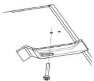
The appliance is fixed to the unit by means of the brackets and accessories provided.
▶ Make sure that there is free access to the two fixing elements in front after the installation of the appliance.
1
▶ Prepare the hole in the worktop according to the dimensions indicated.
▶ Mill the worktop along the entire edge of the hole made for built-in installation. Be sure to comply with the dimensions indicated.
2
▶ Refer to the information in chapter „Connection to gas supply“ before connecting the appliance.
▶ Connect the appliance to the gas supply.
3
▶ Refer to the information in chapter „Electrical connection“ before connecting the appliance.
▶ Connect the appliance to the power supply.
4
▶ Fit the appliance in the worktop correctly.
▶ Apply the sealing strip around the hole and position the hob.
▶ Fix the appliance with the screws and brackets.
▶ Remove any excess sealing strip.
5
If the appliance is not installed above an oven:
▶ Arrange a separator baffle.
6
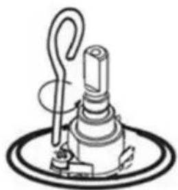
Minimum flame adjustment
▶ Remove the knobs (push-on type).
▶ Light the burners.
Adjust the minimum flame by turning the adjustment screw clockwise to decrease the flame and anticlockwise to increase it. The screwdriver for adjustment is supplied with the accessories.
Connection to gas supply
Connect the appliance to the gas supply in compliance with the current regulations, only after making sure it is arranged for the type of gas to be used. Otherwise, carry out the operations described in the section on „replacing injectors”.
For liquid gas use pressure regulators complying with the current regulations. Connection to the gas supply can be made in two ways:
A
▶ Connect the gas hob using a 12 mm diameter rigid copper pipe (3). To ensure a good seal, use the elastomer gasket supplied as an accessory (1).
B
▶ Connect the hob using a continuous-surface flexible steel tube (2).
Also in this case, to ensure a good seal use the gasket supplied as an accessory (1).
Make sure to comply with the current regulations on gas systems.
▶ After carrying out the connection use soapy water to check for any leaks.
Electrical connection
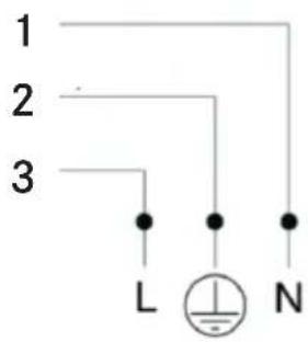
The FRANKE cooking hob comes with a 3-core power cable with free terminals.
▶ Make sure the characteristics of the household electrical system (voltage, maximum power and current) are compatible with those of the appliance.
If the appliance is to be permanently connected to the power supply:
▶ Install a device that enables disconnection from the power supply, with a contact opening distance (3 mm) that ensures complete disconnection in category III overvoltage conditions.
▶ Ensure the following:
- The characteristics of your household electrical power supply (voltage, maximum output and current) are compatible with those of your FRANKE hob.
- The plug and socket are suitable for a 16 A current.
- The plug and the socket can be easily reached and are positioned so that no live part is accessible when inserting or removing the plug.
- The plug can be inserted without difficulty and is accessible with the appliance installed.
- The appliance does not rest against the plug when installed in the worktop.
- A 3 x 0.75 mm² H05RR-F type cable for completely gas hobs is used when replacing the power cable.
- The terminals of two appliances are not connected to the same plug.
- The polarities of the free terminals (Blue = Neutral = (1) / Yellow and Green = Earth = (2) / Brown = Live = (3)) are respected.
REPAIR
If the power cable is damaged, it must be replaced by the manufacturer or the service or else by a person with similar qualifications, in order to avoid any risks.
Replacing injectors
Important: All the appliances are factory-set for natural gas (G20). If a different type of gas is to be used, change the injectors as follows:
Remove the grids, burner caps and flame-spreaders;
▶ Unscrew the injectors and replace them with those provided and suitable for the gas supply, making sure the marking matches that given in the table;
▶ Refit the flame-spreaders, burner caps and grids;
These burners do not require air adjustment.
Accessing the hob
To access the tray containing the functional parts, proceed as follows:
▶ Remove the grids, burner caps and flame-spreaders;
▶ Remove the knobs, sliding them off their pins;
▶ Remove the screws that fix the burners to the hob;
▶ Lift the hob.
Important : When converting the appliance to a different type of gas, place the corresponding sticker (supplied as an accessory) in the special space on the dataplate. For operation with LPG (G30 or G31), the minimum flame adjustment screw must be fully screwed down. These appliances are supplied in cat. II 2H3+.
Warning!
▷ Before attempting any repairs on the appliance, disconnect the power supply.
TECHNICAL DATA
▶ Refer to the data plate placed on the bottom side of the product.
Product identification
Appliance gas category: II 2H3+
Models: FH CR 301 1TC, FH CR 302 2G, FH CR 604 4G, FH CR 755 4G,
FH CR 905 4G, FH CR 1204 3G
This appliance complies with the following EC Directive: 90/396/EEC (Gas)
Further information on technical data is available on: www.franke.com
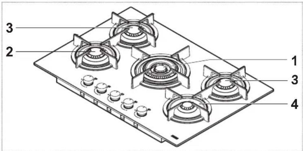
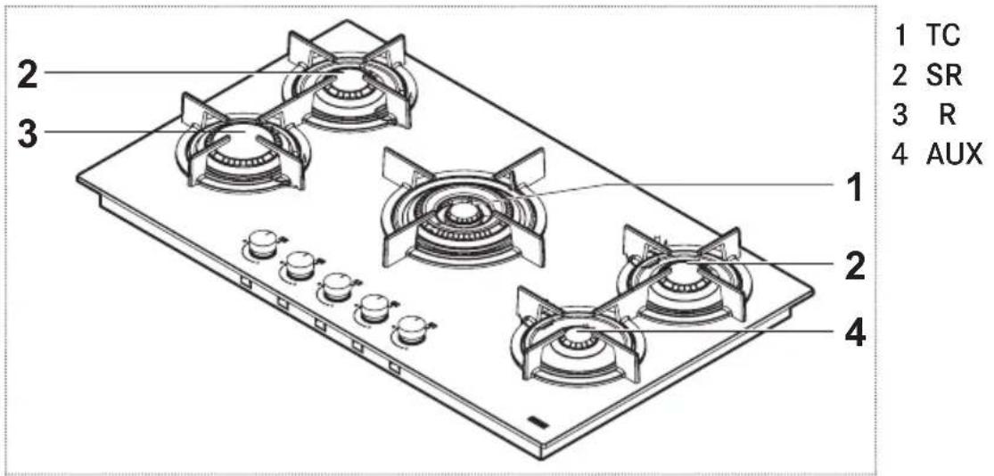
Power and burner values
Burner Rated power (kW) Reduced power (kW)
TC 4 1.8
R 3 0.7
SR 1.75 0.45
SR PLUS 1.9 0.45
AUX 1 0.3
Power and burner values
| Burner Rated | capacity G20 (m3/h) | Injectors G20 20 mbar (100/mm) | Rated capacity G30 / G31 (g/h) | Injectors G30 / G31 28-30/37 mbar (100/mm) |
| TC | 0.381 | E(2x1,01) + I(1x0,68) | 291 | E(2x0,68) + I(1x0,46) |
| R | 0.286 | 1.28 | 218 | 0,87 |
| SR | 0.167 | 1.03 | 127 | 0.67 |
| SR PLUS | 0.181 | 1.06 | 138 | 0.69 |
| AUX | 0.095 | 0.78 | 73 | 0.5 |
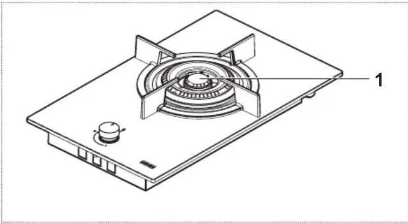
FH CR 301 1TC
natural_image
Technical line drawing of a gas stove with labeled component (1), showing internal fan and base plate (no text or symbols beyond label)1 TC
Parameter Value Dimensions (mm)
Working dimensions (W x D) - 310 x 510
Power supply voltage / frequency 220-240 V, 50/60 Hz
Power / Current 0.6 W / 16 A
Total installed gas rated power 4.00 kW
Total rated capacity - gas G20 0.381 m ^3 /h
Total rated capacity - gas G30 / G31 291 g/h
Air necessary for combustion (2 m ^3 /h 8.00
per kW of installed gas rated power)
| Parameter | Symbol | Value | Unit of measure |
| Appliance weight (gross / net) | M | 7.5 / 6.5 | kg |
| Number of burners | 1 | ||
| Heat source of each burner | Gas |
FH CR 302 2G
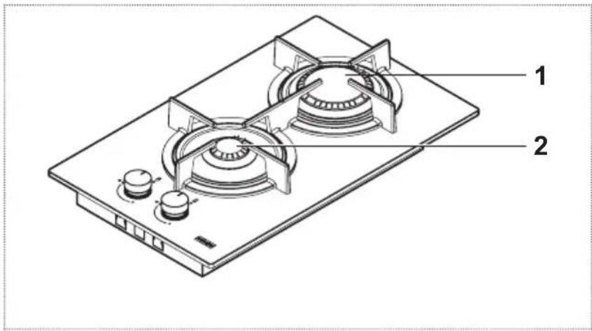
1 R
2 AUX
Parameter Value Dimensions (mm)
| Working dimensions (W x D) | - | 310 x 510 |
| Power supply voltage / frequency 220-240 V,50/60 Hz | - | |
| Power / Current 0.6 W / 16 A | ||
| Total installed gas rated power 4.00 kW | ||
| Total rated capacity - gas G20 0.381 m | ^3/h | |
| Total rated capacity - gas G30 / G31 291 g/h | ||
| Air necessary for combustion ( 2 m^3/h per kW of installed gas rated power) | 8.00 | |
| Parameter | Symbol | Value | Unit of measure |
| Appliance weight (gross / net) | M | 7.5 / 6.5 | kg |
| Number of burners | 2 | ||
| Heat source of each burner | Gas |
FH CR 604 4G
Parameter Value Dimensions (mm)
Working dimensions (W x D) - 590 x 510
Power supply voltage / frequency 220-240 V, 50/60 Hz
Power / Current 0.6 W / 16 A
Total installed gas rated power 7.50 kW
Total rated capacity - gas G20 0.715 m ^3 /h
Total rated capacity - gas G30 / G31 545 g/h
Air necessary for combustion (2 m ^3 /h 15.00 per kW of installed gas rated power)
| Parameter | Symbol | Value | Unit of measure |
| Appliance weight (gross / net) | M | 14 / 12 | kg |
| Number of burners | 4 | ||
| Heat source of each burner | Gas |
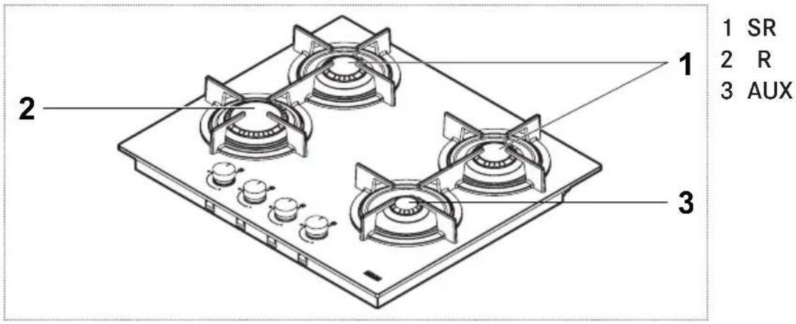
FH CR 755 4G TC
1 TC
2 SR
3 SR PLUS
4 AUX
Parameter Value Dimensions (mm)
Working dimensions (W x D) - 750 x 510
Power supply voltage / frequency 220-240 V, 50/60 Hz
Power / Current 0.6 W / 16 A
Total installed gas rated power 10.55 kW
Total rated capacity - gas G20 1.005 m ^3 /h
Total rated capacity - gas G30 / G31 767 g/h
Air necessary for combustion (2 m ^3 /h 21.10
per kW of installed gas rated power)
| Parameter | Symbol | Value | Unit of measure |
| Appliance weight (gross / net) | M | 18 / 15.5 | kg |
| Number of burners | 5 | ||
| Heat source of each burner | Gas |
FH CR 905 4G
Parameter Value Dimensions (mm)
Working dimensions (W x D) - 880 x 510
Power supply voltage / frequency 220-240 V, 50/60 Hz
Power / Current 0.6 W / 16 A
Total installed gas rated power 11.50 kW
Total rated capacity - gas G20 1.096 m ^3 /h
Total rated capacity - gas G30 / G31 836 g/h
Air necessary for combustion (2 m ^3 /h 23.00 per kW of installed gas rated power)
| Parameter | Symbol | Value | Unit of measure |
| Appliance weight (gross / net) | M | 19.5 / 17.5 | kg |
| Number of burners | 5 | ||
| Heat source of each burner | Gas |
FH CR 1204 3G TC
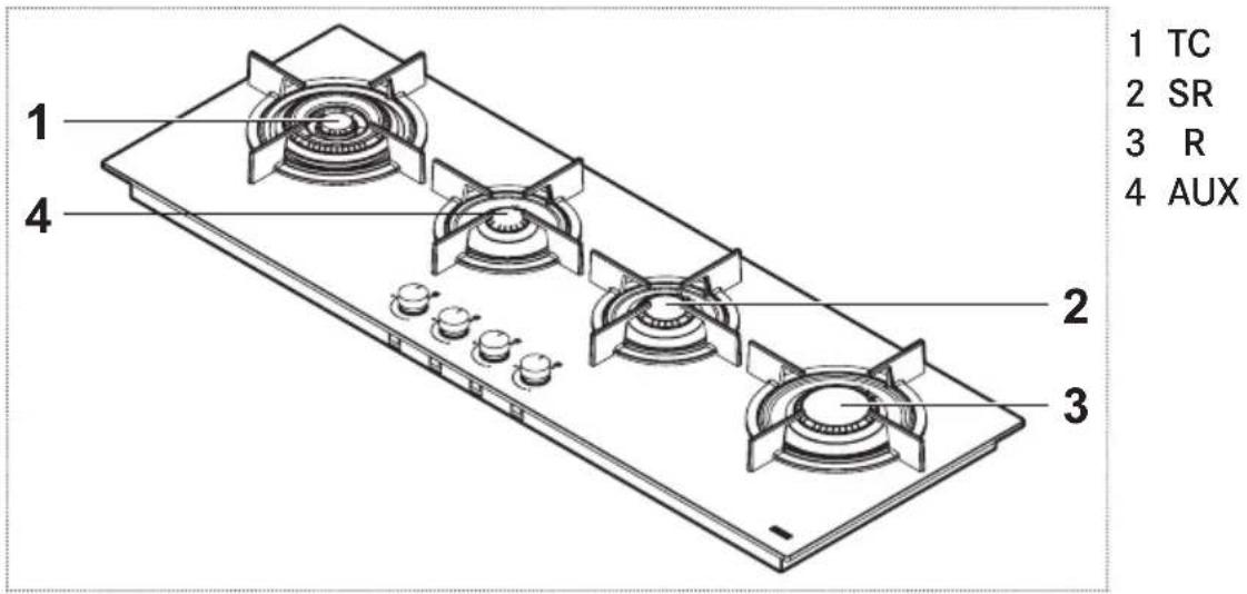
Parameter Value Dimensions (mm)
Working dimensions (W x D) - 1180 x 410
Power supply voltage / frequency 220-240 V, 50/60 Hz
Power / Current 0.6 W / 16 A
Total installed gas rated power 9.75 kW
Total rated capacity - gas G20 0.929 m ^3 /h
Total rated capacity - gas G30 / G31 709 g/h
Air necessary for combustion (2 m ^3 /h 19.50 per kW of installed gas rated power)
| Parameter | Symbol | Value | Unit of measure |
| Appliance weight (gross / net) | M | 24 / 18.5 | kg |
| Number of burners | 4 | ||
| Heat source of each burner | Gas |
INSTALLATION
Raumbelüftung
natural_image
Technical line drawing of a gas stove with labeled component (1), showing internal fan and base plate (no text or symbols beyond label)1 TC
Parameter Wert Maße (mm)
1 R
2 AUX
Parameter Wert Maße (mm)
Parameter Wert Maße (mm)
1 TC
2 SR
3 SR PLUS
4 AUX
Parameter Wert Maße (mm)
Parameter Wert Maße (mm)
Parameter Wert Maße (mm)
natural_image
Technical line drawing of a gas stove with labeled component (1), showing internal fan and base plate (no text or symbols beyond label)1 TC
1 R
2 AUX
1 TC
2 SR
3 SR PLUS
4 AUX
natural_image
Technical line drawing of a gas stove with labeled component (1), showing internal fan and base plate (no text or symbols beyond label)1 TC
1 R
2 AUX
1 TC
2 SR
3 SR PLUS
4 AUX

natural_image
Technical line drawing of a gas stove with labeled component (1), showing internal fan and base plate (no text or symbols beyond label)1 TC
1 R
2 AUX
1 TC
2 SR
3 SR PLUS
4 AUX
natural_image
Technical line drawing of a gas stove with labeled component (1), showing internal fan and base plate (no text or symbols beyond label)1 TC
1 R
2 AUX
1 TC
2 SR
3 SR PLUS
4 AUX
natural_image
Technical line drawing of a gas stove with labeled component (1), showing internal fan and base plate (no text or symbols beyond label)1 TC
1 R
2 AUX
1 TC
2 SR
3 SR PLUS
4 AUX
natural_image
Diagram showing two identical kitchen cabinets with one emitting a smokestack and the other emitting a smokestack, both marked with checkmarks (no text or symbols present)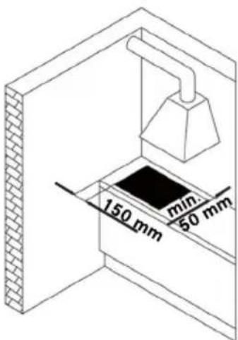
natural_image
Technical line drawing of a gas stove with labeled component (1), showing internal fan and base plate (no text or symbols beyond label)1 TC
1 R
2 AUX
1 TC
2 SR
3 SR PLUS
4 AUX
Větrání místností
natural_image
Technical line drawing of a gas stove with labeled component (1), showing internal fan and base plate (no text or symbols beyond label)1 TC
1 R
2 AUX
1 TC
2 SR
3 SR PLUS
4 AUX
natural_image
Technical line drawing of a gas stove with labeled component (1), showing internal fan and base plate (no text or symbols beyond label)1 TC
1 R
2 AUX
1 TC
2 SR
3 SR PLUS
4 AUX
natural_image
Technical line drawing of a gas stove with labeled component (1), showing internal fan and base plate (no text or symbols beyond label)1 TC
Parametri Valoare Dimensiuni (mm)
1 R
2 AUX
Parametri Valoare Dimensiuni (mm)
Parametri Valoare Dimensiuni (mm)
Dimensiuni de lucru (L x A) - 590 x 510
1 TC
2 SR
3 SR PLUS
4 AUX
Parametri Valoare Dimensiuni (mm)
Dimensiuni de lucru (L x A) - 750 x 510
Parametri Valoare Dimensiuni (mm)
Dimensiuni de lucru (L x A) - 880 x 510
Parametri Valoare Dimensiuni (mm)
Dimensiuni de lucru (L x A) - 1180 x 410
natural_image
Technical line drawing of a gas stove or fan with labeled component (no text or symbols beyond label)1 TK
1 5
2 ВСП
natural_image
Simple line drawing of a kitchen cabinet with a checkmark and a hood, no text or symbols present.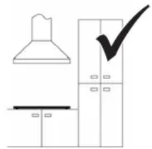
natural_image
Simple line drawing of a kitchen interior with a hood, cabinet, and checkmark (no text or symbols)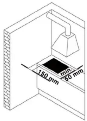
natural_image
Technical line drawing of a gas stove with labeled component (1), showing internal fan and base plate (no text or symbols beyond label)1 TC
1 R
2 AUX
1 TC
2 SR
3 SR PLUS
4 AUX
房间通风
natural_image
Isometric line drawing of a gas stove or fan with labeled component (no text or symbols beyond label)1 TC
参数 值 尺寸(mm)
1 R
2 AUX
参数 值 尺寸(mm)
参数 值 尺寸(mm)
1 TC
2 SR
3 SR PLUS
4 AUX
参数 值 尺寸(mm)
参数 值 尺寸(mm)
参数 值 尺寸 (mm)
2 SR
3 R _2
4 AUX
1
2
4
natural_image
Isometric line drawing of a gas stove or fan with labeled component (1), no text or symbols present.natural_image
Simple line drawing of a kitchen cabinet with a checkmark and a smoke hood (no text or symbols)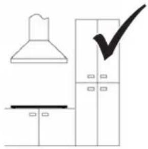
natural_image
Simple line drawing of a kitchen interior with a chimney, cabinet, and checkmark (no text or symbols)تهوية الغرف
Franke Kitchen System SARL
21 000 Casablanca
Phone +212 522 674 200
Norway
Franke KS Norway
8520 Lystrup, Denmark
Phone +47 35 566 450
Poland
Franke Polska Sp. z o.o.
05-090 Raszyn
Phone +48 22 711 6700
Portugal
Franke Portugal S.A.
2735-531 Cacém
Phone +351 21 426 9670
Romania
Franke Romania SRL
Pantelimon 077145
Phone +40 21 350 1550
Russia
Franke Russia GmbH
199106 St. Petersburg
Phone +7 812 703 1540
Slovak Republic
Franke Slovakia s.r.o.
010 01 Žilina
Phone +421 41 733 6200
South Africa
Franke South Africa
Durban 4052
Phone +27 31 450 6300
Spain
Phone +46 912 405 00
Switzerland
United Arab Emirates
Franke LLC
Ras Al Khaimah
Phone +971 7 203 4700
United Kingdom
Franke UK Ltd.
Manchester M22 5WB
Phone +44 161 436 6280
USA
Franke Kitchen Systems LLC
Smyrna, TN 37167
Phone 800 626 5771

- INSTALLATION
- Identification plate
- Cabinet requirements
- Ventilation of rooms
- Installation procedure
- 1
- 2
- 3
- 4
- 5
- 6
- Minimum flame adjustment
- Connection to gas supply
- A
- B
- Electrical connection
- REPAIR
- Replacing injectors
- Accessing the hob
- Warning!
- TECHNICAL DATA
- Product identification
- Power and burner values
- Burner Rated power (kW) Reduced power (kW)
- Parameter Value Dimensions (mm)
- Raumbelüftung
- Parameter Wert Maße (mm)
- Větrání místností
- Parametri Valoare Dimensiuni (mm)
- 房间通风
- تهوية الغرف
- Norway
- Poland
- Portugal
- Romania
- Russia
- Slovak Republic
- South Africa
- Spain
- Switzerland
- United Arab Emirates
- United Kingdom
- USA
Brand : FRANKE
Model : Crystal FHCR 302 2G HE
Category : Cooker