
PE 8-4 80 - Grinder Flex - Free user manual and instructions
Find the device manual for free PE 8-4 80 Flex in PDF.

| Product type | Polisher (grinder) |
| Model | PE 8-4 80 |
| Brand | Flex |
| Max. tool diameter | 80 mm |
| Spindle diameter | M14 |
| No-load speed | 1300 – 3900 rpm |
| Rated speed | 4400 rpm |
| Power input | 800 W |
| Power output | 325 W |
| Weight (without cord) | 1.9 kg |
| Protection class | II (double insulation) |
| Power cord length | 4.0 m |
| Sound pressure level | 80 dB(A) |
| Sound power level | 91 dB(A) |
| Total vibration value (sanding) | < 2.5 m/s² |
| Power supply | Mains, 230 V (according to rating plate) |
| Main functions | Polishing, buffing with sponge, fleece, felt, soft disc |
| Maintenance and cleaning | Regular cleaning of ventilation slots, replacement of carbon brushes with original parts |
| Safety | Spindle lock, rocker switch with lock-off, overload protection |
| Spare parts and repairability | Exploded views and lists on www.flex-tools.com, repairs at authorized service center |
| General information | Professional use in industry and trade |
Frequently Asked Questions - PE 8-4 80 Flex
User questions about PE 8-4 80 Flex
0 question about this device. Answer the ones you know or ask your own.
Ask a new question about this device
Download the instructions for your Grinder in PDF format for free! Find your manual PE 8-4 80 - Flex and take your electronic device back in hand. On this page are published all the documents necessary for the use of your device. PE 8-4 80 by Flex.
USER MANUAL PE 8-4 80 Flex
natural_image
Illustration of a mechanical power tool with a screw base and cylindrical body (no text or symbols)1 S p i n d e l
natural_image
Close-up of a car door handle with a stylized exhaust grille and a black arrow pointing to the grille (no text or symbols)natural_image
Close-up of a car's front grille with a numbered knob and directional arrows (no text or symbols)natural_image
Mechanical assembly diagram showing a rotating component with a downward arrow indicating motion (no text or symbols)Manager Research & Development (R & D)
Symbols used in this manual ..... 12
Technical specifications ..... 12
Overview 13
For your safety 14
Noise and vibration ..... 16
Operating instructions 16
Maintenance and care 18
Disposal information ..... 19
C€-Declaration of Conformity ..... 19
Symbols used in this manual

WARNING!
Denotes impending danger. Non-observance of this warning may result in death or extremely severe injuries.

CAUTION!
Denotes a possibly dangerous situation.
Non-observance of this warning may result insight injury or damage to property.

NOTE
Denotes application tips and important information.
Symbols on the power tool

Before switching on the power tool, read the operating manual!

Wear goggles!

Disposal information for the old machine (see page 19)!
Technical specifications
| Machine type | Polisher PE 8-4 80 | |
| Tool ∅ max. mm 80 | ||
| Spindle diameter M14 | ||
| Idle speed r.p.m. 1300–3900 | ||
| Rated speed r.p.m. 4400 | ||
| Power input W 800 | ||
| Power output | W | 325 |
| Weight (without power cord) | kg | 1.9 |
| Protection class | II / ☐ | |
Overview
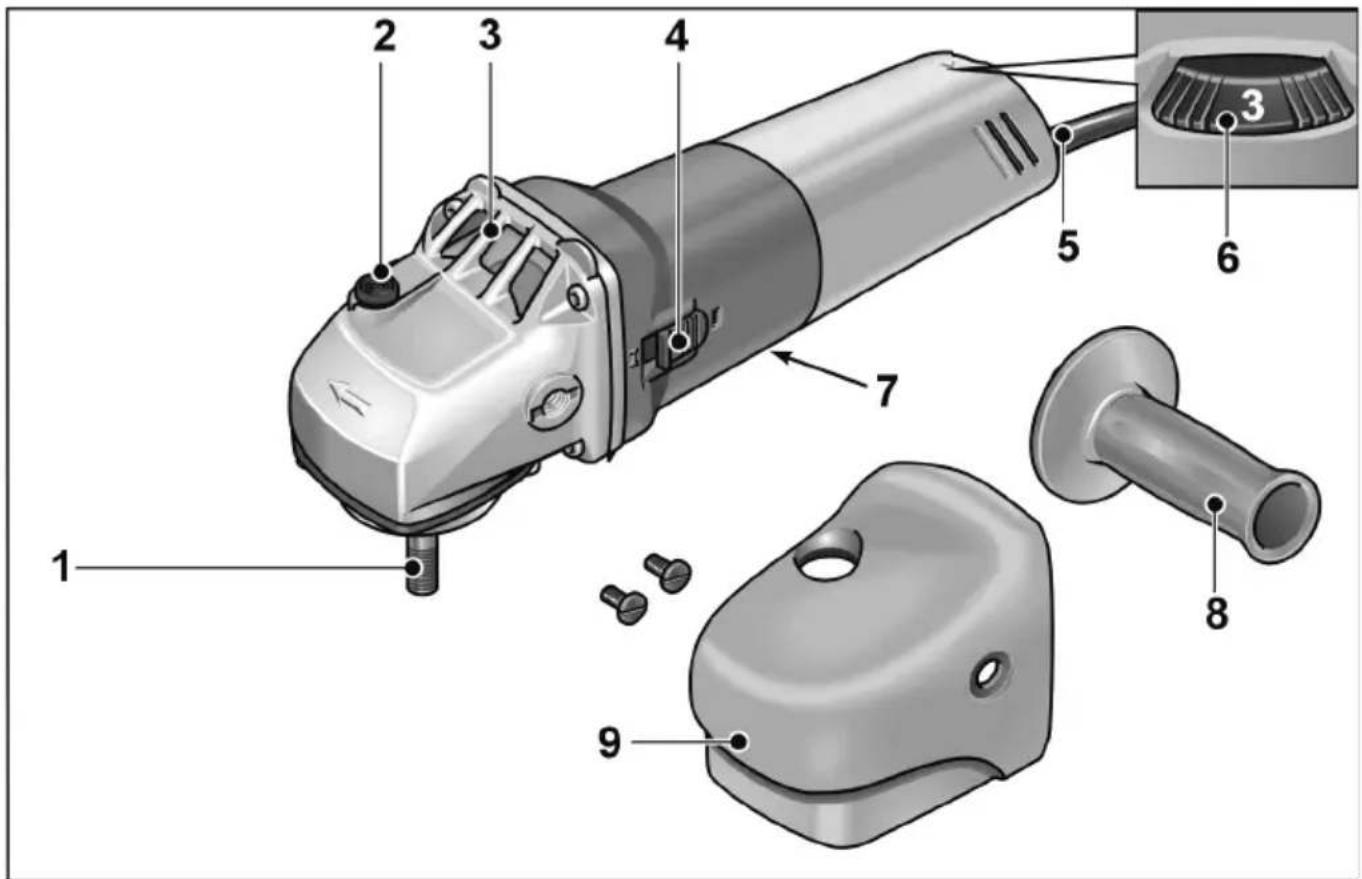
1 S p i n d l e
2 S p i n d l e l
Secures the spindle when the tool is changed.
3 Gear head
With air outlet and direction-of-rotation arrow.
4 S w i t c h r o c k e r
For switching on and off. With notched position for continuous operation.
5 4.0 m power cord with plug
6dDial for preselecting the speed
7 Rating plate
8 H a n d l e
9 Handle cover
For your safety

WARNING!
Before using the polisher, please read and follow:
– these operating instructions,
- the "General safety instructions" on the handling of power tools in the enclosed booklet (leaflet-no.:315.915),
– the currently valid site rules and the regulations for the prevention of accidents.
This polisher is state-of-the-art and has been constructed in accordance with the acknowledged safety regulations.
Nevertheless, when in use, the power tool may be a danger to life and limb of the user or a third party, or the power tool or other property may be damaged. The polisher may be used only
-used as intended,
-in perfect working order.
Faults which impair safety must be repaired immediately.
Intended use
This polisher is designed
– for commercial use in industry and trade,
- for all types of polishing work with polishing sponges, lambskins and woolskins, felt plate, buffing disc
- for use with polishing tools which are permitted to run at a speed of at least 3900 r.p.m.
Safety instructions for polishing

WARNING!
Read all safety instructions and other instructions. Failure to observe the safety instructions and other instructions may result in an electric shock, fire and/or serious injuries. Keep all safety instructions and other instructions in a safe place for the future.
This electric power tool must be used as a polisher. Observe all safety information, instructions, diagrams and data which you receive with the power tool. If you do not observe the following instructions, an electric shock, fire and/or serious injuries may occur.
■ This electric power tool is not suitable for grinding, sanding, for use with wire brushes or for cut-off grinding. If the electric power tool is not used as intended, the user may be exposed to hazards and may be injured.
■ Never use accessories which the manufacturer did not intend or recommend especially for this electric power tool. Just because you can attach the accessory to your electric power tool does not guarantee safe use.
■ The permitted speed of the insertion tool must be at least as high as the maximum speed indicated on the electric power tool. An accessory which rotates faster than permitted may shatter and fly off.
■ Outer diameter and thickness of the insertion tool must correspond to the dimensions of the electric power tool.
Incorrectly measured insertion tools cannot be adequately shielded or controlled.
■ Flanges or other accessories must fit exactly on the spindle of your electric power tool. Insertion tools, which do not fit exactly on the spindle of the electric power tool, rotate unevenly, vibrate violently and may result in loss of control.
■ Do not use any damaged insertion tools. Before use, always check the insertion tools for splinters and cracks. If the electric power tool or the insertion tool is dropped, check for damage or use an undamaged insertion tool. When you have checked and inserted the tool, ensure that you and anybody in the vicinity remain outside the plane of the rotating insertion tool and leave the power tool running for one minute at maximum speed. Damaged insertion tools usually break during this test time.
■ Wear personal protective equipment. Depending on the application, wear full face protection, eye protection or goggles. If appropriate, wear a dust mask, hearing protection, protective gloves and/or a special apron which protect you from small material particles. You should protect your eyes from foreign objects which are ejected for different applications. Dust and respirator masks must filter the dust which is generated by the power tool for the particular application. If you are exposed to loud noise for a prolonged period, you may suffer hearing loss.
■ Ensure that other persons are situated at a safe distance from the work area. Anyone who enters the work area must wear personal protective equipment.
Fragments of the workpiece or broken insertion tools may fly off and cause injuries even outside the direct working area.
■ If the insertion tool is at risk of coming into contact with concealed power cables or the power cord itself, hold the power tool by the insulated grip surfaces only.
Contact with a live cable may also cause metal parts of the appliance to become live and result in an electric shock.
- Keep the power cord away from rotating insertion tools. If you lose control of the appliance, the power cord could be severed or become caught and your hand or arm may strike the rotating insertion tool.
■ Never put down the electric power tool until the insertion tool has come to a standstill. The rotating insertion tool may come into contact with the support surface, possibly resulting in you losing control of the electric power tool.
■ Never leave the electric power tool running while you are carrying it. Your clothing may become caught by accidental contact with the rotating insertion tool which may then drill into your body.
■ Regularly clean the ventilation slots on your electric power tool. The motor fan draws dust into the housing; a large build-up of metal dust may cause electrical hazards.
■ Never use the electric power tool near combustible materials. Sparks may ignite these materials.
■ Never use insertion tools which require liquid coolants. The use of water or other liquid coolants may result in electric shock.
■ Do not allow any loose parts of the polishing hood, in particular fixing cords. Stow or shorten the fixing cords. Loose, entrained fixing cords may trap your fingers or become entangled in the workpiece.
Recoil and appropriate safety instructions
Recoil is the sudden reaction caused by a rotating insertion tool which sticks or is blocked. A rotating insertion tool which sticks or is blocked stops abruptly. As a result, an uncontrolled electric power tool is accelerated against the direction of rotation of the insertion tool at the blocking point. A recoil occurs if the electric power tool is used incorrectly or improperly. A recoil can be prevented by appropriate precautions as described below.
■ Hold the electric power tool firmly and position your body and arms to allow you to absorb kickback forces. If fitted, always use the auxiliary handle to ensure the best possible control over the recoil forces or reaction torques when acceleration occurs. The operator can control kickback and reaction forces by taking appropriate precautions.
- Keep your hands away from the rotating insertion tool. The insertion tool may kickback over your hand.
- Keep your body out of the area into which the electric power tool moves when a recoil occurs. Kickback propels the electric power tool in the direction opposite to the movement of the polisher at the point of pinching.
■ Work especially carefully near corners, sharp edges, etc. Prevent the insertion tool from recoiling off the workpiece and jamming. The rotating insertion tool has a tendency to snag on corners, sharp edges or if it bounces. This causes a loss of control or kickback.
■ Do not use a chain or toothed saw blade. Such insertion tools frequently cause a kickback or the loss of control of the electric power tool.
Additional safety instructions
The mains voltage and the voltage specifications on the rating plate must correspond.
Do not press the spindle lock until the tool stops.
Noise and vibration
The noise and vibration values have been determined in accordance with EN 60745.
The A evaluated noise level of the power tool is typically:
– Sound pressure level: 80 dB(A);
– Sound power level: 91 dB(A);
– Uncertainty: K
Total vibration value (when polishing painted surfaces):
- Emission value: a h = 2.5 m^2/s
– Uncertainty: K

CAUTION!
The indicated measurements refer to new power tools. Daily use causes the noise and vibration values to change.

NOTE
The vibration emission level given in this information sheet has been measured in accordance with a standardised test given in EN 60745 and may be used to compare one tool with another. It may be used for a preliminary assessment of exposure. The declared vibration emission level represents the main applications of the tool.
However if the tool is used for different applications, with different accessories or poorly maintained, the vibration emission may differ.
This may significantly increase the exposure level over the total working period.
For a precise estimation of the vibration load the times should also be considered during which the power tool is switched off or even running, but not actually in use.
This may significantly increase the exposure level over the total working period. Identify additional safety measures to protect the operator from the effects of vibration such as: maintain the tool and the accessories, keep the hands warm, organisation of work patterns.

CAUTION!
Wear ear protection at a sound pressure above 85 dB(A).
Operating instructions

WARNING!
Before carrying out any work on the polisher, always pull out the mains plug.
Before switching on the power tool
Unpack the polisher and check that there are no missing or damaged parts. = 1.5 m/s
Attach handle cover
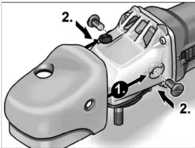
■ Loosen screws or handle.
■ Push on handle cover (1.).
■ Tighten screws (2.).
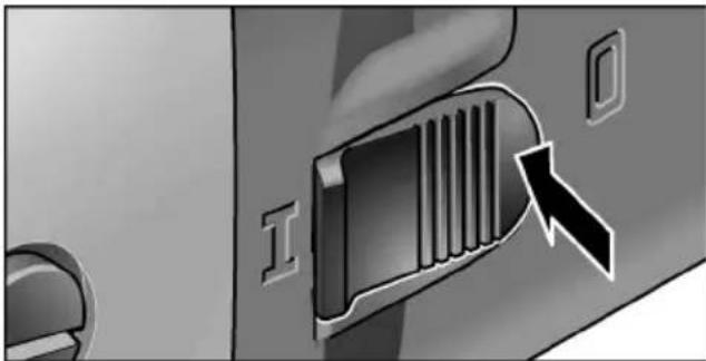
Switching on and off
Brief operation without engaged switch rocker:
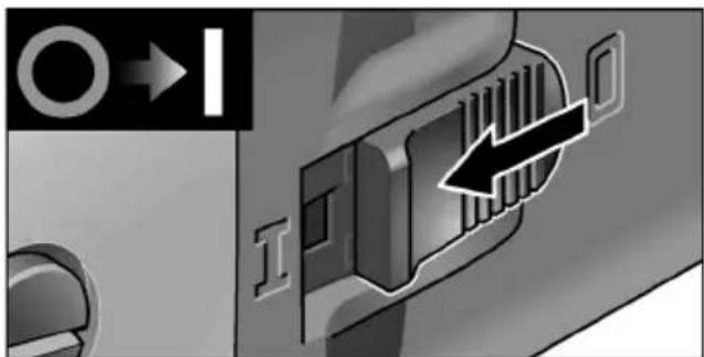
■ Push the switch rocker forwards and hold in position.
■ To switch off the power tool, release the switch rocker.
Continuous operation with engaged switch rocker:

CAUTION!
Following a power failure, the switched-on machine will start running again.
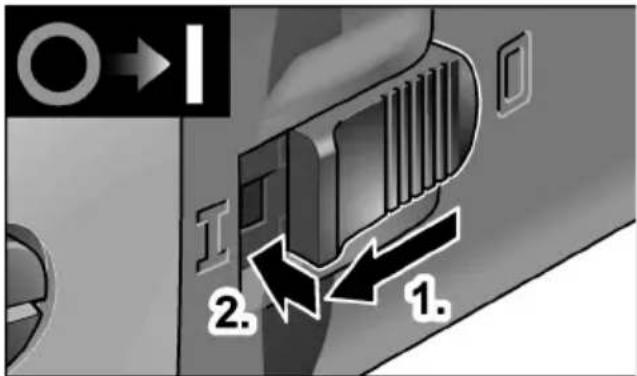
■ Push the switch rocker forwards and engage by pressing the front end.
natural_image
Close-up of a door handle with a grille and a directional arrow (no text or symbols)■ To switch off the power tool, release the switch rocker by pressing the rear end.
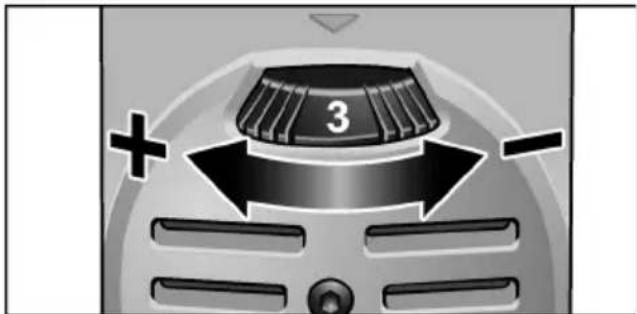
Preselecting the speed
natural_image
Close-up of a car's front grille with a numbered knob and directional arrows (no text or symbols)■ To set the operating speed, move the dial to the required value.

CAUTION!
Risk of injury due to destruction of the tool. Use the appropriate tool for the job.

NOTE
If an overload or overheating occurs during continues operation, the power tool automatically reduces the speed until the power tool has cooled down adequately.
Attaching or changing the tool holder
■ Pull out the mains plug.
■ Press and hold down the spindle lock.
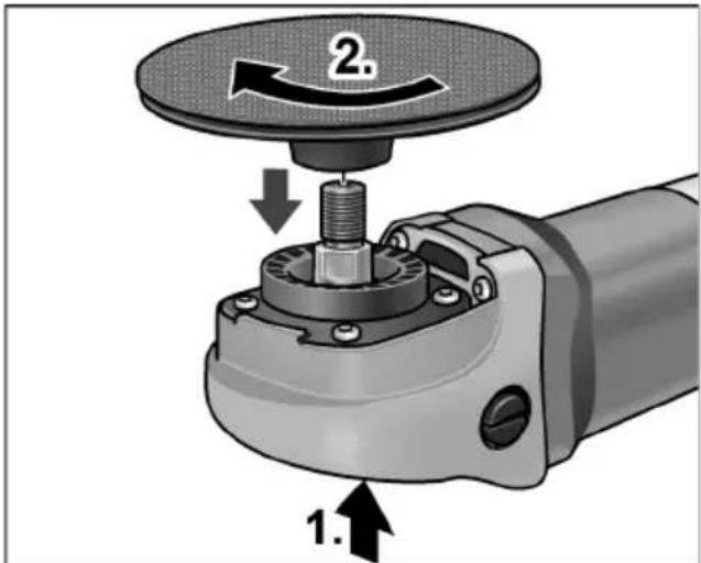
■ Screw chuck clockwise onto the spindle and tighten hand-tight.
To loosen, turn chuck anti-clockwise.
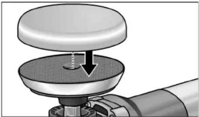
Attach or change tools
■ Pull out the mains plug.
natural_image
Mechanical assembly diagram showing a rotating component with a downward arrow indicating motion (no text or symbols)■ Press polishing agent firmly in the centre of the Velcro pad. Use undamaged polishing tools only.
- Carry out a test run to check that the tool is clamped in the centre.
Operating instructions

NOTE
When the power tool is switched off, the tool continues running briefly.
- If using a polishing paste, use the respective tool for each paste.
- In the case of sensitive surfaces (e. g. car paint) do not work aggressively, but at low speeds and with low contact pressure.
- Sponges can be washed in the washing machine.
Maintenance and care

WARNING!
Before carrying out any work on the polisher, always pull out the mains plug.
Cleaning

WARNING!
If metals are work over a prolonged period, conductive dust may become deposited inside the housing. Impairment of the protective insulation! Operate the power tool via a residual-current-operated circuit-breaker (tripping current 30 mA).
Regularly clean the power tool and ventilation slots. Frequency of cleaning is dependent on the material and duration of use.
Regularly blow out the housing interior and motor with dry compressed air.
Carbon brushes
The polisher features cut-off carbon brushes. When the wear limit of the cut-off carbon brushes is reached, the polisher switches off automatically.

NOTE
Use only original parts supplied by the manufacturer for replacement purposes. If non-original parts are used, the guarantee obligations of the manufacturer will be deemed null and void.
When the polisher is being used, the carbon brushes can be seen sparking through the rear air inlet apertures.
If the carbon brushes spark excessively, switch off the polisher immediately. Take the polisher to a customer service workshop authorised by the manufacturer.
Gears

NOTE
Do not loosen the screws on the gear head during the warranty period. Non-compliance will deem the guarantee obligations of the manufacturer null and void.
Repairs
Repairs may be carried out by an authorised customer service centre only.
Spare parts and accessories
For other accessories, in particular tools and polishing aids, see the manufacturer's catalogues.
Exploded drawings and spare-part lists can be found on our homepage:
www.flex-tools.com
Disposal information

WARNING!
Render redundant power tools unusable byremoving the power cord.

Only for EU countries
Do not dispose of electric tools together with household waste material!
In observance of European Directive 2012/19/EC on waste electrical and electronic equipment and its implementation in accordance with national law, electric tools that have reached the end of their life must be collected separately and returned to an environmentally compatible recycling facility.

NOTE
Please ask your dealer about disposal options for redundant power tools.
CE -Declaration of Conformity
We declare under our sole responsibility that the product described under “Technical Data” conforms to the following standards or normative documents:
EN 60745 in accordance with the regulations of the directives 2004/108/EC (until 19.04.2016), 2014/30/EU (from 20.04.2016), 2006/42/EC, 2011/65/EC.
Responsible for technical documents: FLEX-Elektrowerkzeuge GmbH, R & D Bahnhofstrasse 15, D-71711 Steinheim/Murr

Manager Research &
Development (R & D)
1 B r o c h e
natural_image
Close-up of a car air vent with a grille and directional arrow (no text or symbols)natural_image
Close-up of a car's front grille with a knob labeled '3' and directional arrows indicating motion (no text or symbols beyond the number)natural_image
Mechanical assembly diagram showing a rotating component with a downward arrow indicating motion (no text or symbols)Manager Research & Development (R & D)
Klaus Peter WeinperEckhard Rühle Head of Quality Department (QD)
08.05.2015
1 Alberino
2 Arresto alberino
■ Allentare le viti o l'impugnatura.
■ Inserire la cuffia con maniglia (1.).
■ Stringere le viti (2.).
natural_image
Close-up of a car door handle with a stylized exhaust grille and directional arrow (no text or symbols)natural_image
Close-up of a car's front grille with a numbered knob and directional arrows (no text or symbols)natural_image
Mechanical assembly diagram showing a rotating component with a downward arrow indicating motion (no text or symbols)natural_image
Close-up of a door handle with a grille and a black arrow pointing to the grille (no text or symbols visible)natural_image
Close-up of a kitchen fan with a knob labeled '3' and directional arrows indicating motion (no text or symbols beyond the number)natural_image
Mechanical assembly diagram showing a rotating component with a downward arrow indicating motion (no text or symbols)Manager Research & Development (R & D)
natural_image
Close-up of a car door handle with a stylized grille and arrow icon (no text or symbols)natural_image
Close-up of a car's front grille with a knob labeled '3' and directional arrows (+/-), no readable text or symbols beyond the number.natural_image
Mechanical assembly diagram showing a rotating component with a downward arrow indicating motion (no text or symbols)Manager Research & Development (R & D)
Klaus Peter WeinperEckhard F Head of Quality Department (QD)
08.05.2015
natural_image
Close-up of a car door handle with a grille and a button, no visible text or symbolsnatural_image
Close-up of a car's front grille with a numbered knob and directional arrows (no text or symbols)natural_image
Mechanical assembly diagram showing a rotating component with a downward arrow indicating motion (no text or symbols present)Manager Research &
Development (R & D)
1 S p i n d e l
2 Spindellås
natural_image
Close-up of a mechanical component with a black arrow pointing to a textured surface (no visible text or symbols)■ Skub vippekontakten fremad og hold den fast.
■ Slip vippekontakten for at slukke.
Konstant drift med indgreb:

FORSIGTIG!
natural_image
Close-up of a door handle with a heat sink and arrow indicator (no text or symbols)■ Frigør vippekontakten ved at trykke på bagerste ende for at slukke.
natural_image
Close-up of a car's front grille with a numbered knob and directional arrows (no text or symbols)natural_image
Mechanical assembly diagram showing a rotating component with a downward arrow indicating motion (no text or symbols present)Manager Research & Development (R & D)
Klaus Peter WeinperEckhard F Head of Quality Department (QD)
08.05.2015
1 S p i n d e l
2 S p i n d e l s
natural_image
Close-up of a car's front panel showing a grille and a directional arrow (no text or symbols)natural_image
Close-up of a car's front grille with a numbered knob and directional arrows (no text or symbols)natural_image
Mechanical assembly diagram showing a rotating component with a downward arrow indicating motion (no text or symbols)Manager Research & Development (R & D)
1 S p i n d e l
2 Spindellås
natural_image
Close-up of a door handle with a grille and a black arrow pointing to the grille (no text or symbols visible)natural_image
Close-up of a car's front grille with a knob labeled '3' and directional arrows (+/-), no readable text or symbols beyond the number.natural_image
Mechanical component diagram showing a knob pressing down on a base with a downward arrow indicating force or movement (no text or symbols present)Manager Research & Development (R & D)
Head of Quality Department (QD)
1 Kara
2 Karalukko
natural_image
Close-up of a door handle with a heat sink and arrow indicating direction (no text or symbols)natural_image
Close-up of a car's front grille with a knob labeled '3' and directional arrows (+/-), no readable text or symbols beyond the number.natural_image
Mechanical assembly diagram showing a rotating component with a downward arrow indicating motion (no text or symbols)1 'A τ ρ α κ τ ος
2 Ασφάλιση ατράκτου
natural_image
Close-up of a door handle with a stylized grille and arrow indicator (no text or symbols)natural_image
Close-up of a car's front grille with a knob labeled '3' and directional arrows (+/-), no readable text or symbols beyond the number.natural_image
Mechanical assembly diagram showing a rotating component with a downward arrow indicating motion (no text or symbols present)Manager Research & Development (R & D)
1 W r z e c i o n
2 Blokada wrzeciona
natural_image
Close-up of a car air vent with a grille and directional arrow (no text or symbols)natural_image
Close-up of a car's air vent with a numbered knob and directional arrows (no text or symbols)natural_image
Mechanical assembly diagram showing a rotating component with a downward arrow indicating motion (no text or symbols)Manager Research & Development (R & D)
Klaus Peter WeinperEckhard F Head of Quality Department (QD)
08.05.2015
1 O r s ó
2 Orsórögzítés
natural_image
Close-up of a door handle with a stylized arrow pointing to a grille (no text or symbols)natural_image
Close-up of a car dashboard with a knob labeled '3' and directional arrows indicating motion (no text or symbols beyond the number)natural_image
Mechanical assembly diagram showing a rotating component with a downward arrow indicating motion (no text or symbols)EN 60745, a 2004/108/EK
(2016. 04. 19-ig), 2014/30/EK
(2016. 04. 20-töl), a 2006/42/EK,
Manager Research & Development (R & D)
1 V ř e t e n o
2 A r e t a c e v
natural_image
Close-up of a door handle with a grille and a directional arrow (no text or symbols)natural_image
Close-up of a car's front grille with a numbered knob and directional arrows (no text or symbols)natural_image
Mechanical assembly diagram showing a rotating component with a downward arrow indicating motion (no text or symbols present)Manager Research & Development (R & D)
Klaus Peter WeinperEckhard Rühle Head of Quality Department (QD)
08.05.2015
1 V r e t e n o 2 A r e t á c i a
■ Povol'te skrutky alebo rukovät.
■ Nasuňte uchopovací kryt (1.).
■ Skrutky pevne utiahnite (2.).
Zapnutie a vypnutie
natural_image
Close-up of a car door handle with a grille and a black arrow pointing to the grille (no text or symbols)natural_image
Close-up of a car dashboard with a knob labeled '3' and directional arrows (+/-), no readable text or symbols beyond the number.natural_image
Mechanical assembly diagram showing a rotating component with a downward arrow indicating motion (no text or symbols)Manager Research &
Development (R & D)
1 Spin d e l
2 Spindli lukustus
natural_image
Close-up of a door handle with a grille and a black arrow pointing to the grille (no text or symbols visible)natural_image
Close-up of a car's air vent with a knob labeled '3' and directional arrows (+/-), no readable text or symbols beyond the number.natural_image
Mechanical component diagram showing a rotating knob with a downward arrow indicating force or movement (no text or symbols)Manager Research & Development (R & D)
Klaus Peter WeinperEckhard F
Head of Quality
Department (QD)
08.05.2015
1 Velenas
2 Veleno fiksatorius
natural_image
Close-up of a car door handle with a grille and a directional arrow (no text or symbols)natural_image
Close-up of a car's front grille with a knob labeled '3' and directional arrows (+/-), no readable text or symbols beyond the number.natural_image
Mechanical assembly diagram showing a rotating component with a downward arrow indicating motion (no text or symbols present)Manager Research &
Development (R & D)
Klaus Peter WeinperEckhard F
Head of Quality
Department (QD)
08.05.2015
1 D a r b v ārpsta
■ Atlaidiet skrūves vai rokturi.
■ Uzbīdiet roktura apvalku (1.).
■ Pievelciet skrūves (2.).
natural_image
Close-up of a door handle with a ventilation grille and a black arrow pointing to the grille (no text or symbols visible)natural_image
Close-up of a car's grille with a numbered knob and directional arrows (no text or symbols)natural_image
Mechanical assembly diagram showing a rotating component with a downward arrow indicating motion (no text or symbols)Manager Research & Development (R & D)
Klaus Peter WeinperEckhard F
Head of Quality
Department (QD)
08.05.2015
1 Ш п и н д е л
2 Фиксатор шпинделя
natural_image
Close-up of a door handle with a grille and a black arrow pointing to a button (no text or symbols visible)natural_image
Close-up of a car's front grille with a knob labeled '3' and directional arrows (+/-), no readable text or symbols beyond the number.natural_image
Mechanical assembly diagram showing a rotating component with a downward arrow indicating motion (no text or symbols)Manager Research & Development (R & D)


- Symbols used in this manual
- WARNING!
- CAUTION!
- NOTE
- Symbols on the power tool
- Overview
- Gear head
- For your safety
- Intended use
- Safety instructions for polishing
- Recoil and appropriate safety instructions
- Noise and vibration
- Operating instructions
- Before switching on the power tool
- Attach handle cover
- Switching on and off
- Brief operation without engaged switch rocker:
- Continuous operation with engaged switch rocker:
- Preselecting the speed
- Attaching or changing the tool holder
- Attach or change tools
- Maintenance and care
- Cleaning
- Carbon brushes
- Gears
- Repairs
- Spare parts and accessories
- Disposal information
- CE -Declaration of Conformity
- Konstant drift med indgreb:
- FORSIGTIG!
- Zapnutie a vypnutie
- Spindli lukustus
- Velenas
- Veleno fiksatorius
Brand : Flex
Model : PE 8-4 80
Category : Grinder