DCS727 - Saw DEWALT - Free user manual and instructions
Find the device manual for free DCS727 DEWALT in PDF.

User questions about DCS727 DEWALT
0 question about this device. Answer the ones you know or ask your own.
Ask a new question about this device
Download the instructions for your Saw in PDF format for free! Find your manual DCS727 - DEWALT and take your electronic device back in hand. On this page are published all the documents necessary for the use of your device. DCS727 by DEWALT.
USER MANUAL DCS727 DEWALT
English (original instructions) 40
text_image
Diagram showing a device assembly with numbered parts and a battery icon, likely illustrating a mechanical or electronic component.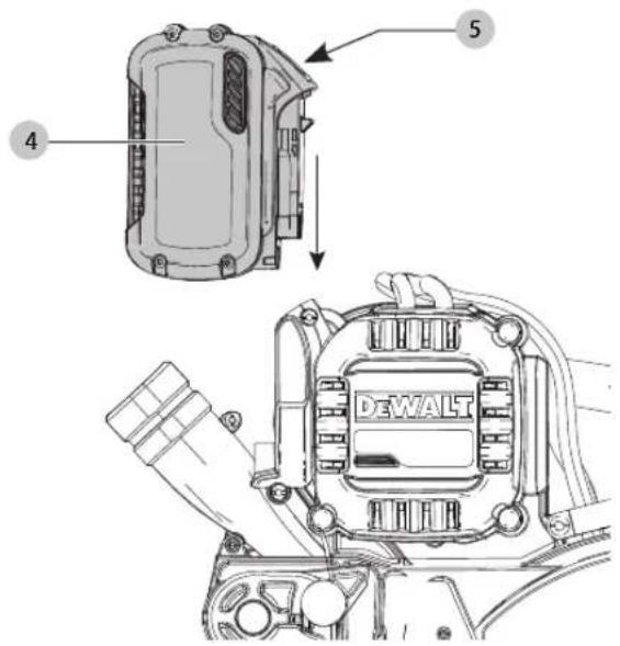
text_image
4 5 DEWALTFig. C
text_image
39 68Fig. D
text_image
40 36Fig. E
natural_image
Technical line drawing of a mechanical lever system with tripod supports and a labeled component (no text or symbols present)Fig. F
text_image
42Fig. G
natural_image
Line drawing of a person operating a robotic device inside an open cardboard box, with legs standing below (no text or symbols)Fig. H1
natural_image
Technical diagram of a mechanical assembly with labeled component (1), showing internal components and no readable text or symbols.Fig. H2 Fig. H3
text_image
Technical diagram of a mechanical assembly with numbered parts labeled 1, 31, and 43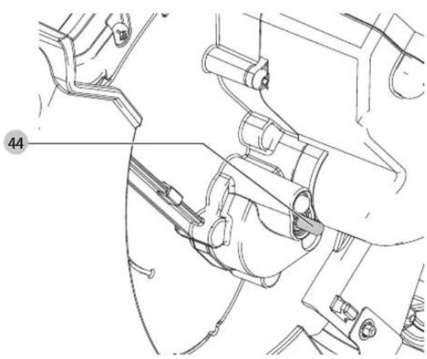
natural_image
Technical line drawing of mechanical components with no visible text or symbolsFig. H4 Fig. I
text_image
45 43 31 46 48 47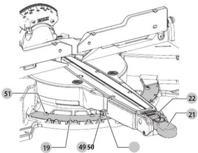
text_image
51 22 21 19 49 50
Fig. O2

natural_image
Diagram of a mechanical device with a diagonal line indicating prohibition (no text or symbols present)Fig. P
natural_image
Technical line drawing of a mechanical assembly with gears and components (no text or symbols)Fig. Q
natural_image
Technical diagram showing a mechanical component with a prohibition symbol (no text or labels present)Fig. R
natural_image
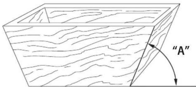
Line drawing of a square wooden crate with visible grain patterns (no text or symbols)Fig. S
1
natural_image
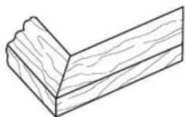
Line drawing of a wooden L-shaped bracket with visible grain patterns (no text or symbols)Fig. T
text_image
"A"2
natural_image
Line drawing of a wooden plank with visible grain patterns (no text or symbols)natural_image
Technical diagram of a mechanical device with a circular prohibition symbol (no text or labels)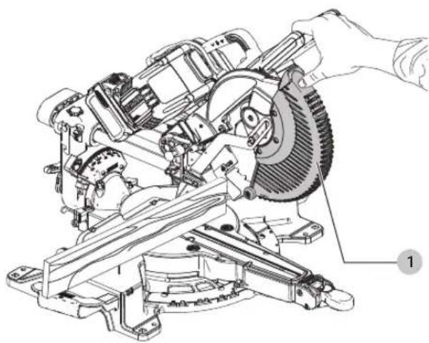
natural_image
Technical line drawing of a mechanical assembly with a hand operating a cutting tool (no text or symbols present)Fig. Z
text_image
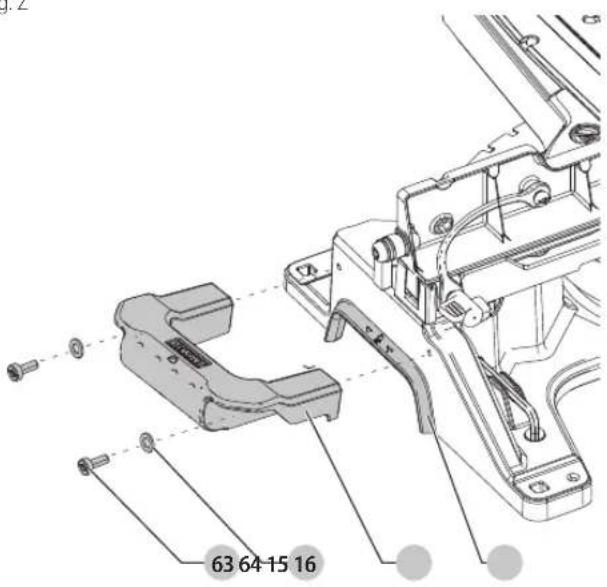
63 64-15 16Fig. AA
text_image
65 66 67GERINGSSAV
DCS727
Tillykke!
At some extreme angles, the right side fence might have to be removed.
You have chosen a DFWALT tool. Years of experience, thorough product development and innovation make DFWALT one of the most reliable partners for professional power tool users.
Technical Data
| DCS727 | ||
| Voltage V | ac | 54 |
| Type 1 | ||
| Battery type Li-Ion | ||
| Blade diameter | mm 250 | |
| Blade bore | mm 30 | |
| Blade body thickness | mm 1.75 | |
| Max. kerf thickness | mm 3.0 | |
| Max. blade speed | min^-1 | 4300 |
| Max. cross-cut capacity 90° | mm 305 | |
| Max. mitre capacity 45° | mm 215 | |
| Max. depth of cut 90° | mm 90 | |
| Max. depth of bevel cross-cut 45° | mm 50 | |
| Mitre (max. positions) | left 50°right 60° | |
| Bevel (max. positions) | left 49°right 49° | |
| 0° mitre | ||
| Baseboard max. height 150 mm | mm 28 | |
| Resulting width at max. height 90 mm | mm 290 | |
| Resulting height at max. width 305 mm | mm 77 | |
| 45° mitre left | ||
| Resulting width at max. height 90 mm | mm 200 | |
| Resulting height at max. width 210 mm | mm 77 | |
| 45° mitre right | ||
| Resulting width at max. height 90 mm | mm 200 | |
| Resulting height at max. width 210 mm | mm 77 | |
| 45° bevel left | ||
| Resulting width at max. height 60 mm | mm 290 | |
| Resulting height at max. width 305 mm | mm 50 | |
| 45° bevel right | ||
| Resulting width at max. height 28 mm | mm 290 | |
| Resulting height at max. width 305 mm | mm 20 | |
| Automatic blade brake time | s < 4 | |
| Weight (without battery pack) kg 20.5 | ||
| Noise values and/or vibration values (triax vector sum) according to EN62841-3-9: | ||
| L_PA (emission sound pressure level) dB(A) 100.3 | ||
| L_WA (sound power level) | dB(A) 111.7 | |
| K(uncertainty for the given sound level) | dB(A) | 3 |
The vibration and/or noise emission level given in this information sheet has been measured in accordance with a standardised test given in EN62841 and may be used to compare one tool with another. It may be used for a preliminary assessment of exposure.
WARNING: The declared vibration and/or noise emission level represents the main applications of the tool. However if the tool is used for different applications, with different accessories or poorly maintained, the vibration and/or noise emission may differ. This may significantly increase the exposure level over the total working period.
An estimation of the level of exposure to vibration and/or noise should also take into account the times when the tool is switched off or when it is running but not actually doing the job. This may significantly reduce the exposure level over the total working period.
Identify additional safety measures to protect the operator from the effects of vibration and/or noise such as: maintain the tool and the accessories, keep the hands warm (relevant for vibration), organisation of work patterns.
EC-Declaration of Conformity
Machinery Directive and Radio Equipment Directive

Mitre Saw
DCS727
DEWALT declares that these products described under Technical Data are in compliance with:
2006/42/EC, EN62841-1:2015/AC:2015; EN62841-3-9:2015/AC:2016-09.
These products also comply with Directive 2014/53/EU, 2014/30/EU and 2011/65/EU. For more information, please contact DEWALT at the following address or refer to the back of the manual.
The undersigned is responsible for compilation of the technical file and makes this declaration on behalf of DEWALT.

text_image
Mr. RergelMarkus Rompel
Vice-President Engineering, PTE-Europa
D-65510, Idstein, Germany
14.06.2019

WARNING: To reduce the risk of injury, read the instruction manual.
Definitions: Safety Guidelines
The definitions below describe the level of severity for each signal word. Please read the manual and pay attention to these symbols.
DAJIGER: Indicates an imminently hazardous situation which, if not evolved, will result in death or serious injury.
WARNING: Indicates a potentially hazardous situation which, if not evolved, could result in death or serious injury.
CAUTION: Indicates a potentially hazardous situation which, if not evolved, may result in minor or moderate injury.
NOTICE: Indicates a practice not related to personal injury which, if not avoided, may result in property damage.
Diabetes risk of electric shock.
Diabetes risk of fire.
| Batteries Chargers/Charge | Times (Minutes) | ||||||||||
| Cat # V | _DC | Ah Weight (kg) | DCB104 | DCB107 | DCB112 | DCB113 | DCB115 | DCB118 | DCB132 | DCB119 | |
| DCB546 | 18/54 | 6.0/2.0 | 1.05 | 60 | 270 | 170 | 140 | 90 | 60 | 90 | |
| DCB547 | 18/54 | 9.0/3.0 | 1.46 | 75* | 420 | 270 | 220 | 135* | 75* | 135* | X |
| DCB548 | 18/54 | 12.0/4.0 | 1.44 | 120 | 540 | 350 | 300 | 180 | 120 | 180 | X |
| DCB181 | 18 | 1.5 | 0.35 | 22 | 70 | 45 | 35 | 22 | 22 | 22 | 45 |
| DCB182 | 18 | 4.0 | 0.61 | 60/40** | 185 | 120 | 100 | 60 | 60/40** | 60 | 120 |
| DCB183/B | 18 | 2.0 | 0.40 | 30 | 90 | 60 | 50 | 30 | 30 | 30 | 60 |
| DCB184/B | 18 | 5.0 | 0.62 | 75/50** | 240 | 150 | 120 | 75 | 75/50** | 75 | 150 |
| DCB185 | 18 | 1.3 | 0.35 | 22 | 60 | 40 | 30 | 22 | 22 | 22 | X |
| DCB187 | 18 | 3.0 | 0.54 | 45 | 140 | 90 | 70 | 45 | 45 | 45 | 90 |
| DCB189 | 18 | 4.0 | 0.54 | 60 | 185 | 120 | 100 | 60 | 60 | 60 | |
*Date code 201811475B or later
**Date code 201536 or later
GENERAL POWER TOOL SAFETY WARNINGS
WARNING: Read all safety warnings, instructions, illustrations and specifications provided with this power tool. Failure to follow all instructions listed below may result in electric shock, fire and/or serious injury.
SAVE ALL WARNINGS AND INSTRUCTIONS FOR FUTURE REFERENCE.
The term "power tool" in the warnings refers to your mains-operated (corded) power tool or battery-operated (cordless) power tool.
1) Work Area Safety
a) Keep work area clean and well lit. Cluttered or dark areas invite accidents.
b) Do not operate power tools in explosive atmospheres, such as in the presence of flammable liquids, gases or dust. Power tools create sparks which may ignite the dust or fumes.
c) Keep children and bystanders away while operating a power tool. Distractions can cause you to lose control.
2) Electrical Safety
a) Power tool plugs must match the outlet. Never modify the plug in any way. Do not use any adapter plugs with earthed (grounded) power tools. Unmodified plugs and matching outlets will reduce risk of electric shock.
b) Avoid body contact with earthed or grounded surfaces, such as pipes, radiators, ranges and refrigerators. There is an increased risk of electric shock if your body is earthed or grounded.
c) Do not expose power tools to rain or wet conditions. Water entering a power tool will increase the risk of electric shock.
d) Do not abuse the cord. Never use the cord for carrying, pulling or unplugging the power tool. Keep cord away from heat, oil, sharp edges or moving parts. Damaged or entangled cords increase the risk of electric shock.
e) When operating a power tool outdoors, use an extension cord suitable for outdoor use. Use of a cord suitable for outdoor use reduces the risk of electric shock.
f) If operating a power tool in a damp location is unavoidable, use a residual current device (RCD) protected supply. Use of an RCD reduces the risk of electric shock.
3) Personal Safety
a) Stay alert, watch what you are doing and use common sense when operating a power tool. Do not use a power tool while you are tired or under the influence of drugs, alcohol or medication. A moment of inattention while operating power tools may result in serious personal injury.
b) Use personal protective equipment. Always wear eye protection. Protective equipment such as a dust mask, non-skid
safety shoes, hard hat or hearing protection used for appropriate conditions will reduce personal injuries.
c) Prevent unintentional starting. Ensure the switch is in the off-position before connecting to power source and/or battery pack, picking up or carrying the tool. Carrying power tools with your finger on the switch or energising power tools that have the switch on invites accidents.
d) Remove any adjusting key or wrench before turning the power tool on. A wrench or a key left attached to a rotating part of the power tool may result in personal injury.
e) Do not overreach. Keep proper footing and balance at all times. This enables better control of the power tool in unexpected situations.
f) Dress properly. Do not wear loose clothing or jewellery. Keep your hair and clothing away from moving parts. Loose clothes, jewellery or long hair can be caught in moving parts.
g) If devices are provided for the connection of dust extraction and collection facilities, ensure these are connected and properly used. Use of dust collection can reduce dust-related hazards.
h) Do not let familiarity gained from frequent use of tools allow you to become complacent and ignore tool safety principles. A careless action can cause severe injury within a fraction of a second.
4) Power Tool Use and Care
a) Do not force the power tool. Use the correct power tool for your application. The correct power tool will do the job better and safer at the rate for which it was designed.
b) Do not use the power tool if the switch does not turn it on and off. Any power tool that cannot be controlled with the switch is dangerous and must be repaired.
c) Disconnect the plug from the power source and/or remove the battery pack, if detachable, from the power tool before making any adjustments, changing accessories, or storing power tools. Such preventive safety measures reduce the risk of starting the power tool accidentally.
d) Store idle power tools out of the reach of children and do not allow persons unfamiliar with the power tool or these instructions to operate the power tool. Power tools are dangerous in the hands of untrained users.
e) Maintain power tools and accessories. Check for misalignment or binding of moving parts, breakage of parts and any other condition that may affect the power tool's operation. If damaged, have the power tool repaired before use. Many accidents are caused by poorly maintained power tools.
f) Keep cutting tools sharp and clean. Properly maintained cutting tools with sharp cutting edges are less likely to bind and are easier to control.
g) Use the power tool, accessories and tool bits etc. in accordance with these instructions, taking into account the working
EnGLIsh
conditions and the work to be performed. Use of the power tool for operations different from those intended could result in a hazardous situation.
h) Keep handles and grasping surfaces dry, clean and free from oil and grease. Slippery handles and grasping surfaces do not allow for safe handling and control of the tool in unexpected situations.
5) Battery Tool Use and Care
a) Recharge only with the charger specified by the manufacturer. A charger that is suitable for one type of battery pack may create a risk of fire when used with another battery pack.
b) Use power tools only with specifically designated battery packs. Use of any other battery packs may create a risk of injury and fire.
c) When battery pack is not in use, keep it away from other metal objects, like paper clips, coins, keys, nails, screws or other small metal objects, that can make a connection from one terminal to another. Shorting the battery terminals together may cause burns or a fire.
d) Under abusive conditions, liquid may be ejected from the battery; avoid contact. If contact accidentally occurs, flush with water. If liquid contacts eyes, additionally seek medical help. Liquid ejected from the battery may cause irritation or burns.
e) Do not use a battery pack or tool that is damaged or modified. Damaged or modified batteries may exhibit unpredictable behaviour resulting in fire, explosion or risk of injury.
f) Do not expose a battery pack or tool to fire or excessive temperature. Exposure to fire or temperature above 130 °C may cause explosion.
g) Follow all charging instructions and do not charge the battery pack or tool outside the temperature range specified in the instructions. Charging improperly or at temperatures outside the specified range may damage the battery and increase the risk of fire.
6) Service
a) Have your power tool serviced by a qualified repair person using only identical replacement parts. This will ensure that the safety of the power tool is maintained.
b) Never service damaged battery packs. Service of battery packs should only be performed by the manufacturer or authorized service providers.
Safety Instructions for Mitre Saws
a) Mitre saws are intended to cut wood or wood-like products, they cannot be used with abrasive cut-off wheels for cutting ferrous material such as bars, rods, studs, etc. Abrasive dust causes moving parts such as the lower guard to jam. Sparks from abrasive cutting will burn the lower guard, the kerf insert and other plastic parts.
b) Use clamps to support the workpiece whenever possible. If supporting the workpiece by hand, you must always keep your hand at least 100 mm from either side of the saw blade. Do not use this saw to cut pieces that are too small to be securely clamped or held by hand. If your hand is placed too close to the saw blade, there is an increased risk of injury from blade contact.
c) The workpiece must be stationary and clamped or held against both the fence and the table. Do not feed the workpiece into the blade or cut "freehand" in any way. Unrestrained or moving workpieces could be thrown at high speeds, causing injury.
d) Push the saw through the workpiece. Do not pull the saw through the workpiece. To make a cut, raise the saw head and pull it out over the workpiece without cutting, start the motor, press the saw head down and push the saw through the workpiece. Cutting on the pull stroke is likely to cause the saw blade to climb on top of the workpiece and violently throw the blade assembly towards the operator.
e) Never cross your hand over the intended line of cutting either in front or behind the saw blade. Supporting the workpiece "cross
handed" i.e. holding the workpiece to the right of the saw blade with your left hand or vice versa is very dangerous.
f) Do not reach behind the fence with either hand closer than 100 mm from either side of the saw blade, to remove wood scraps, or for any other reason while the blade is spinning. The proximity of the spinning saw blade to your hand may not be obvious and you may be seriously injured.
g) Inspect your workpiece before cutting. If the workpiece is bowed or warped, clamp it with the outside bowed face toward the fence. Always make certain that there is no gap between the workpiece, fence and table along the line of the cut. Bent or warped workpieces can twist or shift and may cause binding on the spinning saw blade while cutting. There should be no nails or foreign objects in the workpiece.
h) Do not use the saw until the table is clear of all tools, wood scraps, etc., except for the workpiece. Small debris or loose pieces of wood or other objects that contact the revolving blade can be thrown with high speed.
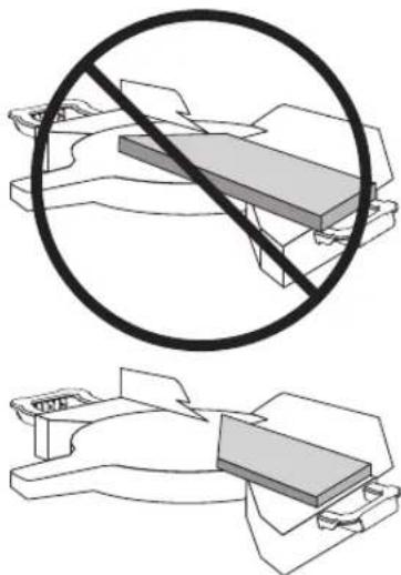
i) Cut only one workpiece at a time. Stacked multiple workpieces cannot be adequately clamped or braced and may bind on the blade or shift during cutting.
j) Ensure the mitre saw is mounted or placed on a level, firm work surface before use. A level and firm work surface reduces the risk of the mitre saw becoming unstable.
k) Plan your work. Every time you change the bevel or mitre angle setting, make sure the adjustable fence is set correctly to support the workpiece and will not interfere with the blade or the guarding system. Without turning the tool "ON" and with no workpiece on the table, move the saw blade through a complete simulated cut to assure there will be no interference or danger of cutting the fence.
1) Provide adequate support such as table extensions, saw horses, etc. for a workpiece that is wider or longer than the table top. Workpieces longer or wider than the mitre saw table can tip if not securely supported. If the cut-off piece or workpiece tips, it can lift the lower guard or be thrown by the spinning blade.
m) Do not use another person as a substitute for a table extension or as additional support. Unstable support for the workpiece can cause the blade to bind or the workpiece to shift during the cutting operation pulling you and the helper into the spinning blade.
n) The cut-off piece must not be jammed or pressed by any means against the spinning saw blade. If confined, i.e. using length stops, the cut-off piece could get wedged against the blade and thrown violently.
a) Always use a clamp or a fixture designed to properly support round material such as rods or tubing. Rods have a tendency to roll while being cut, causing the blade to "bite" and pull the work with your hand into the blade.
p) Let the blade reach full speed before contacting the workpiece. This will reduce the risk of the workpiece being thrown.
q) If the workpiece or blade becomes jammed, turn the mitre saw off. Wait for all moving parts to stop and disconnect the plug from the power source and/or remove the battery pack. Then work to free the jammed material. Continued sawing with a jammed workpiece could cause loss of control or damage to the mitre saw.
r) After finishing the cut, release the switch, hold the saw head down and wait for the blade to stop before removing the cut-off piece. Reaching with your hand near the coasting blade is dangerous.
s) Hold the handle firmly when making an incomplete cut or when releasing the switch before the saw head is completely in the down position. The braking action of the saw may cause the saw head to be suddenly pulled downward, causing a risk of injury.
Additional Safety Rules for Mitre Saws
WARNING: Do not connect to the mains power supply into the unit until complete instructions are read and understood.
- DO NOT OPERATE THIS MACHINE until it is completely assembled and installed according to the instructions. A machine incorrectly assembled can cause serious injury.
- OBTAIN ADVICE from your supervisor, instructor, or another qualified person if you are not thoroughly familiar with the operation of this machine. Knowledge is safety.
• MAKE CERTAIN the blade rotates in the correct direction. The teeth on the blade should point in the direction of rotation as marked on the saw.
- TIGHTEN ALL CLAMP HANDLES, knobs and levers prior to operation. Loose clamps can cause parts or the workpiece to be thrown at high speeds.
- BE SURE all blade and blade clamps are clean, recessed sides of blade clamps are against blade and arbour screw is tightened securely. Loose or improper blade clamping may result in damage to the saw and possible personal injury.
- DO NOT OPERATE ON ANYTHING OTHER THAN THE DESIGNATED VOLTAGE for the saw. Overheating, damage to the tool and personal injury may occur.
- DO NOT WEDGE ANYTHING AGAINST THE FAN to hold the motor shaft. Damage to tool and possible personal injury may occur.
- NEVER CUT METALS or masonry. Either of these can cause the carbide tips to fly off the blade at high speeds causing serious injury.
- NEVER HAVE ANY PART OF YOUR BODY IN LINE WITH THE PATH OF THE SAW BLADE. Personal injury will occur.
- NEVER APPLY BLADE LUBRICANT TO A RUNNING BLADE. Applying lubricant could cause your hand to move into the blade resulting in serious injury.
• DO NOT place either hand in the blade area when the saw is connected to the power source. Inadvertent blade activation may result in serious injury.
- NEVER REACH AROUND OR BEHIND THE SAW BLADE. A blade can cause serious injury.
• DO NOT REACH UNDERNEATH THE SAW unless it is unplugged and turned off. Contact with saw blade may cause personal injury.
- SECURE THE MACHINE TO A STABLE SUPPORTING SURFACE. Vibration can possibly cause the machine to slide, walk, or tip over, causing serious injury.
- USE ONLY CROSSCUT SAW BLADES recommended for mitre saws. For best results, do not use carbide tipped blades with hook angles in excess of 7 degrees. Do not use blades with deep gullets. These can deflect and contact the guard, and can cause damage to the machine and/or serious injury.
- USE ONLY BLADES OF THE CORRECT SIZE AND TYPE specified for this tool to prevent damage to the machine and/or serious injury (complying with EN847-1).
• INSPECT BLADE FOR CRACKS or other damage prior to operation. A cracked or damaged blade can come apart and pieces can be thrown at high speeds, causing serious injury. Replace cracked or damaged blades immediately. Observe the maximum speed marked on the saw blade.
- THE MAXIMUM SPEED OF THE SAW BLADE shall always be greater than or at least equal to the speed marked on the rating plate of the tool.
- THE SAW BLADE DIAMETER must be in accordance with the markings on rating plate of the tool.
- CLEAN THE BLADE AND BLADE CLAMPS prior to operation. Cleaning the blade and blade clamps allows you to check for any damage to the blade or blade clamps. A cracked or damaged blade or blade clamp can come apart and pieces can be thrown at high speeds, causing serious injury.
- DO NOT USE WARPED BLADES. Check to see if the blade runs true and is free from vibration. A vibrating blade can cause damage to the machine and/or serious injury.
• DO NOT use lubricants or cleaners (particularly spray or aerosol) in the vicinity of the plastic guard. The polycarbonate material used in the guard is subject to attack by certain chemicals.
- KEEP GUARD IN PLACE and in working order.
- ALWAYS USE THE KERF PLATE AND REPLACE THIS PLATE WHEN DAMAGED. Small chip accumulation under the saw may interfere with the saw blade or may cause instability of workpiece when cutting.
- USE ONLY BLADE CLAMPS SPECIFIED FOR THIS TOOL to prevent damage to the machine and/or serious injury.
• MAKE SURE to use the correct saw blade for the material to be cut.
- CLEAN THE MOTOR AIR SLOTS of chips and sawdust. Clogged motor air slots can cause the machine to overheat, damaging the machine and possibly causing a short which could cause serious injury.
- NEVER LOCK THE SWITCH IN THE "ON" POSITION. Severe personal injury may result.
- NEVER STAND ON TOOL. Serious injury could occur if the tool is tipped or if the cutting tool is unintentionally contacted.
WARNING: Cutting plastics, sap coated wood, and other materials may cause melted material to accumulate on the blade tips and the body of the saw blade, increasing the risk of blade overheating and binding while cutting.
WARNING: Always wear proper personal hearing protection. Use some conditions and duration of use, noise from this product may contribute to hearing loss. Be aware of the following factors influencing exposure to noise:
- Use saw blades designed to reduce the emitted noise, - Use only well sharpened saw blades, and - Use specifically designed noise-reduction saw blades.
WARNING: ALWAYS use safety glasses. Everyday eyeglasses are NOT safe glasses. Also use face or dust mask if cutting operation is dusty.
WARNING: Use of this tool can generate and/or disperse dust, which may cause serious and permanent respiratory or other injury.
WARNING: Some dust created by power sanding, sawing, grinding, and other construction activities contains chemicals known to cause cancer, birth defects or other reproductive harm. Some examples of these chemicals are:
- lead from lead-based paints, - crystalline silica from bricks and cement and other masonry products, and - arsenic and chromium from chemically-treated lumber.
Your risk from these exposures varies, depending on how often you do this type of work. To reduce your exposure to these chemicals: work in a well ventilated area, and work with approved safety equipment, such as those dust masks that are specially designed to filter out microscopic particles.
- Avoid prolonged contact with dust from power sanding, sawing, grinding, drilling, and other construction activities. Wear protective clothing and wash exposed areas with soap and water. Allowing dust to get into your mouth, eyes, or lay on the skin may promote absorption of harmful chemicals.
WARNING: Use of this tool can generate and/or disperse dust, which may cause serious and permanent respiratory or other injury. Always use approved respiratory protection appropriate for the dust exposure.
Residual Risks
The following risks are inherent to the use of saws:
• Injuries caused by touching the rotating parts.
In spite of the application of the relevant safety regulations and the implementation of safety devices, certain residual risks cannot be avoided. These are:
- Impairment of hearing.
EnGLIsh
- Risk of accidents caused by the uncovered parts of the rotating saw blade.
• Risk of injury when changing the blade. - Risk of squeezing fingers when opening the guards.
• Health hazards caused by breathing dust developed when sawing wood, especially oak, beech and MDF.
The following factors increase the risk of breathing problems: - No dust extractor connected when sawing wood.
- Insufficient dust extraction caused by uncleaned exhaust filters.
SAVE THESE INSTRUCTIONS
Chargers
DiWALT chargers require no adjustment and are designed to be as easy as possible to operate.
Electrical Safety
The electric motor has been designed for one voltage only. Always check that the battery pack voltage corresponds to the voltage on the rating plate. Also make sure that the voltage of your charger corresponds to that of your mains.

Your DEWALT charger is double insulated in accordance with EN60335; therefore no earth wire is required.
If the supply cord is damaged, it must be replaced only by DEWALT or an authorised service organisation.
Mains Plug Replacement (U.K. & Ireland Only)
If a new mains plug needs to be fitted:
- Safely dispose of the old plug.
- Connect the brown lead to the live terminal in the plug.
- Connect the blue lead to the neutral terminal.

ING: No connection is to be made to the earth terminal.
Follow the fitting instructions supplied with good quality plugs. Recommended fuse: 3 A.
Using an Extension Cable
An extension cord should not be used unless absolutely necessary. Use an approved extension cable suitable for the power input of your charger (see Technical Data). The minimum conductor size is 1 mm ^2 ; the maximum length is 30 m.
When using a cable reel, always unwind the cable completely.
Important Safety Instructions for All Battery Chargers
SAVE THESE INSTRUCTIONS: This manual contains important safety and operating instructions for compatible battery chargers (refer to Technical Data).
- Before using charger, read all instructions and cautionary markings on charger, battery pack, and product using battery pack.

NING: Shock hazard. Do not allow any liquid to get inside her. Electric shock may result.

ING: We recommend the use of a residual current device with a current rating of 30mA or less.

ON: Burn hazard. To reduce the risk of injury, charge only T rechargeable batteries. Other types of batteries may burst g personal injury and damage.

ON: Children should be supervised to ensure that they do not with the appliance.
NOTICE: Under certain conditions, with the charger plugged into the power supply, the exposed charging contacts inside the charger can be shorted by foreign material. Foreign materials of a conductive nature such as, but not limited to, steel wool, aluminum foil or any buildup of metallic particles should be kept away from charger cavities. Always unplug the charger from the power supply when there is no battery pack in the cavity. Unplug charger before attempting to clean
- DO NOT attempt to charge the battery pack with any chargers other than the ones in this manual. The charger and battery pack are specifically designed to work together.
• These chargers are not intended for any uses other than charging DeWALT rechargeable batteries. Any other uses may result in risk of fire, electric shock or electrocution. - Do not expose charger to rain or snow.
- Pull by plug rather than cord when disconnecting charger. This will reduce risk of damage to electric plug and cord.
- Make sure that cord is located so that it will not be stepped on, tripped over, or otherwise subjected to damage or stress.
- Do not use an extension cord unless it is absolutely necessary. Use of improper extension cord could result in risk of fire, electric shock, or electrocution.
- Do not place any object on top of charger or place the charger on a soft surface that might block the ventilation slots and result in excessive internal heat. Place the charger in a position away from any heat source. The charger is ventilated through slots in the top and the bottom of the housing.
- Do not operate charger with damaged cord or plug—have them replaced immediately.
- Do not operate charger if it has received a sharp blow, been dropped, or otherwise damaged in any way. Take it to an authorised service centre.
- Do not disassemble charger; take it to an authorised service centre when service or repair is required. Incorrect reassembly may result in a risk of electric shock, electrocution or fire.
- In case of damaged power supply cord the supply cord must be replaced immediately by the manufacturer, its service agent or similar qualified person to prevent any hazard.
- Disconnect the charger from the outlet before attempting any cleaning. This will reduce the risk of electric shock. Removing the battery pack will not reduce this risk.
- NEVER attempt to connect two chargers together.
- The charger is designed to operate on standard 230V household electrical power. Do not attempt to use it on any other voltage. This does not apply to the vehicular charger.
Charging a Battery (Fig. B)
- Plug the charger into an appropriate outlet before inserting battery pack.
- Insert the battery pack 4 into the charger, making sure the battery pack is fully seated in the charger. The red (charging) light will blink repeatedly indicating that the charging process has started.
- The completion of charge will be indicated by the red light remaining ON continuously. The battery pack is fully charged and may be used at this time or left in the charger. To remove the battery pack from the charger, push the battery release button 5 on the battery pack.
NOTE: To ensure maximum performance and life of lithium-ion battery packs, charge the battery pack fully before first use.
Charger Operation
Refer to the indicators below for the charge status of the battery pack.
| Charge Indicators | |
| Charging | — — — — — |
| Fully Charged | — — — — — |
| Hot/Cold Pack Delay* | — — — — — |
* The red light will continue to blink, but a yellow indicator light will be illuminated during this operation. Once the battery pack has reached an appropriate temperature, the yellow light will turn off and the charger will resume the charging procedure.
The compatible charger(s) will not charge a faulty battery pack. The charger will indicate faulty battery by refusing to light.
NOTE: This could also mean a problem with a charger.
If the charger indicates a problem, take the charger and battery pack to be tested at an authorised service centre.
Hot/Cold Pack Delay
When the charger detects a battery pack that is too hot or too cold, it automatically starts a Hot/Cold Pack Delay, suspending charging until the battery pack has reached an appropriate temperature. The charger then automatically switches to the pack charging mode. This feature ensures maximum battery pack life.
A cold battery pack will charge at a slower rate than a warm battery pack. The battery pack will charge at that slower rate throughout the entire charging cycle and will not return to maximum charge rate even if the battery pack warms.
The DCB118 charger is equipped with an internal fan designed to cool the battery pack. The fan will turn on automatically when the battery pack needs to be cooled. Never operate the charger if the fan does not operate properly or if ventilation slots are blocked. Do not permit foreign objects to enter the interior of the charger.
Electronic Protection System
XR Li-Ion tools are designed with an Electronic Protection System that will protect the battery pack against overloading, overheating or deep discharge.
The tool will automatically turn off if the Electronic Protection System engages. If this occurs, place the lithium-ion battery pack on the charger until it is fully charged.
Wall Mounting
These chargers are designed to be wall mountable or to sit upright on a table or work surface. If wall mounting, locate the charger within reach of an electrical outlet, and away from a corner or other obstructions which may impede air flow. Use the back of the charger as a template for the location of the mounting screws on the wall. Mount the charger securely using drywall screws (purchased separately) at least 25.4 mm long with a screw head diameter of 7–9 mm, screwed into wood to an optimal depth leaving approximately 5.5 mm of the screw exposed. Align the slots on the back of the charger with the exposed screws and fully engage them in the slots.
Charger Cleaning Instructions
WARNING: Shock hazard. Disconnect the charger from the AC outlet before cleaning. Dirt and grease may be removed from the exterior of the charger using a cloth or soft non-metallic brush. Do not use water or any cleaning solutions. Never let any liquid get inside the tool; never immerse any part of the tool into a liquid.
Battery Packs
Important Safety Instructions for All Battery Packs
When ordering replacement battery packs, be sure to include catalogue number and voltage.
The battery pack is not fully charged out of the carton. Before using the battery pack and charger, read the safety instructions below. Then follow charging procedures outlined.
READ ALL INSTRUCTIONS
- Do not charge or use battery in explosive atmospheres, such as in the presence of flammable liquids, gases or dust. Inserting or removing the battery from the charger may ignite the dust or fumes.
- Never force battery pack into charger. Do not modify battery pack in any way to fit into a non-compatible charger as battery pack may rupture causing serious personal injury.
- Charge the battery packs only in DEWALT chargers.
• DO NOT splash or immerse in water or other liquids. - Do not store or use the tool and battery pack in locations where the temperature may fall below 4 °C (34 °F) (such as outside sheds or
metal buildings in winter), or reach or exceed 40 °C (104 °F) (such as outside sheds or metal buildings in summer).
- Do not incinerate the battery pack even if it is severely damaged or is completely worn out. The battery pack can explode in a fire. Toxic fumes and materials are created when lithium-ion battery packs are burned.
- If battery contents come into contact with the skin, immediately wash area with mild soap and water. If battery liquid gets into the eye, rinse water over the open eye for 15 minutes or until irritation ceases. If medical attention is needed, the battery electrolyte is composed of a mixture of liquid organic carbonates and lithium salts.
- Contents of opened battery cells may cause respiratory irritation. Provide fresh air. If symptoms persist, seek medical attention.
WARNING: Burn hazard. Battery liquid may be flammable if exposed to spark or flame.
WARNING: Never attempt to open the battery pack for any reason. If battery pack case is cracked or damaged, do not insert into charger. Do not crush, drop or damage battery pack. Do not use a battery pack or charger that has received a sharp blow, been dropped, run over or damaged in any way (i.e., pierced with a nail, hit with a hammer, stepped on). Electric shock or electrocution may result. Damaged battery packs should be returned to service centre for recycling.
WARNING: Fire hazard. Do not store or carry the battery pack so metal objects can contact exposed battery terminals. For example, do not place the battery pack in aprons, pockets, tool boxes, product kit boxes, drawers, etc., with loose nails, screws, keys, etc.
CAUTION: When not in use, place tool on its side on a stable surface where it will not cause a tripping or falling hazard. Some tools with large battery packs will stand upright on the battery pack but may be easily knocked over.
Transportation
WARNING: Fire hazard. Transporting batteries can possibly cause the battery terminals inadvertently come in contact with conductive materials. When transporting batteries, make sure that the battery terminals are protected and well insulated from materials that could contact them and cause a short circuit.
NOTE: Lithium-ion batteries should not be put in checked baggage.
DEWALT batteries comply with all applicable shipping regulations as prescribed by industry and legal standards which include UN Recommendations on the Transport of Dangerous Goods; International Air Transport Association (IATA) Dangerous Goods Regulations, International Maritime Dangerous Goods (IMDG) Regulations, and the European Agreement Concerning The International Carriage of Dangerous Goods by Road (ADR). Lithium-ion cells and batteries have been tested to section 38.3 of the UN Recommendations on the Transport of Dangerous Goods Manual of Tests and Criteria.
In most instances, shipping a DEWALT battery pack will be excepted from being classified as a fully regulated Class 9 Hazardous Material. In general, only shipments containing a lithium-ion battery with an energy rating greater than 100 Watt Hours (Wh) will require being shipped as fully regulated Class 9. All lithium-ion batteries have the Watt Hour rating marked on the pack. Furthermore, due to regulation complexities, DEWALT does not recommend air shipping lithium-ion battery packs alone regardless of Watt Hour rating. Shipments of tools with batteries (combo kits) can be air shipped as excepted if the Watt Hour rating of the battery pack is no greater than 100 Whr.
Regardless of whether a shipment is considered excepted or fully regulated, it is the shipper's responsibility to consult the latest regulations for packaging, labeling/marking and documentation requirements.
The information provided in this section of the manual is provided in good faith and believed to be accurate at the time the document was created. However, no warranty, expressed or implied, is given. It is the buyer's responsibility to ensure that its activities comply with the applicable regulations.
Transporting the FLEXVOLT™ Battery
The DEWALT FLEXVOLT ^™ battery has two modes: Use and Transport.
Use Mode: When the FLEXVOLT™ battery stands alone or is in a DEWALT 18V product, it will operate as an 18V battery. When the FLEXVOLT™ battery is in a 54V or a 108V (two 54V batteries) product, it will operate as a 54V battery.
Transport Mode: When the cap is attached to the FLEXVOLT™ battery, the battery is in Transport mode. Keep the cap for shipping.
When in Transport mode, strings of cells are electrically disconnected within the pack resulting in 3 batteries with a lower Watt hour (Wh) rating as compared to 1 battery
with a higher Watt hour rating. This increased quantity of 3 batteries with the lower Watt hour rating can exempt the pack from certain shipping regulations that are imposed upon the higher Watt hour batteries.
For example, the Transport Wh rating might indicate 3 x 36 Wh, meaning 3 batteries of 36 Wh each. The Use Wh rating might indicate 108 Wh (1 battery implied).
Example of Use and Transport Label Marking

Use: 108 Wh

Transport: 3x36 Wh
Storage Recommendations
- The best storage place is one that is cool and dry away from direct sunlight and excess heat or cold. For optimum battery performance and life, store battery packs at room temperature when not in use.
- For long storage, it is recommended to store a fully charged battery pack in a cool, dry place out of the charger for optimal results.
NOTE: Battery packs should not be stored completely depleted of charge. The battery pack will need to be recharged before use.
Labels on Charger and Battery Pack
In addition to the pictographs used in this manual, the labels on the charger and the battery pack may show the following pictographs:

Read instruction manual before use.


See Technical Data for charging time.
Do not probe with conductive objects.
Do not charge damaged battery packs.
Do not expose to water.
Have defective cords replaced immediately.
Charge only between 4 °C and 40 °C.
Only for indoor use.
Discard the battery pack with due care for the environment.
Charge DEWALT battery packs only with designated DEWALT chargers. Charging battery packs other than the designated DEWALT batteries with a DEWALT charger may make them burst or lead to other dangerous situations.

Do not incinerate the battery pack.

USE (without transport cap). Example: Wh rating indicates 108 Wh (1 battery with 108 Wh).

TRANSPORT (with built-in transport cap). Example: Wh rating indicates 3 x 36 Wh (3 batteries of 36 Wh).
Battery Type
The DCS727 operates on a 54 volt battery pack.
These battery packs may be used: DCB546, DCB547, DCB548. Refer to
Technical Data for more information.
Package Contents
The package contains:
1 Assembled mitre saw
1 Blade wrench (assembled on the saw)
1 Saw blade (assembled on the saw)
1 Material clamp
2 Base extensions
2 Screws
2 Washers
1 Li-ion battery pack (C1, D1, L1, M1, P1, S1, T1, X1, Y1 models)
2 Li-ion battery packs (C2, D2, L2, M2, P2, S2, T2, X2, Y2 models)
3 Li-ion battery packs (C3, D3, L3, M3, P3, S3, T3, X3, Y3 models)
1 Instruction manual
NOTE: Battery packs, chargers and kitboxes are not included with N models. Battery packs and chargers are not included with NT models.
- Check for damage to the tool, parts or accessories which may have occurred during transport.
• Take the time to thoroughly read and understand this manual prior to operation.
Markings on Tool
The following pictograms are shown on the tool:

Read instruction manual before use.

Wear ear protection.

Wear eye protection.


Visible radiation. Do not stare into light.
Date Code Position (Fig. A)
The date code 8, which also includes the year of manufacture, is printed into the housing.
Example:
2019 XX XX
Year of Manufacture
Description (Fig. A1, A2, C–F)
WARNING: Never modify the personal injury could result.
Fig. A1
1 Lower guard
2 Operating handle
3 Carrying handle
4 Battery
5 Battery release button
6 Rail lock knob
7 Rail set screw adjustment
8 Date code
9 Rails
10 Bevel scale
11 Lock down pin
12 Fence adjustment knob
13 Sliding fence
14 Base fence
15 Base extension/carry handle
16 Hand indentation
17 Table
18 Bench mounting holes
19 Mitre scale
20 Dust duct inlet
21 Mitre lock handle
22 Mitre latch button
23 Kerf plate
Fig. A2
24 Trigger switch
25 Lock-off lever
26 Padlock hole
27 XPS ^TM temporary on switch
28 Wing nut
29 Depth adjustment screw
30 Grooving stop
31 Blade wrench
32 Base
33 Bevel lock knob
34 0° bevel stop
35 Right-hand flip down stop
36 Dust port
37 Belt cover
38 Mitre detent override
Optional accessories
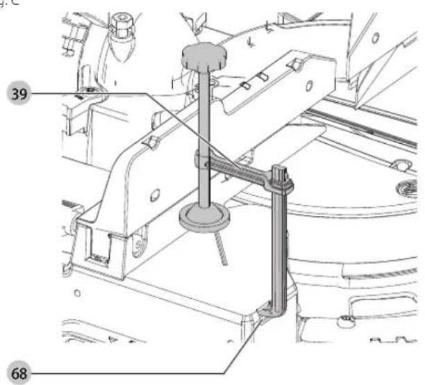
Fig. C
39 DWS5026-XJ Workpiece clamp
Fig. D
40 DW7053-QZ Dustbag
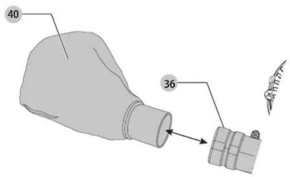
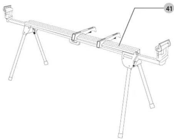
Fig. E
41 DE7023-XJ / DE7033-XJ Leg stand
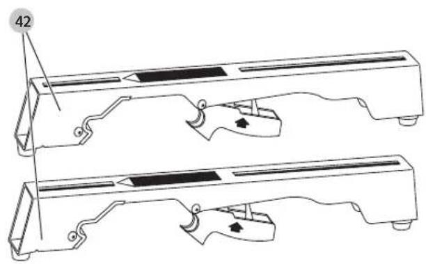
Fig. F
42 DE7025-XJ Clamp brackets
Intended Use
Your DEWALT DCS727 mitre saw has been designed for professional cutting of wood, wood products and plastics. When using the appropriate saw blades, sawing aluminium is also possible. It performs the sawing operations of cross-cutting, bevelling and mitring easily, accurately and safely.
DO NOT use under wet conditions or in the presence of flammable liquids or gases.
This mitre saw is a professional power tool.
DO NOT let children come into contact with the tool. Supervision is required when inexperienced operators use this tool.
- Young children and the infirm. This appliance is not intended for use by young children or infirm persons without supervision.
- This product is not intended for use by persons (including children) suffering from diminished physical, sensory or mental abilities; lack of experience, knowledge or skills unless they are supervised by a person responsible for their safety. Children should never be left alone with this product.
ASSEMBLY AND ADJUSTMENTS
WARNING: To reduce the risk of serious personal injury, turn to off and disconnect battery pack before making any adjustments or removing/installing attachments or accessories.
An accidental start-up can cause injury.
WARNING: Use only DLWALT battery packs and chargers.
Inserting and Removing the Battery Pack from the Tool (Fig. B)
NOTE: Make sure your battery pack 4 is fully charged.
To Install the Battery Pack into the Tool Handle
-
Align the battery pack 4 with the rails inside the tool's handle (Fig. B).
-
Slide it into the handle until the battery pack is firmly seated in the tool and ensure that you hear the lock snap into place.
To Remove the Battery Pack from the Tool
- Press the release button 5 and firmly pull the battery pack out of the tool handle.
- Insert battery pack into the charger as described in the charger section of this manual.
Fuel Gauge Battery Packs (Fig. B)
Some DEWALT battery packs include a fuel gauge which consists of three green LED lights that indicate the level of charge remaining in the battery pack.
To actuate the fuel gauge, press and hold the fuel gauge button 61. A combination of the three green LED lights will illuminate designating the level of charge left. When the level of charge in the battery is below the usable limit, the fuel gauge will not illuminate and the battery will need to be recharged.
NOTE: The fuel gauge is only an indication of the charge left on the battery pack. It does not indicate tool functionality and is subject to variation based on product components, temperature and end-user application.
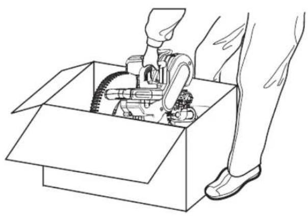
Unpacking (Fig. A1, G)
- Open the box and lift the saw out by the con venient carrying handle 3, as shown in Figure G.
- Place the saw on a smooth, flat surface.
- Release the rail lock knob 6, and push the saw head back to lock it in the rear position.
- Press down lightly on the operating handle 2 and pull out the lock down pin 11.
- Gently release the downward pressure and hold the operating handle, allowing it to rise to its full height.
Bench Mounting (Fig. A1)
Holes 18 are provided in all four feet to facilitate bench mounting. Two different-sized holes are provided to accommodate different sizes of screws. Use either hole; it is not necessary to use both.
Always mount your saw firmly to a stable surface to prevent movement. To enhance the tool's portability, it can be mounted to a piece of 12.7 mm or thicker plywood which can then be clamped to your work support or moved to other job sites and reclamped.
NOTE: If you elect to mount your saw to a piece of plywood, make sure that the mounting screws don't protrude from the bottom of the wood. The plywood must sit flush on the work support. When clamping the saw to any work surface, clamp only on the clamping bosses where the mounting screw holes are located. Clamping at any other point will interfere with the proper operation of the saw.
CAUTION: To prevent binding and inaccuracy, be sure the mounting surface is not warped or otherwise uneven. If the saw rocks on the surface, place a thin piece of material under one saw foot until the saw sits firmly on the mounting surface.
Assembling the Base Extensions (Fig. Z)
WARNING: Base extensions must be assembled to both sides of the saw's base before using the saw.
WARNING: Be sure to adjust the base extensions using the mounting holes so they are level with the saw's base.
- Locate the holes above the hand indentations 16 on the side of the base.
- Using the supplied wrench or a T30 wrench, attach the screw 63 through the washer 64, through the base extension 15, and into the holes on the base.
- Ensure the extension is secure by pulling on the extension to verify no movement.
- Repeat steps 1 through 3 on the other side.
Changing or Installing a New Saw Blade
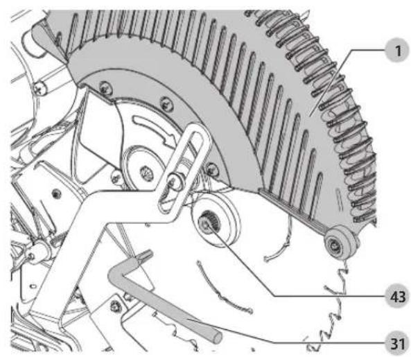
Removing the Blade (Fig. H1–H4)
WARNING: To reduce the risk of injury, wear gloves when handling a new blade.
WARNING: To reduce the risk of serious personal injury, turn to off and disconnect battery pack before making any adjustments or removing/installing attachments or accessories.
An accidental start-up can cause injury.
- Never depress the spindle lock button while the blade is under power or coasting.
-
Do not cut light alloy and ferrous metal (containing iron or steel) or masonry or fibre cement product with this mitre saw.
-
Remove the battery from the saw.
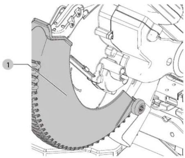
- Raise the arm to the upper position and raise the lower guard 1 as far as possible.
- Depress the spindle lock button 44 while carefully rotating the saw blade by hand until the lock engages.
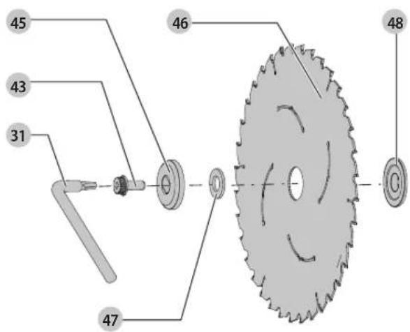
- Keeping the button depressed, use the other hand and the 6 mm wrench provided 31 to loosen the blade screw 43. (Turn clockwise, left-hand threads.)
- Remove the blade screw 43, outer clamp washer 45 and blade 46. The inner washer 48 may be left on the spindle.
- Remove and retain the adaptor ring 47 from the old blade in case it is needed when installing a new blade.
Installing a Blade (Fig. H1–H4)
- Remove the battery from the saw.
- Snap the ring adaptor ring 47 into the hole of the new saw blade if necessary.
- With the arm raised and the lower guard 1 held open, mount the blade onto the shoulder of the inner washer 48, making sure the teeth at the bottom of the blade point toward the back of the saw.
- Assemble the outer clamp washer onto the spindle.
- Install the blade screw and, engaging the spindle lock, tighten the screw firmly with wrench provided (turn counterclockwise, left-hand threads).
WARNING! Be aware the saw blade shall be replaced in the described way only. Only use saw blades as specified under Technical Data; Cat. no.: DT4260 is suggested.
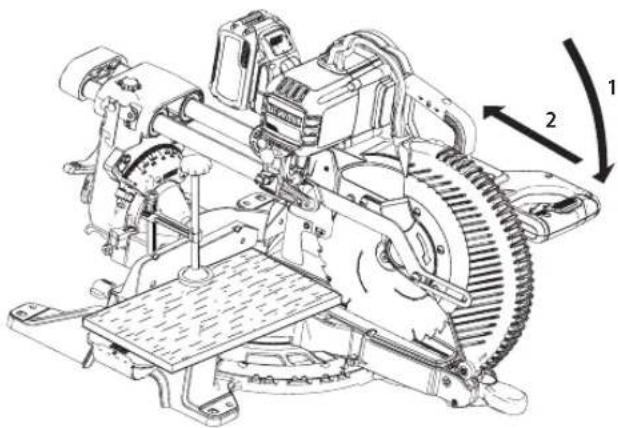
Transporting the Saw (Fig. A1, A2)
WARNING: To reduce the risk of serious personal injury, AFTAYS lock the rail lock knob, mitre lock handle, bevel lock handle, lock down pin and fence adjustment knobs before transporting saw. Never use guards for transporting or lifting up.
In order to conveniently carry the mitre saw, a carrying handle 3 has been included on the top of the saw arm.
- To transport the saw, lower the head and depress the lock down pin 11.
- Lock the rail lock knob with the saw head in the front position, lock the mitre arm in the full left mitre angle, slide the fence 13 completely inward and lock the bevel lock knob 33 with the saw head in the vertical position to make the tool as compact as possible.
• Always use the carrying handle 3 or the base extensions 15.
Features and Controls
WARNING: To reduce the risk of serious personal injury, turn to off and disconnect battery pack before making any adjustments or removing/installing attachments or accessories.
An accidental start-up can cause injury..
Mitre Control (Fig. A2, I)
The mitre lock handle 21 and mitre latch button 22 allow you to mitre your saw to 60° right and 50° left. To mitre the saw, lift the mitre lock handle, push the mitre latch button and set the mitre angle desired on the mitre scale 19. Push down on the mitre lock handle to lock the mitre angle. Override the mitre latch button by unlocking the mitre lock knob and pushing the mitre detent override 38 downward. To exit the override, push the mitre detent override upward.
Bevel Lock Knob (Fig. A2)
The bevel lock allows you to bevel the saw 49° left or right. To adjust the bevel setting, turn the bevel lock knob 33 counterclockwise. The saw head bevels easily to the left or to the right once the 0° bevel override knob is pulled. To tighten, turn the bevel lock knob clockwise.
0° Bevel Override (Fig. A2)
The 0° bevel stop 34 override allows you to bevel the saw to the right past the 0° mark.
When engaged, the saw will automatically stop at 0^ when brought up from the left. To temporarily move past 0^ to the right, pull the bevel lock knob 33. Once the knob is released, the override will be reengaged. The bevel lock knob can be locked out by twisting the knob 180^ .
When at 0^ , the override locks in place. To operate the override, bevel the saw slightly to the left.
45° Bevel Stop Override (Fig. J)
There are two bevel stop override levers, one on each side of the saw. To bevel the saw, left or right, past 45°, push the 45° bevel override lever 55 rearward. When in the rearward position, the saw can bevel past these stops. When the 45° stops are needed, pull the 45° bevel override lever forward.
Crown Bevel Pawls (Fig. J)
When cutting crown molding laying flat, your saw is equipped to accurately and rapidly set a crown stop, left or right (refer to Instructions for Cutting Crown Molding Laying Flat and Using the Compound Features)
The crown bevel pawl 57 can be rotated to contact the crown adjustment screw.
To reverse the crown bevel pawl, remove the retaining screw, the 22.5° bevel pawl 56 and the 30° crown bevel pawl 57. Flip the crown bevel pawl 57 so the 30° text is facing up. Reattach the screw to secure the 22.5° bevel pawl and the crown bevel pawl. The accuracy setting will not be affected.
22.5° Bevel Pawls (Fig. J)
Your saw is equipped to rapidly and accurately set a 22.5° bevel, left or right. The 22.5° bevel pawl 56 can be rotated to contact the crown adjustment screw 54.
Rail Lock Knob (Fig. A1)
The rail lock knob 6 allows you to lock the saw head firmly to keep it from sliding on the rails 9. This is necessary when making certain cuts or when transporting the saw.
Grooving Stop (Fig. A2)
The grooving stop 30 allows the depth of cut of the blade to be limited. The stop is useful for applications such as grooving and tall vertical cuts. Rotate the grooving stop forward and adjust the depth adjustment screw 29 to set the desired depth of cut. To secure the adjustment, tighten the wing nut 28. Rotating the grooving stop to the rear of the saw will bypass the grooving stop feature. If the depth adjustment screw is too tight to loosen by hand, the provided 6 mm blade wrench 31 can be used to loosen the screw.
Lock Down Pin (Fig. A1)
WARNING: The lock down pin should be used only when closing or storing the saw. NEVER use the lock down pin for any cutting operation.
To lock the saw head in the down position, push the saw head down, push the lock down pin 11 in and release the saw head. This will hold the saw head safely down for moving the saw from place to place. To release, press the saw head down and pull the pin out.
Slide Lock Lever (Fig. K, U)
The slide lock lever 62 places the saw in a position to maximize cutting of base moulding when cut vertically as shown in Figure U.
Right-Hand Flip Down Stop (Fig. A1, A2)
The right-hand flip down stop 35 is mounted on the sliding fence 13 and can be rotated backward when not needed. When cutting multiple pieces at the same width, rotate the right-hand flip down stop forward, move out the sliding fence to the required distance from the blade (to be measured by a ruler) and with the wood board facing against the stop make the cut.
Adjustment
Your mitre saw is fully and accurately adjusted at the factory at the time of manufacture. If readjustment due to shipping and handling or any other reason is required, follow the instructions below to adjust your saw. Once made, these adjustments should remain accurate.
Mitre Scale Adjustment (Fig. I, L)
- Unlock the mitre lock handle 21 and swing the mitre arm until the mitre latch button 22 locks it at the 0° mitre position. Do not lock the mitre lock handle.
- Place a square against the saw's fence and blade, as shown. (Do not touch the tips of the blade teeth with the square. To do so will cause an inaccurate measurement.)
- If the saw blade is not exactly perpendicular to the fence, loosen the four screws 51 that hold the mitre scale 19 and move the mitre lock handle and the scale left or right until the blade is perpendicular to the fence, as measured with the square.
- Retighten the four screws. Pay no attention to the reading of the mitre pointer 49 at this time.
Mitre Pointer Adjustment (Fig. I)
- Unlock the mitre lock handle 21 to move the mitre arm to the zero position.
- With the mitre lock handle unlocked, allow the mitre latch to snap into place as you rotate the mitre arm to zero.
- Observe the mitre pointer 49 and mitre scale 19 shown in Figure I. If the pointer does not indicate exactly zero, loosen the mitre pointer screw 50 holding the pointer in place, reposition the pointer and tighten the screw.
Bevel Square to Table Adjustment (Fig. A1, A2, J, M)
- To align the blade square to the table, lock the arm in the down position with the lock down pin 11.
- Place a square against the blade, ensuring the square is not on top of a tooth (Fig. M).
- Loosen the bevel lock knob 33 and ensure the arm is firmly against the 0° bevel stop.
- Rotate the 0^ bevel adjustment screw (59 Fig. J) with the 6 mm blade wrench 31 as necessary so that the blade is at 0^ bevel to the table.
Bevel Pointer Adjustment (Fig. J)
If the bevel pointers 53 do not indicate zero, loosen each screw 52 that holds each bevel pointer in place and move them as necessary. Ensure the 0° bevel is correct and the bevel pointers are set before adjusting any other bevel angle screws.
Bevel Stop 45° Right and Left Adjustment (Fig. A2, J)
To adjust the right 45° bevel stop:
- Slide the fence 13 to the full out position before beveling the saw.
-
Loosen the bevel lock knob 33 and pull the 0° bevel stop 34 to override the 0° bevel stop.
-
When the saw is fully to the right, if the bevel pointer 53 does not indicate exactly 45°, turn the left 45° bevel adjustment screw 58 with the 6 mm blade wrench 31 until the bevel pointer indicates 45°.
To adjust the left 45° bevel stop:
- Slide the fence 13 to the full out position before beveling the saw.
- Loosen the bevel lock knob and tilt the head to the left.
- If the bevel pointer does not indicate exactly 45^ , turn the right 45^ bevel adjustment screw until the bevel pointer reads 45^ .
Adjusting the Bevel Stop to 22.5° (or 30°) (Fig. A2, J)
NOTE: Adjust the bevel angles only after performing the 0° bevel angle and bevel pointer adjustment. Slide the sliding fences to the full out position before starting the 22.5° or 30° bevel adjustment.
To set the left 22.5° bevel angle, flip out the left 22.5° bevel pawl 56. Loosen the bevel lock knob 33 and tilt the head fully to the left. If the bevel pointer 53 does not indicate exactly 22.5°, turn the crown adjustment screw 54 contacting the pawl with a 10 mm wrench until the bevel pointer reads 22.5°.
To adjust the right 22.5° bevel angle, flip out the right 22.5° bevel pawl. Loosen the bevel lock knob and pull the 0° bevel stop 34 to override the 0° bevel stop. When the saw is fully to the right, if the bevel pointer does not indicate exactly 22.5°, turn the crown adjustment screw 54 contacting the pawl with a 10 mm wrench until the bevel pointer indicates exactly 22.5°.
Fence Adjustment (Fig. A1)
The upper part of the fence can be adjusted to provide clearance, allowing the saw to bevel to a full 49° both left and right.
- To adjust each fence 13, loosen the fence adjustment knob 12 and slide the fence outward.
- Make a dry run with the saw turned off and check for clearance.
- Adjust the fence to be as close to the blade as practical to provide maximum workpiece support, without interfering with arm up and down movement.
- Tighten the fence adjustment knob securely.
- When the bevel operations are complete, relocate the fence.
NOTE: The tracks of the fences can become clogged with sawdust. Use a brush or some low pressure air to clear the guide grooves.
Guard Actuation and Visibility (Fig. Y)
The lower guard 1 on your saw has been designed to automatically uncover the blade when the arm is brought down and to cover the blade when the arm is raised.
The guard can be raised by hand when installing or removing saw blades or for inspection of the saw. NEVER RAISE THE lower GUARD MANUALLY UN LESS THE BLADE IS STOPPED.
Rail Guide Adjustment (Fig. A1)
Regularly check the rails 9 for play or clearance.
The left rail can be adjusted with the set screw 7. To reduce clearance, use a 4 mm hex wrench and rotate the set screw clockwise gradually while sliding the saw head back and forth.
Mitre Lock Adjustment (Fig. A1, N)
The mitre lock rod 60 should be adjusted if the table of the saw can be moved when the mitre lock handle is locked (down).
- Put the mitre lock handle 21 in the unlocked (up) position.
- Using a slotted screwdriver, tighten the mitre lock rod by turning it clockwise as shown in Figure N. Turn the lock rod until it is snug, then turn counterclockwise one turn.
- Re-lock the mitre lock to a non-detented measurement on the mitre scale – for example, 34^ – and make sure the table will not rotate.
Prior to Operation (Fig. A1, A2)
• Install the appropriate saw blade. Do not use excessively worn blades. The maximum rotation speed of the tool must not exceed that of the saw blade. Do not use any abrasive blades.
ENGLISH
- Check protective belt cover 37 for damage and proper functioning of lower guard 1
- Install the table extensions to both sides of the saw's base. Refer to Assembling the Base Extensions section.
- Do not attempt to cut excessively small pieces.
- Allow the blade to cut freely. Do not force.
- Allow the motor to reach full speed before cutting.
• Make sure all locking knobs and clamp handles are tight. - Secure the workpiece.
- Although this saw will cut wood and many nonferrous materials, these operating instructions refer to the cutting of wood only. The same guidelines apply to the other materials. Do not cut ferrous (iron and steel) materials, fibre cement or masonry with this saw!
- Make sure to use the kerf plate. Do not operate the machine if the kerf slot is wider than 12 mm.
- Connect saw to an external dust extractor.
OPERATION
Instructions for Use
WARNING: Always observe the safety instructions and applicable regulations.
WARNING: To reduce the risk of serious personal injury, turn to off and disconnect battery pack before making any adjustments or removing/installing attachments or accessories.
An accidental start-up can cause injury.
Refer to Saw Blades under Optional Accessories to select the blade that best fits your needs.
Ensure the machine is placed to satisfy your ergonomic conditions in terms of table height and stability. The machine site shall be chosen so that the operator has a good overview and enough free surrounding space around the machine that allows handling of the workpiece without any restrictions. To reduce effects of vibration make sure the environment temperature is not too cold, the machine and accessories are well maintained and the workpiece size is suitable for this machine.
Proper Body and Hand Position (Fig. 01, 02)
WARNING: To reduce the risk of serious personal injury, ALWAYS use proper hand position as shown in Figure O1. WARNING: To reduce the risk of serious personal injury, ALWAYS hold easily in anticipation of a sudden reaction.
- Never place hands near cutting area. Place hands no closer than 100 mm from the blade.
- Hold the workpiece tightly to the table and the fence when cutting. Keep hands in position until the trigger has been released and the blade has completely stopped.
- ALWAYS MAKE DRY RUNS (UNPOWERED) BEFORE FINISH CUTS SO THAT YOU CAN CHECK THE PATH OF THE BLADE. DO NOT CROSS HANDS, AS SHOWN IN FIGURE O2.
- Keep both feet firmly on the floor and maintain proper balance. As you move the mitre arm left and right, follow it and stand slightly to the side of the saw blade.
- Sight through the guard louvers when following a pencil line.
Trigger Switch (Fig. A2)
To turn the saw on, push the lock-off lever 25 to the left, then depress the trigger switch 24. The saw will run while the switch is depressed. Allow the blade to spin up to full operating speed before making the cut. To turn the saw off, release the switch. Allow the blade to stop before raising the saw head. There is no provision for locking the switch on. A hole 26 is provided in the trigger for insertion of a padlock to lock the switch off.
Your saw is equipped with an automatic electric blade brake, but the saw blade should stop within 4 seconds of trigger release.
Always be sure the blade has stopped before removing it from the kerf.
Dust Extraction (Fig. A2, D, AA)
WARNING: To reduce the risk of serious personal injury, turn to off and disconnect battery pack before making any adjustments or removing/installing attachments or accessories. An accidental start-up can cause injury.
WARNING: Certain dust, such as oak or beech dust, is considered eau-chrogenic, especially in connection with wood-treatment additives.
• Always use dust extraction.
- Provide for good ventilation of the work space.
- It is recommended to wear an appropriate respirator.
CAUTION: Never operate this saw unless the dust bag or RAILT dust extractor is in place. Wood dust may create a breathing hazard.
CAUTION: Check and clean the dust bag each time after using.
WARNING: When sawing aluminium, remove the dust bag, or disconnect the dust extractor to avoid the risk of fire.
Your mitre saw has a built-in dust port 36 that allows connection to either the dust bag 40, 33 mm nozzles or direct attachment to the DLWALT AirLock (DWV9000-XJ).
Observe the relevant regulations in your country for the materials to be worked.
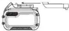
To Attach the Dust Bag (Fig. D)
- Fit the dust bag 40 to the dust port 36 as shown in Figure D.
To Empty the Dust Bag (Fig. D)
-
Remove dust bag 40 from the saw and gently shake or tap the dust bag to empty.
-
Reattach the dust bag back onto the dust port 36.
You may notice that all the dust will not come free from the bag. This will not affect cutting performance but will reduce the saw's dust collection efficiency. To restore your saw's dust collection efficiency, depress the spring inside the dust bag when you are emptying it and tap it on the side of the trash can or dust receptacle.
External Dust Extraction (Fig. AA)
When vacuuming dry dust that is especially detrimental to health or carcinogenic, use a special dust Class M vacuum cleaner.
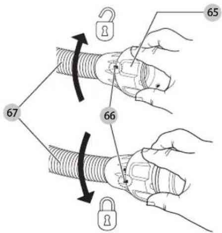
Connecting to an AirLock Compatible Dust Extractor (Fig. AA)
The dust port 36 on your mitre saw is compatible with the DeWALT AirLock connection system. The AirLock allows for a fast, secure connection between the dust extractor hose 67 and the mitre saw.
- Ensure the collar on the AirLock connector 65 is in the unlock position. Align notches 66 on collar and AirLock connector as shown for unlock and lock positions.
- Push the AirLock connector onto the dust port 36.
- Rotate the collar to the locked position. NOTE: The ball bearings inside collar lock into slot and secure the connection. The mitre saw is now securely connected to the dust extractor.
Wireless Tool Connect™ Compatible
This mitre saw has a built in wireless connection which can operate with a Wireless Tool Connect™ dust extractor. Once the saw and the Wireless Tool Connect™ compatible dust extractor are paired, the dust extractor will be controlled by the trigger switch on the mitre saw.
Use of XPS™ LED Worklight System (Fig. A1, A2)
NOTE: The mitre saw must have the battery pack inserted.
The XPS™ LED Worklight System is equipped with a temporary on switch 27 and can be activated manually. The XPS™ LED Worklight System also turns on when the trigger is activated and the blade is running.
To cut through an existing pencil line on a piece of wood:
- Turn on the XPS™ system, then pull down on the operating handle 2 to bring the saw blade close to the wood. The shadow of the blade will appear on the wood.
- Align the pencil line with the edge of the blade's shadow. You may have to adjust the mitre or bevel angles in order to match the pencil line exactly.
Through-Cutting Operations (Fig. A1, A2, P, Q)
If the slide feature is not used, ensure the saw head is pushed back as far as possible and the rail lock knob 6 is tightened. This will prevent the saw from sliding along its rails as the workpiece is engaged.
Cutting of multiple pieces is not recommended but can be done safely by ensuring that each piece is held firmly against the table and fence.
Straight Vertical Crosscut
- Set and lock the mitre arm at zero, and hold the wood firmly on the table 17 and against the fence 13.
- With the rail lock knob 6 tightened, turn on the saw by pushing the lock-off lever 25 and squeezing the trigger switch 24.
- When the saw comes up to speed, lower the arm smoothly and slowly to cut through the wood. Let the blade come to a full stop before raising arm.
Sliding Crosscut (Fig. A1, P)
When cutting anything larger than a 51 x 115 mm (51 x 82 mm at 45° mitre) workpiece, use an out-down-back motion with the rail lock knob 6 loosened.
Pull the saw out toward you, lower the saw head down toward the workpiece, and slowly push the saw back to complete the cut.
Do not allow the saw to contact the top of the workpiece while pulling out. The saw may run toward you, possibly causing personal injury or damage to the workpiece.
Mitre Crosscut (Fig. Q)
The mitre angle is often 45^ for making corners, but can be set anywhere from zero to 50^ left or 60^ right. Proceed as for a straight vertical crosscut. When performing a mitre cut on workpieces wider than 51 × 105 mm that are shorter in length, always place the longer side against the fence.
Bevel Cut (Fig. A1, A2)
Bevel angles can be set from 49° right to 49° left and can be cut with the mitre arm set between 50° left or 60° right. Refer to the Features and Controls section for detailed instructions on the bevel system.
- Loosen the bevel lock knob 33, and move the saw to the left or right as desired. It is necessary to move the fence 13 to allow clearance. Tighten the fence adjustment knob 12 after positioning the fences.
- Tighten the bevel lock firmly.
At some extreme angles, the right side fence might have to be removed. Refer to Fence Adjustment in the Adjustments section for important information on adjusting the fences for certain bevel cuts.
To remove the right fence, unscrew the fence adjustment knob 12 several turns and slide the fence out. The right fence is secured to the base with a lanyard to prevent it from being lost.
Quality of Cut
The smoothness of any cut depends on a number of variables, such as the material being cut, blade type, blade sharpness and rate of cut.
When smoothest cuts are desired for molding and other precision work, a sharp (60 tooth carbide) blade and a slower, even cutting rate will produce the desired results.
WARNING: Ensure that the material does not move or creep while clamping; clamp it securely in place. Always let the blade come to a full stop before raising arm. If small fibres of wood still split out at the rear of the workpiece, stick a piece of masking tape on the wood where the cut will be made. Saw through the tape and carefully remove tape when finished.
Non-Through-Cutting (Grooving and Rabbeting) (Fig. A2)
Your saw is equipped with a grooving stop 30, depth adjustment screw 29 and wing nut 28 to allow for groove cutting. Instructions in the Sliding Crosscuts, Bevel Cuts and Cutting Compound Mitres sections are for cuts made through the full thickness of the material. The saw can also perform non-through cuts to form grooves or rabbets in the material.
Grooving (Fig. A1, A2)
Refer to Grooving Stop for detailed instructions for setting depth of cut. A piece of scrap wood should be used to verify the desired depth of cut.
- Hold the wood firmly on the table and against the fence 13. Align the cut area underneath the blade. Position the saw arm fully forward, with blade in down position. Turn on the saw by pushing the lock-off lever 25 and squeezing the trigger switch 24. Smoothly, push saw arm rearward to cut a groove through the workpiece.
- Release the trigger switch with the saw arm down. When saw blade has completely stopped, raise the saw arm. Always let the blade come to a full stop before raising the arm.
- To widen the groove, repeat steps 1–2 until the desired width is obtained.
Clamping the Workpiece (Fig. C)
WARNING: A workpiece that is clamped, balanced and secure before a cut may become unbalanced after a cut is completed. An unbalanced load may tip the saw or anything the saw is attached to, such as a table or workbench. When making a cut that may become unbalanced, properly support the workpiece and ensure the saw is firmly bolted to a stable surface. Personal injury may occur.
WARNING: The clamp foot must remain clamped above the base of the saw whenever the clamp is used. Always clamp the workpiece to the base of the saw – not to any other part of the work area. Ensure the clamp foot is not clamped on the edge of the base of the saw.
CAUTION: Always use a work clamp to maintain control and reduce the risk of personal injury and workpiece damage.
Use the material clamp 39 provided with your saw. The left or right fence will slide from side to side to aid in clamping. Other aids such as spring clamps, bar clamps or C-clamps may be appropriate for certain sizes and shapes of material.
To Install Clamp
- There are four rectangular clamp mounting holes 68 in the base, two in the front and two on the back of the saw under the base fence. Insert the clamp 39 into one of the four holes.
NOTE: When assembling the clamp on the back side of the saw, the arm of the clamp will need to be at the highest position so that clamp post can be slid into the mounting hole as the clamp passes over the fence. - Loosen the knob to adjust the clamp up or down, tighten the knob to firmly clamp the workpiece.
NOTE: Place the clamp on the opposite side of the base when beveling. ALWAYS MAKE DRY RUNS (UNPOWERED) BEFORE FINISH CUTS TO CHECK THE PATH OF THE BLADE. ENSURE THE CLAMP DOES NOT INTERFERE WITH THE ACTION OF THE SAW OR GUARDS.
Support for Long Pieces (Fig. E)
ALWAYS SUPPORT LONG PIECES.
For best results, use the DE7023-XJ or DE7033 leg stands 41 to extend the table width of your saw. Support long workpieces using any convenient means such as sawhorses or similar devices to keep the ends from dropping.
Cutting Picture Frames, Shadow Boxes And Other Four-Sided Projects (Fig. R, S)
Try a few simple projects using scrap wood until you develop a "feel" for your saw. Your saw is the perfect tool for mitring corners like the one shown in Figure R.
Sketch 1 in Figure S shows a joint made with the bevel adjustment method.
The joint shown can be made using either method.
• Using bevel adjustment:
- The bevel for the two boards is adjusted to 45^ each, producing a 90^ corner.
- The mitre arm is locked in the zero position and the bevel adjustment is locked at 45°.
- The wood is positioned with the broad flat side against the table and the narrow edge against the fence.
• Using mitre adjustment:
- The same cut can be made by mitring right and left with the broad surface against the fence.
Cutting Trim Molding and Other Frames (Fig. S)
Sketch 2 in Figure S shows a joint made by setting the mitre arm at 45^ to mitre the two boards to form a 90^ corner. To make this type of joint, set the bevel adjustment to zero and the mitre arm to 45^ . Once again, position the wood with the broad flat side on the table and the narrow edge against the fence.
The two sketches in Figure S are for four-sided objects only. As the number of sides changes, so do the mitre and bevel angles. The chart below gives the proper angles for a variety of shapes, assuming that all sides are of equal length.
NUMBER OF SIDES MITRE OR BEVEL ANGLE
| 4 45° |
| 5 36° |
| 6 30° |
| 7 25.7" |
| 8 22.5° |
| 9 20° |
| 10 18° |
For a shape that is not shown in the chart, use the following formula: 180^ divided by the number of sides equals the mitre (if the material is cut vertically) or bevel angle (if the material is cut laying flat).
Cutting Compound Mitres (Fig. T)
A compound mitre is a cut made using a mitre angle and a bevel angle at the same time. This is the type of cut used to make frames or boxes with slanting sides like the one shown in Figure T.
WARNING: If the cutting angle varies from cut to cut, check that the bevel lock knob and the mitre lock handle are securely locked. These must be locked after making any changes in bevel or mitre.
The chart shown below will assist you in selecting the proper bevel and mitre settings for common compound mitre cuts.
- Select the desired angle A (Fig. T) of your project and locate that angle on the appropriate arc in the chart.
- From that point follow the chart straight down to find the correct bevel angle and straight across to find the correct mitre angle.
- Set your saw to the prescribed angles and make a few trial cuts. Practise fitting the cut pieces together.
Example: To make a 4-sided box with 26° exterior angles (Angle A, Fig. T), use the upper right arc. Find 26° on the arc scale. Follow the horizontal intersecting line to either side to get mitre angle setting on saw (42°). Likewise, follow the vertical intersecting line to the top or bottom to get the bevel angle setting on the saw (18°). Always try cuts on a few scrap pieces of wood to verify the settings on the saw.
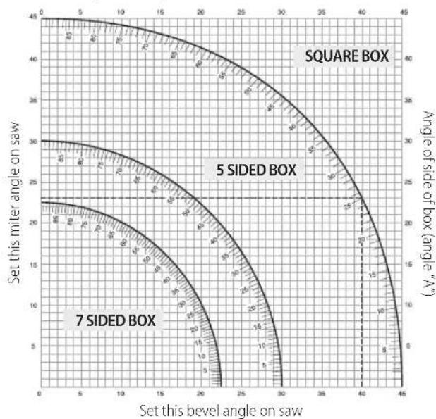
line
| Set this bevel angle on saw | Set this miter angle on saw | Angle of side of box (angle "A") | | --------------------------- | --------------------------- | -------------------------------- | | 0 | 45 | 45 | | 5 | 44 | 44 | | 10 | 43 | 43 | | 15 | 42 | 42 | | 20 | 41 | 41 | | 25 | 40 | 40 | | 30 | 39 | 39 | | 35 | 38 | 38 | | 40 | 37 | 37 | | 45 | 36 | 36 |Cutting Base Moulding (Fig. K, U)
To complete straight 90° cuts, position the wood against the fence and hold it in place as shown in Figure U. Turn on the saw, allow the blade to reach full speed and lower the arm smoothly through the cut.
Cutting Base Moulding from 70 mm up to 150 mm High Vertically Against the Fence (Fig. K, U)
NOTE: Use the slide lock lever 62, shown in Figure K, when cutting base moulding measuring from 70 mm to 150 mm high vertically against the fence.
Position material as shown in Figure U.
All cuts should be made with the back of the moulding against the fence and with the bottom of the moulding against the table.
| Inside Corner Outside Corner | |
| Left side Mitre left 45° | Mitre right 45° |
| Save left side of cut | Save left side of cut |
| Right side Mitre right 45° | Mitre left 45° |
| Save right side of cut | Save right side of cut |
Material up to 150 mm can be cut as described above.
Cutting Crown Moulding (Fig. A1, V1, V2)
Your mitre saw is well suited to the task of cutting crown moulding. In order to fit properly, crown moulding must be compound mitred with extreme accuracy.
Your mitre saw has special pre-set mitre latch points at 22.5°, 31.6° and 35.3° left and right for cutting crown moulding at the proper angle and bevel stop pawls at 22.5° and 30° left and right. There is also a mark on the bevel scale 10 at 33.9°. The chart below gives the proper settings for cutting crown moulding.
NOTE: Pretesting with scrap material is extremely important!
Instructions for Cutting Crown Moulding Laying Flat and Using the Compound Features (Fig. V1)
- Moulding should lay flat with the broad back surface down on the saw table 17.
- Place the top of the moulding against the fence 13.
- The settings below are for 45° sprung crown moulding.
| Inside Corner Outside Corner | |
| Left side Bevel left 30° | Bevel right 30° |
| Mitre table set at right 35.26° | Mitre table set at left 35.26° |
| Save left end of cut | Save left end of cut |
| Right side Bevel right 30° | Bevel left 30° |
| Mitre table set at left 35.26° | Mitre table set at right 35.26° |
| Save right end of cut | Save right end of cut |
- The settings below are for crown moulding with 52° angles at the top and 38° angles at the bottom.
| Inside Corner Outside Corner | |
| Left side Bevel left 33.9° | Bevel right 33.9° |
| Mitre table set at right 31.62° | Mitre table set at left 31.62° |
| Save left end of cut | Save left end of cut |
| Right side Bevel right 33.9° | Bevel left 33.9" |
| Mitre table set at left 31.62° | Mitre table set at right 31.62° |
| Save right end of cut | Save right end of cut |
Alternative Method for Cutting Crown Moulding
Cutting crown moulding using this method does not require a bevel cut. Minute changes in the mitre angle can be made without affecting the bevel angle. When corners other than 90° are encountered, the saw can be quickly and easily adjusted for them.
Instructions for Cutting Crown Moulding Angled Between the Fence and Base of the Saw for All Cuts (Fig. V2)
- Angle the moulding so the bottom of the moulding (the part which goes against the wall when installed) is against the fence 13 and the top of the moulding is resting on the saw table 17.
- The angled "flats" on the back of the moulding must rest squarely on the fence and saw table.
| Inside Corner Outside Corner | |
| Left side Mitre right at 45° | Mitre left at 45° |
| Save right side of cut | Save right side of cut |
| Right side Mitre left at 45° | Mitre right at 45° |
| Save left side of cut | Save left side of cut |
Special Cuts
WARNING: Never make any cut unless the material is secured on the table and against the fence.
Aluminum Cutting (Fig. W1, W2)
ALWAYS USE THE APPROPRIATE SAW BLADE MADE ESPECIALLY FOR CUTTING ALUMINUM.
Certain workpieces may require the use of a clamp or fixture to prevent movement during the cut. Position the material so that you will be cutting the thinnest cross section, as shown in Figure W1. Figure W2 illustrates the wrong way to cut these extrusions.
Use a stick wax cutting lubricant when cutting aluminum. Apply the stick wax directly to the saw blade 46 before cutting. Never apply stick wax to a moving blade. The wax provides proper lubrication and keeps chips from adhering to the blade.
Bowed Material (Fig. X1, X2)
When cutting bowed material always position it as shown in Figure X1 and never like that shown in Figure X2. Positioning the material incorrectly will cause it to pinch the blade.
Cutting Plastic Pipe or Other Round Material
Plastic pipe can be easily cut with your saw. It should be cut just like wood and CLAMPED OR HELD FIRMLY TO THE FENCE TO KEEP IT FROM ROLLING. This is extremely important when making angle cuts.
Cutting Large Material (Fig. Y)
Occasionally you will encounter a piece of wood a little too large to fit beneath the lower guard. If this occurs, place your right thumb on the
upper side of the guard 1 and roll the guard up just enough to clear the workpiece, as shown in Figure Y. Avoid doing this as much as possible, but if need be, the saw will operate properly and make the bigger cut. NEVER TIE, TAPE, OR OTHERWISE HOLD THE GUARD OPEN WHEN OPERATING THIS SAW.
MAINTENANCE
Your power tool has been designed to operate over a long period of time with a minimum of maintenance. Continuous satisfactory operation depends upon proper tool care and regular cleaning.
WARNING: To reduce the risk of serious personal injury, turn to off and disconnect battery pack before making any adjustments or removing/installing attachments or accessories.
An accidental start-up can cause injury.
The charger and battery pack are not serviceable.

Lubrication
Your power tool requires no additional lubrication.

Cleaning
WARNING: Blow dirt and dust out of the main housing with dry air as often as dirt is seen collecting in and around the air vents. Wear approved eye protection and approved dust mask when performing this procedure.
WARNING: Never use solvents or other harsh chemicals for cleaning titanium-metallic parts of the tool. These chemicals may weaken the materials used in these parts. Use a cloth dampened only with water and mild soap. Never let any liquid get inside the tool; never immerse any part of the tool into a liquid.
Before use, carefully check the upper guard, lower guard and dust duct to determine that they will operate properly. Ensure that chips, dust or workpiece particles do not block of one of the functions.
In case of workpiece fragments jammed between the saw blade and guards, remove the battery pack from the machine and follow the instructions given in Changing or Installing a New Saw Blade. Remove the jammed parts and reassemble the saw blade.
Periodically clean all dust and wood chips from around AND UNDER the base and the rotary table.
Worklight Cleaning
- Carefully clean sawdust and debris from worklight lens with a cotton swab. Dust build-up can block the worklight and prevent it from accurately indicating the line of cut.
• DO NOT use solvents of any kind; they may damage the lens. - With blade removed from saw, clean pitch and build-up from blade.
Dust Duct Cleaning
With the saw unplugged and the saw head raised fully, low pressure air or a large diameter dowel rod can be used to clear the dust out of the dust duct.
Optional Accessories
WARNING: Since accessories, other than those offered by DiWALT, have not been tested with this product, use of such accessories with this tool could be hazardous. To reduce the risk of injury, only DiWALT recommended accessories should be used with this product.
Consult your dealer for further information on the appropriate accessories.
Clamp: DW7090-XJ (Fig. C)
The clamp 39 is used for firmly clamping workpiece to the saw table.
Quick Release Clamps: DWS5026-XJ
Dust Bag: DW7053-QZ (Fig. D)
Equipped with a zipper for easy emptying, the dust bag 40 will capture the majority of the sawdust produced.
Leg Stands: DE7023-XJ, DE7033-XJ (Fig. E)
The leg stand 41 is used to extend the table width of the saw.
Clamp Brackets: DE7025-XJ (Fig. F)
The clamp brackets 42 are used for mounting the saw to a stand.
SAW BLADES: ALWAYS USE 250 mm SAW BLADES WITH 30 mm ARBOUR HOLES. SPEED RATING MUST BE AT LEAST 4300 RPM. Never use a smaller diameter blade. It will not be guarded properly. Use crosscut blades only! Do not use blades designed for ripping, combination blades or blades with hook angles in excess of 5°.
BLADE DESCRIPTIONS
| APPLICATION DIAMETER TEETH | ||
| Construction Saw Blades (thin kerf with anti-stick rim) | ||
| General Purpose 250 mm 40 | ||
| Fine Crosscuts 250 mm 60 | ||
| Woodworking Saw Blades (provide smooth, clean cuts) | ||
| Fine crosscuts 250 mm 80 | ||
| Non-ferrous metals 250 mm 96 | ||
Protecting the Environment
Separate collection. Products and batteries marked with this symbol must not be disposed of with normal household waste.
Products and batteries contain materials that can be recovered or recycled reducing the demand for raw materials. Please recycle
electrical products and batteries according to local provisions. Further information is available at www.2helpU.com.
Rechargeable Battery Pack
This long life battery pack must be recharged when it fails to produce sufficient power on jobs which were easily done before. At the end of its technical life, discard it with due care for our environment:
- Run the battery pack down completely, then remove it from the tool.
- Li-ion cells are recyclable. Take them to your dealer or a local recycling station. The collected battery packs will be recycled or disposed of properly.
SIERRA DE INGLETES
DCS727
¡Enhorabuena!
(Isolation double) – outils
Batterie rechargeable
Vice-President Engineering, PTE-Europa
DEWALT, Richard-Slinger-Strase 11,
*Datumcode 201811475B of later
**Datumcode 201536 of later
ALGEMENE VEILIGHEIDSWAARSCHUWINGEN VOOR ELEKTRISCH GEREEDSCHAP

BEWAAR ALLE WAARSCHUWINGEN EN INSTRUCTIES ALS TOEKOMSTIG REFERENTIEMATERIAAL
D-65510, Idstein, Germany
14.06.2019