
MS 1706 FR - Grinder Flex - Free user manual and instructions
Find the device manual for free MS 1706 FR Flex in PDF.


User questions about MS 1706 FR Flex
0 question about this device. Answer the ones you know or ask your own.
Ask a new question about this device
Download the instructions for your Grinder in PDF format for free! Find your manual MS 1706 FR - Flex and take your electronic device back in hand. On this page are published all the documents necessary for the use of your device. MS 1706 FR by Flex.
USER MANUAL MS 1706 FR Flex
natural_image
Illustration of a precision cutting tool with a mounted cylindrical head and base (no text or symbols visible)MS 1706 FR
318.779/05.06

text_image
itext_image
Icon set showing an open book with an 'i' symbol, a person wearing sunglasses, and a crossed-out trash bin symbol.natural_image
Close-up of a computer mouse control panel with a downward arrow and navigation icon (no text or symbols on the panel itself)natural_image
Mechanical tool with gear and control panel, shown in action (no text or symbols visible)text_image
a c d e cnatural_image
Illustration of a mechanical device with a downward arrow and internal components, shown in two views (no text or symbols)natural_image
Illustration of a cutting machine with a curved arrow indicating motion (no text or symbols)natural_image
Illustration of a hand using a tool to adjust or install a mechanical component, with no visible text or symbols.natural_image
Illustration of hands using a handheld device to interact with a spherical object (no text or symbols visible)Symbols used in this manual ..... 13
Technical specifications ..... 13
Overview 14
Supplied components ..... 15
Operating instructions ..... 17
Maintenance and care ..... 21
Disposal information ..... 21
CE Declaration of Conformity ..... 22
Guarantee 22
Symbols used in this manual

Danger!
Denotes impending danger. Non-observance of this warning may result in death or extremely severe injuries.
Caution!
Denotes a possibly dangerous situation. Non-observance of this warning may result in slight injury or damage to property.

Note
Denotes application tips and important information.
Symbols on the power tool

Before switching on the power tool, read the operating manual!
Wear goggles!


Disposal information for the old machine!
(See page 21)
Technical specifications
| Machine type MS 1706 FR | ||
| Cutting depth mm 0–35 | ||
| Groove width mm 10–30 | ||
| Disc diameter mm 140 | ||
| Tool holder M 14 | ||
| Speed (at no load) | min^-1 | 7500 |
| Power input W 1400 | ||
| Power output | W | 950 |
| Weight (without power cord) | kg | 3.7 |
| Safety class | II / [IMAGE] | |
Overview
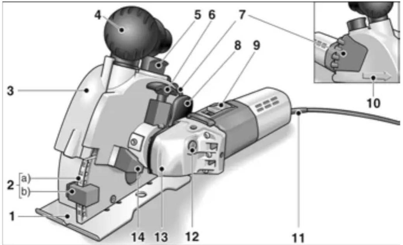
text_image
Technical diagram of a hairpin with numbered parts and an inset close-up view showing the insertion process.1 Milling table
2 Milling depth adjustment
a) Milling depth scale
b) Milling depth stop
3 Guard hood
4 Handle/Intake flange
5 Lock for guard hood
6 Release handle
for swivelling off the drive unit
7 Handle
8 Release rocker
for lowering the milling unit
9 S w i t c h
Switches the power tool on and off.
10 Cutting direction arrow
11 4.0 m power cord with plug
12 Spindle lock
Secures the spindle when the tool is changed.
13 Gearbox with direction of rotation arrow
14 Stop
when swivelling off the drive unit
15 Rating plate *
Supplied components
Wall chaser MS 1706 FR
2 diamond cutting discs (part no.: 303.593)
1 SDS-Clic quick-release clamping nut (part no.: 253.049)
2 clamping flanges (part no.: 191.612)
5 distance washers 5 mm (part no.: 318.914)
1 adapter for dust extractor 32/28 mm (part no.: 327.026)
1 web remover (part no.: 229.253)
1 Plastic carrying case (part no.: 327.034)
1 operating manual (part no. 318.779)
Important safety information

Danger!
Before using the wall chaser, please read and follow:
– these operating instructions,
- the "General safety instructions" on the handling of power tools in the enclosed booklet (leaflet-no. 315.915/04.04),
– the currently valid site rules and the regulations for the prevention of accidents.
This wall chaser is state of the art and has been constructed in accordance with the acknowledged safety regulations.
Nevertheless, when in use, the power tool may be a danger to life and limb of the user or a third party, or the power tool or other property may be damaged. The wall chaser may be operated only if it is
– used as intended,
– in perfect working order.
Faults which impair safety must be repaired immediately.
Noise
Caution
Wear ear protection at a sound pressure above 85 dB(A).
Measured according to EN 50144:
| Sound pressure L_pA [dB(A)] | Sound power L_WA [dB(A)] | |
| MS 1706 FR | 86 97 |
Vibration
Weighted effective value of acceleration according to EN 50144: 2.5 m/s ^4
Intended use
This wall chaser is designed
– is designed for industrial applications,
– for chasing and separating mineral materials without the addition of water
– for use with diamond cutting discs and accessories which are indicated in this manual or recommended by the manufacturer.
Safety instructions

Danger!
■When using the power tool, wear protective equipment: Dust mask, goggles, ear protection, protective gloves, sturdy shoes.
■Switch on the wall chaser before guiding it towards the workpiece.
■Do not load the wall chaser to such an extent that it comes to a standstill.
■When working, guide the wall chaser with both hands. Ensure that you have a secure footing.
■Never clamp the wall chaser in a vice.
■Before plugging in the power cord (11), ensure that the machine is switched off.
■Always lay the power cord (11) to the rear away from the wall chaser.
■Use only diamond cutting discs which have a permitted speed at least as high as the idling speed of the power tool.
■Use only diamond cutting discs which fit the chuck. Do not use reducers or adapters.
■Before using the power tool, check that the tools have been fitted and attached correctly. Switch on the machine at no load for 30 seconds!
Interrupt the test run immediately if violent vibrations occur or other damage is established. Check the machine to determine the cause.
■Caution when working in unknown areas!
Electric, gas or water lines below the surface may be damaged.
Use suitable detectors to scan the work area beforehand.
■Caution when working in supporting walls! Observe structural calculations!
Before starting work, obtain the permission of the structural engineer, architect or site manager responsible.
The permitted chasing depth depends on the chasing length, wall thickness and building material.
■Do not work in materials which release hazardous substances (e.g. asbestos).
■During operation the wall chaser must be connected to a dust extractor.
The extraction system must be authorised to extract stone dust.
An authorised special extractor must be used to extract particularly harmful, carcinogenic, dry dust.
■Keep hands away from rotating tools.
■Before putting down the power tool, switch it off and wait until it comes to a standstill.
■Blocking the cutting discs will result in considerable recoil forces. Switch off the power tool immediately.
■Do not use the wall chaser in rain or in a damp environment.
■If wall chasers are used outdoors or are exposed to excessive amounts of metal dust, connect them via a residual-current-operated circuit-breaker (tripping current maximum 30 mA).
■Use only extension cables permitted for outdoor use.
■Identify the wall chaser with stickers only. Do not drill any holes into the housing.
Damage to property!
■The mains voltage and the voltage specifications on the rating plate (15) must correspond.
Operating instructions

Danger!
Before performing any work on the power tool, pull out the mains plug.
Before switching on the angle grinder
■Unpack the wall chaser and check that no parts are missing or damaged.
Switch on and off
Caution!
Following a power failure, the switched-on machine will start running again.
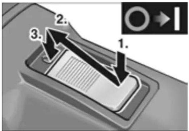
text_image
1. 2. 3.- Press the switch (9) and push forwards. - Lock the switch by depressing it at the front.
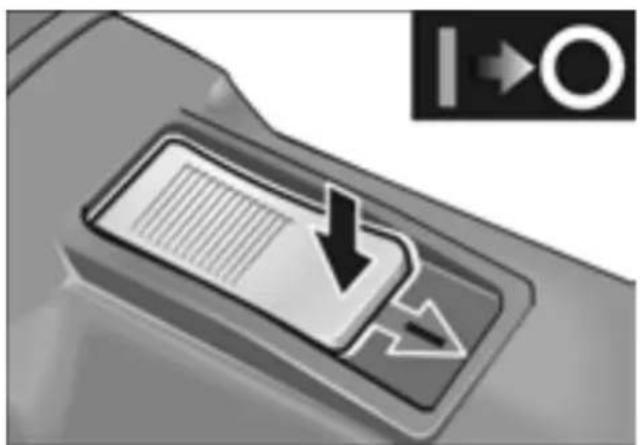
natural_image
Close-up of a device's internal panel with a downward arrow and grid pattern, next to an icon indicating direction (no text or symbols on the diagram itself)- To switch off the wall chaser, release the switch by pressing it at the back.
Changing the cutting discs/ changing the groove width
Caution!
Risk of injury! Wear protective gloves.
- Pull out the mains plug.
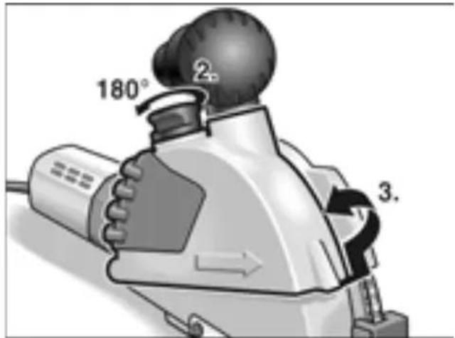
text_image
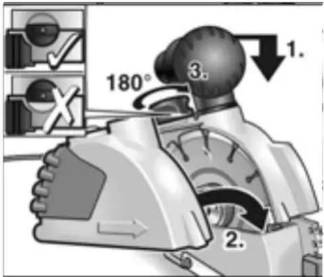
180° ② 3.- Lift the lock (5) for the guard hood and rotate by 180^ .
- Remove the guard hood (3).
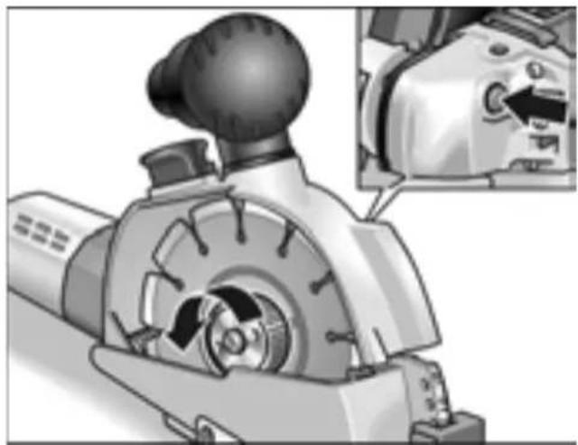
natural_image
Mechanical device with gear and control panel, shown from side profile (no text or symbols visible)- Press the spindle lock (12) and loosen the quick-release clamping nut.

Danger!
Risk of injury and damage.
The direction of rotation indicated on the cutting disc must agree with the direction-of-rotation arrow on the gearbox (13).

Note
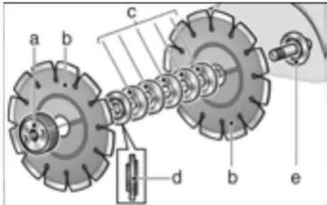
The rough side of the quick-release clamping nut always faces the cutting disc or distance washer.
text_image
a b c d b e- Remove the cutting discs (b), clamping flange (d) and distance washers (c).
To change the cutting discs:
■Attach new cutting discs (b), distance washers (c) and clamping flange (d) in reverse sequence.
■Screw on the quick-release clamping nut (a). Depress the spindle lock (12) and manually tighten the quick-release clamping nut (a).
To change the groove width:
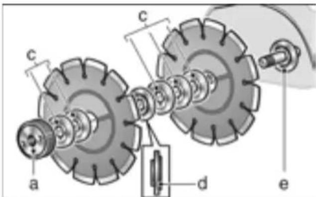
The groove width can be set by rearranging the distance washers.

Note
The minimum groove width is 10 mm. In all distance washers (c) are fitted in front of the quick-release clamping nut (a).
text_image
a c d e c■Attach the cutting disc (b), distance washers (c) according to the required groove width and clamping flange (d).
■Attach the remaining distance washers (c).
■Screw on the quick-release clamping nut. Depress the spindle lock (12) and manually tighten the quick-release clamping nut (a).
text_image
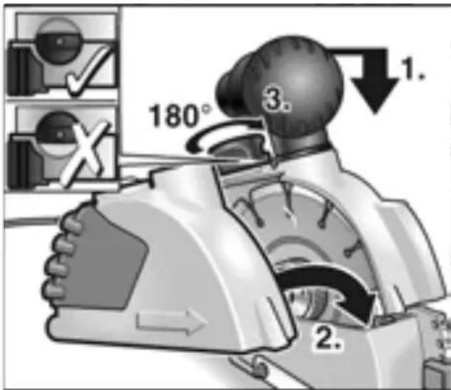
180° 2. 3. 1.- Gently depress the milling unit and attach the guard hood (3).
- Lift lock (5) for guard hood and rotate by 180° until it engages.
- Insert the mains plug into the socket.
- Switch on the wall chaser (without locking the switch) and leave running for approx. 30 seconds. Check for quiet running.
Adjusting the cutting depth
- Pull out the mains plug.
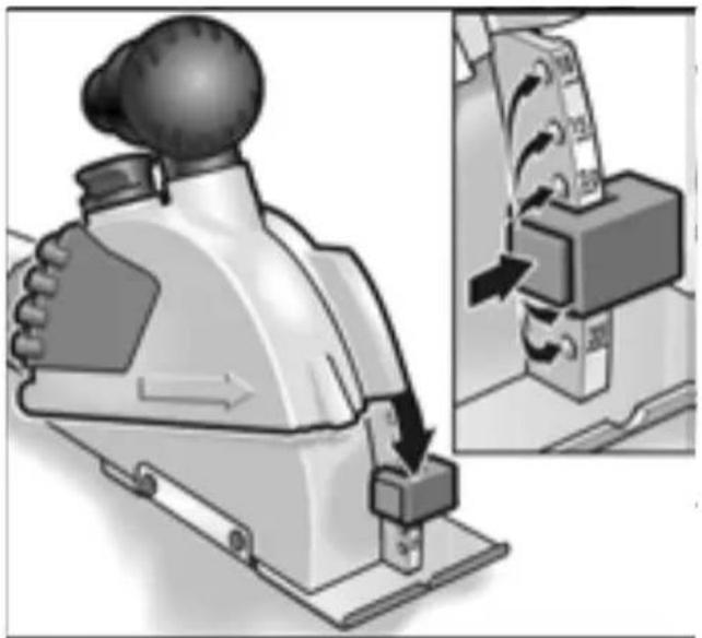
natural_image
Illustration of a mechanical device with a downward arrow indicating motion, alongside a close-up view of its internal components (no text or symbols visible)- Depress the lock on the milling depth stop (2b) and set the stop to the required depth. Lock the milling depth stop (2b) at the required depth.
Dust extractor
Caution!
During operation the wall chaser must be connected to a dust extractor.
The extraction system must be authorised to extract stone dust.
An authorised special extractor must be used to extract particularly harmful, carcinogenic, dry dust.
If the extraction system malfunctions, stop working immediately and switch off the power tool. Repair the fault before switching on the power tool again.
■Connect the hose from the extraction system to the intake flange. Check the attachment! If required, use an appropriate adapter.
Making cuts

Danger!
The stipulated cutting direction is indicated by the cutting-direction arrow (10) on the guard hood and must always be observed.
Always guide the wall chaser with both hands. Use the designated gripping areas. One hand on the power tool, the other hand on the handle (4) or (7).
If there is a risk of cutting through live cables, do not touch the metal parts of the machine.
Diamond cutting discs become very hot during operation. Do not touch them until they have cooled down.
- Position the power tool milling table (1) fully on the area which is to be processed. To align with marks, use the notch in the milling table.
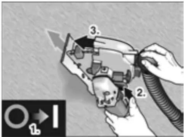
text_image
Diagram showing a hand operating a device with labeled parts and directional arrows, including numbered annotations.-
Switch on the device.
-
Press the release rocker (8) and slowly lower the milling unit and immerse into the material.
-
Move the wall chaser in the indicated cutting direction.
-
After making the cut, swivel the power tool – with the motor running – all the way out of the groove until the release rocker (8) engages.

Note
When the power tool is switched off, the tool continues running briefly.
- Switch off the power tool.
- Remove the remaining web with the supplied web remover.
Swivelling the motor unit
To improve guiding the cut and handling, the drive unit can be swivelled.
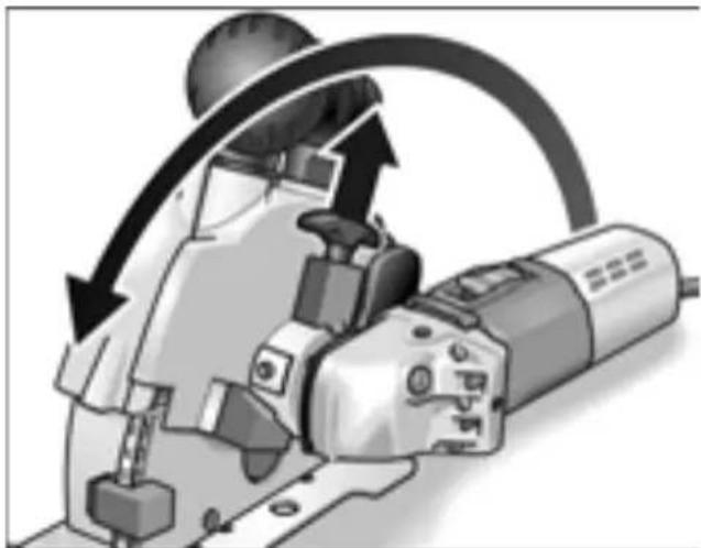
natural_image
Mechanical tool with curved arrows indicating motion or force direction (no text or symbols)■Pull up the release handle (6) and swivel the motor unit as far as it will go. The release handle must engage in the new position.
The user can now adopt an ergonomically favourable posture when making a drawing cut.
Operating instructions
To make vertical cuts, swivel the motor unit as described previously.
Place the machine above and pull downwards.
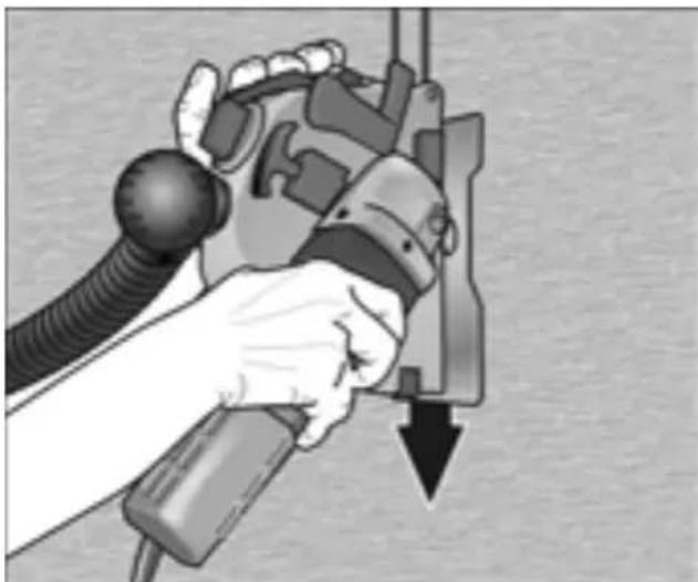
natural_image
Illustration of a hand using a handheld device to adjust or install a mechanical component, with no visible text or symbols.Your right hand guides the motor unit, your left hand pulls on the handle (7).
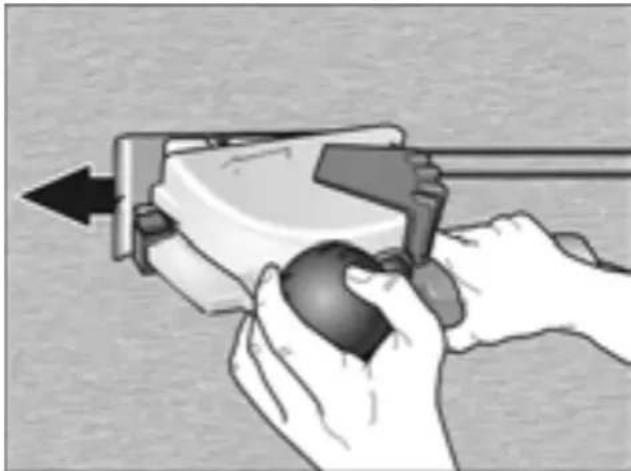
To make horizontal cuts, push the power tool.
natural_image
Illustration of hands using a handheld device to interact with a sphere (no text or symbols visible)Your right hand guides the motor unit, your left hand is placed on the handle/intake flange (4)
Tips
When making cuts in a very hard material, the diamond cutting disc may overheat and be damaged.
■Immediately stop cutting and leave the cutting disc to cool down at no-load speed.
A spark ring around the cutting disc and a decreasing cutting rate are signs of a blunt cutting disc.
■Short cuts in abrasive materials, e.g. the sharpening stone for diamond tools in the range of accessories, sharpen the cutting disc.
■If this does not improve the cutting performance, replace the cutting discs.
For further information on the manufacturer's products go to www.flex-tools.de.
Maintenance and care

Danger!
Before performing any work on the wall chaser, pull out the mains plug.
Cleaning
Regularly clean the power tool and ventilation slots. Frequency of cleaning is dependent on the material and duration of use.
Regularly blow out the housing interior and motor with dry compressed air.

Note!
Do not open the wall chaser during the warranty period. Non-compliance will deem the guarantee obligations of the manufacturer null and void.
Repairs
Repairs may be carried out by an authorised customer service centre only.
Spare parts and accessories
| Spare-part/Accessory Order | no. |
| 1 adapter 32/28 mm for suction hose | 251.847 |
| Universal adapter 25–32 mm 259.827 | |
Other accessories can be found in the manufacturer's catalogues.
Diamond cutting discs
| Dimensions [mm] | Order no. | |
| For masonry and render with additional lateral diamond segments to protect the steel core | ||
| 1 items per unit | ∅ 140 253.120 | |
| For tiles and ceramic bonded materials to ensure very precise, sharp-edged channels | ||
| 1 items per unit | ∅ 140 252.290 | |
| For rapid cutting of masonry, limestone and concrete. Especially hard with large gaps between segments for improved cooling and optimum dust extraction | ||
| 1 items per unit | ∅ 140 303.593 | |
| Sharpening stone for diamond tools | ||
| 1 items per unit | 320x160x30 251 | 756 |
Disposal information

Danger!
Render redundant power tools unusable by removing the power cord.

EU countries only
Do not throw electric power tools into the household waste!
In accordance with the European Directive 2002/96/EG on Waste Electrical and Electronic Equipment and transposition into national law used electric power tools must be collected separately and recycled in an environmentally friendly manner.

Note!
Please ask your dealer about disposal options!
CE Declaration of Conformity
We hereby declare that this product corresponds with the following standards or normative documents:
EN 50144, EN 55014, EN 61000 in accordance with the regulations stipulated in the directives 73/23/EWG, 89/336/EWG, 98/37/EG.
C∈06

text_image
2Lia SainaninRühle Severin
When a new machine is purchased, FLEX issues the end user with a 2-year manufacturer's warranty which comes into force on the date the machine was purchased.
The guarantee covers only defects which can be attributed to a material and/or production fault as well as non-performance of warranted characteristics. When making a claim under the guarantee, enclose the original sales receipt with purchase date. Repairs under the guarantee may be carried out only by workshops or service centres authorised by Flex.
A claim may be made under the guarantee only if the power tool has been used as intended. The guarantee excludes in particular operational wear, improper use, partly or completely dismantled machines as well as damage caused by overloading the machine, use of non-permitted, defective or incorrectly used application tools. Damage which is caused by the machine on the application tool or workpiece, use of force, consequential
damage which can be attributed to improper or inadequate maintenance on the part of the customer or a third party, damage caused by external effects or foreign objects, e. g. sand or stones, as well as damage caused by non-observance of the operating manual, e. g. connection to an incorrect mains voltage or current type. Claims for insertable tools or accessories can only be made under the guarantee provided they are used with power tools for the intended or permitted use.
Exemption from liability
The manufacturer and his representative are not liable for any damage and lost profit due to interruption in business caused by the product or by an unusable product.
The manufacturer and his representative are not liable for any damage which was caused by improper use of the power tool or by use of the power tool with products from other manufacturers.
Table des matières
natural_image
Close-up of a computer mouse control panel with a downward arrow and navigation icon (no text or symbols on the panel itself)natural_image
Mechanical device with a head-mounted knob and internal gear mechanism, shown in technical illustration (no text or symbols)text_image
Technical diagram of a mechanical gear assembly with labeled components a, c, d, enatural_image
Illustration of a mechanical device with directional arrows indicating motion, alongside a close-up of its internal components (no text or symbols visible)natural_image
Illustration of a cutting machine with a curved arrow indicating motion (no text or symbols)natural_image
Illustration of a hand using a handheld device to press or install a mechanical component, with a downward arrow indicating motion (no text or symbols present)natural_image
Illustration of hands using a tool to interact with a device, showing a mechanical setup (no text or symbols visible)natural_image
Close-up of a computer interface button with a downward arrow and document symbol (no readable text or labels)natural_image
Mechanical tool with gear and control panel, showing mechanical assembly (no text or symbols visible)text_image
a c d e cnatural_image
Illustration of a manual machine tool interacting with a control panel, showing a close-up of the mechanism (no text or symbols present)natural_image
Illustration of a mechanical tool with motion arrows indicating rotation or movement (no text or symbols)natural_image
Illustration of a hand using a handheld device to lift a motor, with a downward arrow indicating force or motion (no text or symbols present)natural_image
Illustration of hands using a tool to interact with a device, no text or symbols presenttext_image
Zhu SowaiuRühle Severin
natural_image
Close-up of a device's internal panel with a downward arrow and grid pattern, no visible text or symbolsnatural_image
Mechanical device with gear and adjustment knob, shown in two views (no text or symbols)text_image
a c d e cnatural_image
Illustration of a mechanical device with a hand operating a switch, showing internal components and motion arrows (no text or symbols)text_image
Diagram showing a hand operating a device with labeled parts and directional arrows, including numbered annotations.natural_image
Mechanical device with curved arrow indicating motion or rotation (no text or symbols visible)natural_image
Illustration of a hand gripping a mechanical device with a downward arrow (no text or symbols)natural_image
Illustration of a hand using a handheld device to interact with a spherical object (no text or symbols visible)text_image
Technical diagram of a hairpin with numbered parts and an inset close-up view showing the insertion point.natural_image
Close-up of a computer control panel with a downward arrow and navigation icon (no text or symbols on the panel itself)natural_image
Mechanical device with gear and control knob, shown in technical view (no text or symbols)text_image
a c d e cnatural_image
Illustration of a mechanical device with directional arrows indicating movement or force, alongside a close-up of its internal components (no text or symbols visible)text_image
Diagram showing a hand operating a device with labeled parts and directional arrows, including numbered annotations 1, 2, and 3.natural_image
Mechanical tool with curved arrow indicating rotation or motion (no text or symbols visible)natural_image
Illustration of a hand holding a mechanical device with a downward arrow, no text or symbols presentnatural_image
Illustration of hands using a tool to interact with a device, showing a black arrow indicating direction (no text or symbols present)EN 50144, EN 55014, EN 61000 de acordo com as determinações das Directivas 73/23/EWG, 89/336/EWG, 98/37/EG.

text_image
21a S###Rühle Severin
text_image
Technical diagram of a power tool with numbered parts and an inset close-up view showing the component's assembly.1 Freestafel
2 Freesdiepteverstelling
natural_image
Close-up of a device control panel with a downward arrow and grid pattern, no visible text or symbolsnatural_image
Mechanical tool with gear and adjustment knob, shown in action view (no text or symbols)text_image
a c d e cnatural_image
Illustration of a mechanical device with a hand operating a button, showing a close-up of its internal mechanism (no text or symbols present)natural_image
Mechanical tool with curved arrow indicating motion or rotation (no text or symbols visible)natural_image
Illustration of a hand using a tool to lift a mechanical component, with a downward arrow indicating force or direction (no text or symbols present)natural_image
Illustration of hands using a handheld device to interact with a spherical object (no text or symbols visible)text_image
B. L. S. W. D. A.Rühle Severin
text_image
Icon set with an open book, a person wearing sunglasses, and a trash can symbolizing online waste or disposal.natural_image
Close-up of a computer mouse control panel with a downward arrow and navigation icon (no text or symbols)natural_image
Mechanical component with gear and adjustment knob, shown in action (no text or symbols)text_image
a c d e cnatural_image
Illustration of a mechanical device with directional arrows indicating motion, showing internal components and a close-up view (no text or symbols)text_image
Diagram showing a hand operating a device with labeled parts and directional arrows, including numbered annotations.natural_image
Mechanical tool with curved arrow indicating rotation or motion (no text or symbols visible)natural_image
Illustration of a hand using a handheld device to adjust or install a mechanical component, with no visible text or symbols.natural_image
Illustration of hands using a handheld device to interact with a spherical object (no text or symbols visible)natural_image
Close-up of a device's internal panel with a black downward arrow and directional symbol (no readable text or labels)natural_image
Mechanical device with gear and control panel, shown in action view (no text or symbols)text_image
a c d e cnatural_image
Illustration of a robotic device with a close-up view showing internal components (no text or symbols)natural_image
Mechanical tool with curved arrows indicating motion or rotation (no text or symbols visible)natural_image
Illustration of a hand using a handheld device to interact with a mechanical component, showing a downward arrow (no text or symbols present)natural_image
Illustration of hands using a tool to interact with a device, no text or symbols presentnatural_image
Close-up of a device control panel with a downward arrow and navigation icon (no readable text or symbols)natural_image
Mechanical device with gear and control panel, shown in action view (no text or symbols)text_image
a c d e cnatural_image
Illustration of a mechanical device with directional arrows indicating motion, showing internal components and a close-up view (no text or symbols)natural_image
Mechanical device with rotating arm and circular motion arrow (no text or symbols)natural_image
Hand operating a mechanical device with a downward arrow indicating action (no text or symbols present)natural_image
Illustration of hands using a handheld device to interact with a spherical object (no text or symbols visible)text_image
Zhu SowaiuRühle Severin
text_image
Technical diagram of a hairpin with numbered parts and an inset close-up view showing the insertion process.1 Jyrsinpöytä
natural_image
Close-up of a device control panel with a downward arrow and grid pattern, no visible text or symbolsnatural_image
Mechanical device with gear and control panel, shown in side profile (no text or symbols visible)text_image
a c d e cnatural_image
Illustration of a mechanical device with a knob and directional arrow, showing internal components (no text or symbols)natural_image
Illustration of a cutting tool with a curved arrow indicating rotation (no text or symbols)natural_image
Illustration of a hand using a handheld device to adjust or install a mechanical component, with no visible text or symbols.natural_image
Illustration of hands using a handheld device to interact with a spherical object (no text or symbols visible)natural_image
Close-up of a computer mouse control panel with a downward arrow and navigation icon (no text or symbols on the panel itself)natural_image
Mechanical device with a head-mounted knob and gear mechanism, showing a close-up inset of the dial (no text or symbols visible)text_image
Technical diagram of a mechanical gear assembly with labeled components a, c, d, enatural_image
Illustration of a hand operating a manual switch mechanism, showing the lever and control panel (no text or symbols present)natural_image
Mechanical device with curved arrow indicating rotation or motion (no text or symbols visible)natural_image
Illustration of a hand operating a mechanical device with a downward arrow (no text or symbols)natural_image
Illustration of hands using a handheld device to interact with a spherical object (no text or symbols visible)natural_image
Close-up of a mechanical component with a downward arrow and internal grid pattern, no visible text or symbols.natural_image
Mechanical device with gear and control panel, showing a person operating it (no text or symbols visible)text_image
a c d e cnatural_image
Illustration of a mechanical device with directional arrows indicating motion or force, showing internal components (no text or symbols)text_image
Diagram showing a hand operating a device with labeled parts and directional arrows, including '1' and '2' annotations.natural_image
Mechanical tool with curved arrow indicating rotation or motion (no text or symbols visible)natural_image
Illustration of a hand holding a tool with a downward arrow, no text or symbols presentnatural_image
Illustration of hands using a handheld device to interact with a spherical object (no text or symbols visible)natural_image
Close-up of a file folder with a downward arrow icon, no visible text or symbolsnatural_image
Mechanical tool with gear and control panel, shown in technical view (no text or symbols)text_image
a c d e cnatural_image
Illustration of a hand operating a manual machine with a close-up view showing the mechanism (no text or symbols present)natural_image
Illustration of a mechanical tool with motion arrows indicating rotation or movement (no text or symbols)natural_image
Hand operating a manual electric shaver with a downward arrow indicating action (no text or symbols present)natural_image
Illustration of hands using a handheld device to interact with a spherical object (no text or symbols visible)natural_image
Close-up of a document tab with a downward arrow and directional arrow icon (no readable text or symbols)natural_image
Mechanical tool with gear and adjustment knob, shown in action (no text or symbols)text_image
Technical diagram of a mechanical gear assembly with labeled components a, c, d, enatural_image
Illustration of a manual switch mechanism with a close-up view showing the internal components (no text or symbols present)natural_image
Illustration of a cutting machine with a curved arrow indicating motion (no text or symbols)natural_image
Illustration of a robotic hand holding a mechanical device with a downward arrow (no text or symbols)natural_image
Illustration of hands using a tool to interact with a device, no text or symbols presentnatural_image
Close-up of a document icon with a downward arrow, no readable text or symbols presentnatural_image
Mechanical device with gear and control panel, showing mechanical components (no text or symbols visible)text_image
a c d e cnatural_image
Illustration of a mechanical device with a downward arrow indicating force or movement, alongside a close-up view of its internal components (no text or symbols visible)text_image
Diagram showing a hand operating a device with labeled parts and directional arrows, including numbered annotations.natural_image
Illustration of a mechanical tool with a curved arrow indicating motion or direction (no text or symbols)natural_image
Illustration of a hand using a handheld device to interact with a mechanical component, showing a downward arrow (no text or symbols present)natural_image
Illustration of hands using a tool to interact with a sphere (no text or symbols visible)text_image
Technical diagram of a power tool with numbered parts and an inset close-up view showing the component's assembly.1 Frézovací stôl
2 Prestavenie híbky frézovania a) Stupnica híbky frézovania b) Doraz híbky frézovania
3 Ochranný kryt
4 Rukovät/Sacie hrdlo
natural_image
Close-up of a document icon with a downward arrow, next to an icon with a right-pointing arrow (no text or symbols)natural_image
Mechanical device with gear and control panel, showing mechanical components (no visible text or symbols)- Stlačte aretáciu vretena (12) a povol'te rýchloupínaciu maticu.

Nebezpečenstvo!
text_image
a c d e c■Nasad'te rozbrusovací kotúč (b), dištančné podložky (c) podl'a želanej širky drážky a upínaciu prírubu (d).
■Nasad'te ostatné dištančné podložky (c).
■Naskrutkujte rýchloupínaciu maticu.
Stlačte aretáciu vretena (12) a rukou
pevne utiahnite rýchloupínaciu maticu (a).
text_image
180° 3. 2. 1.natural_image
Illustration of a mechanical device with directional arrows indicating motion or force, alongside a close-up view of its internal components (no text or symbols visible)- Stlačte blokovanie na doraze híbký frézovania (2b) a nastavte doraz na želanú híbku. Doraz híbký frézovania (2b) musí zaskočit u želanej híbký.
Odsávanie prachu
Pozor!
text_image
Diagram showing a hand operating a device with labeled parts and directional arrows, including numbered annotations.natural_image
Mechanical device with curved arrow indicating rotation or motion (no text or symbols visible)■Tiahnite odblokovaciu rukovät (6) smerom nahor a natáčajte motorovú jednotku až po doraz. Odblokovacia rukovät musí v novej polohe zaskočit.
natural_image
Illustration of a robotic hand holding a tool, with a downward arrow indicating action (no text or symbols present)Pravá ruka vedie motorovú jednotku, l'avá ruka tiahne za rukovát (7).
natural_image
Illustration of hands using a tool to interact with a sphere (no text or symbols visible)natural_image
Close-up of a file folder with a downward arrow icon and a circular symbol (no readable text or symbols)natural_image
Mechanical device with gear and control panel, shown in technical view (no text or symbols)text_image
Technical diagram of a mechanical gear assembly with labeled components a, c, d, enatural_image
Illustration of a mechanical device with directional arrows indicating motion or force, alongside a close-up of its internal components (no text or symbols visible)natural_image
Illustration of a cutting tool with a curved blade and mechanical components (no text or symbols)natural_image
Illustration of a hand using a handheld device to press or install a mechanical component, with a downward arrow indicating action (no text or symbols present)natural_image
Illustration of hands using a tool to interact with a device (no text or symbols visible)text_image
Zhu SowaiRühle Severin