Lumis HFT - Respiratory medical device ResMed - Free user manual and instructions
Find the device manual for free Lumis HFT ResMed in PDF.

User questions about Lumis HFT ResMed
0 question about this device. Answer the ones you know or ask your own.
Ask a new question about this device
Download the instructions for your Respiratory medical device in PDF format for free! Find your manual Lumis HFT - ResMed and take your electronic device back in hand. On this page are published all the documents necessary for the use of your device. Lumis HFT by ResMed.
USER MANUAL Lumis HFT ResMed
Welcome
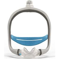
The Lumis™ HFT is a humidifier with an integrated flow generator that delivers warmed and humidified respiratory gases to spontaneously breathing patients through a nasal cannula.

WARNING
- Read this entire guide before using the device.
- Use the device according to the intended use provided in this guide.
- The advice provided by the prescribing physician should be followed ahead of the information provided in this guide.
- This device is not suitable for life support patients.
Indications for use
The Lumis HFT device is for the treatment of non-acute spontaneously breathing patients who would benefit from receiving high flow warmed and humidified respiratory gases. The flow may be from
15-40 L/min.
The Lumis HFT is for patients > 30 kg.
The humidifier is intended for single patient use in the home environment and re-use in a hospital/institutional environment.
Intended patient population/medical conditions
Obstructive pulmonary diseases (eg, Chronic Obstructive Pulmonary Disease) and chronic cough with mucous production (bronchiectasis).
Contraindications
High flow therapy may be contraindicated in some patients with the following pre-existing conditions:
- patients with a level of acuity that would experience injury from loss of therapy (e.g. acute respiratory failure, acute respiratory distress associated with COVID-19)
- blocked nasal passages/choanal atresia
• trauma/surgery to nasopharynx - invasive use.
Adverse effects
You should report unusual chest pain, severe headache, or increased breathlessness to your prescribing physician. An acute upper respiratory tract infection may require temporary discontinuation of treatment.
The following side effects may arise during the course of therapy with the device:
- nosebleed
- bloating
- skin rashes.
• drying of the nose, mouth or throat
At a glance
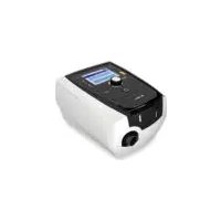
The Lumis HFT includes the following:
- Device
- HumidAir ^TM humidifier
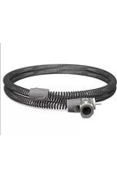
• ClimateLineAir ^TM heated air tubing - Tubing wrap
• Low Pressure Oxygen connector - Power supply unit
- Travel bag
• SD card (already inserted).
Contact your care provider for a range of accessories or accessory replacements available for use with the device including:
• HumidAir humidifier
• ClimateLineAir heated air tubing
• Filter: Hypoallergenic filter, standard filter
• Air10 ^TM DC/DC converter (12V/24V)
- SD card reader
• Air10 oximeter adapter
- Air10 USB adapter
- Power Station II
About your device
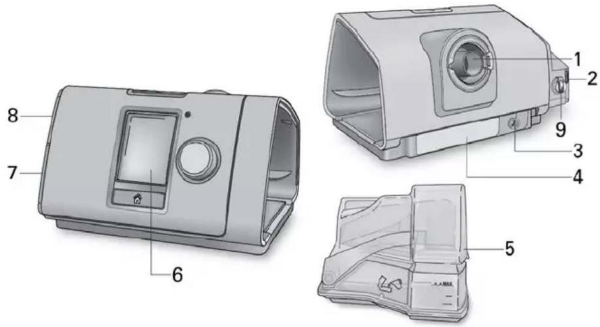
1 Air outlet 6 Screen
2 Air filter cover
7 Adapter cover
3 Power inlet 8 SD card cover
4 Serial number and device number
9 Low flow oxygen input (up to 15 L/min)
5 HumidAir humidifier
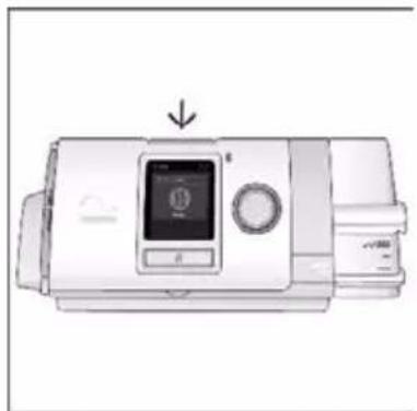
About the control panel

Start/Stop button
Press to start/stop therapy.
Press and hold for three seconds to enter power save mode.
Dial
Turn to navigate the menu and press to select an option. Turn to adjust a selected option and press to save your change.

Home button Press to return to the Home screen.
Different icons may be displayed on the screen at different times including:

Humidity

Wireless signal strength (green)

Humidifier warming

Wireless transfer not enabled (grey)

Humidifier not enabled

No wireless connection

Tube drying

Airplane Mode
Setup
natural_image
Diagram showing connections between a device with cables and a power strip, no text or symbols present
natural_image
Illustration of a coiled medical device with a bulb and connector, labeled with number 2 (no text or symbols on the device itself)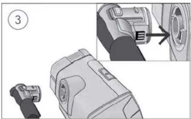
natural_image
Technical illustration of a device component with an inset showing a close-up view of the internal structure (no text or symbols present)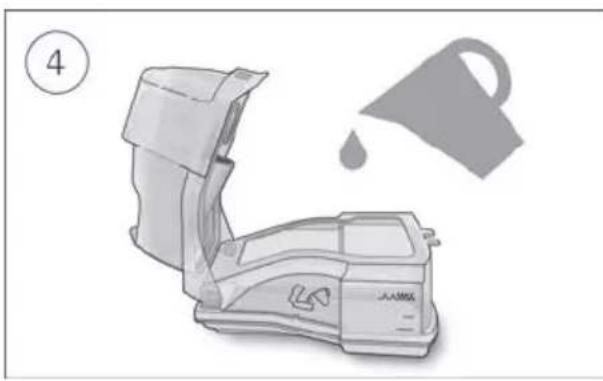
natural_image
Illustration of a washing machine with a drop symbol and a teapot nearby (no text or symbols)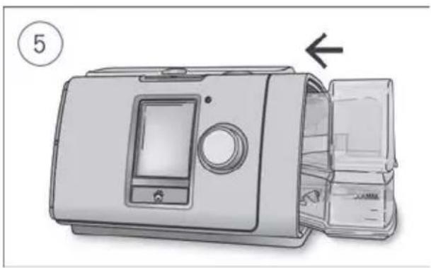
natural_image
Illustration of a device with an arrow pointing to a closed lid (no text or symbols present)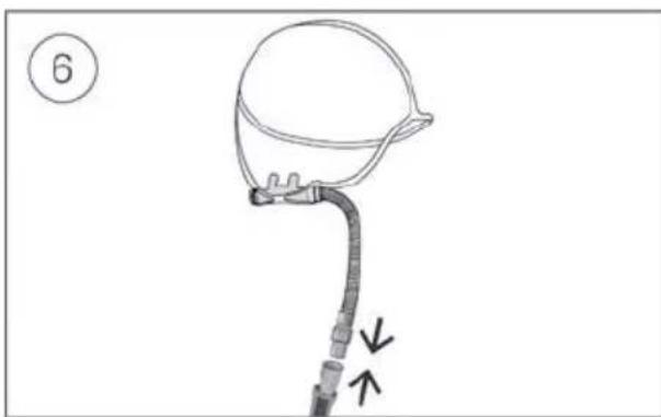
natural_image
Line drawing of a medical device with a bulb and tubing, no text or symbols presentCAUTION
• Only use nasal cannula with Lumis HFT, do not use full face masks.
• Do not overfill the humidifier as water may enter the device and air tubing.
• To avoid heated water flowing down the tube to the patient:
-
place the device lower than the level of the patient's head;
o ensure the device is placed on a stable surface. -
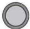
With the device on a stable level surface below head height, connect one end of the power cord into the power supply unit and the other end into the power outlet.
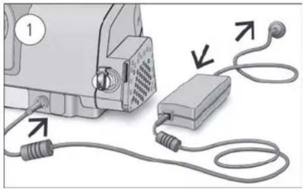
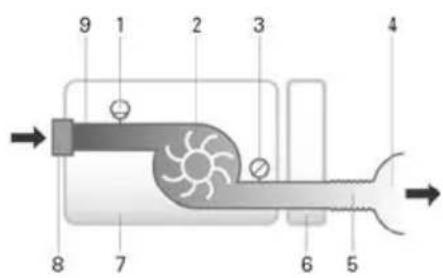
- Fit the tubing wrap around the air tubing. See the tubing wrap user guide for detailed information. Humidification performance will be reduced if the tubing wrap is not fitted.
- Connect the air tubing firmly to the air outlet located on the rear of the device.
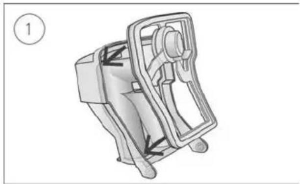
- Open the humidifier and fill it with water up to the maximum water level mark. Do not fill the humidifier with hot water.
-
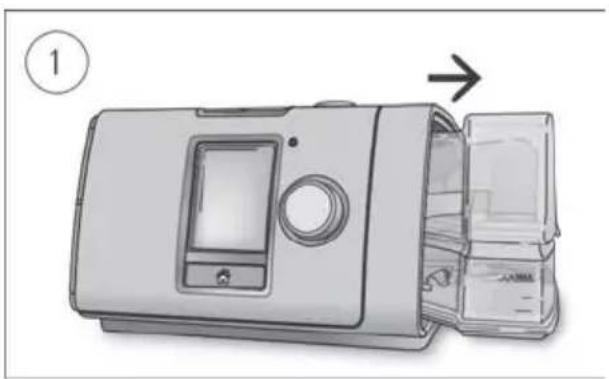
Close the humidifier and insert it into the side of the device.
-
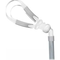
Connect the free end of the air tubing firmly onto the nasal cannula. See the nasal cannula user guide for detailed information.
Recommended nasal cannulas are available on ResMed.com/support.
Recommended water type
The following water types are recommended for use in the humidifier:
- Boiled tap water, cooled to room temperature
- Distilled water
- Bottled water (with a low mineral content).
Note: Do not use non-sterile demineralised water for domestic use.
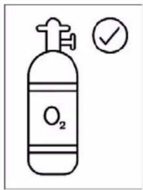
Adding supplemental oxygen
Your Lumis HFT device is designed to be compatible with levels of supplemental oxygen up to 15 L/min.

WARNING
- Always make sure that the device is turned on and airflow generated before the oxygen supply is turned on. Always turn the oxygen supply off before the device is turned off, so that unused oxygen does not accumulate within the device enclosure and create a risk of fire.
- Supplemental oxygen must only be added into your device oxygen inlet at the rear of the device. Adding oxygen elsewhere, ie, into the breathing system via tube, will affect the delivered flow volume, temperature, and humidity.
- Open flames or smoking during oxygen therapy is dangerous and likely to result in fire, facial burns, or death. Do not allow smoking or open flames within 7 ft (2 m) of the device or any oxygen-carrying accessories.
- When intending to smoke, turn the device off, remove the cannula, and leave the room where the cannula or device is located. If unable to leave the room, wait 10 minutes after the device has been turned off before smoking.

CAUTION
Do not connect supplemental oxygen input directly to a medical gas pipeline system, oxygen bottle or other high-pressure oxygen source. A flow regulator must be fitted to ensure the delivered oxygen remains at or below 15 L/min.
For advice on connecting to an oxygen source, contact your homecare provider.
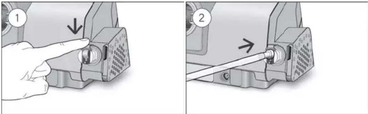
To add supplemental oxygen:
- Unlock the low flow oxygen input at the rear of the device by pushing down on the locking clip.
- Insert one end of the oxygen supply tubing into the low flow oxygen input. The tubing will automatically lock into place.
- Attach the other end of the oxygen supply tubing to the oxygen supply.
- Start therapy.
- Turn on oxygen and adjust (at the oxygen supply) to the prescribed flow rate.
To remove supplemental oxygen:
- Unlock the low flow oxygen input at the rear of the device by pushing down on the locking clip.
- Remove the oxygen port connector from the low flow oxygen input.

natural_image
Two-step diagram showing a hand operating a cable to a motor, with arrows indicating direction of movement (no text or symbols present)Performing a functional check
With the device powered off:
- Check the condition of the device and accessories.
Inspect the device and all the provided accessories. If there are any visible defects, the system should not be used. - Check the air tubing setup.
Check the integrity of the air tubing. Connect the air tubing firmly to the air outlet and other accessories if in use. - Check the connection to the oxygen port.
Inspect the connection for cracks or leaks and that the port is stable. - Check the HumidAir humidifier.
Inspect the humidifier for cracks or leaks. If there are any visible defects, the humidifier should be replaced.
Starting therapy
Warmup mode
Warmup mode pre-heats the water before starting therapy so that the air is not cold or dry at the start of therapy. It is recommended that Warmup mode be run before starting therapy.
Depending on the ambient conditions, the Lumis HFT device will take between 10 to 20 minutes to warm up. Therapy can be started any time during Warmup mode. After Warmup mode has been running for 40 minutes, the device will automatically switch to Drying mode.
To run warmup mode:

- Select Run Warmup.
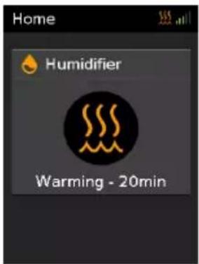
- Warmup will take between 10-20 mins. Therapy can be started at any time during Warmup.
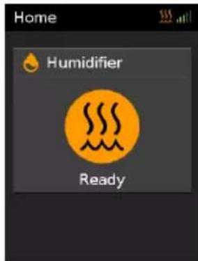
- When Warmup is complete, Ready will be displayed.
Start therapy
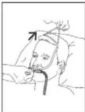
natural_image
Line drawing of a person receiving medical or surgical pressure from a cup (no text or symbols)- Fit your high-flow nasal cannula. See your nasal cannula user guide for fitting instructions.
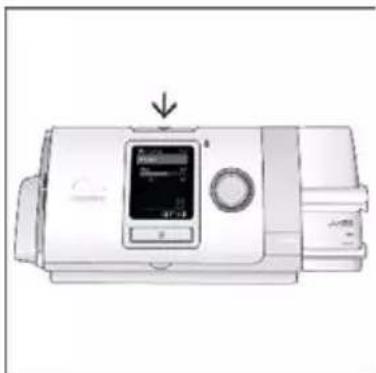
natural_image
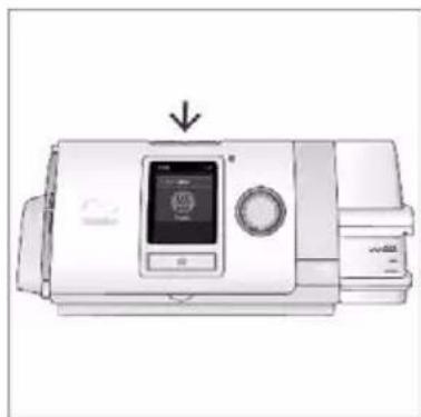
Illustration of a medical device with a digital display and control panel (no text or symbols visible)- Press the Start/Stop button to start therapy.
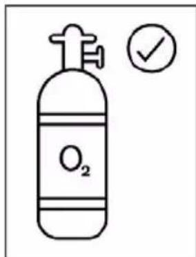
- If you have supplemental oxygen, ensure source is now turned ON.
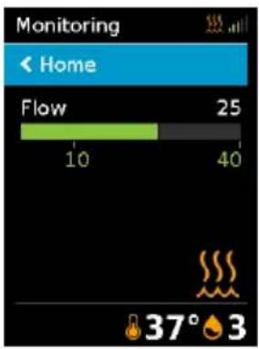
You will know that therapy is on when the Monitoring screen is displayed. The FLOW bar shows the current flow setting in green.
The screen will go black automatically after a short period of time. You can press Home or the dial to turn it back on. If power is interrupted during therapy, the device will automatically restart therapy when power is restored.
The Lumis HFT device has a light sensor that adjusts the screen brightness based on the light in the room.
Note: Consider placing device on heat resistant pad to avoid possible heat damage to surfaces.
Expected duration of operation between refills
Flow Setting vs therapy duration*
| L/min | 15 | 20 | 25 | 30 | 35 | 40 |
| hrs | 16 | 12 | 10 | 9 | 8 | 7 |
Tested at Humidity - Level 3, tube temperature 37°C, and ambient temperature 23°C
Stopping therapy
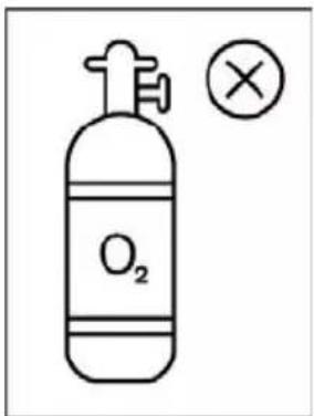
- Ensure oxygen source is turned OFF.

natural_image
Line drawing of a person lying in bed with a medical device attached, showing no text or symbols- Remove your high-flow nasal cannula.
natural_image
Illustration of a portable electronic device with a digital display and control buttons (no text or symbols visible)- Press the Start/Stop button and then press the dial to confirm Yes to stop therapy.
Drying mode

After stopping therapy, Drying mode will automatically start. This mode dries the air tube and cannula so that it is ready for use next time.
During Drying mode, do not remove the humidifier water tub. The device will automatically enter standby after 90 minutes.
While Drying mode is running you can view the Therapy Report by pressing the Home button.
The device regulates the tube temperature to a medium value, whilst running the humidifier at minimum power during the Drying mode.
WARNING
- Remove the nasal cannula from your face before starting Drying mode because the air is dry and may cause harm.
- Turn off supplemental oxygen at the source before starting Drying mode so that oxygen does not accumulate and create a fire risk.
Power save mode
Your Lumis HFT device records your therapy data. In order to allow it to transmit the data to your care provider, you should not unplug the device. However, you can put it into power save mode to save electricity.
To enter power save mode:
- Press and hold Start/Stop for three seconds. The screen goes black.
To exit power save mode:
- Press Start/Stop once. The Home screen is displayed.
My Options
Your Lumis HFT device has been set up for your needs by your care provider, but you may find you want to make small adjustments to make your therapy more comfortable.
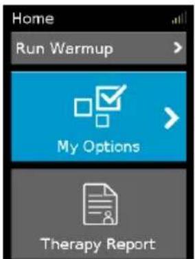
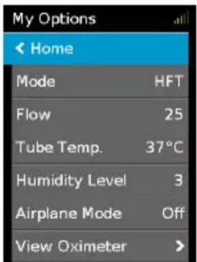
Highlight My Options and press the dial to see your current settings. From here, you can personalise your options.
Flow
The flow selected for the patient should be based on that prescribed by the clinician. The Lumis HFT device is designed to deliver flows between 15 L/min and 40 L/min.
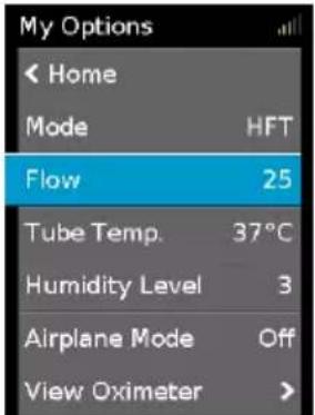
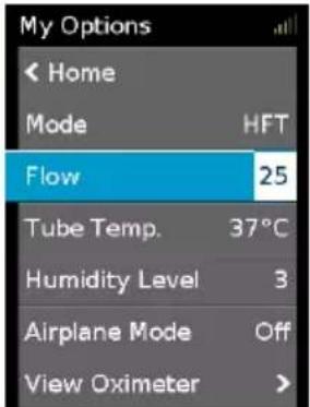
To adjust the Flow rate:
-
In My Options, turn the dial to highlight Flow and then press the dial.
-
Turn the dial to adjust the flow rate and press the dial to save the change.
Tube Temperature
The ClimateLineAir heated air tubing is designed to deliver consistent, comfortable temperature during therapy. The default setting of 37^ matches normal body temperature and maintains a relative humidity level while protecting against moisture in the air tubing and cannula (rainout).
If you find the air is too warm, you can reduce the temperature in the air tubing.
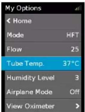
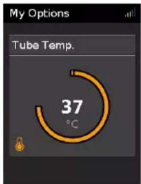
To adjust the Tube Temperature.
-
In My Options, turn the dial to highlight Tube Temp and then press the dial.
-
Turn the dial to adjust the temperature level and press the dial to save the change.
Humidity Level
The humidifier moistens the air and is designed to make therapy more comfortable. If you are getting a dry nose or mouth, turn up the humidity. If you are getting any moisture in your nasal cannula, turn down the humidity.
You can set the Humidity Level between 1 and 5, where 1 is the lowest humidity setting and 5 is the highest humidity setting.
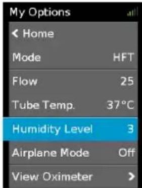

To adjust the Humidity Level:
-
In My Options, turn the dial to highlight Humidity Level and then press the dial.
-
Turn the dial to adjust the humidity level and press the dial to save the change.
Therapy Report

Once therapy has stopped, the Therapy Report gives you a summary of your therapy session.
Usage hours—Indicates the number of hours of therapy you received last session.
Caring for your device
It is important that you regularly clean your Lumis HFT device to make sure you receive optimal therapy. The following sections will help you with disassembling, cleaning, checking and reassembling your device.
WARNING
Regularly clean your tubing assembly, humidifier and nasal cannula to receive optimal therapy and to prevent the growth of germs that can adversely affect your health.
CAUTION
Regularly remove tubing wrap to allow proper inspection of the air tubing for dirt or damage.
Disassembling
natural_image
Illustration of a device with an open lid and internal compartments, showing a numbered step (1) and an arrow indicating direction (no text or symbols on the device itself)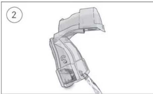
natural_image
Illustration of a mechanical device with a handle and water pouring (no text or symbols)
natural_image
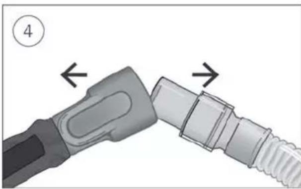
Close-up of a mechanical connector with two arrows indicating assembly or movement (no text or symbols)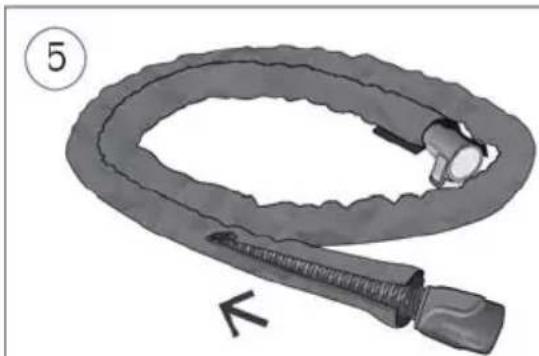
natural_image
Illustration of a coiled medical or mechanical device with a bulb and connector (no text or symbols)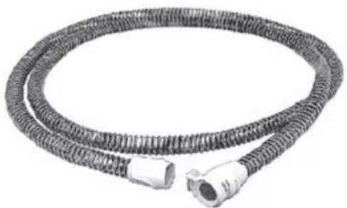
natural_image
Coiled industrial hose with connectors (no text or symbols visible)- Hold the humidifier at the top and bottom, press it gently and pull it away from the device.
- Open the humidifier and discard any remaining water.
-
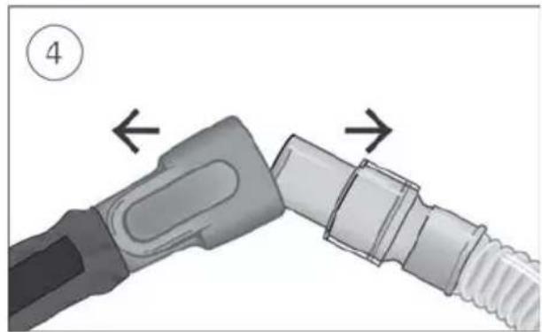
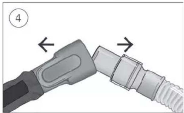
Hold the cuff of the air tubing, apply gentle pressure to the release buttons and pull it away from the device.
-
Hold both the cuff of the air tubing and nasal cannula, then gently pull apart.
-
Remove the tubing wrap to allow proper inspection of the air tubing for dirt or damage.
Cleaning
You should clean the device weekly as described. Refer to the nasal cannula user guide for detailed instructions on cleaning the nasal cannula.
-
Wash the humidifier and air tubing in warm water using mild detergent.
-
Wash the tubing wrap in cold to warm water using a mild detergent. Rinse well and drip dry.
-
Rinse the humidifier and air tubing thoroughly and allow to dry out of direct sunlight and/or heat.
-
Wipe the exterior of the device with a dry cloth.
Notes:
- Empty the humidifier daily and wipe it thoroughly with a clean, disposable cloth. Allow to dry out of direct sunlight and/or heat.
- The humidifier may be washed in a dishwasher on the delicate or glassware cycle (top shelf only). It should not be washed at temperatures higher than 65°C.
- The tubing wrap should be hand washed or dry cleaned only. Hand washing your tubing wrap does not replace the need to clean your air tubing.
- Do not wash the air tubing in a dishwasher or washing machine.
Checking
You should regularly check the humidifier, air tubing and the air filter for any damage.
- Replace it if it is leaking or has become cracked, cloudy or pitted.
- Replace it if the seal is cracked or torn.
- Remove any white powder deposits using a solution of one-part household vinegar to 10 parts water.
-
Remove the tubing wrap and check the air tubing is clean and replace it if there are any holes, tears or cracks.
-
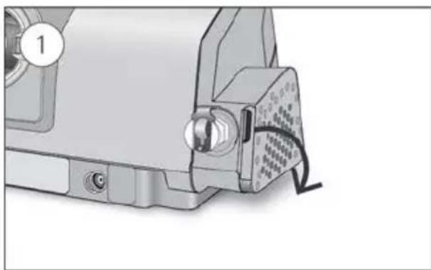
Check the air filter and replace it at least every six months. Replace more often if there are any holes or blockages by dirt or dust.
To replace the air filter:
natural_image
Mechanical component with a clamped connector and labeled part (1), showing no visible text or symbols.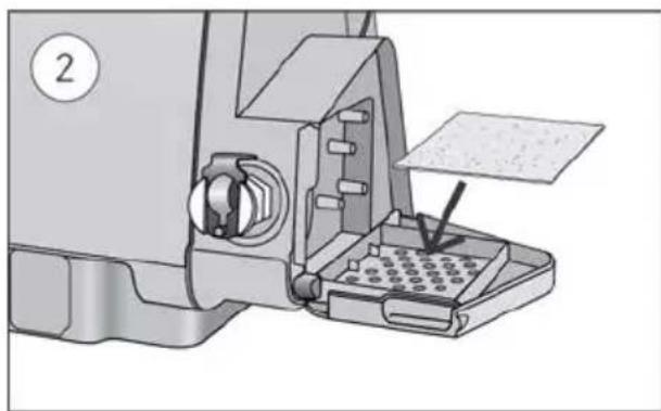
natural_image
Mechanical assembly diagram showing a sewing machine with a baseplate and tool inserted (no text or symbols visible)- Open the air filter cover and remove the old air filter.
The air filter is not washable or reusable.
- Place a new air filter onto the air filter cover and then close it.
Make sure the air filter is fitted at all times to prevent water and dust from entering the device.
Reassembling
When the humidifier and air tubing are dry, you can reassemble the parts.
- Connect the air tubing firmly to the air outlet located on the rear of the device.
- Open the humidifier and fill it with room temperature water up to the maximum water level mark.
- Close the humidifier and insert it into the side of the device.
- Connect the free end of the air tubing firmly onto the nasal cannula.
Therapy data
Your Lumis HFT device records your therapy data for you and your care provider so they can view and make changes to your therapy if required. The data is recorded and then transferred to your care provider wirelessly, if a wireless network is available, or via an SD card.
Data transmission
Your Lumis HFT device has the capability of wireless communication so that your therapy data can be transmitted to your care provider to improve the quality of your treatment. This is an optional feature that will only be available if you choose to benefit from it and if a wireless network is available. It also allows your care provider to update your therapy settings in a more timely manner or upgrade your device software to ensure you receive the best therapy possible.
The data is usually transmitted after therapy has stopped. In order to make sure that your data is transferred, leave your device connected to the mains power at all times and make sure that it is not in Airplane Mode.
Notes:
• Therapy data might not be transmitted if you use it outside of the country or region of purchase.
• Wireless communication depends on network availability.
• Devices with wireless communication might not be available in all regions.
SD card
An alternative way for your therapy data to be transferred to your care provider is via the SD card. Your care provider may ask you to send the SD card by mail or to bring it in. When instructed by your care provider, remove the SD card.
Do not remove the SD card from the device when the SD light is flashing because data is being written to the card.
To remove the SD card:
natural_image
Illustration of a microwave oven with a perforated lid and a control panel, showing no text or symbols.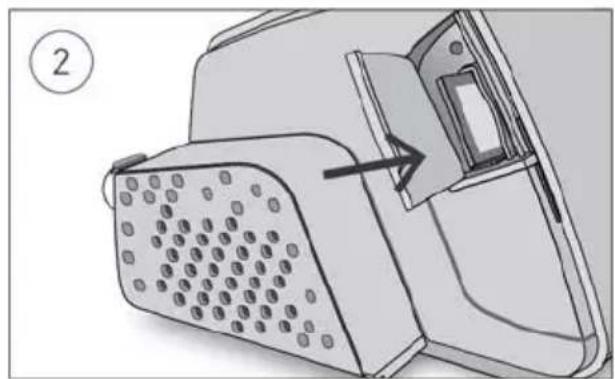
natural_image
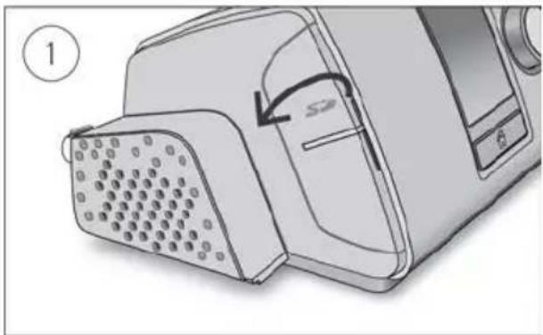
Diagram of a device with a grid-patterned panel and an arrow pointing to a component (no text or symbols present)- Open the SD card cover.
- Push in the SD card to release it. Remove the SD card from the device. Place the SD card in the protective folder and send it back to your care provider.
For more information on the SD card refer to the SD card protective folder provided with your device.
Note: The SD card should not be used for any other purpose.
Travelling
You can take your Lumis HFT device with you wherever you go. Just keep the following in mind:
- Use the travel bag provided to prevent damage to the device.
• Empty the humidifier before packing it in the travel bag. - Make sure you have the appropriate power cord for the region you are travelling to. For information on purchasing, contact your care provider.

CAUTION
Do not use the device while in transit (eg, on a plane, car, wheelchair) due to the risk of water spilling into the device or inhalation of water.
Troubleshooting
If you have any problems, have a look at the following troubleshooting topics. If you are not able to fix the problem, contact your care provider or ResMed. Do not try to open the device.
General troubleshooting
| Problem/possible cause | Solution |
| I am getting a dry or blocked nose | |
| Humidity level may be set too low. | Adjust the Humidity Level. |
| I am getting droplets of water in the nasal cannula and air tubing | |
| Humidity level may be set too high. | Adjust the Humidity Level. |
| Tubing wrap not in use. | Fit tubing wrap.See the tubing wrap user guide for fitting instructions. |
| Air flow in my nose seems too high (it feels like I am getting too much air) | |
| Flow may be set too high. | Talk to your care provider about your settings. |
| Air flow in my nose seems too low (it feels like I am not getting enough air) | |
| Flow may be set too low. | Talk to your care provider about your settings. |
| My screen is black | |
| Backlight on the screen may have turned off. It turns off automatically after a short period of time. | Press Home or the dial to turn it back on. |
| Power may not be connected. | Connect the power supply and make sure the plug is fully inserted. |
| I have stopped therapy, but the device is still blowing air | |
| Device is drying circuit and nasal cannula. | Device blows a small amount of air in order to dry the air tubing and nasal cannula. It will stop automatically after 90 minutes. |
| My humidifier is leaking | |
| Humidifier may not be assembled correctly. | Check for damage and reassemble the humidifier correctly. |
| Humidifier may be damaged or cracked. | Contact your care provider for a replacement. |
| My therapy data has not been sent to my care provider | |
| Power may not be connected. | Connect the power supply and make sure the plug is fully inserted. |
| Wireless coverage may be poor. | Make sure that the device is placed where there is coverage (ie, on your bedside table, not in a drawer or on the floor). The Wireless signal strength icon indicates good coverage when all bars are displayed, and poor coverage when fewer bars are displayed. |
| The No wireless connection icon is displayed on the top right of the screen. no wireless network available. | Make sure that the device is placed where there is coverage (ie, on your bedside table, not in a drawer or on the floor). If instructed to do so, send the SD card to your care provider. The SD card also contains your therapy data. |
| Device may be in Airplane Mode. | Turn off Airplane Mode. |
| Data transfer is not enabled for your device. | Talk to your care provider about your settings. |
| My screen and buttons are flashing but there is no alarm sound or message | |
| Software upgrade is in progress. | Software upgrade takes approximately 10 minutes to complete. |
| Air tubing may not be connected. | Check the air tubing is connected to the device. |
| Displays message: Read only card, please remove, unlock and re-insert SD card | |
| SD card switch may be in the lock (read-only) position. | Move the switch on the SD Card from the lock position to the unlock position and then re-insert it. |
Alert troubleshooting
| Problem/possible cause | Solution |
| Displays message: Therapy will not run without a humidifier tub or heated tube | |
| End cap is installed in place of humidifier. | Remove the end cap and attach the humidifier. |
| Humidifier may not be inserted properly. | Make sure the humidifier is correctly inserted. |
| Non-heated air tubing attached. | Attach the ClimateLineAir heated air tubing. |
| Displays message: Humidifier tub empty. Therapy has stopped | |
| Humidifier tub is empty. | Refill the humidifier to resume therapy. |
| Displays message: High leak detected, check your water tub or tub seal | |
| Humidifier may not be inserted properly. | Make sure the humidifier is correctly inserted. |
| Humidifier seal may not be inserted properly. | Open the humidifier and make sure that the seal is correctly inserted. |
| Displays message: High leak detected, connect your tubing | |
| Air tubing may not be connected properly. | Make sure the air tubing is firmly connected at both ends. Remove tubing wrap and check the air tubing and replace it if there are any holes, tears or cracks. |
| Displays message: Tubing blocked, check your tubing | |
| Air tubing may be blocked. | Check the air tubing and remove any blockages. Press the dial to clear the message and then press Start/Stop to restart the device. |
| Displays message: No SpO_2 data, check your oxi sensor attachment to module/finger | |
| Oximeter sensor is not attached properly. | Ensure that the oximeter sensor is attached properly to the module and to your finger. |
| Oximeter sensor may be faulty. | If the message appears repeatedly, the oximeter sensor might be faulty. Replace the oximeter. |
| Displays message: System fault, refer to user guide, Error 004 | |
| Device may have been left in a hot environment. | Allow to cool before re-use. Disconnect the power supply and then reconnect it to restart the device. |
| Air filter may be blocked. | Check the air filter and replace it if there are any blockages. Disconnect the power supply and then reconnect it to restart the device. |
| Air tubing may be blocked. | Check the air tubing and remove any blockages. Press the dial to clear the message and then press Start/Stop to restart the device. |
| There may be water in the air tubing. | Empty the water from the air tubing. Disconnect the power supply and then reconnect it to restart the device. |
| Displays message: System fault, refer to user guide, Error 022 | |
| Power cord may not be correctly inserted into the device. | Remove the power cord from the device and then re-insert it. Ensure that the power cord is fully inserted into the device. If the problem continues, contact your local ResMed dealer or ResMed office. Do not open the device. |
| All other error messages, for example, System fault, refer to user guide, Error 0XX | |
| An unrecoverable error has occurred on the device. | Contact your care provider. Do not open the device. |
Reassembling parts
Some parts of your device are designed to easily come off in order to avoid damage to the parts or the device. You can easily reassemble them as described below.
To insert the humidifier seal:
natural_image
Technical line drawing of a mechanical component with directional arrows indicating movement (no text or symbols)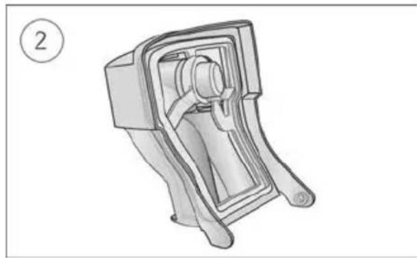
natural_image
Technical line drawing of a mechanical device with no visible text or symbols- Place the seal into the lid.
- Press down along all edges of the seal until it is firmly in place.
To reassemble the humidifier lid:
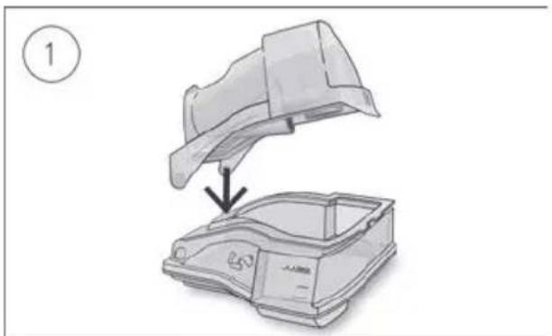
natural_image
Diagram showing a car body being lifted by an umbrella, with no text or symbols present.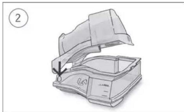
natural_image
Diagram of a portable radio device with an open lid and internal casing, showing a handle and base (no text or symbols)- Insert one side of the lid into the pivot hole of the base.
- Slide the other side down the ridge until it clicks into place.
General warnings and cautions
WARNING
• Make sure that you arrange the air tubing so that it will not twist around the head or neck.
- Regularly inspect power cords, cables, and power supply for damage or signs of wear. Discontinue use and replace if damaged.
- Keep the power cord away from hot surfaces.
- If you notice any unexplained changes in the performance of the device, if it is making unusual sounds, if the device or the power supply are dropped or mishandled, or if the enclosure is broken, discontinue use and contact your care provider or your ResMed Service Centre.
- Do not open or modify the device. There are no user serviceable parts inside. Repairs and servicing should only be performed by an authorised ResMed service agent.
- Beware of electrocution. Do not immerse the device, power supply or power cord in water. If liquids are spilled into or onto the device, unplug the device and let the parts dry. Always unplug the device before cleaning and make sure that all parts are dry before plugging it back in.
- Do not perform any maintenance tasks while the device is in operation.
- The device should not be used adjacent to or stacked with other equipment. If adjacent or stacked use is necessary, the device should be observed to verify normal operation in the configuration in which it will be used.
- The use of accessories other than those specified for the device is not recommended. They may result in increased emissions or decreased immunity of the device.
- The device has not been tested or certified for use in the vicinity of X-ray, CT or MRI equipment. Do not bring the device within 4 m of X-ray or CT equipment. Never bring the device into an MR environment.
• Therapy settings should not be changed remotely for patients in a hospital setting. - Do not use the device outside its approved operating conditions. Using the device above an altitude of 2,591m and/or outside the temperature range of 18°C to 28°C, may reduce the effectiveness of treatment and/or damage the device.
- Connecting the device to the battery of a battery-powered wheelchair may affect the device performance and may result in patient harm.
- Use only water-based lotions or salves that are oxygen-compatible before and during oxygen therapy. Do not use petroleum-based or oil-based lotions or salves to avoid the risk of fire and burns.
- Do not lubricate fittings, connections, tubing, or other accessories of the equipment to avoid the risk of fire and burns.

CAUTION
- Use only ResMed (or ResMed recommended) parts and accessories with the device. Parts not recommended by ResMed may reduce the effectiveness of the treatment and/or damage the device.
- Use only nasal cannulas recommended by ResMed or by the prescribing doctor with this device.
- Be careful not to place the device where it can be bumped or where someone is likely to trip over the power cord.
- Keep the area around the device dry, clean and clear of anything (eg, clothes or bedding) that could block the air tubing, inlet, or cover the device and/or power supply unit while in operation, as this could lead to overheating of the device.
- Do not place the device on its side as water might get into the device.
- Do not use bleach, chlorine, alcohol, or aromatic-based solutions, moisturising or antibacterial soaps or scented oils to clean the device, the humidifier or air tubing. These solutions may cause damage or affect the humidifier performance and reduce the life of the products. Exposure to smoke, including cigarette, cigar or pipe smoke, as well as ozone or other gases, may damage the device. Damage caused by any of the foregoing will not be covered by ResMed's limited warranty.
- Leave the humidifier to cool for ten minutes before handling to allow the water to cool and to make sure that the humidifier is not too hot to touch.
- Make sure that the humidifier is empty before transporting the device.
- Avoid placing the device directly on varnished surfaces during operation, as heat build-up may damage the finish.
Notes:
- The device is not intended to be operated by persons (including children) with reduced physical, sensory or mental capabilities without adequate supervision by a person responsible for the patient's safety.
- For any serious incidents that occur in relation to this device, these should be reported to ResMed and the competent authority in your country.
Technical specifications
Units are expressed in cm H_2O and hPa. 1 cm H_2O is equal to 0.98 hPa.
| 90W power supply unit | |
| AC input range: | 100–240V, 50–60Hz 1.0–1.5A, Class II115V, 400Hz 1.5A, Class II (nominal for aircraft use) |
| DC output: | 24V --- 3.75A |
| Typical power consumption: | 53W (57VA) |
| Peak power consumption: | 104W (108VA) |
| Environmental conditions | |
| Operating temperature: | +18°C to +28°CNote: The air flow for breathing produced by this therapy device can be higher than the temperature of the room.Under extreme ambient temperature conditions (40°C) the device remains safe. |
| Operating humidity: | 15 to 95% relative humidity, non-condensing |
| Operating altitude: | Sea level to 2,591 m; air pressure range 1013 hPa to 738 hPaTherapy performance may be reduced at high altitudes with some nasal cannulas. Refer to the Nasal Cannula Device Compatibility Guide for details. |
| Storage and transport temperature: | -20°C to +60°C |
| Storage and transport humidity: | 5 to 95% relative humidity, non-condensing |
| Humidifier classification: ISO 80601-2-74:2017 | |
| Category 2 – non-invasive, nasal high flow therapy | |
| Electromagnetic compatibility | |
| The Lumis HFT complies with all applicable electromagnetic compatibility requirements (EMC) according to IEC 60601-1-2:2014, for residential, commercial and light industry environments. It is recommended that mobile communication devices are kept at least 1 m away from the device.Information regarding the electromagnetic emissions and immunity of this ResMed device can be found on www.resmed.com/downloads/devices | |
| Classification: EN60601-1:2006/A1:2013Class II (double insulation), Type BF, Ingress protection IP22. | |
| Sensors | |
| Pressure sensors: | Internally located at device outlet, analogue gauge pressure type, 0 to 40 cm H_2O (0 to 40 hPa) |
| Flow sensor: | Internally located at device inlet, digital mass flow type, -70 to +180 L/min |
| Operating flow range | 15 – 40 L/min |
| Humidifier output | >12 mg/L BTPS |
| Maximum operating pressure | 25 cm H_2O (25 hPa) |
| Maximum single fault steady pressure | |
| Device will shut down in the presence of a single fault if the steady state pressure exceeds:30 cm H_2O (30 hPa) for more than 6 sec or 40 cm H_2O (40 hPa) for more than 1 sec. | |
Sound
Pressure level measured according to ISO 80601-2-74:2017 (HFT mode):
| ClimateLineAir: | 38 dBA with uncertainty of 2 dBA |
| ClimateLineAir and 5 L/min supplemental oxygen: | 39 dBA with uncertainty of 2 dBA |
| ClimateLineAir and 10 L/min supplemental oxygen: | 46 dBA with uncertainty of 2 dBA |
| ClimateLineAir and 15 L/min supplemental oxygen: | 51 dBA with uncertainty of 2 dBA* |
| *Tested value may not comply to ISO 80601-2-74:2017 due to measurement uncertainty | |
Physical - device and humidifier
| Dimensions (H x W x D): | 116 mm x 265 mm x 150 mm |
| Air outlet (complies with ISO 5356-1:2015): | 22 mm |
| Weight (device and cleanable humidifier): | 1290 g |
| Housing construction: | Flame retardant engineering thermoplastic |
| Water capacity: | To maximum fill line 380 mL |
| Cleanable humidifier - material: | Injection moulded plastic, stainless steel and silicone seal |
Temperature
Maximum heater plate: 76°C
| Cut-out: | 78°C |
| Maximum gas temperature: | ≤43°C |
Air filter
| Standard: | Material: Polyester non-woven fibreAverage arrestance: >75% for ~7 micron dust |
| Hypoallergenic: | Material: Acrylic and polypropylene fibres in a polypropylene carrierEfficiency: >98% for ~7-8 micron dust; >80% for ~0.5 micron dust |
Wireless module
Technology used: 4G (LTE)
It is recommended that the device is a minimum distance of 2 cm from the body during operation. Not applicable to masks, tubes or accessories. Technology may not be available in all regions.
Declaration of Conformity (DoC to the Radio Equipment Directive)

ResMed declares that the Lumis HFT device (models 285xx) is in compliance with the essential requirements and other relevant provisions of Directive 2014/53/EU (RED). A copy of the Declaration of Conformity (DoC) can be found on Resmed.com/productsupport
This device can be used in all European countries without any restrictions.
All ResMed devices are classified as medical devices under the Medical Device Directive. Any labelling of the product and printed material, showing CE0123, relates to the Council Directive 93/42/EEC including the Medical Device Directive amendment (2007/47/EC).
Supplemental oxygen
| Maximum flow: | 15 L/min |
| Device air leak at 25 cmH2O: | ≤ 2L/min |
Pneumatic flow path
- Flow sensor
- Blower
- Pressure sensor
- Nasal cannula
- Air tubing
- Humidifier
- Device
- Inlet filter
- Low flow oxygen input (up to 15 L/min)
Design life
| Device, power supply unit: | 3 years |
| Cleanable humidifier tub: | 3 months |
| Air tubing: | 6 months |
General
The patient is an intended operator.
Operator position
The device is designed to be operated within arm's length. An operator should position their line of sight within an angle of 30 degrees from a plane perpendicular to the screen.
Air tubing
| Air tubing | Material | Length | Inner diameter |
| ClimateLineAir | Flexible plastic and electrical components | 2 m | 15 mm |
| Heated air tubing temperature cut-out: ≤ 43°C | |||
Notes:
- The manufacturer reserves the right to change these specifications without notice.
- The electrical connector end of the heated air tubing is only compatible with the air outlet at the device end and should not be fitted to the nasal cannula.
- Do not use electrically conductive or antistatic air tubing.
- The temperature and relative humidity settings displayed are not measured values.
Displayed values
| Value | Accuracy ^1 |
| Flow | ±6 L/min at 0 to 40 L/min positive flow |
^1 Results are expressed as STPD (Standard Temperature and Pressure, Dry). (101.3kPa at an operating temperature of 20^ C, dry). Use the table below to convert the STPD flow setting to BTPS (Body Temperature and Pressure, Saturated) flow.
BTPS Flow (L/min)
| Altitude (m) | Target Flow Setting (L/min) | |||||
| 15 | 20 | 25 | 30 | 35 | 40 | |
| 0 | 17 | 23 | 28 | 34 | 39 | 45 |
| 500 | 18 | 24 | 30 | 36 | 42 | 48 |
| 1000 | 19 | 26 | 32 | 38 | 45 | 51 |
| 1500 | 20 | 27 | 34 | 41 | 48 | 54 |
| 2000 | 22 | 29 | 36 | 43 | 51 | 58 |
| 2500 | 23 | 31 | 38 | 46 | 54 | 62 |
Measurement system uncertainties
In accordance with ISO 80601-2-74:2017 the measurement uncertainty of the manufacturer's test equipment for measures of flow is ± 1.5L / min or ± 2.7% of reading (whichever is greater)
Guidance and manufacturer's declaration electromagnetic emissions and immunity
Medical electrical equipment needs special precautions regarding EMC and needs to be installed and put into service according to EMC information provided in this document.
The Lumis HFT device has been designed to meet EMC standards. However, should you suspect that the device performance (eg, pressure or flow) is affected by other equipment, move the device away from the possible cause of interference.
Guidance and manufacturer's declaration—electromagnetic emissions
The device is intended for use in the electromagnetic environment specified below. The customer or the user of the device should assure that the device is used in such an environment.
| Emissions test | Compliance | Electromagnetic environment — guidance |
| RF emissions CISPR 11 | Group 1 | The device uses RF energy only for its internal function. Therefore, its RF emissions are very low and are not likely to cause any interference in nearby electronic equipment. |
| RF emissions CISPR 11 | Class B | The device is suitable for use in all establishments, including domestic establishments and those directly connected to the public low-voltage network that supplies buildings used for domestic purposes. |
| Harmonic EmissionsIEC 61000-3-2 | Class A | |
| Voltage Fluctuations/Flicker EmissionsIEC 61000-3-3 | Complies |
Guidance and manufacturer's declaration – electromagnetic immunity
The device is intended for use in the electromagnetic environment specified below. The customer or the user of the device should assure that the device is used in such an environment.
^a Field strengths from fixed transmitters, such as base stations for radio (cellular/cordless) telephones and land mobile radios, amateur radio, AM and FM radio broadcast and TV broadcast cannot be predicted theoretically with accuracy. To assess the electromagnetic environment due to fixed RF transmitters, an electromagnetic site survey should be considered. If the measured field strength in the location in which the device is used exceeds the applicable RF compliance level above, the device should be observed to verify normal operation. If abnormal performance is observed, additional measures may be necessary, such as reorienting or relocating the device.
^b Over the frequency range 150 kHz to 80 MHz, field strengths should be less than 3 V/m.
| Immunity test | IEC60601-1-2 test level | Compliance level | Electromagnetic environment — guidance |
| Electrostatic discharge (ESD) IEC 61000-4-2 | ±6 kV contact ±8 kV air | ±8 kV contact ±15 kV air | Floors should be wood, concrete or ceramic tile. If floors are covered with synthetic material, the relative humidity should be at least 30%. |
| Electrical fast transient/burst IEC 61000-4-4 | ±2 kV for power supply lines ±1 kV for input/output lines | ±2 kV ±1 kV for input/output lines | Mains power quality should be that of a typical commercial or hospital environment. |
| Surge IEC 61000-4-5 | ±1 kV differential mode ±2 kV common mode | ±1 kV differential mode ±2 kV common mode | Mains power quality should be that of a typical commercial or hospital environment. |
| Voltage dips, short interruptions and voltage variations on power supply input lines IEC 61000-4-11 | <5% Ut (>95% dip in Ut) for 0.5 cycle 40% Ut (60% dip in Ut) for 5 cycles 70% Ut (30% dip in Ut) for 25 cycles <5% Ut (>95% dip in Ut) for 5 sec | 100V 240V | Mains power quality should be that of a typical commercial or hospital environment. If the user of the device requires continued operation during power mains interruptions, it is recommended that the device be powered from an uninterruptible power source. |
| Power frequency (50/60 Hz) magnetic field IEC 61000-4-8 | 3 A/m | 30 A/m | Power frequency magnetic fields should be at levels characteristic of a typical location in a typical commercial or hospital environment. |
| Conducted RF IEC 61000-4-6 | 3 Vrms150 kHz to 80 MHz | 3 Vrms150 kHz to 80 MHz | Portable and mobile RF communications equipment should be used no closer to any part of the device, including cables, than the recommended separation distance calculated from the equation applicable to the frequency of the transmitter. |
| Radiated RF IEC 61000-4-3 | 3 V/m80 MHz to 2.5 GHz | 10 V/m80 MHz to 2.5 GHz | Recommended separation distanced = 0.35 √Pd = 0.35 √P 80 MHz to 800 MHzd = 0.70 √P 800 MHz to 2.5 GHzWhere (P) is the maximum output power rating of the transmitter in watts (W) according to the transmitter manufacturer and d is the recommended separation distance in meters (m). Field strengths from fixed RF transmitters, as determined by an electromagnetic site survey, a should be less than the compliance level in each frequency range. b Interference may occur in the vicinity of equipment marked with the following symbol: [IMAGE] |
Notes:
- Ut is the AC mains voltage prior to application of the test level.
- At 80 MHz and 800 MHz, the higher frequency range applies.
- These guidelines may not apply in all situations. Electromagnetic propagation is affected by absorption and reflection from structures, objects and people.
Recommended separation distances between portable and mobile RF communications equipment and the device
The device is intended for use in an environment in which radiated RF disturbances are controlled. The customer or the user of the device can help prevent electromagnetic interference by maintaining a minimum distance between portable and mobile RF communications equipment (transmitters) and the device as recommended below, according to the maximum output power of the communications equipment.
| Rated maximum output power of transmitter (W) | Separation distance according to frequency of transmitter (m) | ||
| 150 kHz to 80 MHz d = 0.35 √P | 80 MHz to 800 MHz d = 0.35 √P | 800 MHz to 2.5 GHz d = 0.7 √P | |
| 0.01 | 0.035 | 0.035 | 0.070 |
| 0.1 | 0.11 | 0.11 | 0.22 |
| 1 0.35 0.35 0.70 | |||
| 10 | 1.1 | 1.1 | 2.2 |
| 100 | 3.5 | 3.5 | 7.0 |
For transmitters rated at a maximum output power not listed above, the recommended separation distance d in metres (m) can be determined using the equation applicable to the frequency of the transmitter, where P is the maximum output power rating of the transmitter in watts (W) according to the transmitter manufacturer.
Notes:
- At 80 MHz and 800 MHz, the separation distance for the higher frequency range applies.
- These guidelines may not apply in all situations. Electromagnetic propagation is affected by absorption and reflection from structures, objects and people.
Symbols
The following symbols may appear on the product or packaging.
Read instructions before use. Indicates a warning or caution. Follow instructions before use. Manufacturer. EC REP European Authorised Representative. LOT Batch code. REF Catalogue number. SN Serial number. DN Device number. On / Off. Device weight. IP22 Protected against finger sized objects and against dripping water when tilted up to 15 degrees from specified orientation. Direct current. Type BF applied part. Class II equipment. Humidity limitation. Temperature limitation. Non-ionising radiation. China pollution control logo 1. China pollution control logo 2. Rx Only Prescription only (In the US, Federal law restricts these devices to sale by or on the order of a physician). MAX Maximum water level. Distilled Water Only Use distilled water only. Operating altitude. Atmospheric pressure limitation. Complies with RTCA DO-160 section 21, category M. MR unsafe (do not use in the vicinity of an MRI device). Oxygen supply inlet connector. Date of manufacture. Alarm inhibit (Low SpO2 alarm is not available). Importer. Medical device.
See symbols glossary at ResMed.com/symbols.

Environmental information
This device should be disposed of separately, not as unsorted municipal waste. To dispose of your device, you should use appropriate collection, reuse and recycling systems available in your region. The use of these collection, reuse and recycling systems is designed to reduce pressure on natural resources and prevent hazardous substances from damaging the environment.
If you need information on these disposal systems, please contact your local waste administration. The crossed-bin symbol invites you to use these disposal systems. If you require information on collection and disposal of your ResMed device please contact your ResMed office, local distributor or go to www.resmed.com/environment.
Servicing
The Lumis HFT device is intended to provide safe and reliable operation when operated in accordance with the instructions provided by ResMed. ResMed recommends that the Lumis HFT device be inspected and serviced by an authorised ResMed Service Centre if there is any sign of wear or concern with device function. Otherwise, service and inspection of the products generally should not be required during their design life.
Limited warranty
ResMed Pty Ltd (hereafter 'ResMed') warrants that your ResMed product shall be free from defects in material and workmanship from the date of purchase for the period specified below.
Product Warranty period
| Mask systems (including mask frame, cushion, headgear and tubing)—excluding single-use devices | 90 days |
| Accessories—excluding single-use devices | |
| Flex-type finger pulse sensors | |
| Humidifier cleanable water tubs | |
| Batteries for use in ResMed internal and external battery systems | 6 months |
| Clip-type finger pulse sensors | 1 year |
| CPAP and bilevel device data modules | |
| Oximeters and CPAP and bilevel device oximeter adapters | |
| Titration control devices | |
| CPAP, bilevel, high-flow and ventilation devices (including external power supply units) | 2 years |
| Humidifiers | |
| Battery accessories | |
| Portable diagnostic/screening devices |
This warranty is only available to the initial consumer. It is not transferable.
During the warranty period, if the product fails under conditions of normal use, ResMed will repair or replace, at its option, the defective product or any of its components.
This Limited Warranty does not cover: a) any damage caused as a result of improper use, abuse, modification or alteration of the product; b) repairs carried out by any service organisation that has not been expressly authorised by ResMed to perform such repairs; c) any damage or contamination due to cigarette, pipe, cigar or other smoke; d) any damage caused by exposure to ozone, activated oxygen or other gases; and e) any damage caused by water being spilled on or into an electronic device.
Warranty is void on product sold, or resold, outside the region of original purchase. For product purchased in a country in the European Union (“EU”) or European Free Trade Association (“EFTA”), “region” means the EU and EFTA.
Warranty claims on defective product must be made by the initial consumer at the point of purchase.
This warranty replaces all other expressed or implied warranties, including any implied warranty of merchantability or fitness for a particular purpose. Some regions or states do not allow limitations on how long an implied warranty lasts, so the above limitation may not apply to you.
ResMed shall not be responsible for any incidental or consequential damages claimed to have resulted from the sale, installation or use of any ResMed product. Some regions or states do not allow the exclusion or limitation of incidental or consequential damages, so the above limitation may not apply to you.
This warranty gives you specific legal rights, and you may also have other rights which vary from region to region. For further information on your warranty rights, contact your local ResMed dealer or ResMed office.
Visit ResMed.com for the latest information on ResMed's Limited Warranty.
Further information
If you have any questions or require additional information on how to use the device, contact your care provider.
Willkommen
1 Luftauslass
6 Anzeige
natural_image
Illustration of a device connected to a battery and ear with cables, showing wiring connections (no text or symbols)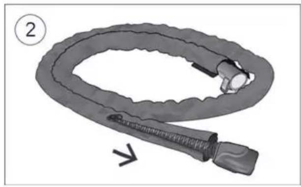
natural_image
Illustration of a coiled medical device with a bulbous tube and connector, labeled with number 2 (no text or symbols on the device itself)
natural_image
Illustration of a device's internal components with an arrow indicating a step, showing no text or symbols.
natural_image
Illustration of a portable air conditioner unit with a drop and lid, no text or symbols present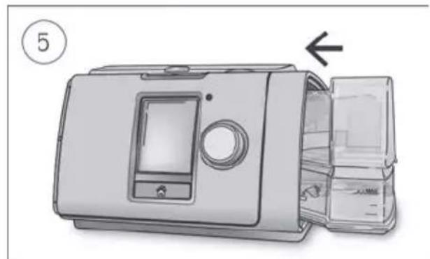
natural_image
Illustration of a device with an arrow pointing to the interior panel (no text or symbols present)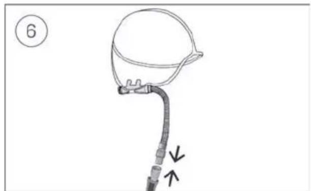
natural_image
Line drawing of a medical device with a bulb and tubing, no text or symbols present⚠ VORSICHT
natural_image
Illustration of a hand operating a device with a knob and directional arrow (no text or symbols)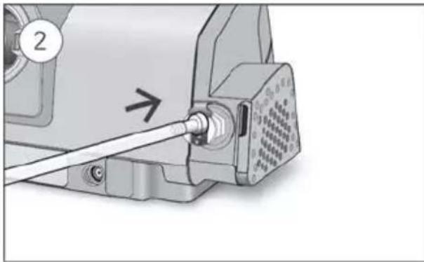
natural_image
Mechanical assembly diagram showing a sewing machine with a cable inserted, no text or symbols presentnatural_image
Illustration of a hand inserting a cable into a device component, showing mechanical parts and a directional arrow (no text or symbols)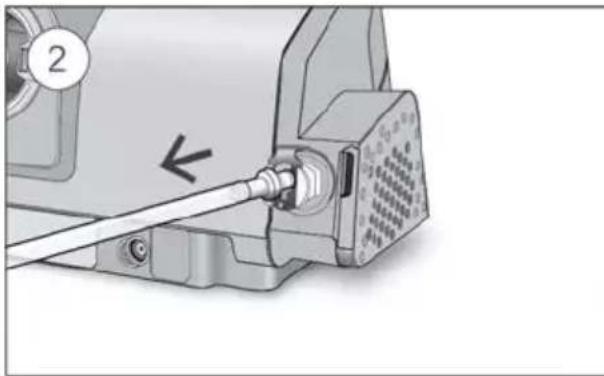
natural_image
Mechanical assembly diagram showing a sewing machine with a cable inserted, no text or symbols presentnatural_image
Line drawing of a person receiving medical attention from a cup (no text or symbols)natural_image
Illustration of a medical device with a digital display and control panel (no text or symbols visible)chemical
Simple line drawing of an oxygen gas cylinder with a valve and a cross symbol indicating rejection or cancellation.natural_image
Medical illustration showing a person receiving a medical procedure with a catheter and arrow (no text or symbols)natural_image
Illustration of a medical device with a digital display and control panel (no text or symbols visible)natural_image
Diagram of a device casing with internal compartments and a labeled arrow indicating direction (no text or symbols present)
natural_image
Technical line drawing of a mechanical component with a handle and internal structure (no text or symbols)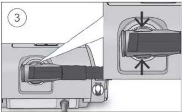
natural_image
Close-up of a mechanical connector with two arrows indicating assembly or connection (no text or symbols present)
natural_image
Two medical or industrial hoses shown: a curved device with connectors and a coiled tube with connectors (no text or symbols visible)natural_image
Close-up of a mechanical device component with a label '1' and a curved arrow indicating a motion or force (no readable text or symbols)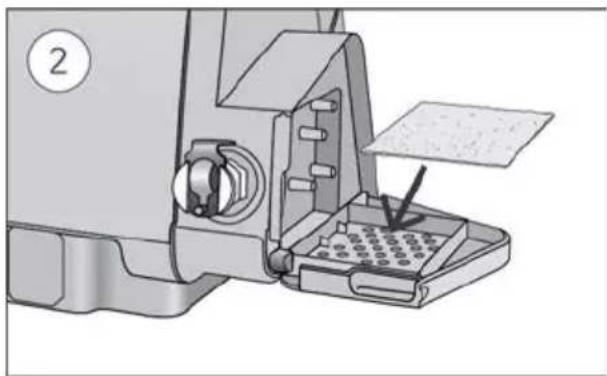
natural_image
Mechanical assembly diagram showing a sewing machine with a baseplate and paper holder (no text or symbols visible)natural_image
Illustration of a microwave oven with a gridded lid and ventilation slots, showing a curved arrow indicating motion (no text or symbols)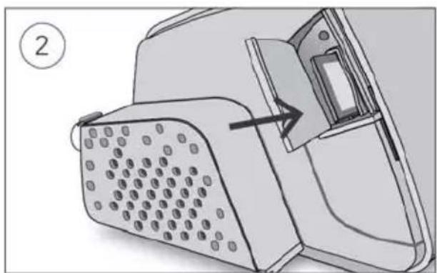
natural_image
Diagram of a device with a perforated base and a door, showing an arrow pointing to a component (no text or symbols present)natural_image
Mechanical component diagram showing a lever mechanism with directional arrows (no text or symbols)
natural_image
Technical line drawing of a mechanical component with no visible text or symbolsnatural_image
Illustration of a car body being lifted by an open hood, showing the component's assembly (no text or symbols)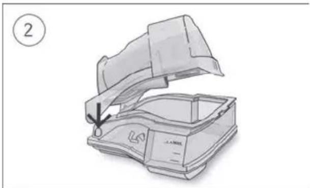
natural_image
Illustration of a device with an open lid and internal casing, showing a downward arrow indicating a process or operation (no text or symbols present)1 Sortie d'air
6 Écran
natural_image
Illustration of a device with attached cables and connectors, no text or symbols present
natural_image
Illustration of a coiled medical device with a bulb and connector, labeled with number 2 (no text or symbols on the device itself)
natural_image
Technical illustration of a device component with an arrow indicating a step, showing part details and assembly (no text or symbols present)
natural_image
Illustration of a portable air conditioner unit with a drop and lid, no text or symbols present
natural_image
Illustration of a device with an open lid and internal compartments, showing no text or symbols.
natural_image
Diagram of a medical device with a bulb and tubing, showing directional arrows (no text or symbols)ATTENTION
natural_image
Illustration of a hand operating a device with a knob and adjustment knob (no text or symbols)
natural_image
Mechanical assembly diagram showing a sewing machine with a cable inserted, no text or symbols presentnatural_image
Illustration of a hand using a cable to connect a connector into a device (no text or symbols visible)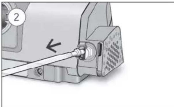
natural_image
Close-up of a sewing machine's cable being inserted into a socket (no text or symbols visible)natural_image
Illustration of a person receiving medical or surgical pressure with a catheter and arrow indicating direction (no text or symbols)natural_image
Illustration of a medical device with a digital display and control panel (no text or symbols visible)chemical
Simple line drawing of an oxygen gas cylinder with a valve and a cross symbol indicating rejection or cancellation.natural_image
Medical illustration showing a person receiving a catheter insertion, with no visible text or symbolsnatural_image
Illustration of a portable electronic device with a digital display and control panel (no text or symbols visible)natural_image
Diagram of a device casing with internal compartments and a labeled arrow indicating direction (no text or symbols present)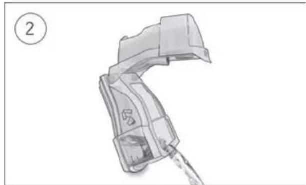
natural_image
Technical line drawing of a mechanical component with a handle and internal structure (no text or symbols)

natural_image
Close-up of a mechanical connector with two arrows indicating assembly or connection (no text or symbols present)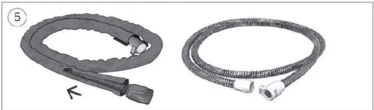
natural_image
Two medical or industrial hoses shown: a curved device with connectors and a coiled tube with connectors (no text or symbols visible)natural_image
Close-up of a mechanical device with a label pointing to a component, showing no visible text or symbols.
natural_image
Mechanical device with a paper feeding into a grid notebook, showing a brush and paper sheet (no text or symbols visible)natural_image
Diagram of a microwave oven with a gridded lid and ventilation slots, showing a curved arrow indicating motion (no text or symbols present)
natural_image
Diagram of a device with a perforated panel and a door, showing an arrow pointing to the interior (no text or symbols present)natural_image
Technical line drawing of a mechanical device with directional arrows indicating movement or force (no text or symbols)
natural_image
Technical line drawing of a mechanical component with no visible text or symbolsnatural_image
Diagram showing a mechanical component being lifted from a curved structure, with no visible text or symbols.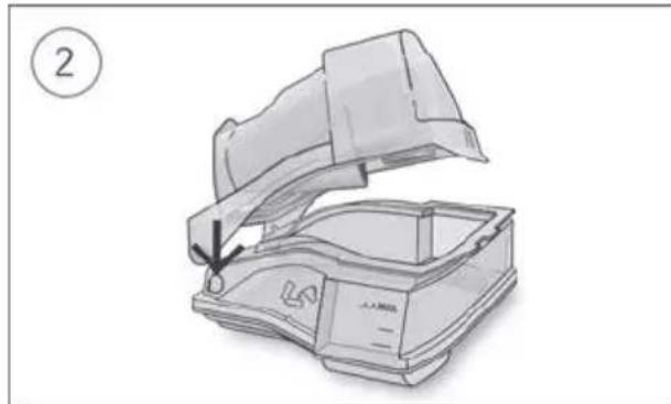
natural_image
Line drawing of a mechanical device with an open lid and internal structure, no text or symbols presentnatural_image
Diagram showing connections between a device and a battery with cables, no text or symbols present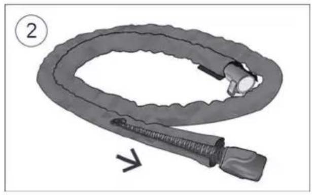
natural_image
Illustration of a coiled medical tube with a bulbous end, labeled with number 2 and an arrow indicating direction (no text or symbols on the diagram itself)
natural_image
Technical illustration of a device component with an arrow indicating a step, showing part details and assembly (no text or symbols present)
natural_image
Illustration of a portable air conditioner unit with a drop and lid, no text or symbols present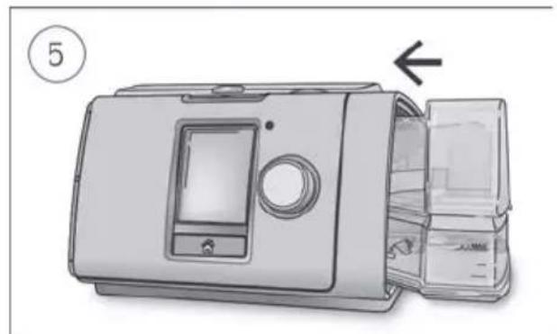
natural_image
Illustration of a device with an open lid and internal compartments, showing no text or symbols.
natural_image
Diagram of a medical device with a bulb and tubing, no text or symbols presentATTENZIONE
natural_image
Two-step diagram showing a hand operating a mechanical device with a cable inserted (no text or symbols present)natural_image
Medical illustration showing a hand holding a tube with an arrow pointing to the anatomical structure (no text or symbols present)natural_image
Illustration of a medical device with a digital display and control panel (no text or symbols visible)chemical
Simple line drawing of an oxygen gas cylinder with a valve and a cross symbol indicating rejection or cancellation.natural_image
Illustration of a person lying down with a medical tube inserted, no text or symbols presentnatural_image
Illustration of a portable electronic device with a digital display and control buttons (no text or symbols visible)natural_image
Diagram of a device casing with internal compartments and a labeled arrow indicating direction (no text or symbols present)
natural_image
Technical line drawing of a mechanical component with a handle and internal structure (no text or symbols)

natural_image
Close-up of a mechanical connector with two arrows indicating assembly or connection (no text or symbols present)
natural_image
Two medical or industrial hoses shown: a curved device with connectors and a coiled tube with connectors (no text or symbols visible)natural_image
Close-up of a mechanical device with a label pointing to a component (no readable text or symbols)
natural_image
Mechanical device with a paper feeding into a grid notebook, showing a brush and paper sheet (no text or symbols visible)natural_image
Diagram of a microwave oven with a gridded lid and ventilation slots, showing internal airflow direction (no text or symbols)
natural_image
Diagram of a device with a grid-patterned panel and an arrow pointing to a component (no text or symbols present)natural_image
Technical line drawing of a mechanical device with directional arrows indicating movement or force (no text or symbols)
natural_image
Technical line drawing of a mechanical component with no visible text or symbolsnatural_image
Diagram showing a mechanical component being lifted from a curved cover, with no visible text or symbols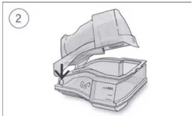
natural_image
Illustration of a portable radio with a canopy cover and a label showing number 2 (no text or symbols on the diagram itself)Equipment Directive, RED)

natural_image
Diagram showing connections between a device and a power adapter with earphones (no text or symbols present)
natural_image
Illustration of a coiled medical device with a bulb and connector, labeled with number 2 (no text or symbols on the device itself)
natural_image
Technical illustration of a device component with an arrow indicating a step, showing part details and assembly (no text or symbols present)
natural_image
Illustration of a portable air conditioner unit with a drop and lid, no text or symbols present
natural_image
Illustration of a microwave oven with a door panel and lid, showing internal compartments and a close-up view (no text or symbols)
natural_image
Diagram of a medical device with a bulb and tubing, showing directional arrows (no text or symbols)LET OP
natural_image
Two-step diagram showing a hand operating a mechanical device with a cable inserted (no text or symbols present)natural_image
Illustration of a person receiving medical treatment with a catheter (no text or symbols)natural_image
Illustration of a medical device with a digital display and arrow indicator (no text or symbols)- Druk op de Start/stop-knop om de therapie te starten.
chemical
Simple line drawing of an oxygen gas cylinder with a valve and a cross symbol indicating rejection or cancellation.natural_image
Medical illustration showing a patient with a surgical instrument inserted, no text or symbols presentnatural_image
Illustration of a portable electronic device with a digital display and control buttons (no text or symbols visible)natural_image
Illustration of a device with an open lid and internal compartments, showing a numbered step (1) and an arrow indicating direction (no text or symbols on the device itself)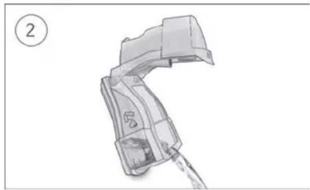
natural_image
Illustration of a handheld device with water flowing through its neck (no text or symbols)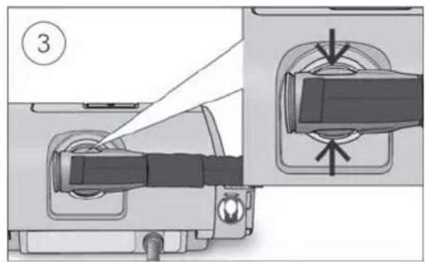

natural_image
Close-up of a welding torch connector with arrows indicating assembly or movement (no text or symbols)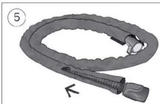
natural_image
Illustration of a coiled medical device with a bulb and connector, labeled with number 5 (no text or symbols on the device itself)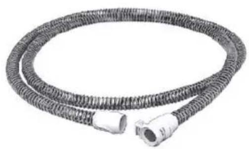
natural_image
Coiled black rubber hose with two connectors (no text or symbols visible)natural_image
Close-up of a mechanical device with a label pointing to a component, showing no visible text or symbols.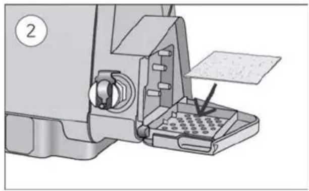
natural_image
Mechanical device with a paper feeding into a grid notebook, showing a brush and paper sheet (no text or symbols visible)natural_image
Diagram of a microwave oven with a gridded lid and ventilation slots, showing internal airflow direction (no text or symbols)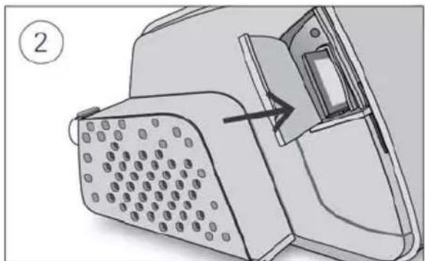
natural_image
Diagram of a device with a perforated panel and a close-up view showing internal components (no text or symbols)natural_image
Mechanical component diagram showing a lever mechanism with directional arrows (no text or symbols)
natural_image
Technical line drawing of a mechanical component with no visible text or symbolsnatural_image
Diagram showing a mechanical component being lifted from a curved structure, with no visible text or symbols.
natural_image
Line drawing of a portable electronic device with a lid open, showing internal components and a downward arrow indicating compression (no text or symbols)1 Salida de aire
6 Pantalla
natural_image
Diagram showing connections between a device and a battery with cables, no text or symbols present
natural_image
Illustration of a coiled medical device with a bulb and connector, labeled with number 2 (no text or symbols on the device itself)
natural_image
Technical illustration of a device component with an arrow indicating a step, showing part details and assembly (no text or symbols present)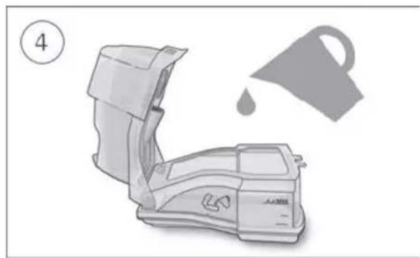
natural_image
Illustration of a portable air conditioner unit with a drop and lid, no text or symbols present
natural_image
Illustration of a device with an open lid and internal compartments, showing no text or symbols.
natural_image
Diagram of a medical device with a bulb and tubing, no text or symbols presentPRECAUCIÓN
natural_image
Two-step diagram showing a hand operating a mechanical device with a cable inserted, labeled 1 and 2 (no text or symbols present)natural_image
Illustration of a medical procedure with an arrow indicating direction (no text or symbols present)natural_image
Illustration of a medical device with a digital display and control panel (no text or symbols visible)chemical
Simple line drawing of an oxygen gas cylinder with a valve and a cross symbol indicating rejection or cancellation.natural_image
Line drawing of a person receiving medical or surgical pressure with a catheter, no text or symbols presentnatural_image
Illustration of a medical device with a digital display and control panel (no text or symbols visible)natural_image
Diagram of a device casing with internal compartments and a labeled arrow indicating direction (no text or symbols present)
natural_image
Technical line drawing of a mechanical component with a handle and internal structure (no text or symbols)

natural_image
Close-up of a mechanical connector with two arrows indicating assembly or connection (no text or symbols present)
natural_image
Two medical or industrial hoses shown: a curved device with connectors and a coiled tube with connectors (no text or symbols visible)natural_image
Close-up of a mechanical device with a clamped connector and a numbered label (1), no visible text or symbols.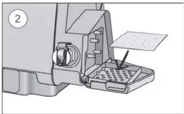
natural_image
Mechanical device with a paper feeding into a grid array (no visible text or symbols)natural_image
Diagram of a microwave oven with a gridded lid and ventilation slots, showing internal components and airflow direction (no text or symbols)
natural_image
Diagram of a device with a perforated panel and a door, showing an arrow pointing to a component (no text or symbols present)natural_image
Mechanical component diagram showing a lever mechanism with directional arrows (no text or symbols)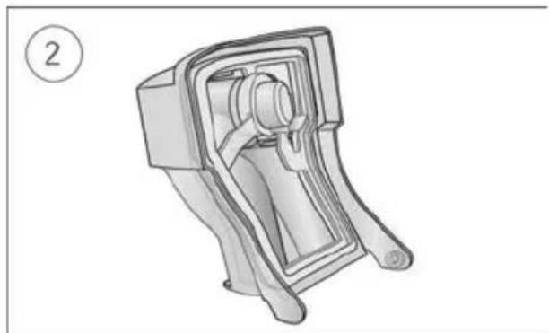
natural_image
Technical line drawing of a mechanical device with no visible text or symbolsnatural_image
Diagram showing a mechanical component being lifted from a housing, with no visible text or symbols
natural_image
Illustration of a portable radio device with a lid open, showing internal components and a downward arrow indicating compression (no text or symbols)1 Saída de ar
6 Ecrã
2 Tampa do filtro de ar 7 Tampa do adaptador
natural_image
Diagram showing connections between a device and a power adapter with cables (no text or symbols)
natural_image
Illustration of a coiled medical device with a bulb and connector, labeled with number 2 (no text or symbols on the device itself)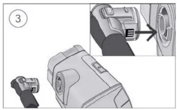
natural_image
Technical illustration of a device component with an arrow indicating a step, showing part details and assembly (no text or symbols present)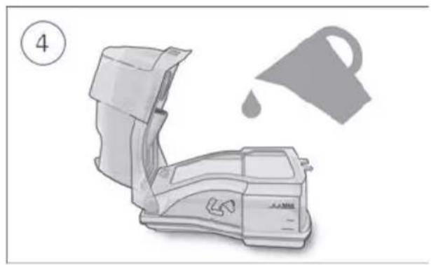
natural_image
Illustration of a portable air conditioner unit with a drop and lid, no text or symbols present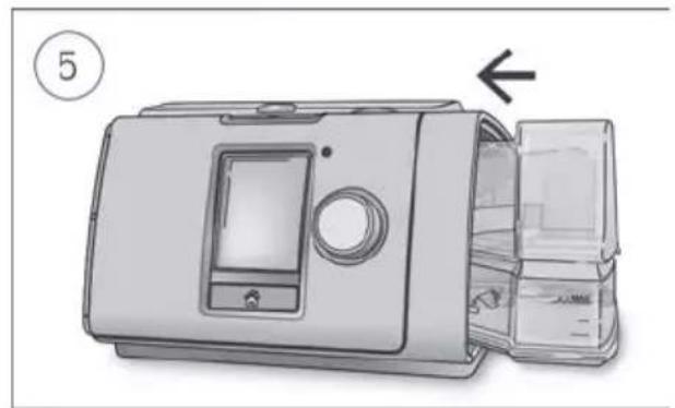
natural_image
Illustration of a microwave oven with a door panel and lid, showing internal compartments and a close-up view (no text or symbols)
natural_image
Diagram of a medical device with a bulb and tubing, showing directional arrows (no text or symbols)PRECAUÇÃO
natural_image
Illustration of a hand pressing a button on a device with a knob, showing a downward arrow (no text or symbols present)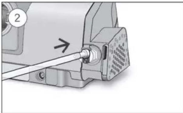
natural_image
Mechanical assembly diagram showing a pipe inserted into a motor housing (no text or symbols visible)Para remover oxigénio suplementar:
natural_image
Illustration of a hand using a cable to adjust or install an electronic component (no text or symbols visible)
natural_image
Close-up of a sewing machine's cable being inserted into a socket (no text or symbols visible)natural_image
Illustration of a person receiving medical or surgical pressure with a catheter, no text or symbols presentnatural_image
Illustration of a printer with a digital display and control panel (no text or symbols visible)chemical
Simple line drawing of an oxygen gas cylinder with a valve and a cross symbol indicating rejection or cancellation.natural_image
Illustration of a person receiving medical or surgical pressure from a tube, with an arrow indicating direction (no text or symbols present)- Remova a sua cânula nasal de alto fluxo.
natural_image
Illustration of a medical device with a digital display and control panel (no text or symbols visible)Para regular a taxa de Fluxo:
natural_image
Diagram of a device with an open lid and internal compartments, showing a numbered step (1) and an arrow indicating direction (no text or symbols on the diagram itself)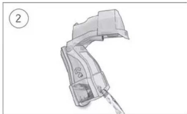
natural_image
Illustration of a mechanical device with a handle and internal components, labeled with number 2 (no text or symbols on the device itself)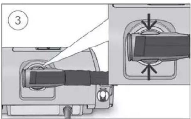
natural_image
Close-up of a mechanical connector with arrows indicating assembly or connection (no text or symbols)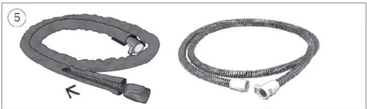
natural_image
Two medical or industrial hoses shown: a coiled tube with connectors and a coiled tube with two connectors (no text or symbols visible)natural_image
Close-up of a mechanical device with a label pointing to a component (no readable text or symbols)
natural_image
Mechanical device with a paper feeding into a grid notebook, showing a brush and paper sheet (no text or symbols visible)natural_image
Illustration of a microwave oven with a gridded lid and ventilation slots, showing a curved arrow indicating motion (no text or symbols)
natural_image
Diagram of a device with a grid-patterned panel and an arrow pointing to a component (no text or symbols present)natural_image
Mechanical component diagram showing a lever mechanism with directional arrows (no text or symbols)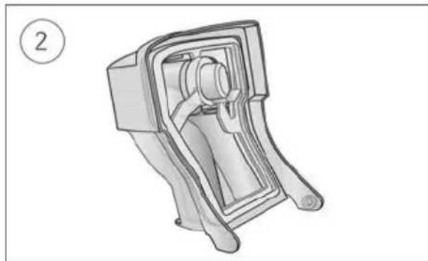
natural_image
Technical line drawing of a mechanical component with no visible text or symbolsnatural_image
Diagram showing a mechanical component being lifted from a housing, with no visible text or symbols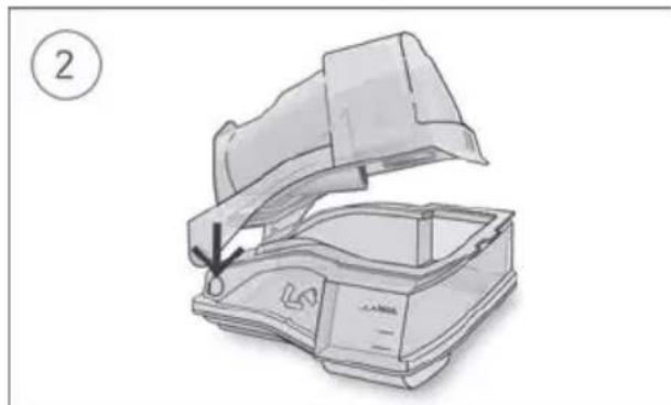
natural_image
Illustration of a portable electronic device with an open lid and internal casing, showing a handle and base (no text or symbols)Bella Vista NSW 2153 Australia
See ResMed.com for other ResMed locations worldwide. Air10, Lumis, ClimateLine, SlimLine, HumidAir, SmartStart and VPAP are trademarks and/or registered trademarks of the ResMed family of companies. For patent and other intellectual property information, see ResMed.com/ip. SD Logo is a trademark of SD-3C, LLC. © 2021 ResMed. 288429/2 2021-06