
Ultimatte 12 - Audiovisual Equipment Blackmagic Design - Free user manual and instructions
Find the device manual for free Ultimatte 12 Blackmagic Design in PDF.
User questions about Ultimatte 12 Blackmagic Design
0 question about this device. Answer the ones you know or ask your own.
Ask a new question about this device
Download the instructions for your Audiovisual Equipment in PDF format for free! Find your manual Ultimatte 12 - Blackmagic Design and take your electronic device back in hand. On this page are published all the documents necessary for the use of your device. Ultimatte 12 by Blackmagic Design.
USER MANUAL Ultimatte 12 Blackmagic Design
To go directly to your preferred language, simply click on the hyperlinks listed in the contents below.
English 3
日本語 104
Français 206
Deutsch.308
Espanol 410
中文 512
614
Pycckn.716
Italiano 818
Portugues 920
Türkce 1022

Welcome
Thank you for purchasing Blackmagic Ultimatte.
Ultimatte has been the premiere keyer used in the film and television industries for decades and no other keyer comes close to the performance that Ultimatte can achieve. It's powerful enough to handle fine detail on key edges as well as retaining stronger colors, even when those foreground colors are close to the key color. Even uneven green and blue screen backdrops can be handled.
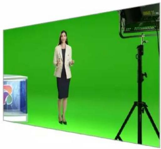
However, what makes Ultimatte so powerful is its ability to map shadows onto the new background layer combined with its color spill management that lets you create extremely realistic environments. In many ways, Ultimatte is much more than a keyer as it's really a real time advanced compositor for creating photorealistic virtual environments. Ultimatte lets you move your talent to any location at the click of a button and the results look real.
This instruction manual contains all the information you need to get started with Ultimatte as well as detailed instructions on how to operate Ultimatte using Blackmagic Ultimatte Software Control from your computer or Smart Remote 4.
Also, please check the support page on our website at www.blackmagicdesign.com for the latest version of this manual and for updates to your Blackmagic Ultimatte's software. Keeping your software up to date will ensure you get all the latest features! We are continually working on new features and improvements, so we would love to hear from you!

Grant Petty
CEO Blackmagic Design
Contents
Introducing Ultimatte 6 Status Bar 29
What is a Matte? 6 Monitor Out 30
Types of Mattes 7 Setting Controls 30
Getting Started 10 Using the Media Pool 31
Plugging in Power 10 Supported File Formats for Stills 32
Setting the Language 10 Stills Background and Layer Options 32
Connecting your Camera Foreground 11 Ultimatte Compositing Workflow 33
Connecting to a Switcher 12 Quick Guide to Building a Composite 34
Monitoring Setting the Foreground Backing Color 34
Setting the Auto Composite 12 Setting Screen Correction 35
Monitor Cascade 13 Setting the Matte Density 36
Connectors Perfecting your Composite 36
Supported Video Formats 16 Advanced Ultimatte Controls 38
Using the Front Control Panel 17 Adjusting Matte Controls 38
LCD Display 17 Adjusting Foreground Flare Controls 43
Quick Preset Buttons 18 Adjusting Foreground Ambiance Controls 45
Menu 18 Adjusting Brightness, Color.
Lock 18 Contrast and Saturation 46
LCD Menu Settings 18 Additional Background Settings 48
Setup Settings 19 Additional Layer Settings 48
Network Settings 20 Matte Input Settings 50
Matte Status 21 Settings 53
Input Status 22 System 53
Reset 22 Media 53
Controlling Ultimatte 23 Inputs 53
Ultimatte Software Control 23 Outputs 54
Installling Ultimatte Software 23 Monitor Cascade 56
Connecting your Computer 24 On Air Settings 56
Assigning a Unit Number 25 GPI and Tally Settings 57
Selecting the Ultimatte Main Unit 27 Monitor Out Settings 59
Ultimatte Software Control Layout 28 Presets 61
Main Menu Buttons 28 Saving and Managing Presets 61
Information, File Control and Auto Key 28 Assigning presets 62
Groups 29 Importing and Exporting Presets 63
Functions 29 Archives 64
Creating an Archive 64
Restoring an Archive 65
Customizing the Menus 66
Camera Control via Ultimatte 12 HD Mini 67
Connecting to a Network 69
Setting the IP Address 69
Setting the IP Address for your Smart Remote 4 70
Assigning Unit Numbers 70
Blackmagic Ultimatte Setup 72
Updating the Internal Software 73
Using Smart Remote 4 74
Connecting Power 74
Connecting to Ultimatte 74
Turning on Smart Remote 4 75
Updating your Smart Remote 4 75
Uninstalling Software 75
Installing Ultimatte Smart Remote Setup 78
Connecting a USB Keyboard and Mouse 79
Rack Installation 80
Installing Front Rack Ears 81
Installing Rear Rack Ears 81
Installing Chassis Bumpers 81
Rack Mounting 82
Developer Information 84
Controlling Ultimatte using Telnet 84
Blackmagic Ultimatte 12 Ethernet Protocol 85
Help 101
Regulatory Notices and
Safety Information 102
Warranty 103
Introducing Ultimatte
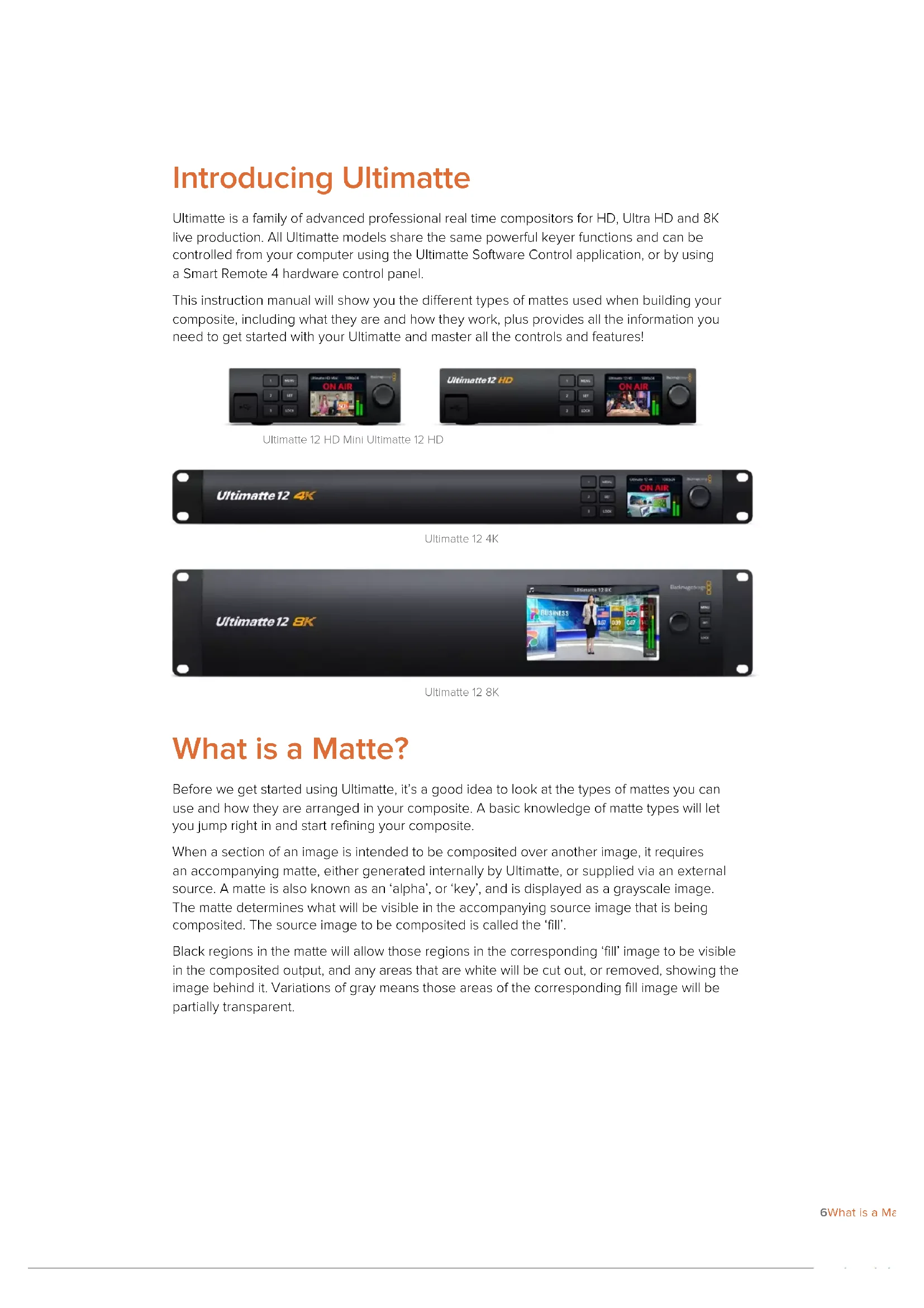
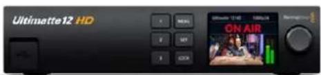
Ultimatte is a family of advanced professional real time compositors for HD, Ultra HD and 8K live production. All Ultimatte models share the same powerful keyer functions and can be controlled from your computer using the Ultimatte Software Control application, or by using a Smart Remote 4 hardware control panel.
This instruction manual will show you the different types of mattes used when building your composite, including what they are and how they work, plus provides all the information you need to get started with your Ultimatte and master all the controls and features!
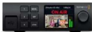
Ultimatte 12 HD Mini Ultimatte 12 HD

Ultimatte 12 4K
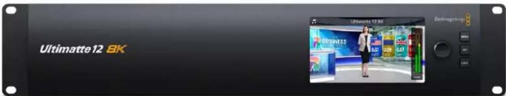
Ultimate 128K
What is a Matte?
Before we get started using Ultimatte, it's a good idea to look at the types of mattes you can use and how they are arranged in your composite. A basic knowledge of matte types will let you jump right in and start refining your composite.
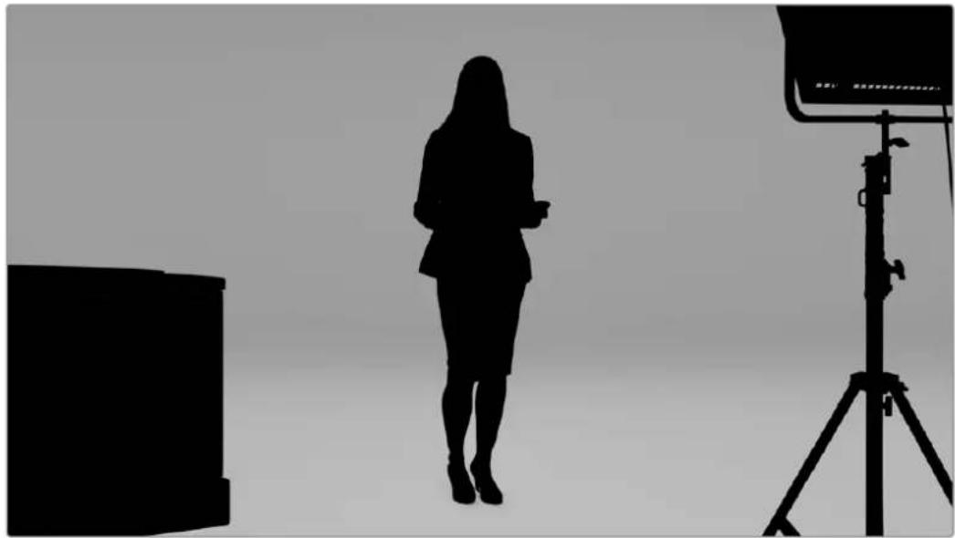
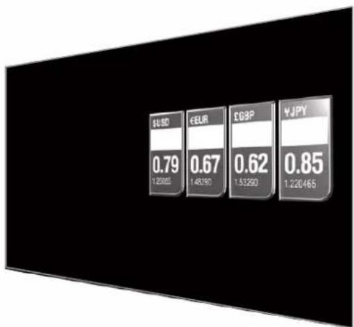
When a section of an image is intended to be composited over another image, it requires an accompanying matte, either generated internally by Ultimatte, or supplied via an external source. A matte is also known as an 'alpha', or 'key', and is displayed as a grayscale image. The matte determines what will be visible in the accompanying source image that is being composited. The source image to be composited is called the 'fill'.
Black regions in the matte will allow those regions in the corresponding 'fill' image to be visible in the composited output, and any areas that are white will be cut out, or removed, showing the image behind it. Variations of gray means those areas of the corresponding fill image will be partially transparent.

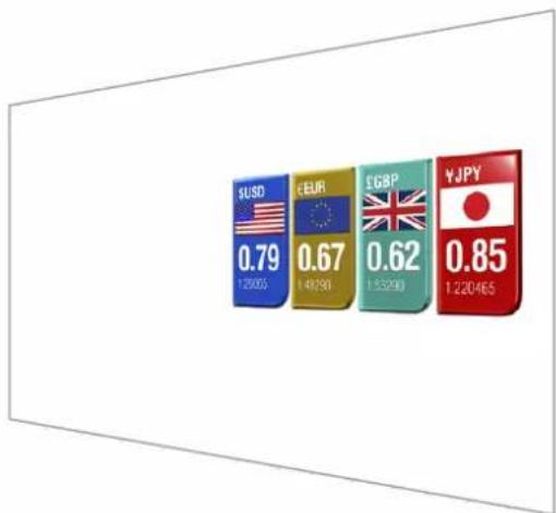
An example of a final output comprised of background, foreground and layers composited together
Types of Mattes
Different matte types are used for specific purposes to separate areas of the corresponding image into foreground and background elements, or to include or exclude sections of the matte you want to keep or discard.
Below is a description of the types of mattes used.
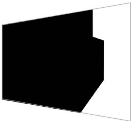
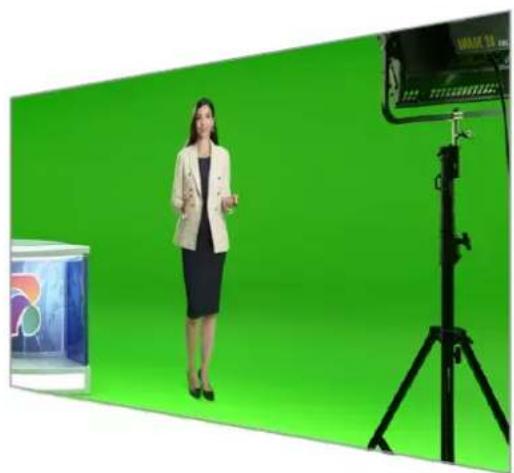
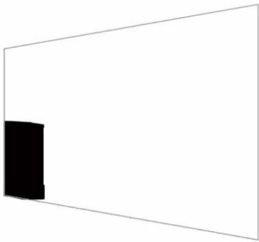
Background Matte
The background matte lets you extract a section from the background and place it over the foreground.

For example, you may have a virtual set as your background image that has a partition on one side. Using a background matte that precisely matches the partition in your virtual set, you can extract the partition from the background and the talent can walk behind it. This is an excellent way to create a foreground element using the background image and keeps the layer input free for additional foreground items. It's important to note that elements to be extracted from the background must be completely opaque.
Matte
This is the primary matte you will be working within your composite. This matte is derived using the source connected to the foreground input. Typically a presenter in front of a green screen. The matte is generated internally by analyzing the backing color in the source video and will determine what is visible in the foreground image.
TIP Objects that obscure the backing color, either partly or completely, will be visible in the composited image. In the matte, fully opaque black means the corresponding areas in the fill image will be completely visible. Shades of gray means partially transparent.
Garbage Matte
A garbage matte excludes areas of a source you don't want to include in your composite.
For example, there may be lights and gripping equipment visible around the edges of your foreground image. If you want to mask out these unwanted areas, a garbage matte lets you do that. Garbage mats can be generated externally so they precisely match shapes in your source video, and connected to the garbage matte input.
TIP You can create an internal mask using the 'window' controls on your Ultimatte. This can be a great tool for creating a rough, fast garbage matte. For more information on how to set up window masks, refer to the 'matte input/window' section.
Holdout Matte
This matte is similar to a garbage matte, however, it lets you mask out areas from within the visible foreground so they are ignored by the matte.
For example, imagine a portion of a virtual set needs to appear green in the foreground. This will present a challenge because anything green will key out and reveal the background underneath. A holdout matte can be created to exclude that particular area within the set, which will prevent it from being keyed.
Layer Matte
The layer matte lets you add more foreground elements to the scene. For example, if you want to add graphics over the top of the composite.
The layer matte can include transparency elements and you can swap the layer positioning in the final composite. For example, you may want to change the layer order during your production so the layer input appears in front of, then behind, the talent. You can even set a transition rate so the order change is a smooth mix transition.
For more information, refer to the 'Matte input settings/setting the layer order' section.
Getting Started
Getting started with your Ultimatte is as simple as plugging in power, plugging in your camera foreground, connecting your background source and then plugging the automatically generated composite into a switcher. This getting started section will show you the basics of setting up a fast auto composite for your live production. The model used in this section is an Ultimatte 12 HD Mini which has HDMI connectors, but all SDI Ultimatte models share similar features and the setup is exactly the same for their SDI connectors.
Plugging in Power
To power your Ultimatte, plug a standard IEC cable into your Ultimatte's power input on the rear panel.
Setting the Language
Once powered, the LCD display will prompt you to select your language. Using the settings dial, scroll to the language you wish to use and press the flashing 'set' button to confirm your selection.
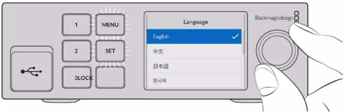
1 Use the settings dial to select your language
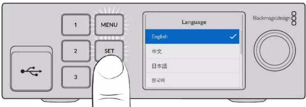
2 Press the 'set' button to confirm your setting.
Connecting your Camera Foreground
With power connected, you can now plug your camera into the camera foreground input.
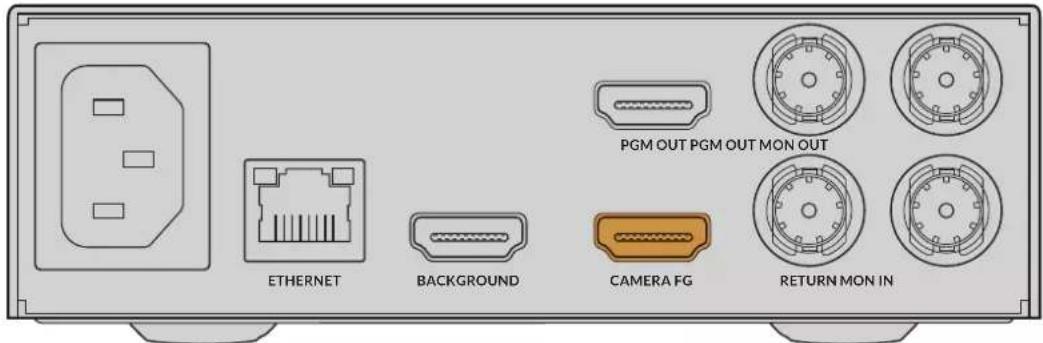
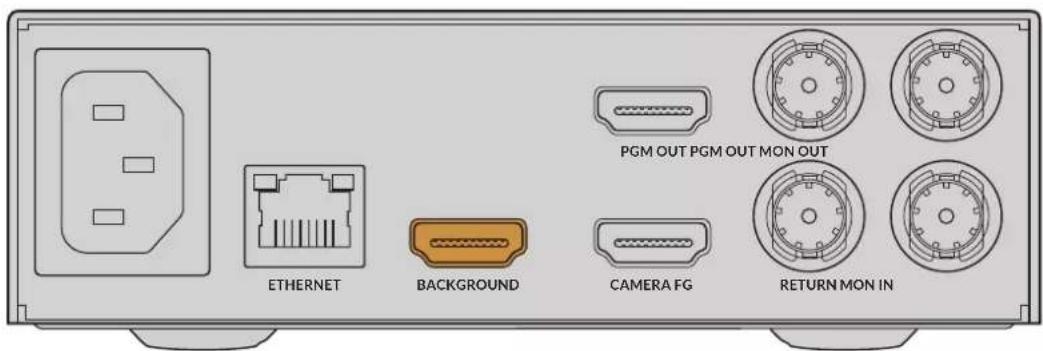
Connecting the Background
Now plug your background source into the 'background' input. For example, this could be a video feed from a gaming console, or a virtual set from a HyperDeck video feed, or even a still graphic you can load into the media pool using Ultimatte Software Control. For more information, refer to the 'using the media pool' section.
Generating an Auto Composite
As you plug in your sources, Ultimatte will automatically build your composite and you can see it happening on the front panel's LCD. Once all sources are connected, the automatically generated composite is ready for output.
NOTE The foreground input will determine the video format for all inputs. For example, if you have 1080 HD connected to the foreground input, make sure all the other sources are set to 1080 HD.
Connecting to a Switcher
The program video output lets you connect the final composite to an ATEM switcher, for example an ATEM Mini or ATEM SDI. If your foreground input source has embedded audio and timecode, they will be included in the program output.
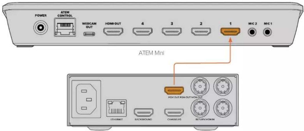
Ultimatte 12 HD Mini
Connect your Ultimatte's program output to an ATEM switcher
Monitoring
Plugging a monitor into the monitor output lets you view the background source, camera foreground and internally generated matts. This is helpful when refining your composite. For more information refer to the 'monitor out' section.
The monitor input and output is also used for cascade monitoring. This feature lets you daisy chain multiple Ultimatte units via SDI so you can monitor the sources and outputs on all units via one single Ultimatte, rather than connecting monitors to each unit individually. For more information, refer to the 'monitor cascade feature' section.
Setting the Auto Composite
The automatically generated composite is ready to be used as soon as your foreground and background sources are connected. You can reset the starting composite at any time by using the 'auto key' function in the front panel's LCD menu. We recommend resetting the auto key each time the lighting changes or you shift the camera's position.
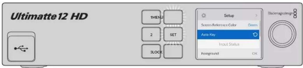
Use the auto key function to reset your composite
Your Ultimatte will set an automatic composite with green selected as the backing color by default. If your lighting is optimized and your green screen environment has been carefully set up, the automatic composite generated by Ultimatte can be all you need to do.
If you are setting up a highly detailed and complex virtual set, or your green screen requires some help from Ultimatte, you can use Ultimatte Software Control on your computer or a Smart Remote 4 hardware panel to make precise adjustments to the various matte controls and hand craft your final composite. This includes features such as screen correction which can help improve your composite if your green screen has uneven lighting or blemishes that are visible in your auto key.
We believe you will enjoy exploring your Ultimatte and developing your own workflow to produce amazing virtual environments. You can even build larger setups using multiple cameras and an Ultimatte unit on each camera so you can have different camera angles on your virtual set. When constructing graphics and backgrounds that are tailored to each angle, the possibilities are truly endless!
Please keep reading this manual for information on how to use your Ultimatte's front panel to change settings, plus how to control the unit using Ultimatte Software Control.
Monitor Cascade
The monitor cascade feature lets you view the monitor output from up to eight Ultimatte units via one single unit.
To connect up to eight Ultimatte units together and use the monitor cascade feature, each unit needs to be connected to common analog reference or to foreground sources that are locked together. The Ultimatte units can then be daisy chained via their monitor inputs and outputs, with the last unit plugged into a monitor. Then when you select any of the eight units in Ultimatte Software Control, the monitor output for that particular unit can be viewed from the monitor output on the last unit.
To enable the monitor cascade feature in Ultimatte Software Control, click on the 'info' icon in the files and information section, and check the 'monitor cascade' checkbox in the 'configuration' tab.
Switching the monitor cascade feature on or off will affect the SDI monitor output but does not affect your Ultimatte's front panel LCD. The LCD on the front panel always displays the program output for that unit.
Below is an example showing how two Ultimatte units are daisy chained for cascade monitoring.
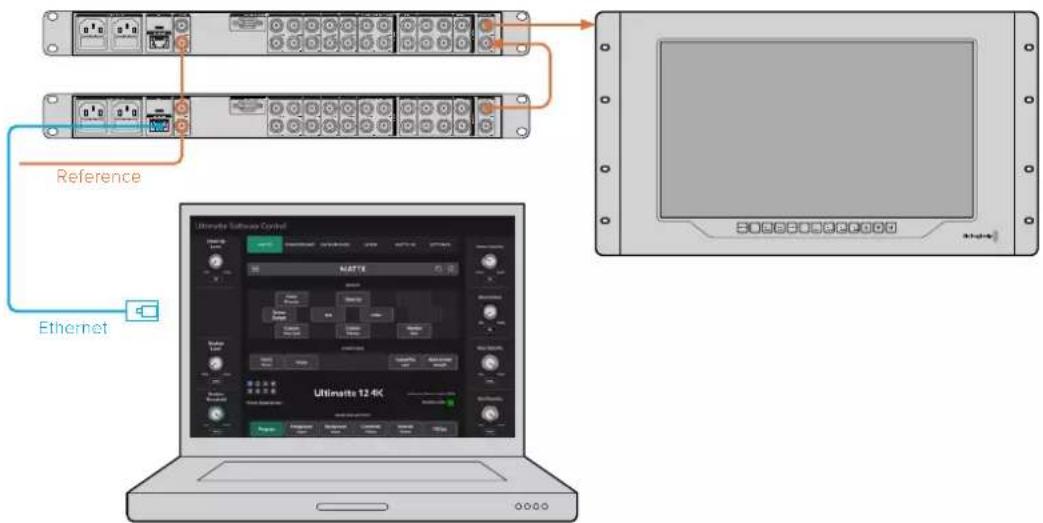
For more information on cascade monitoring, refer to the 'settings/monitor cascade' section.
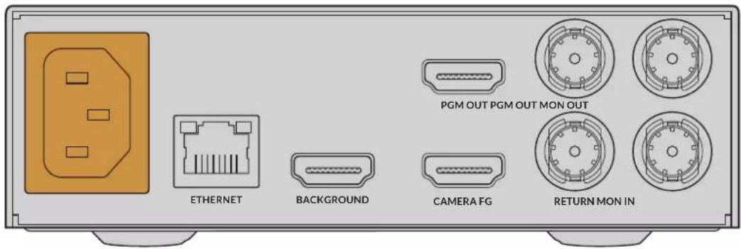
Connectors
Use the connectors on your Ultimatte's rear panel to connect power, video inputs, video outputs and to connect your Ultimatte to a computer or network. On smaller units that have fewer inputs you can load stills into the media pool and assign them to specific sources instead of plugging in those sources via a connector. Refer to the 'Using the Media Pool' section for more information.
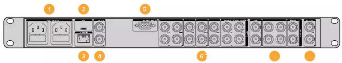
Ultimate 12 4K
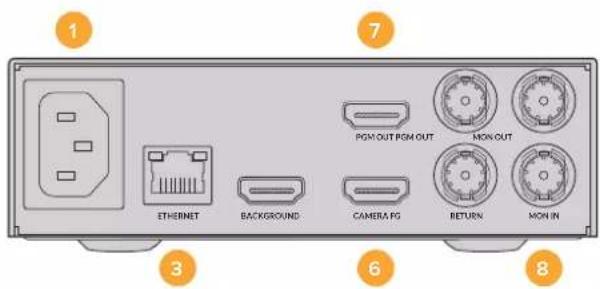
Ultimate 12 HD Mini
1 Power
Power your Ultimatte by connecting a standard IEC cable to the rear panel. If your Ultimatte model has an additional IEC power input, you can connect to another power source for redundancy. For example, connecting the second input to an uninterrupted power supply, or UPS, will instantly take over if the primary source fails.
2 USB
On larger Ultimatte units, use the USB port on the rear panel to connect your Ultimatte to your computer. This allows you to update and configure your Ultimatte with Blackmagic Ultimatte Setup. On smaller Ultimatte models the USB port is on the front panel.
3 Ethernet
The Ethernet port lets you connect to a computer, network or Smart Remote 4 so you can control your Ultimatte using Ultimatte Software Control. For more information, refer to the 'connecting your computer' and 'connecting to a network' sections later in this manual.
4 Reference
Most Ultimatte models feature reference input and output connectors. You can connect a reference signal to the reference input and sync your Ultimatte to an external master sync source. The reference out lets you loop the reference input to another Ultimatte or video equipment.
5 GPIO
On larger Ultimatte models, this connector is for use with an external GPI interface. GPI inputs and outputs let you trigger Ultimatte preset files as GPI events. For more information refer to the 'GPI and tally settings' section.
6 Video Inputs
Each source input used in a composite should be carefully planned, so the elements that build your shot can be arranged into specific layers. Each source should be the same video format and connected to its determined source input so you always know where everything is, and you can manage your composite more effectively.
All inputs and outputs support SD and HD. Ultimatte 12 and Ultimatte 12 4K support Ultra HD. Ultimatte 12 8K has additional support for 8K formats.
Background Input
The background input is the image you want to use as the background for your composite. Depending on the Ultimatte model you are using, plug the background input into the BG IN or Background connector. You can also select a still from the media pool to use as a background.
Background Matte Input
If you want to extract a section of the background to use as a foreground element, choose a still from the media store or plug the background matte source into the BG MATTE IN connector.
Garbage Matte Input
A garbage matte allows you to exclude areas of a source so they are not included in your composite, for example lights or gripping equipment visible around the edges of your foreground image. To add a garbage matte plug a source containing an externally generated garbage matte into the G MATTE IN connector. You can also select a still from the media pool to use as a garbage matte.
Camera Foreground Input
Plug the foreground image you want to composite over the top of the background into the FG IN or Camera FG connector. The foreground image is typically the talent in front of a green screen.
Holdout Matte Input
A holdout matte lets you define an area of the foreground that you do not want to be keyed out, for example a green logo on the front of a desk. To add a holdout matte select a still from the media pool or plug a source containing an externally generated holdout matte into the H MATTE IN connector.
Layer Input
The layer input is for any additional video or graphics you want to add to your composite. You can also select a still from the media pool to use as a layer.
Layer Matte Input
Similar to other matte inputs, this input lets you connect an externally generated matte so you can precisely add the layer input source into your composite. You can also select a still from the media pool to use as a layer matte.
Return
The 'return' connector on the rear panel of Ultimatte 12 HD Mini is for connecting camera control and tally data from an SDI ATEM switcher. For more information, refer to the 'Camera Control via Ultimatte 12 HD Mini' section for more information.
Monitor Input
The monitor input is important for daisy chaining to other Ultimatte units when using the powerful monitor cascade feature. Refer to the 'settings' section for more information.
7 Video Outputs
Source Loop Outputs
On some Ultimatte models, each source input has its own dedicated loop SDI output.
Program Outputs 1 and 2
Plug a program output, marked PGM into a switcher, for example an ATEM Mini or ATEM SDI.
Ultimatte 12 HD Mini models have both an SDI and HDMI program output.
Fill Outputs 1 and 2
If the Ultimatte unit you are using features fill outputs, then you can connect these outputs into a recording deck, and into a switcher for final compositing.
Matte Outputs 1 and 2
If the Ultimatte model you are using has matte outputs, then you can plug these into a recording deck, and into a switcher for final compositing. The matte output includes the internal matte, plus the garbage matte and holdout matte if enabled.
Talent Out 1 and 2
The talent output on larger Ultimatte models lets your talent monitor the final composite so they can position themselves in the frame and coordinate their actions to the composited image.
The talent output has a 'mirror' setting that lets you flip the talent output horizontally. Using this feature, the talent can see his or her position on the screen without needing to compensate for reversed camera left and right staging. Refer to the 'settings/talent mirror' section for more information.
8 Monitor Output
Plug the monitor output into a monitor or recording deck, the monitor output can be used to view any of the inputs, outputs or internal matte signals. This connector is also used for daisy chaining to other Ultimatte units when using the powerful monitor cascade feature. Refer to the 'settings' section for more information.
Supported Video Formats
All inputs and outputs support SD and HD. Ultimatte 12 and Ultimatte 12 4K support Ultra HD. Ultimatte 12 8K has additional support for 8K formats.
| Connection Types Formats | |
| SD SDI or HD-SDI 625i50 PAL | 525i59.94 NTSC, 720p50, 720p59.94, 720p60, 1080PsF23.98, 1080PsF24, 1080PsF25, 1080PsF29.97, 1080PsF30, 1080i50, 1080i59.94, 1080i60, 1080p23.98, 1080p24, 1080p25, 1080p29.97, 1080p30, 1080p50, 1080p59.94, 1080p60 |
| HDMI 625i50 PAL, 525i59.94 | NTSC, 720p50, 720p59.94, 720p60, 1080i50, 1080i59.94, 1080i60, 1080p23.98, 1080p24, 1080p25, 1080p29.97, 1080p30, 1080p50, 1080p58.94, 1080p60 |
| Level A or level B 3G-SDI 1080p50 | 50, 1080p59.94, 1080p60 |
| 6G-SDI or 12G-SDI 2160p23.98 | 2160p24, 2160p25, 2160p29.97, 2160p30, 2160p50, 2160p59.94, 2160p60 |
| Quad link 2SI 6G-SDI or Dual link 2SI 12G-SDI | 4320p23.98, 4320p24, 4320p25, 4320p29.97, 4320p30 |
| Quad link 2SI 12G-SDI 4320p50 | 4320p59.94, 4320p60 |
Using the Front Control Panel
On the control panel's LCD you can view the program output plus monitor useful information such as audio levels, the video format and frame rate, and the name of your Ultimatte unit. When you press the menu button the settings menu will appear where you can change settings and check the connection status on all inputs. The three numbered buttons let you instantly recall presets.
This section provides a brief overview of the features included on the front panel.
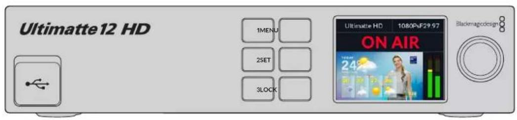
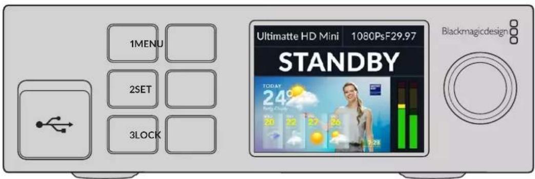
LCD Display
Depending on the Ultimatte 12 model you are using, the LCD displays the program output and the following information.

NOTE Ultimatte 12 HD Mini receives on air tally status from an ATEM switcher connected via the HDMI PGM or SDI Return connectors. Refer to the 'Camera Control via Ultimatte 12 HD Mini' for more information.
Larger Ultimatte models detect tally via the GPIO connector on the rear panel when connected to a third party GPI interface. For more information, refer to the 'GPI and Tally Settings' section.
USB
If your Ultimatte has a USB connector on the front panel, you can use this port to connect the unit to your computer. This USB-C port is used for updating and configuring the unit with Blackmagic Ultimatte Setup. On larger Ultimatte models the USB-C port is on the rear panel.
Quick Preset Buttons
The three numbered buttons on the front panel are used to recall quick presets. If a quick preset is available the corresponding button is illuminated green, when a quick preset is active the button will be blue.
For more information, refer to the 'presets' section later in this manual.
Menu
Press the 'menu' button to open and close the settings menu.
Lock
Press and hold the 'lock' button for 1 second to lock the front panel. This disables the buttons, preventing anyone from accidentally changing any settings. The button will illuminate red when active.
Press and hold for 2 seconds to unlock the panel.
LCD Menu Settings
All the settings for your Ultimatte are located under the main 'setup' page. Simply scroll through the setup menu to find the settings you need to change. These include network and matte settings, checking the status of connected inputs, appearance settings and resetting the unit to factory settings.
Press the 'menu' button on the front panel to open the menu settings.
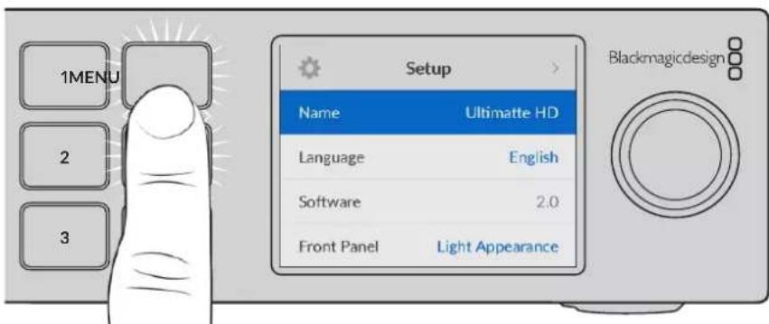
Rotate the settings dial to scroll through the menu.
With a menu item selected, press the 'set' button.
Adjust settings using the settings dial and confirm them by pressing the 'set' button. Press 'menu' to return to the home screen.
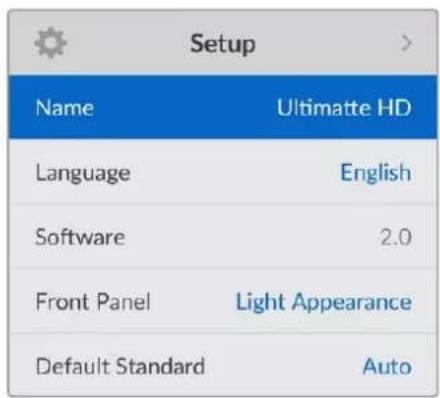
Setup Settings
The setup settings allow you to change your Ultimatte's language selection, select the default video standard and change the appearance of the LCD display.
Name
When more than one Ultimatte is on the network, you may wish to give them discrete names. This can be set using Blackmagic Ultimatte Setup.
Language
Blackmagic Ultimatte supports 13 languages, including English, Chinese, Japanese, Korean, Spanish, German, French, Russian, Italian, Portuguese, Turkish, Ukrainian and Polish.
To select the language:
1 Scroll the search dial down to select language and press set.
2 Use the settings dial to select the language and press set. Once selected you will automatically return to the setup menu.
Software
Displays the current software version for your Blackmagic Ultimatte.
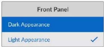
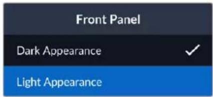
Front Panel
Set your Ultimatte's front panel to 'light' mode for a brightly illuminated LCD. Use 'dark' mode for dimly lit environments where a bright LCD may be distracting, for example when mounted in a rack in a production facility.
Default Standard
When set to 'auto' the camera or source connected to your Ultimatte's foreground input will determine the video format for all other inputs and all outputs.
You can choose another video format from the default standard menu. This can be useful when you first turn on your Ultimatte without a foreground input, so all the outputs will be set to that default video standard.
Network Settings
The network settings allow you to change your Ultimatte's IP address, subnet mask and gateway settings. You can also switch between network protocols.
| Network | |
| Protocol | Static IP |
| IP Address | 192.168.24.100 |
| Subnet Mask | 255.255.255.0 |
| Gateway | 192.168.24.1 |
Protocol
Your Ultimatte unit is shipped with a default IP address of 192.168.10.220 but you can change this address if you want to connect to a network. This is also important when sharing multiple Ultimatte units on your network and controlling them using Ultimatte Software Control.
IP Address, Subnet Mask and Gateway
Once Static IP is selected, you can enter your network details manually.
To change the IP address:
1 Use the settings dial to highlight 'IP address' and press the flashing 'set' button on your Ultimatte's front panel.
2 Rotate the settings dial to adjust your IP address, pressing 'set' to confirm before adjusting the next set of values.
3 Press 'set' to confirm the change and move to the next value.
When you have finished entering your IP address, you can repeat these steps to adjust the Subnet Mask and Gateway. Once finished, press the flashing 'menu' button to exit and return to the home screen.
DHCP
You can also enable DHCP instead of assigning an IP address manually.
DHCP is a service on network servers that finds your Ultimatte and assigns an IP address automatically. DHCP makes it easy to connect equipment via Ethernet and make sure their IP addresses do not conflict with each other.
To enable DHCP:
With 'protocol' selected press the flashing 'set' button to access the menu, scroll to 'DHCP' and press 'set'.
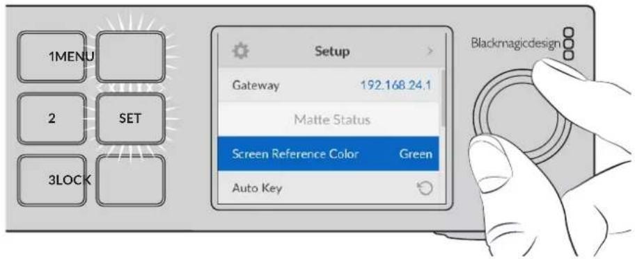
Matte Status
You can use the matte status settings to change the background screen reference color and perform an auto key of your composite.
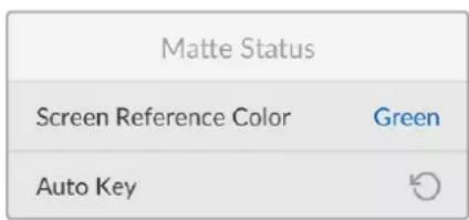
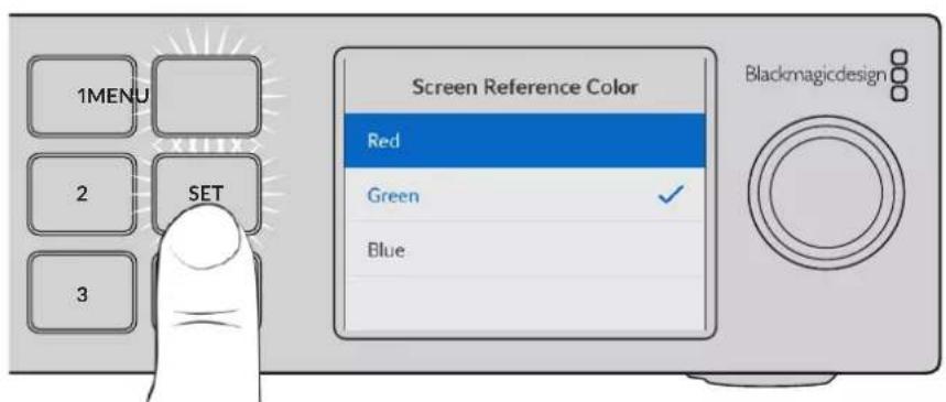
Screen Reference Color
Use this option to select the color of your background. The default color is green.
Auto Key
Use the auto key function to perform a quick composite of your scene. Refer to the 'setting the auto composite' section for more information.
Input Status
The input status display lets you quickly check and confirm which inputs are connected to your Ultimatte and if they are functioning correctly.
| Input Status | |
| Reference | OK |
| Foreground | OK |
| Background | OK |
| Layer | OK |
| Background Matte | OK |
| Garbage Matte | No Input |
| Holdout Matte | No Input |
| Layer Matte | No Input |
| Monitor | No Input |
If 'OK' is displayed next to input, then your Ultimatte is receiving an input correctly. If 'no input' is displayed and you have an input connected, check that your cables are connected correctly and that the input format matches the foreground.
Reset
Highlight 'factory reset' in the setup menu to restore your Ultimatte to factory settings.
| Reset |
| Factory Reset |
Once you press 'set', you will be prompted to confirm your selection. Your Ultimatte erases all settings, preset and the contents of the media pool.
Before performing a factory reset you can export individual presets or create an archive that will contain all presets and the contents of the media pool. Refer to the 'presets' and 'archives' sections for more information.
Controlling Ultimatte
Now that you are familiar with your Ultimatte's front panel, we can begin exploring how to control your Ultimatte and build a composite. There are two different ways to control the unit, such as using the Ultimatte Software Control application on a Windows or Mac computer, or by using the touch screen interface on an optional Smart Remote 4 hardware panel. Both methods use the same general interface so once you are familiar with one, you will also be familiar with the other. The next section of this manual will explore Ultimatte Software Control.
Ultimate Software Control
Ultimatte Software Control gives you full control over all the features and functions of your Ultimatte allowing you to fine tune your composite, change settings, load images into the media pool and control up to eight Ultimatte units over a network. Ultimatte Software Control is compatible with Mac and Windows computers and Smart Remote 4.
Controls and settings are changed using buttons and knobs in the general interface. The settings for each control knob varies depending on which menu you have selected. Additional settings are accessed from the 'Ultimatte' and 'preset' menus at the top left of the screen. If you are using a Smart Remote 4, the physical buttons on the left side of the panel can be used to change these additional settings.
Installing Ultimatte Software
The Blackmagic Ultimatte software includes both Ultimatte Software Control and the Ultimatte Setup application.
Ultimatte Setup lets you update the internal software of your Ultimatte as well as change various settings such as network protocol.
For information on installing Ultimatte Software Control on Smart Remote 4, refer to the 'updating your Smart Remote 4' section.
Windows Installation
1 Download the latest version of the Ultimatte software from www.blackmagicdesign.com/support and double click the installer file.
2 Follow the install prompts and accept the terms in the license agreement and Windows will automatically install the software.
Click the Windows 'start' button and then go to All Programs>Blackmagic Design. The folder will contain both Ultimatte Software Control and Ultimatte Setup applications.
Mac Installation
1 Download the latest version of the Ultimatte software from www.blackmagicdesign.com/support and double click the installer file.
2 Follow the install prompts and Mac OS X will automatically install the software.
A folder called 'Blackmagic Ultimatte' will be created within your applications folder, containing Ultimatte Software Control and Ultimatte Setup.
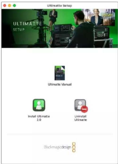
To install Ultimatte Software, double click the Installer and follow the prompts
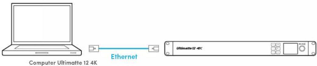
Connecting your Computer
After you have downloaded the software, connect your computer's Ethernet port to your Ultimatte using a CAT 6A or CAT 7 Ethernet cable. For 10G Ethernet ports, we recommend a CAT 7 cable for maximum transfer speed.
For 1G Ethernet ports, connect to your computer using a standard CAT5e or CAT 6 cable. A CAT6 cable will prevent any potential interference from nearby equipment.
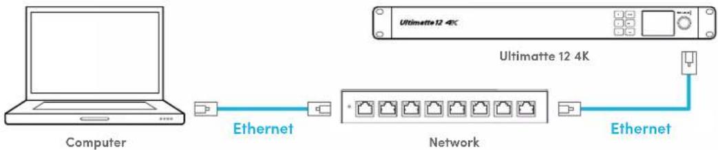
Connecting to an Ethernet switch will allow you to control up to 8 Ultimatte units.
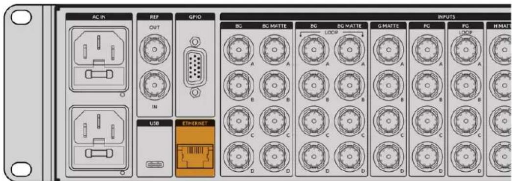
Ethernet port on the rear panel of Ultimatte 12 8K
Connecting Directly
Connecting via a Network
Your Ultimatte unit has a default static IP address of 192.168.10.220. All Ultimatte models except Ultimatte 12 support DHCP so the unit can be found on your network automatically and assigned an IP address. For information on how to manually set the network settings, refer to the 'connecting to a network' section.
Assigning a Unit Number
Once you have connected to a computer or Ethernet switch, launch Ultimatte Software Control. The software will automatically look for connected Ultimatte units.
When launching Ultimatte Software Control for the first time, a window will appear asking for you to assign your Ultimatte unit to a number. This is because up to 8 Ultimatte units can be controlled, therefore the software needs to identify each one. This only needs to happen the first time you connect to Ultimatte Software Control. Once the unit is assigned a number, it will be remembered the next time you launch the software.
To assign the unit:
1 Click in the list for number 1 and select your Ultimatte unit.
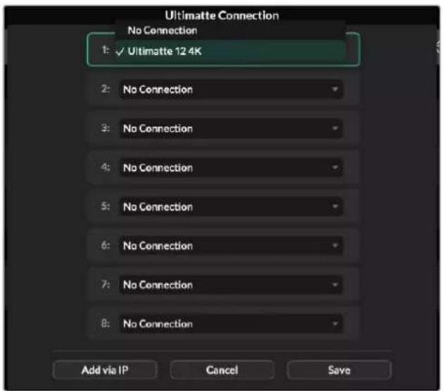
TIP If you are connecting to an Ultimatte 12, click the 'add via IP' button and enter the Ultimatte's IP address.
2 Click 'save'.
Ultimatte Software Control will now display the Ultimatte controls.
You can always assign additional units by clicking on the 'Ultimatte' menu at the top of the screen and selecting 'Ultimatte Connection'.
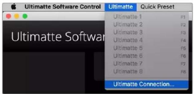
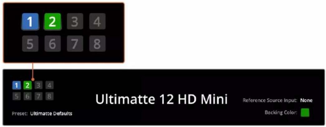
You can see all the Ultimatte units being controlled by glancing at the status bar. Up to 8 units can be controlled, and each unit icon will illuminate green when identified on your network. When a unit is selected for control, the icon will illuminate blue. For more information on how to set up and control multiple units over a network, refer to the 'connecting to a network' section.
Refer to the 'connecting to a network' section for information about how to set up and control multiple Ultimate units on your network
TIP If your Ultimatte is connected to your computer or Smart Remote 4 but its unit indicator is not illuminated in the status bar, check your IP settings are configured correctly. Refer to the 'connecting to a network' section for more information.
Selecting the Ultimatte Main Unit
If you are connected to more than one Ultimatte unit over a network, you can switch between the unit you want to control by clicking the corresponding unit number in the Ultimatte Status bar. You can also use the F1-F8 keys on your computer's keyboard to switch between connected Ultimatte units.
If using a Smart Remote 4 to control more than one Ultimatte, use the 'units' buttons on the left hand side to select the Ultimatte you want to control. Tapping the numbers in the status bar will launch the connection dialogue box.
When selected, the unit icon will illuminate blue and all controls will be visible.
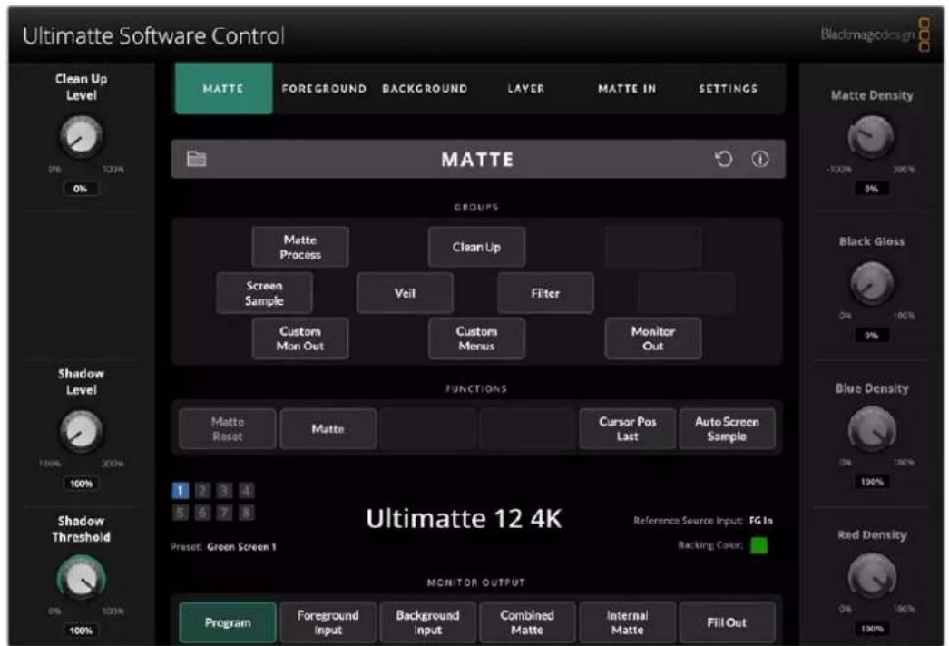
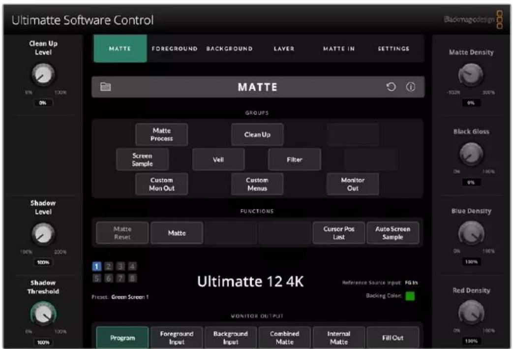
Ultimatte Software Control Layout
Settings and controls are displayed in sections. Although the interface can look intimidating at first glance with all the different buttons and settings, it won't take long before you will be moving between settings instinctively as you build your composite.
When you first look at the interface you can see a main menu at the top with a menu information bar underneath. Below that, the panels are separated into sections labeled 'groups', 'functions' and 'monitor output'. As you choose the menu and then move through the functions and groups, the sections will populate with relevant settings letting you navigate quickly between them.
Main Menu Buttons
Use the menu buttons along the top of the screen to select the different input sources you want to adjust, plus select the matte for making adjustments to the primary matte, and generally configure your Ultimatte.
MATTE
FOREGROUND
BACKGROUND
LAYER
MATTE IN
SETTINGS
Information, File Control and Auto Key
This section of the interface lets you save and access preset files, set an auto composite and configure certain settings for your Ultimatte.

MATTE


Click on folder icon to manage preset and archive files, you can use the dialogue box to save, load, import and export presets. Refer to the 'presets' and 'archives' section for more information.
Use the auto key button to set an auto composite. For more information on setting an auto composite, refer to the 'setting the auto composite' section for more information.
To view status information and various configuration settings for your Ultimatte, click on the information icon.
The available information and configuration settings are described below:
About Displays detailed status information about your Ultimatte including the
model name, software version, video format and network settings.
If you are using a Smart Remote 4, additional information is included, such as:
Remote version
- Flash version
- Temperature
Fan speed
- Blackmagic Design contact information should you need support.
| Configuration | Provides an overview of connected input sources and will tell you whether they are locked or not. |
| Control Board Settings | Lets you customize the brightness of the Smart Remote 4's LEDs and set the internal fan speed. |
| Options Turns the mouse pointer on or off if you have a mouse connected to Smart Remote 4. | |
| Monitor Cascade Enables the monitor cascade feature. | |
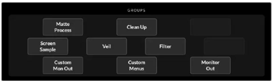
Groups
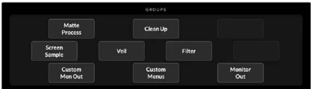
This section of the interface contains the majority of the settings menus. For example, if you wanted to adjust the foreground 'flare' controls:
1 Click on the 'foreground' main menu button to open the foreground settings.
2 Click on the 'Flare 1' button in the groups section to select the flare controls.
The flare controls will now be visible on each side of the panel and you can adjust them using the control knobs.
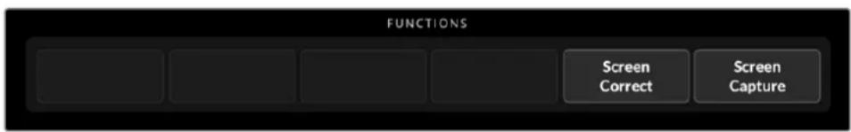
Functions
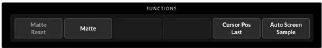
The functions section provides specific settings that can be selected, enabled or disabled. For example, the matte reset button is located in this section if you need to restore particular settings to their default state.
Status Bar
You can see all the Ultimatte units being controlled by Ultimatte Software Control by glancing at the status bar. Up to eight units can be controlled, and each unit icon will illuminate green when identified on your network. When a unit is selected for control, the icon will illuminate blue.
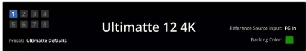
| Ultimatte Main Unit Indicators | The eight small box indicators on the left side show you which main units are connected on the network, and which unit is currently being controlled. If tally is connected via the GPIO input, the boxes will illuminate red when a unit is on air. |
| Reference Source Input | Displays the current reference source connected to your Ultimatte. The reference signal can be from the foreground source connected to the foreground input, or via the reference input. If a reference source is absent, 'none' will be displayed. |
| Backing Color | The default backing color is green and will be reflected by this indicator. When the backing color is changed, the indicator will also change to show the backing color being used. |
| Preset When you have loaded a preset file using the information and file control section, the preset name will be displayed. If no preset is loaded, 'ultimate defaults' will be displayed. In addition, the status bar also notifies you with messages. For example, if a specific control is currently locked and you need to enable another setting to access it, the status bar will notify you. | |
Monitor Out
The buttons in this section of the interface will select one of six images to be displayed on a video monitor connected to your Ultimatte's monitor output.
The default selections are listed below.
| Program Final composited image. | |||||
| Foreground Input Source image connected to the foreground input. | |||||
| Background Input Source image connected to the background input. | |||||
| Combined Matte Internal Matte + Garbage Matte + Holdout Matte. | |||||
| Internal Matte The internal matte created by Ultimatte. | |||||
| Fill Out Foreground image with spill removed, colorizers added, and the screen color suppressed to black. |
Setting Controls
On each side of the interface, you can see a row of setting control knobs. These control knobs will change based on which menu, group and function you have selected.
To adjust a setting, click on a control knob and move your mouse left or right. You can also click in the box below the settings knob and enter a number using your keyboard.
Double click a settings knob to return it to its default position.
Using the Media Pool
The media pool lets you store images and assign them as sources for your composite. You can also add transitions between two still images when they are assigned as a background and background matte or layer and layer matte.
This section shows how to load stills and assign them as sources.
To load a still into the media pool:
1 Open the 'settings' tab in Ultimatte Software Control and click on the media button.
2 Choose 'media setup' from the groups area to open the media pool dialogue box.
3 Click the 'add media' button in the media pool tab and choose the image you want to import.
4 Your imported image will now appear in the device storage list.
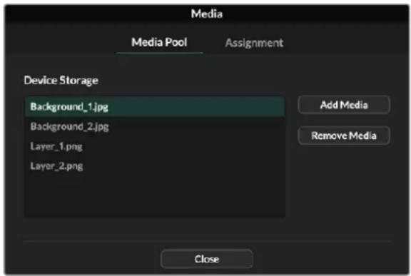
Imported images will appear in the device storage list
To delete an imported image, simply select it from the list and click on the 'remove media' button.
To assign a still image to a source:
1 Select the assignment tab in the media window.
2 Use the destination menu to assign a still image to a background, layer or matte.
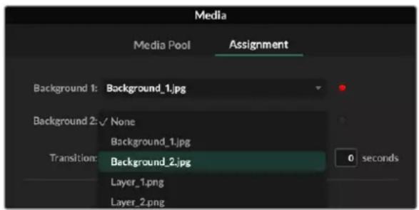
TIP A small red dot to the right of the assignment menu indicates that an image is the current selected source for a background or layer. This helps to make sure that you don't accidentally change a still which is currently on air and makes it easy to identify which still will be used for the next transition.
3 If you are using still images for both the background or layer destinations, then you can choose to add a dissolve transition between the two images. To set the duration of the transition use the transition slider. Dissolve transitions can be between 0 and 10 seconds long in 0.25 second increments.

4 Once you have assigned your still images, click on the 'close' button to close the media window.
To perform a cut or transition between backgrounds or layers you can use the 'background switch' or 'layer switch' button in the function bar of Ultimate Software Control.
TIP When you save a preset your Ultimatte will save any assignments that you have made in the media pool. Keep reading this manual for more information on saving and loading presets.
Supported File Formats for Stills
The Ultimatte media pool can use many different file formats including TGA, PNG, BMP, JPEG and TIFF. Embedded alpha channels are supported in TGA, TIFF and BMP file formats.
Stills Background and Layer Options
Once you have assigned a still image to a background or layer, you have the following options:
- Use the RGB content of the still as a background and use the alpha channel of the still as a background matte. If the still doesn't contain an alpha channel, Ultimatte will assign a solid white matte.
- Use the RGB content of the still as a background and do not use the alpha channel as a background matte. You can do this by disabling the Background Matte In option in Ultimatte Software Control.
TIP Still images used for holdout and garbage mattes need to be grayscale, single channel images.
| Source Supported formats | |
| Background TGA, TIFF, BMP, PNG, JPG | |
| Background and Background Matte TGA, TIFF, BMP | |
| Layer TGA, TIFF, BMP, PNG, JPG | |
| Layer and Layer Matte TGA, TIFF, BMP | |
| Garbage Matte TIFF, BMP, PNG, JPG | |
| Holdout Matte TIFF, BMP, PNG, JPG |
Ultimate Compositing Workflow
Now that you have an auto key established, you can start finressing and refining your composite using Ultimatte's features and settings.
As you refine your composite, it is helpful to move back and forth between monitoring the combined matte view and the program output so you can optimize the matte, plus see how it is working in the final composite.
When adjusting controls, it's worth mentioning that you can restore any control back to its default state by double clicking the respective control. You can also save your workflow to quick presets. As you change settings and make improvements, it's helpful to switch between save points to compare and assess what has changed in order to achieve the best possible settings.
To save a quick preset using Ultimatte Software Control, click the 'quick preset' menu at the top of the screen and choose a save option. To load a quick preset simply choose a load option from the quick preset menu.
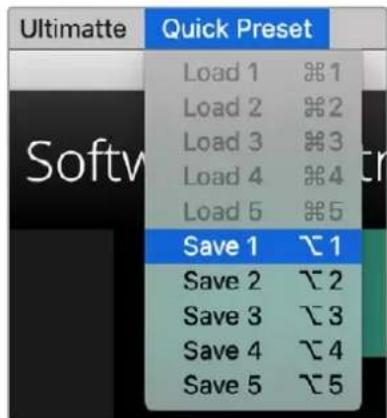
Use the preset menu to save and load quick presets
If your Ultimatte has numbered buttons on the control panel, you can also use these to recall a quick preset.
On Smart Remote 4, hold down the 'alt' button on the left side of the panel and press a quick save button. To load a quick preset, press the desired quick load button.
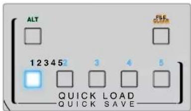
TIP For models with a built in control panel, quick presets are saved in Ultimatte's internal memory, so they will be available after you have power cycled the unit.
On Ultimatte 12 quick presets are saved in volatile memory so they are only available until you power down your Ultimatte.
Quick Guide to Building a Composite
This is a basic introduction to performing a fast composite. You will notice while reading this section that occasionally a feature will be specific to a particular Ultimatte model.
With all sources connected to the main unit, the first step is to make sure the backing color is correctly set. The default backing color is green, but you can set it to red or blue, depending on which color you are using on set.
If you are using a green screen, you don't need to change the backing color as green is already set by default. Clicking the 'auto key' button will perform an automatic composite and generate a matte from your green screen.
TIP An automatic composite will also take place when power cycling your Ultimatte.
Setting the Foreground Backing Color
The backing color defines the color Ultimatte will use to generate the matte. Typically, the color used for most screens for compositing is green, and this is why green is the default backing color. However, there are occasions on set where red or blue may be a better choice based on the color of the foreground objects. In this event, you will need to tell Ultimatte to use a different backing color.
To set the backing color:
1 Click the 'settings' menu button to open the settings.
2 In the functions section, choose the red, green or blue backing buttons to select your desired backing color. You will now see the backing color indicator in the status bar change to the corresponding backing color.
Select a red, green or blue backing color from the functions area.
When the backing color is set, Ultimatte will perform an automatic composite and you will see the results on the program output and Ultimatte's front panel LCD. In the monitor output area, select the program output and the image will appear on the monitor connected to the monitor output.
Setting Screen Correction
Screen correction can be helpful if there are strong variations in your backing screen, or the lighting on the backing screen is uneven.
If your camera is static and you can remove all the foreground objects from the scene, you can perform a screen correction. This shows Ultimatte what the screen looks like by itself, and then once all elements are replaced, Ultimatte can then analyze what has changed in the foreground and will generate an optimized matte. This can help tidy up any areas that are not behaving in your matte.
To perform a screen correction:
1 Remove all the foreground elements in your scene so only the backing screen is visible.
2 Select the 'matte' settings from the main menu buttons.
3 In the 'groups' section, select 'matte process'.
4 In the functions area, click the 'screen capture' button. This stores a snapshot of the green screen which Ultimatte uses to generate the screen correction.
5 Now replace all the foreground elements into your scene.
6 Click the 'screen correct' button.
Your Ultimatte will now analyse the foreground elements against the captured image and determine the optimized matte.
NOTE When using the screen correction feature, it's best to perform this function once the camera is set and in place, because once the camera moves, screen correction will no longer be effective and you will need to reapply the screen correction.
Setting the Matte Density
If the matte needs some refinement, the first step is to adjust the matte density. This improves the black areas of the matte so it is opaque. Any gray areas inside the black matte will cause the background to show through the foreground in those areas.
To adjust the matte density:
1 Select the 'matte' menu button to open the matte settings.
2 Rotate the matte density control knob counterclockwise to decrease the matte density until you start seeing the gray areas inside the black silhouette.
3 Now increase the matte density setting until the gray areas are no longer visible. Be sure to stop adjusting as soon as the gray areas disappear. This is because the least amount of adjustment will result in a more convincing composite. This is true for most controls when refining your composite.
You should now see a near perfect composite on the program output. Now you can use the additional matte settings, foreground, background, and layer settings to refine your composite.
Perfecting your Composite
After your initial key is generated, you may want to add further refinements to make your composite even more convincing. Ultimatte's advanced keyer has powerful tools to let you enhance the composite, perfect the matte edges, color correct each layer, plus blend backgrounds, foregrounds and layers together in very realistic ways. The tools are there for you to use and we encourage you to investigate them and experiment so you can make the most of your Ultimatte and achieve extremely realistic composites.
This section includes a brief outline of the prominent keying and compositing tools available and the order in which they are often used. It's worth mentioning that when adjusting some controls, the smallest change can make best results and you may need to make minor readjustments to some settings as you change others. Achieving the perfect key can be an art form using finesse and dexterity.
1 Matte Adjustments - Further perfect the internal matte using the black gloss settings for eliminating highlights that are keying in the darker areas of the foreground.
As you adjust the matte controls, you may notice a fine white haze over your composite. This is the result of tiny changes to the environment, such as dust accumulating over time, or scuff marks occurring as crew make changes on set. Use the 'veil' settings to help remove the white haze, if the details are too prominent you may also need to clean the set or repaint patches of the blue or green screen.
2 Clean Up Adjustments - Use the clean up settings to remove imperfections in your blue or green screen such as scuff marks, seams, unwanted shadows, electronic noise and screen residue. Adjusting the clean up settings will electronically clean your screen, we recommend using these controls sparingly as they can produce a hard edged, cutout look to the final composited image if used broadly.
3 Flare - Ultimatte performs spill suppression automatically when keying the foreground. Spill is when the green screen reflects onto the foreground elements, causing them to shift their color in unpleasant ways. The flare controls can help refine the spill suppression to further restore the foreground items' original color.
4 Ambiance - Adjust the ambiance controls to add subtle color influences from the background to the foreground layer, helping the foreground subject realistically blend into its environment.
5 Color Correction - Independently adjust brightness, color, contrast and saturation for the different layers in your composite to increase their realistic blend. It's best to make color, brightness and saturation changes to the foreground image using Ultimatte's color correction settings rather than changing camera settings such as lens aperture. This is because any change to the camera will also affect the key.
6 Additional Background and Layer Settings - Use the additional background and layer settings to add elements such as lighting effects to your composition. For example, you can create spotlight effects that shine down on you talent by using an image connected to the layer input that is designed for a spotlight effect. You can then blend that image into the foreground layer.
7 Additional Matte Input Settings - Add additional mattes to your composition, for example a garbage matte to remove unwanted foreground elements from your composition, or a hold out matte to tell Ultimatte to ignore areas of the foreground you don't want to key. You can build a rough window using Ultimatte's 'window' controls in the matte input settings, or assign a custom matte image loaded in the media pool for more precision.
There are many more advanced settings and tools you can use to improve the mattes, strengthen the key, blend layers and generally build and finesse your final composite. Details on how to use all the tools are provided throughout the rest of this manual so you can explore your Ultimatte with confidence.
Advanced Ultimatte Controls
This section contains information about all the settings in Ultimatte Software Control and how to use them to operate your Ultimatte and refine and improve your composite.
Adjusting Matte Controls
Matte Density
As described in the previous section, the matte density setting lets you strengthen the general opacity of the black areas of the matte, preventing areas of the background to show through the foreground. This setting should always be adjusted first when perfecting your composite after applying screen correction. The steps below include the additional steps of switching between the monitor output and the program output so you can see both the matte and the combined composite.
To adjust the matte density:
1 Select 'matte' in the main menu buttons.
2 In the 'monitor out' section, click on 'combined matte'. You will see the foreground subject appear as a black silhouette on a white field.
3 Using the control knob, decrease the matte density until you see details within the black start to become gray. Now increase the setting until the gray areas change to black.
4 Select the program output in the monitor out settings.
Any show through that was present prior to adjusting matte density should now be almost, or completely, gone.
Black Gloss
Sometimes there may be dark areas of your foreground that have bright highlights which are reflecting the backing color. These highlights can appear gray in your matte, which will cause those areas in your foreground image to become transparent in your composite. The black gloss setting helps to remove these areas from the matte.
Increase the black gloss setting while observing the combined matte output until these reflective areas are no longer visible in the matte.
TIP If the matte is already opaque and there are no highlights showing, it's worth decreasing the black gloss level until you see the highlights, then increasing and stopping as soon as they are no longer visible. This is because the lowest setting that can be achieved will result in the cleanest, most convincing composite. This is true for many of the matte controls.
Red, Green and Blue Density
As matte density and black gloss settings are increased, dark edges can form around foreground objects. To compensate, the density of the color channels surrounding the edge of the foreground objects can be adjusted.
For example, if your backing color is green, the colors available to adjust are red and blue. If your backing color is red, the adjustable colors are green and blue. Adjusting these fine color density controls can help clean up dark edges.
Matte Reset
Click this button to restore all the matte controls that affect the foreground elements to their default settings. The matte settings that affect the green screen area, for example clean up and veil settings, will not be changed.
Clean Up Settings
Imperfections in your blue or green screen such as scuff marks, seams, unwanted shadows, electronic noise, and screen residue are visually the same as fine details in the foreground. As a result, these imperfections will also be visible in your final composited picture.
Adjusting the following controls will electronically clean your screen, but at the expense of the finest detail on the edges of the foreground elements. We recommend using these controls sparingly as they can produce a hard edged, cutout look to the final composited image. To determine the best settings, switch your monitor view between combined matte and program out as your make adjustments.
To adjust the clean up settings:
1 While viewing combined matte, the screen area is represented as white. Adjust the clean up controls so that the screen area is as close to white as possible without eliminating important detail.
2 View program out to make sure that you haven't eliminated too much of the fine detail.
The goal is to set these controls to the lowest possible value while ensuring the final picture is not missing subtle details such as fine wisps of hair, shadows, or reflections.
TIP Don't get too focused on getting a perfect clean matte. Some imperfections like slight scuff marks or electronic noise might actually look appropriate in the final composited image, particularly if the background scene is a computer generated, pristine image.
The clean up settings are interactive. Therefore, increasing one might allow you to decrease one or more of the others. You'll notice the greatest effect in the green screen area, but you might also see a slight effect on the foreground elements.
| Clean Up Level Increase or decrease to reduce or eliminate imperfections in the blue or green screen. |
| Clean Up Dark Recover Use this control to recover shadows or edge detail on darker colored elements that were reduced or eliminated by clean up level. |
| Clean Up Light Recover Increase this setting to recover edge detail on lighter colored elements that were reduced or eliminated by clean up level. |
| Clean Up Strength Use this control to add more strength to clean up light recover. |
| Clean Up Reset Click the clean up reset soft button to restore all clean up controls to their default settings. |
Veil Settings
At this point while you are optimizing your matte, you may notice a fine white haze over your final composited image. The haze can sometimes appear as a general haze, or localized in patches corresponding to the screen area of the foreground source.
The white haze is known as 'veil' and you can minimize it by adjusting the veil settings. As you make adjustments, switch your monitor view between fill output and program out to determine the best veil settings.
Master Veil Increase or decrease to remove neutral colored veil over your program or fill output.
Red, Green, and Blue Vell Adjust these controls respectively when you see a colored haze over the program output.
Veiling can become more pronounced over the course of the day as your blue or green floor gets dirtier or dustier. We recommend wearing slippers when not shooting if crew and talent are walking on the blue or green screen. Repainting of the screen may become necessary to remove permanent dirt and marks.
Shadow Level and Shadow Threshold
If you want your shadows in the foreground source to be more or less pronounced in your final composite, increase or decrease the shadow level. The shadow threshold setting is used to help separate unwanted dark screen areas from shadows.
Matte Process/Screen Correction
Depending on the conditions of your green screen, the backing color may not be consistent which can reduce the effectiveness of the matte. If you are seeing noise or artifacts in your matte that you can't solve using the general matte settings, and you have access to an image of just the green screen without foreground objects, then you can use screen correction to improve the matte.
To set screen correction:
1 Remove all the foreground objects in your scene so only the green screen is visible.
2 Click on the 'screen capture' button so Ultimatte can store a snapshot of the green screen.
3 Now replace all the foreground objects in your scene.
4 Click the 'screen correct' button.
You should now see a general improvement in your matte and final composite.
NOTE Screen correction only works with static camera shots. This feature is the best choice for improving areas in the backing screen, and clean up controls can be used as a last resort if areas still need improvement.
Matte Correct Horizontal Size
'Matte correct H size' analyzes all horizontal matte transitions, based on the size selected in number of pixels, and applies the appropriate amount of correction to the horizontal transitions which may need modification.
Unlike regular matte sizing, which slightly reduces the overall size of the matte, the 'matte correct' control selectively corrects only transitions which are not optimally corrected.
The 'matte correct H size' setting indicates the number of pixels within which the system will analyze every transition. When the size is set to 0, no correction is applied.
Matte Correct Vertical Size
'Matte correct V size' analyzes all vertical matte transitions, based on the size selected in number of lines, and applies the appropriate amount of correction to the vertical transitions which need modification.
The 'matte correct V size' display indicates the number of lines within which the system will analyze every transition. When the size is set to 0, no correction is applied.
Screen Sample
When Ultimatte creates the matte for the foreground, it automatically samples the backing color in the foreground image to achieve the best matte. If varying shades remain visible in the matte, you can set your Ultimatte to use single or dual sampling which can help achieve better results.
Single Sampling
Single sampling lets you manually select a single area of the foreground green screen with a small box cursor. Ultimatte then assesses the color in that region and optimizes the sampling of the backing color using that region.
To use single sampling:
1 Go to the screen sample settings in the 'matte' menu.
2 Click the wall cursor position button. Your view will change to the foreground input and a small box cursor will appear on the screen.
3 Adjust the cursor horizontal and vertical position using the control knobs to move the cursor to a spot on the wall near important detail. This can often be hair. Be sure to avoid areas that contain detail that you want to retain.
4 Click the 'sample wall' button to save these screen values as your new reference. Your view will switch back to the monitor out setting you were last using.
Dual Sampling
Depending on the lighting conditions and your green screen, the floor area may appear at a different luminance or shade of green compared to the walls which may affect the quality of your matte when using the default auto sampling or manual single sampling.
To help Ultimatte achieve the best matte, you can select dual sampling and position two separate cursors.
To use dual sampling:
1 Go to the screen sample settings in the 'matte' menu and click on 'dual cursor' to enable dual sampling mode.
2 Click the wall cursor position button. Your view will change to the foreground input and two small box cursors will appear on the screen.
3 Adjust the horizontal and vertical position of the first cursor using the control knobs to move the cursor to a spot on the wall near important detail. This can often be hair. Be sure to avoid areas that contain detail that you want to retain.
4 Click 'sample wall'. Notice that 'floor cursor position' is now enabled and the floor cursor position is automatically available for you to adjust. Make your desired changes to the second cursor position. For best results, select an area on the floor where you see lighting glare or veiling, and avoid shadow areas that you want to retain in the matte.
5 Click on 'sample floor'. Your selection will save these screen values as your new reference and the view will switch back to the monitor out setting you were last using.
Filter
The filter settings let you remove ringing artifacts that may appear in the transition edges, plus provides noise reduction and noise generation settings to help blend foreground and background elements together.
4:2:2 Correction level
In a Y,Cb,Cr 4:2:2 video image, objects with high contrast and sharp transitions can exhibit a small edge artifact when used for green screen compositing. This is due to the reduced bandwidth of the Cb and Cr color difference channels.
For example, a dark colored foreground object with sharp transitions shot against a bright green screen will show an overshoot and an undershoot at the transitions. This is known as ringing. These ringing artifacts are shades of black and white and will be treated as foreground objects when processed, similar to gray strands of hair. When the green screen color is removed and replaced by a dark background, a dark foreground object will show bright gray edges at the transitions.
The 4:2:2 correction feature eliminates or reduces the ringing artifacts. No foreground object detail is lost in this process.
4:2:2 correction is set to 100% by default. To make an adjustment, decrease the setting while monitoring the program output until you notice the ringing artifact appear in the composite, then gradually increase until it is no longer visible.
Noise Reduction/Generation
All video recorded using a video camera will contain a minor level of noise in the image. When composited with pristine, noise free graphics generated by a computer, the difference between sources can be noticeable.
To help blend elements, Ultimatte has noise reduction and noise generation settings that let you clean noise from the foreground, and add noise to the clean areas of your composite. For example, noise can be generated in the background or layer source, or areas of the foreground that have been masked by a garbage matte.
There are two types of noise reduction. Median, and average.
To reduce noise:
1 Toggle between the average and median noise reduction types by clicking the selection button on the left side of the functions section.
2 Now click the corresponding setting next to the selection button to set a noise reduction level. Click multiple times to gradually increase the level. There are four levels of noise reduction to choose from.
To generate noise:
1 Click on the 'noise cursor' button in the functions section to enable the cursor on the foreground source.
2 Using the cursor position controls, place the cursor on an area of the foreground that displays the most prominent noise.
3 Click on the 'noise select' button.
4 Click on the 'noise gen' button to enable noise generation.
5 Increase or decrease the amount of noise generation using the 'noise gen level' control.
Matte Reset
The matte reset button restores all matte controls, including matte density, black gloss, color density, and shadow settings to their default settings. These default settings could be factory set or user set values. For more information on customizing your Ultimatte, refer to the 'saving and managing presets' section.
NOTE Matte reset does not sample the backing for new reference color values. The current values are used to recalculate spill suppression with any adjusted background settings.
Matte Button
Click this button to disable or enable the matte generation and flare settings. The default setting of this button is 'enabled'.
Cursor Position Last
When this button is enabled, the cursor will return to the horizontal and vertical positions where it was last used. This mode is helpful when studio cameras are mounted on robotics systems and could be programmed to go to the same starting position, thus allowing the same exact sampling locations to be used again. When you save a preset file, cursor location is also saved.
When disabled, the location of the cursor will always return to a default horizontal and vertical position toward the top left hand corner of the image, regardless of the previously used sampling location.
Auto Screen Sample
Auto screen sample is the default method of scanning, analyzing, and determining reference backing color levels. Using this method, the matte signal is analyzed to detect the most predominant highest level, which will correspond to the brightest and purest area of the backing. Auto screen sample will also be performed during all of the functions listed below:
Main unit power up, system reset, backing color select, and auto key.
Adjusting Foreground Flare Controls
Your Ultimatte automatically analyzes the backing color reflecting onto foreground objects and removes the effect of the bounce color in the final composite. This is called spill suppression. The process of spill suppression can affect certain colors in the foreground. The colors affected will vary depending on the backing color you are using. If you need to make color adjustments to restore the original color of foreground elements, the results of spill suppression can be adjusted using the flare controls.
Flare 1 Settings
Cool
Restores cooler colors, such as blue, green and cyan.
Skin Tone
Restores the color of natural skin tones that may have been changed by spill suppression.
Light Warm
When advanced flare is enabled, this setting recovers lighter, warmer colors, such as red, yellow and orange. This setting interacts with the skin tones setting.
Black, Gray and White Balance
Use this setting to color correct the spill suppression in the tonal regions of the foreground, such as the shadows, mid tones and highlights.
Flare Level
When advanced flare controls are enabled, this setting adjusts the overall amount of spill suppression for certain foreground colors.
Holdout Matte Flare Button
When a holdout matte is used to stop the compositing process in portions of the foreground scene, spill suppression on the foreground becomes slightly more complicated. In some situations, removing spill suppression from the entire scene would result in a more convincing look. In other situations, no spill suppression in the holdout matte area would be the best choice.
When holdout matte flare is disabled, spill suppression is not performed in the holdout matte region. When enabled, spill suppression is removed from the entire foreground scene.
Flare 2 Settings
Flare Correct Horizontal or Vertical Size
Flare correction analyzes the spill suppression in the transition areas and lets you make subtle corrections. For example, neutralizing small color discrepancies, or luminance variations that may be affecting fine edges in the transition area.
You can adjust the size of the area around the pixels of interest that Ultimatte will use to analyze the spill suppression. This area is defined via pixel width and line height. When the size is set to 0, no flare correction is applied.
Dark Warm
When advanced flare is enabled, this control can help to restore brown colors, for green screen, and purple colors, for blue screen. This control interacts with skin tones settings.
Flare Reset
Click this button to reset all flare controls to their default settings, depending on the backing color selected.
Advanced Flare
Click this button to toggle the advanced flare controls on or off.
Adjusting Foreground Ambiance Controls
To make a composite more convincing, it is important that the foreground subject fits seamlessly into its new background environment. The 'ambiance' feature in Ultimatte analyzes the colors of the background and foreground layers, and automatically adds subtle color influences from the background into the foreground layer. This feature is enabled by default.
The ambiance controls also allow you to set the amount of influence that the background has on the foreground layer, and finesse the color balance.
To make foreground ambiance changes:
1 Select 'foreground' in the main menu buttons.
In the 'groups' section, click on 'ambiance 1' or 'ambiance 2' to access these menus.
Ambiance reset
Click the 'ambiance reset' button to reset all ambiance controls to their default settings.
Ambiance
Use this button to disable or enable the ambiance feature. The default setting of this button is 'enabled'.
Ambiance 1 Settings
The ambiance controls will add very subtle amounts of color from the background, simulating reflected ambient light from the background source.
Ambiance Level Red, Green, Blue
Adjust these settings to increase or decrease effects of the red, green and blue components of the background ambiance that will influence the foreground color levels.
Ambiance Level Master
This setting adjusts the overall level of the ambiance that will influence the foreground color levels. When adjusting this control, the relative difference between the ambiance red, green, and blue components will be maintained.
Ambiance Strength
This setting adjusts the strength of the ambiance that will influence the main area of the foreground subject, compared to the transition areas from the foreground subject to the background scene. At its maximum setting, the ambiance will have full influence on the main area as well as the transition region, while at the minimum setting, the ambiance will have no influence in the main area while having a stronger influence in the transition regions.
Direct Light Mix
This setting controls the proportion by which the foreground subject will be influenced by the ambiance colors and user adjustable direct lighting. At the maximum setting, the foreground subject is influenced entirely by the direct light controls, and at its minimum setting, the foreground subject is influenced entirely by the ambiance colors.
Vertical Blur
This setting determines the number of averaged lines in the background used in ambulance calculations. Depending on the background scene, reducing this control could introduce streaking on the foreground layer.
Ambiance 2 Settings
The direct light controls will make more aggressive changes to the foreground image, simulating light that is directly from a position in the front of the foreground subject.
Direct Light Red, Green, Blue
Adjust these settings to increase or decrease the impact of red, green and blue components of the direct light that will influence the foreground color levels.
Adjusting Brightness, Color, Contrast and Saturation
As you build your composite, you will likely want to make adjustments to the luminance, color, contrast, and saturation levels for your sources which can help improve your composite. For example, if the foreground, background and layer elements seem to differ in levels compared to accompanying composited layers, you can perform an independent color adjustment using the master controls for each source. All the same luminance, color balance, contrast, and saturation settings are available for each source.
White Level Master
If a source seems too bright or too dark for the adjoining scene in the composite, adjust the white level control to alter the brightness of the source rather than adjusting the original input source level. Altering the level at the input source, for example the camera exposure, can adversely affect the generation of the matte signal.
The default setting of the white level control is neutral at 100% . The range of the control is from 0% to 200% . When adjusting the white level master, the relative difference between the white level red, green, and blue components will be maintained.
In normal white range mode the main unit will clip the output so the signal cannot exceed standard limits. All Ultimatte models, except Ultimatte 12 also feature an extended white range mode, in this mode all signals exceeding 100% will pass through unclipped. For more information on output range, refer to the 'settings' section.
Black Level Master
The master black control adjusts the level of black in the source image without altering the white level. Adjusting the black level can often produce a more convincing composite image, if the black levels in the background scene differ from those in the foreground.
When adjusting the black level master, the relative difference between the black level red, green, and blue components will be maintained. Ultimatte will clip black levels at zero so they do not exceed standard broadcast limits.
Contrast Master
The contrast master control adjusts the overall contrast level of the source in the composite without affecting the quality of the composite. For example, if the lighting contrast in the foreground scene does not match that of the background scene, adjusting this control may produce a more convincing composite image.
The contrast setting does not affect the strength of black and white levels, but only changes the contrast of the gamma, or mid level gain, in the source image.
When adjusting the contrast master, the relative difference between the contrast red, green, and blue components will be maintained.
Saturation Master
The saturation master control adjusts the saturation level of the selected source colors without affecting the generation of the matte signal. For example, if the saturation of the colors in the background scene does not appear to match the saturation of the foreground colors, adjusting this control may produce a more convincing composite.
The saturation master control can completely remove all color from the source image and produce a monochrome, or black and white, foreground composited with a color background image.
When adjusting the saturation master, the relative difference between the saturation red, green, and blue components will be maintained.
Advanced Contrast Crossover Master
When the 'advanced contrast' button is enabled in the functions section, contrast adjustment characteristics will acquire an "S" shape curve. The crossover point of the "S" shape can be moved by the source 'contrast crossover' master control.
Fade Control
A fade control is available for the foreground, background and layer sources. This setting lets you fade the foreground or layer source, if enabled, until it is no longer visible.
When the primary matte is disabled in the matte settings, you can use this feature to fade between the foreground source and background source to line up props or set items in the foreground with the background source.
When adjusting the fade or fade-mix control from 0% to 100% , the selected source will gradually fade until no longer visible.
Color Correcting Black and White Levels
The 'black/white level' menu for each background, foreground and layer source lets you make specific color corrections to the black level and white level. By adjusting the respective red, green and blue color correction controls you can adjust each respective color level without altering the overall gain.
TIP Any adjustments to color for the black and white level will only occur after the matte signal generation and will not affect the source.
Adjusting Color Contrast and Saturation
The 'contrast/saturation' menu provides controls to adjust contrast for each color channel in the selected source. Adjusting the contrast control for each channel will increase or decrease the amount of contrast in the gamma, or mid level gain.
When the 'advanced contrast' button is enabled in the functions section, contrast adjustment characteristics will acquire an 'S' shape curve. The crossover point of the 'S' shape can then be moved by the source 'contrast crossover' control. This gives you greater control over how contrast affects the gamma tonal region.
Color Reset
If at any time you want to restore the color correction back to its default state, simply click on the color reset button in the functions section.
Source Freeze Button
If you are working with still graphics as your sources, this feature allows for greater flexibility. You can take a still image from each source by clicking the respective 'freeze' button in the functions section. This stores a still frame in temporary memory which you can use as the source.
The freeze feature can be helpful if you have limited playback equipment. For example, you can save a still from a playback source graphic, then on the same playback deck, load a different source and plug it into a different source input on your Ultimatte. This effectively doubles the amount of sources you can use with your playback equipment.
Additional Background Settings
Background Filter
In many situations, particularly with computer generated backgrounds, the graphics will appear too sharp compared to the foreground subjects. Sometimes, this sharpness can cause aliasing artifacts if the antialIASing filters are not set properly in the background rendering system.
Advancing the background filter control will gradually apply a horizontal low pass filter to the background scene, minimizing aliasing artifacts.
Background Gradient
Enabling this button will replace the background video with an internally generated horizontal gradient signal. This gradient signal can be used to better demonstrate the impact of background color controls on the background image.
Test Signal
This setting lets you use a colored field as the background in the final composite.
Background Switch
If you have still sources assigned to both backgrounds one and two in the media pool, clicking this button will switch between them.
Additional Layer Settings
Test Signal
This setting lets you use a colored field as the layer source in the final composite.
Lighting
Green screens are best optimized when lit flat in neutral light so there are minimal changes in color and brightness. This can add interesting challenges if you want to create lighting effects on the set as the lighting can spill onto the green backing affecting the strength of your key.
As a helpful and convincing alternative, you can use the lighting feature to simulate lighting effects in your composite. For example, you may have pillars of atmospheric spotlights shining down on your talent. By using an image connected to the layer input that is designed for a spotlight effect, you can blend that image into the foreground layer. You can even create an animated image that lets you create dynamic moving lighting effects that are very realistic.
The lighting feature is most realistic when the lighting image used for the foreground lighting effect is also integrated into the background layer when designing your background image. This lets both the foreground and background share the effect which makes the overall simulation more convincing.
To enable the lighting feature, select 'layer' from the main menu and then 'lighting' from the 'groups' menu. Now select 'lighting' from the 'functions' menu.
Lighting Control Knobs
Minimum Level
This control determines a mixture of the level of the 'lighting' input and an internal lighting level setting. The range of the minimum level control is from 0% to 100% , with the default setting at 25% .
At 0% , the lighting of the foreground subjects is entirely controlled by the 'lighting' input image. At 100% , the lighting of the foreground subjects is entirely controlled by the lighting level R/G/B and Master Controls settings.
Color can be added to the Minimum Level by adjusting the Lighting Level Red/Green/Blue and Master controls.
Lighting Level - Red/Green/Blue
This controls the red/green/blue components of the 'minimum lighting' as it is applied to the foreground subjects. The control range is from 0% to 200% , with the default setting at 100% .
Lighting Level - Master
The master control adjusts all three 'minimum lighting' level R/G/B controls simultaneously while maintaining their individual setting relationships.
Layer Color Controls
When the 'lighting' feature is enabled, the 'layer white level, Black Level, Contrast, and Saturation controls will make corresponding adjustments to the Lighting Input image.
For a detailed description of these controls, see Adjusting Brightness, Color, Contrast and Saturation section of the manual.
Layer Input
Enabling this function allows the layer elements to be added to the composite scene.
Layer Input Realistic/Linear/Additive
This function selects between three modes of combining the layer input elements with the foreground objects and the background scene in the composite image.
Realistic
Most accurate method of combining colored transparent and semi transparent layer elements, as well as opaque layer elements, with the foreground objects and the background scene.
NOTE When using a layer source graphic in realistic layer mode with semi transparent objects, the image source background needs to be 100% white. The RGB elements in the source layer should not be premultiplied by its matte. All feathering of transition regions along edges of the matte should be within the boundaries of the layer elements. For example, make sure feathered edges do not extend into the white backing region of the source image.
Linear
Traditional method of combining opaque layer elements with the foreground objects and the background scene in the composite image. This method will not produce accurate results with transparent colored layer elements. This method should be selected if the layer elements are not premultiplied.
Additive
Traditional method of combining opaque layer elements with the foreground objects and the background scene in the composite image. This method will not produce accurate results with transparent colored layer elements and should be selected if the layer elements are premultiplied.
TIP Clicking the auto key' button will not change the layer input mode.
Layer Switch
If you have sources assigned to both layers one and two in the media pool, clicking this button will switch between them.
Matte Input Settings
Blackmagic Ultimatte can accept four different matte inputs, each assigned to a specific function.
These 4 matte inputs are:
- Background matte
- Garbage matte
Holdout matte - Layer matte
Background Matte
The background matte is associated with certain elements in the background scene that need to be treated as their own layer. By converting these background elements into layer elements, they can be moved in the layering order in front of the foreground objects. These background elements that are converted to layer elements can only be opaque elements.
Garbage Matte
The garbage matte is associated with the boundaries of the foreground screen. It is used to artificially extend the screen area, so that the background scene can be added in these areas. The garbage matte should have a large soft transition area, from black to white, so that the garbage matte blends better with the real screen area.
If foreground objects enter these soft transition areas of the garbage matte, these objects will gradually become transparent and mixed with the background scene until they are fully faded out.
In an alternate process, Blackmagic Ultimatte can gradually apply the garbage matte clean up function in the soft transition areas so that the foreground objects can still enter these transition areas without becoming transparent.
Holdout Matte
The holdout matte is associated with elements of foreground objects which have similar colors as the screen color. The holdout matte can be used to prevent these portions of foreground object areas with similar color as the screen from becoming partially or fully transparent.
Additionally, the holdout matte can be used to retain or remove the foreground object colors that are similar to the screen color.
Layer Matte
The layer matte is associated with the 'layer in' elements. The layer matte is used to determine the opacity of the corresponding 'layer in' source. The layer elements associated with the layer matte could be opaque or can have varying levels of transparency with different colors.
Window
The window setting lets you create internally generated mattes with rectangular proportions. The resulting window can be used as a rough garbage matte, allowing you to exclude certain areas from the foreground image. Enable window by clicking the 'window' button, then set the input source you want to apply the window to by clicking the respective matte button in the functions section of Ultimatte Software Control.
Adjust the positioning of the window edges using the following controls:
Window Position Top, Bottom, Left and Right
These knobs adjust the position of the top, bottom, left and right edges of the window. The default position is beyond the edge of the frame. As it is dialed in, the edge moves into the frame and goes all the way to the opposite position of the frame.
Window Softness Top, Bottom, Left and Right
Sometimes you may want to reduce the harshness of a window edge in the garbage matte. To do this, increase the softness control for the window edge you want to adjust. The default position is beyond the edge of the frame. As it is dialed in, the edge moves into the frame and goes all the way to the opposite position of the frame.
Window Skew
The window skew function allows you to create an internally generated window matte with non-rectangular proportions. Using the skew controls, you can tilt and rotate each edge of the window independently to create a rough garbage matte, to exclude certain areas from the foreground image.
Enable window skew by clicking the 'window skew' button, then adjust the skew for each edge using the control knobs.
Adjust the skew of the window edges using the following controls:
Window Skew Top, Bottom, Left, Right
These knobs adjust the skew of the top, bottom, left and right edges of the window.
Window Skew Offset Top, Bottom, Left, Right
As it is dialed in, the skewed window edge moves into the frame and goes all the way to the opposite position of the frame.
Transition Rate
This control sets the rate, in number of frames, by which the objects in the background scene, defined by the background matte and the layer input elements, will move in front of or behind each other in the composited image.
When the transition rate is set to 1, the changes in the layering order will be an abrupt cut. When the rate is increased, the transition will be a smooth mix dissolve. The maximum transition rate is 120 frames.
The transitions are initiated by selecting one of up to six different layering orders defined in the functions section.
Setting the Layer Order
In the functions section you will see buttons that indicate the layer order. These buttons determine the order of how the foreground source, background source, and the layer source elements are arranged in your composite. The buttons available will depend on which mattes you have enabled.
The first name in a button is the top element in the layering order, and the last name is bottom element. For example, you'll notice that the background is always the bottom element in the scene.
When both background matte elements and layer source elements are used, the 6 possible combinations are:
FG/LYIN/BGLY/BG
Foreground source as the top layer, followed by the layer source elements, followed by the background layer elements separated from the background source, then followed by the background source.
LY IN / FG / BG LY / BG
The layer source is the top layer, followed by the foreground source, followed by the background layer separated from the background source, then followed by the background source.
LYIN/BGLY/FG/BG
The layer source is the top layer, followed by the background layer elements separated from the background source, followed by the foreground objects, then followed by the background source.
BGLY/LYIN/FG/BG
The background layer elements separated from the background source are the top layer, followed by the layer source, followed by the foreground source, then followed by the background source.
BG LY / FG / LY IN / BG
In this combination, the background layer elements separated from the background source are the top layer, followed by the foreground source, followed by the layer source, then followed by the background source.
FG/BGLY/LYIN/BG
In this combination, the foreground source is the top layer, followed by the background layer elements separated from the background source, followed by the layer source, then followed by the background source.
When only the background layer is used via a background matte, the 2 possible combinations are:
FG/BGLY/BG
The foreground source is the top layer, followed by the background layer elements separated from the background source, then followed by the background source.
BGLY/FG/BG
In this combination, the background layer elements separated from the background source are in the top layer, followed by the foreground source, then followed by the background source.
When only the layer input is used, the 2 possible combinations are:
FG/LY IN/BG
The foreground source is the top layer, followed by the layer source, then followed by the background source.
LYIN/FG/BG
In this combination, the layer source is in the top layer, followed by the foreground source, then followed by the background source.
Settings
The settings section in Ultimatte Software Control lets you change video settings, access the media pool and make adjustments to the inputs and outputs.
System
The system menu lets you select your Ultimatte's video format, change color space settings and set the 3G-SDI output level.
Video Format
Select your video format from the menu, or set it to 'auto detect'.
3G SDI Outputs
Ultimatte will detect a level A or level B 3G-SDI input automatically. The output is set to level B by default, but you can change it to level A if needed.
To change the 3G-SDI output to level A or B:
1 Go to the 'settings' menu in Ultimatte Software Control.
2 Click on the 'system' button. A window will appear with checkboxes for level A and Level B 3G-SDI.
3 Select the desired level checkbox, then click 'apply' to confirm the setting. Click 'close' to exit the window.
HD/UHD Color Space
All Ultimatte models, except Ultimatte 12 HD Mini support Rec. 2020 color gamut for both HD and Ultra HD. When Rec. 2020 is selected, all input signals must comply with Rec. 2020, and all output signals will conform accordingly. When your Ultimatte detects standard definition, it will automatically set the color gamut to Rec. 601 so you don't have to change the setting when using SD video.
To set the color space:
1 Go to the 'settings' menu in Ultimatte Software Control.
2 Click on the 'system' button. A window will appear with checkboxes for Rec. 709 and Rec. 2020
3 Choose the color space you want to use, then click 'apply' to confirm the setting. Click 'close' to exit the window.
Media
The media button gives you access to the media setup settings. Click the media setup button to open the media pool window, you can then upload still images to the media pool and assign images as sources using the 'assignment' tab. For more information, refer to the 'using the media pool' section.
Inputs
The inputs menu gives you access to the timing controls if you need to delay the foreground input to be syncsed with the background signal and to make subtle timing corrections to a source input signal.
Frame Delay Foreground Input
This control will set the number of frame delays to the foreground input. The control range is from 0 frames to 14 Frames.
In a 4:2:2 signal, the relative timing samples between luma and the chroma, or Y and UV respectively, are well defined. However, some cameras might have some amount of relative luma or chroma timing error. When viewed on a monitor as red, green or blue only, the image will look like an 'embossed' picture. This timing error will cause unnatural transitions and off color edges.
If there are no adjustments in the camera to correct the timing, Ultimatte's inputs menu gives you access to the timing controls if you need to make subtle timing corrections to a source input signal.
Foreground Input U Position
This control will only adjust the U timing relative to Y in sub pixel values. The maximum range of adjustment is +/- 2 pixels.
Foreground Input V Position
This control will only adjust the V timing relative to Y in sub pixel values. The maximum range of adjustment is + / - 2 pixels.
Foreground Input UV Position
This control will adjust both the U and V timing relative to Y in sub pixel values. The relative difference between U and V will be maintained. The maximum range of adjustment is +/- 2 pixels.
Outputs
The output configuration settings let you customize the appearance of the outputs and route certain outputs to help your workflow. For example, setting the talent output to mirror, or routing the monitor output to the program output. Some of the output settings are dependant on the Ultimatte model you are using.
You can also enable the powerful cascade monitoring feature which lets you view the program output for multiple Ultimatte units via one single unit as soon as you select a unit to control in Ultimatte Software Control.
Talent Highlight Level
This control adjusts the amount of highlight applied to the image viewed on the talent output areas where background mattes, garbage mattes, holdout mattes and layer mattes are used.
Matte Out Level
Internal to the unit, the matte signal is set so that fully opaque foreground objects are at 0% black and peak backing areas are at 100% white. The matte out level of 100% white is set at 940 for a 10-bit output. Similarly, 0% black is set at 64.
NOTE The 'matte out invert' function will invert the polarity of the matte out.
The matte out level adjusts the level of the matte out from the white end. This control can lower the matte out level to 0% or push it into the legal ceiling.
Monitor to Program
In most situations, it is advantageous and safe not to be able to switch the program output to other views. However, there are times when the program out view needs to be changed from the composited image to another view. For example, the matte view. For these few instances, it is possible to route the monitor output to the program output.
When 'monitor to program' is enabled, the program output will show the same view selections made in the monitor output. Disabling monitor to program will return the program output to its previous setting.
Fill Linear Mix Correct
If the system you are using to combine the matte and fill outputs does not have an 'additive mix' capability, for example linear mix only, the composite image can have dark edges due to a second processing of the processed foreground image. Enabling the setting marked 'Fill Lin Mix Cor' will minimize potential artifacts caused by the second processing of the foreground image. Use this setting when you are sending the matte and fill to an external device for final mixing, for example a broadcast switcher.
Talent Mirror
Selecting this option will horizontally mirror the program image viewed on the talent output.
The talent monitor output is used for the foreground subjects on the set to see themselves inserted in the new background scene. By providing the capability to horizontally mirror the viewed image, the talent can have a more natural feedback when seeing themselves on the monitor.
Monitor to Talent
When 'monitor to talent' is enabled, the talent output will show the same view selections made in the monitor output. Disabling the monitor to talent will return the talent output view to its previous setting.
Output Range
With normal video signal levels, the maximum white level is specified at 100% , and any signal levels above that level will usually be limited to 100% . In extended video levels, the maximum white level is allowed to exceed 100% .
Ultimatte 12 always uses 'normal white range' mode. All other Ultimatte models use 'normal white range' mode by default, or you can switch on 'output full range' to enable 'extended white range' mode. This applies to the foreground, background and layer inputs and outputs. Matte inputs and matte output maintain normal white range for both modes.
In normal white range mode, any input signal levels exceeding 100% will be clipped to that level at the output. Additionally, color adjustments applied to the video signals, for example white levels, that can take signal levels above 100% will be limited to that level at the outputs.
In extended white range mode, all input signal levels exceeding 100% will pass through the system unclipped. Also, color adjustments applied to the video signals will allow output levels to exceed 100% .
Matte Out Invert
Enabling this function will invert the polarity of the matte out signal.
Output Offset
The output offset control allows you to adjust the output reference timing relative to the foreground or analog reference input to match the timing of various devices in large systems.
Monitor Cascade
The monitor cascade feature can be accessed from the 'information' symbol on the right side of the menu name section of Ultimatte Software Control. You can find the setting under the 'configuration' tab.
When the monitor cascade feature is disabled, the monitor output will be the view selected by the monitor out options. For a single Blackmagic Ultimatte unit, the monitor output can be connected to a video monitor directly. Typically, if there are multiple Blackmagic Ultimatte units, the monitor output for each unit can be connected to a routing switcher for monitoring multiple outputs.
Alternately, with multiple Blackmagic Ultimatte units, they can be daisy chained via their monitor inputs and outputs, with the last unit plugged into a monitor. Then when you select a unit in Ultimatte Software Control, the monitor output for that unit can be viewed on that monitor. This is an efficient and powerful way to monitor the output from up to eight Ultimatte units via one single unit.
To connect four units for cascade monitoring:
1 Connect each Ultimatte unit to an analog reference source or to foreground sources that are locked together.
2 Connect the first unit's monitor output to the monitor input of the second unit.
3 Connect the monitor output of the second unit to the monitor input of the third unit.
4 Connect the monitor output of the third unit to the monitor input of the fourth unit.
5 Connect the monitor output of the fourth unit to a monitor.
When the monitor cascade feature is enabled, the viewed image on the video monitor will be of the unit that is selected in Ultimatte Software Control as the currently active unit. When the unit selection is changed, the image viewed on the video monitor will change to the monitor out of the selected unit.
On Air Settings
The on air settings let you enable on air indicators for the status bar, LCD display and set your Ultimatte to lock its controls when the unit is on air.
NOTE These controls only work when tally signals are connected to the GPIO input and properly configured from the external tally generator on all models except Ultimatte 12 HD Mini. Ultimatte 12 HD Mini can receive tally signals via the HDMI PGM output or SDI Return input.
On Air
When this button is enabled, the unit indicator in the Ultimatte Software Control status bar will illuminate red when on air. The unit identification number above its selection button will also illuminate red.
On Air Lock
When enabled, the on air lock feature will lock all the controls for the unit currently on air. This helps to prevent any accidental changes to a unit that is live on air.
GPI and Tally Settings
These settings enable or disable tally signals when connected to an external GPI and tally interface. Tally lets you monitor on air indicators so you know when an Ultimatte unit is currently on air. GPI inputs and outputs let you trigger Ultimatte preset files as GPI events, similar in nature to loading and running macros.
GPIO MENU
The GPI inputs allow external devices to trigger saved setup files in each input in a predetermined order. The maximum number of events is defined by the number of GPI inputs, therefore the number of events you can use is five.
It is also possible for the main unit to trigger events in other devices using the GPI output. This triggering can be done manually, or upon loading a file if the GPI output was saved as part of that file.
GPI OUT Delay Frames
This control knob sets the delay, in number of frames, between triggering the event and the execution of the GPI output switch closure. The maximum delay is 120 Frames.
GPI Functions Buttons
You can use the GPI functions buttons to add a GPI output to the current workspace settings, toggle between low and high GPI output states and provide a programmable state output.
GPI Output Save
In order to initiate a GPI output upon loading a file, the appropriate instructions must be saved as part of that file. When 'GPI out save' is selected, the instructions to trigger a GPI output will become part of the current workspace settings. When the current workspace settings are saved as a setup file, the instructions to trigger the GPI output are saved with this file.
When the saved file, which includes the triggering instructions, is loaded into the current workspace, the triggering instructions will initiate the proper GPI output sequence.
GPI Out Low/High
Clicking this button toggles the GPI output state between low and high.
GPI Out
This provides a programmable state output, whose width and level are dependent on the GPI out low/high setting and GPI out delay adjustment.
GPI Setup Menu
From the GPI setup menu, you can choose GPI files from the list of previously saved setup files and load them into each GPI input. You can step through each file to verify that the selected files were the correct ones, and that the sequence by which these files were listed was correct. If needed, you can edit each GPI list by removing, adding, or inserting any number of files.
GPI 1 to 5
These windows allows the user to set up the files in the order by which they will be loaded when triggered by the signal connected to each respective GPI input.
Add
With each click, this button will add the highlighted file in the files list to the selected GPI events list.
Remove
Click on this button to remove a highlighted file from the selected GPI events list.
Remove All
This button will remove all the files from the selected GPI events list.
Step
Click this button to move down through the highlighted file selection and automatically load the selected file into the current work space. Any file on the GPI events list can be highlighted and loaded in the current work space by touching the corresponding file name.
Reset
Clicking this button will select the top file from the GPI files list without loading the first file.
The first file will be loaded when the first GPI pulse is detected.
GPI Input Enable
This checkbox enables or disables individual GPI inputs separately based on the setting of the GPI input select control.
GPI High Enable
Enables the software to detect either low to high or high to low transitions of the GPI inputs.
The GPI inputs are triggered by the logic level of the input signal, not by the transition edges. If GPI high enable is checked, the selected input will be triggered by a high logic state. If GPI high is not checked, the selected input will be triggered by a low logic state.
GPI IN Delay
This is a delay between detecting a GPI input and that of actual execution of the GPI list. The GPI input delay can be set at different values for each input. The maximum delay is 120 Frames.
Close
Selecting this button will close the window and exit the GPI setup menu.
Setting Up a GPI Event List
To set up an event list, preset files must be previously created and saved. Refer to the 'saving and managing presets' section for more information.
1 Click on the 'settings' menu button and select GPIO in the groups section. Click the GPIO setup' button and the GPIO setup window will be displayed.
2 From the tabs, select a GPI number from 1 to 5 to be used. If the selected GPI number was used before, the event list will show the previously selected files. The existing event list can be edited by removing, adding or inserting files. Alternately, select 'remove all' to remove all the files from the event list.
3 Select the file to be added to the event list. When selected, the file will be highlighted.
4 Click on the 'add' button to add the file to the event list.
5 To add more files to the event list, repeat steps 3 and 4.
When the event list is complete, click 'reset' to move to the beginning of the event list. Adjust GPI input delay if necessary. This is the delay, in frames, when loading the files from the time the GPI pulse is received.
1 For high GPI input logic state, select the 'GPI high enable' checkbox. Leave deselected if using a low logic state.
2 Enable GPI by selecting the GPI input enable checkbox.
3 Repeat these steps for each GPI input.
To edit an existing events list:
1 Select the GPI event number to be edited.
2 Select a file to be deleted by choosing the file name and clicking the 'remove' button.
3 To insert a new file into the event list, select the file below the area in the list you want to insert the new file. Now click the 'insert' button.
4 When editing is completed, click 'reset' to select the beginning file of the event list, then click 'close' to exit the GPI setup window.
GPIO Pinout
The female GPIO connector on your Ultimatte's rear panel is a DE-15 connector. If you want to build a cable for your own custom GPI and tally solution, a pinout chart is provided below.
| GPIO PIN CONFIGURATION | |
| Signal Input Pins | Return Output Pins and Ground Pin |
| 1 = GPI 0 6 = GPI 0 R | |
| 2 = GPI 1 7 = GPI 1 R | |
| 3 = GPI 2 8 = GPI 2 R | |
| 4 = GPI 3 9 = GPI 3 R | |
| 5 = GPI 4 10 = GPI 4 R | |
| 11 = Tally 12 = Tally R | |
| 13 = GPO 14 = GPO R | |
| 15 = GND | |
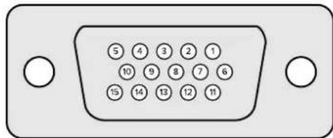
Monitor Out Settings
This selection will show all the viewing options available. The button name will be changed to 'return' which you can click on to go back to the previous menu. Monitor out settings configure the output from the 'monitor out' connector.
Monitor Highlight Level Control
This control adjusts the amount of highlight applied to the image viewed on the monitor output in the areas where background matts, garbage matts, holdout matts and layer matts are used.
Monitor Setting Buttons
The monitor setting buttons allow you to change the matte view and select individual color channels to view independently.
Matte View Range
The quality of images viewed on video monitors depends on the monitor's brightness and contrast setup. In many situations, the detail information in the very dark and very bright portions of an image is sacrificed so that the rest of the image can have a more pleasant look. The levels in a matte image cover the whole brightness gamut and most of the matte controls are adjusted while observing matte levels near the darkest or the brightest end.
For this reason, it is difficult to adjust the matte accurately while looking at a monitor and observing the darkest and brightest portions of the images.
Enabling the 'matte view range' function will raise the black level and reduce the white level of the matte signal so that detail information in the blackest and whitest sections of the matte can be viewed accurately on a monitor.
Reducing the range of the matte on the monitor output has no effect on any internal processing or the signal levels of the matte out.
Matte View Invert
When combined matte view or internal matte view is selected as the monitor output, the matte polarity can be reversed by the matte view invert function.
Monitor Out RGB
When selected, the monitor output will show all three color channels of the image viewed.
Monitor Out Red, Green and Blue
All three color channels can also be viewed independently. When the respective color channel button is enabled, the monitor output will only show that particular color channel as a black and white image. This can be helpful to spot noise, which is predominantly in the blue channel.
Custom Monitor Output Menu
The monitor out section of Ultimatte Software Control provides six soft buttons which switch the view on Ultimatte's monitor output. These six soft buttons can be customized using the 'custom monitor out' settings.
The first two soft buttons in the functions area of the interface are labeled 'standard' and 'inputs'. These let you set the labels of the buttons to the standard default Ultimatte monitor output buttons, or you can match the buttons to the respective inputs. When inputs is selected, you can easily monitor every source by clicking the respective input button.
Below is the configuration for each setting:
| Standard | Inputs |
| PGM Out | BG In |
| FG In | Layer In |
| BG In | BG Matte In |
| Combined Matte | Garbage Matte In |
| Internal Matte | Holdout Matte In |
| Fill Out | Layer Matte In |
You can also create up to four custom monitor out buttons. These can be set to show your favorite views in the order of your choosing.
To configure a custom monitor output button:
1 In the 'matte' settings, click the 'custom monitor out' button in the groups Section.
2 Click on the 'configure' button in the groups section.
3 In the dialog box, select any of the tabs labeled MONITOR OUT 1, 2, 3, and 4.
4 From the menus, choose which of the following potential monitor outputs you would like to assign to each of the buttons. You do not necessarily need to assign a function to each button. If 'none' is chosen, that button will appear blank.
- Program - Garbage Matte In
FG In Holdout Matte In - BG In -Layer matte in
- Combined matte - Processed L M. Layer matte with adjustments applied.
- Internal matte - Processed H M. Holdout matte with adjustments applied.
- Fill Out - Processed G M. Garbage matte with adjustments applied.
- Layer In - Processed B M. Background matte with adjustments applied.
- Background matte in - Screen correction capture. Image captured and used for screen correction function.
5 Click on 'apply' to save your choices.
To load a custom monitor configuration, select 'custom monitor out' in the groups section, and then choose one of the custom monitor buttons.
Presets
Presets make it easy to quickly save and recall setup and composite settings for your Ultimatte. Presets are interchangeable between all Ultimatte models with a built in LCD.
TIP When you save a preset your Ultimatte will also save any image and video assignments that you have set in the media pool. For example, you can save presets 1 and 2 with different still image backgrounds and save preset 3 with a live video background, then cut between the backgrounds using the preset buttons on your Ultimatte's front panel.
Saving and Managing Presets
Clicking the folder symbol in the files and information section of Ultimatte Software Control opens the presets window.

SETTINGS


The preset window gives you access to all the preset management functions on your Blackmagic Ultimatte including saving, loading, exporting and assigning presets to 'quick preset' shortcuts.
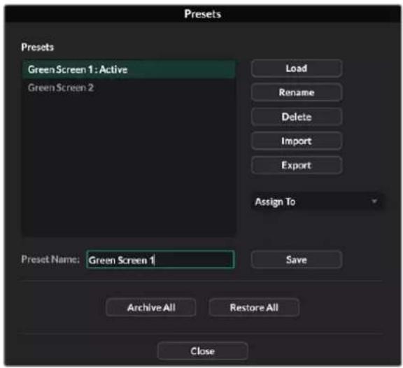
The preset window in Ultimatte Software Control
To save a preset:
1 Once you have a foreground source connected to your Ultimatte and have adjusted your composite parameters, click on the file icon to open the presets window.
2 In the 'preset name' field, type in a name for your preset and click the save' button.
3 The saved preset will appear in the presets list.
To delete a preset:
1 Select the preset you want to delete from the list of saved presets.
2 Click on the 'delete' button and confirm your choice.
To load a preset:
1 Select the preset you want to load in the saved presets list.
2 Click the 'load' button. In the saved preset list, 'active file' will now appear next to the loaded preset.
Renaming a preset:
1 Select the preset you want to rename from the saved presets list. The current preset name will appear in the 'preset name' field.
In the 'preset name' field, type in a new name for the preset. Click the ' Rename' button.
Assigning presets
You can assign up to five presets to 'quick preset' shortcuts. This lets you access presets quickly using the 'quick preset' menu in Ultimatte Software Control or by using the numbered buttons on units with built in LCDs. You can also recall presets using the 'quick load' buttons on Smart Remote 4.
To assign a preset to a quick preset shortcut:
1 Select a preset from the preset list.
2 Use the 'assign to' menu to assign the preset to a quick preset shortcut.
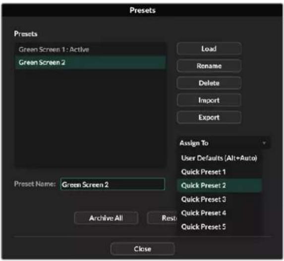
Use the 'assign to' menu to assign preset to quick preset shortcuts.
Importing and Exporting Presets
On all models except Ultimatte 12, you can import and export presets to and from your Ultimatte. This can save time if you are setting up multiple Ultimatte's and want to make sure that the composite parameters are the same across all the units.
To export a preset:
1 Click on the folder icon in the files and information section of Ultimatte Software Control to open the presets window.
2 Select the preset you want to export from the saved preset list.
3 Click the 'export' button and choose a destination to saved presets list. Click 'save'.
To import a preset:
1 Open the presets window.
2 Click on 'import'.
3 In the dialogue box, navigate to the preset you want to import. Click 'open'.
4 The imported preset will appear in the saved presets list.
Archives
An archive is a backup of your Ultimatte that includes its current state, all settings, presets and the contents of the media pool. Creating an archive of your Ultimatte is useful if you regularly switch between different productions or if you are setting up additional Ultimatte units.
Archives are interchangable between Ultimatte models.
Creating an Archive
To create an archive click the folder symbol in the files and information section of Ultimatte Software Control, this will open the preset and archive window.

1 At the bottom of the preset and archive window click the 'archive all' button.
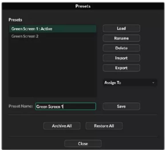
2 In the dialogue box choose a destination for your archive and type in a name. Click 'save'.
Your Ultimatte will now start creating the archive and display a progress bar. Once complete, the archive will appear as a .zip file on your computer.

Restoring an Archive
To restore an archive, click the folder symbol in the files and information section of Ultimatte Software Control.
1 At the bottom of the preset and archive window click the 'restore all' button.

2 In the dialogue box navigate to the archive file that you want to restore. Click 'open'.
3 Your Ultimatte will now start restoring the archive and a progress bar will be displayed.
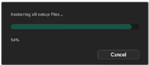
When the restore is complete the settings, presets, quick presets, GPI settings and media pool stills will be available on your Ultimatte.
Customizing the Menu
You can change the assignment of the Ultimatte Software Control and Smart Remote 4 control knobs and buttons in the 'settings/custom menus' settings.
To set a custom menu:
1 Go to the 'settings' menu.
2 Click on the 'custom menus' button.
3 Choose one of the four custom menu presets you want to set.
4 A new 'configure' button will appear just above the custom menu preset buttons. Click this 'configure' button. The custom menu setup dialog box will appear.
The control knob functions are in the left side column, and you can set a function from that column to each of the eight slots on the right side column. The eight slots correspond to the control knobs as follows:
Item 1 = Top left control.
Item 2 = Left second control down.
Item 3 = Left third control down.
Item 4 = Left bottom control.
Item 5 = Top right control.
Item 6 = Right second control down.
Item 7 = Right third control down.
Item 8 = Right bottom control.
To assign functions to each control knob:
1 From the 'knobs' list, scroll up and down the list of functions and select a function from the list.
2 Click on the right arrow icon in the middle column that corresponds to the desired slot. You will see the name of the selected control appear in the blank slot.
TIP If you change your mind and want to assign a different function to that slot, simply click the left arrow to remove that function from the slot and assign a different function.
3 Repeat steps 1 and 2 as you progress through all the slots to assign your custom functions to each control knob.
4 Click on the 'buttons' tab to assign the buttons. Follow the same procedure as shown above to set the buttons controls.
5 When you are happy with your selections, click 'apply'.
You will now see all your customized controls on the interface.
If you are moving through other menus and want to return to your custom menus, you can enable them by clicking 'custom menus' in the groups section, then press the desired custom menu button. You will now see all the controls and functions buttons change back to your custom selection.
Camera Control via Ultimatte 12 HD Mini
Connecting Ultimatte 12 HD Mini to a Blackmagic Pocket Cinema Camera and an ATEM switcher lets you maintain camera control and tally.
Connecting via HDMI
1 Plug your Blackmagic Pocket Cinema Camera's HDMI output into Ultimatte 12 HD Mini's Camera FG HDMI input.
2 Connect the HDMI PGM OUT of your Ultimatte 12 HD Mini into the corresponding HDMI input on your ATEM switcher. We recommend matching your cameras with their corresponding input number. For example, camera 1 to input 1 and camera 2 to input 2.
HDMI is bidirectional so tally and camera control data is sent back to your camera using the same HDMI cable.
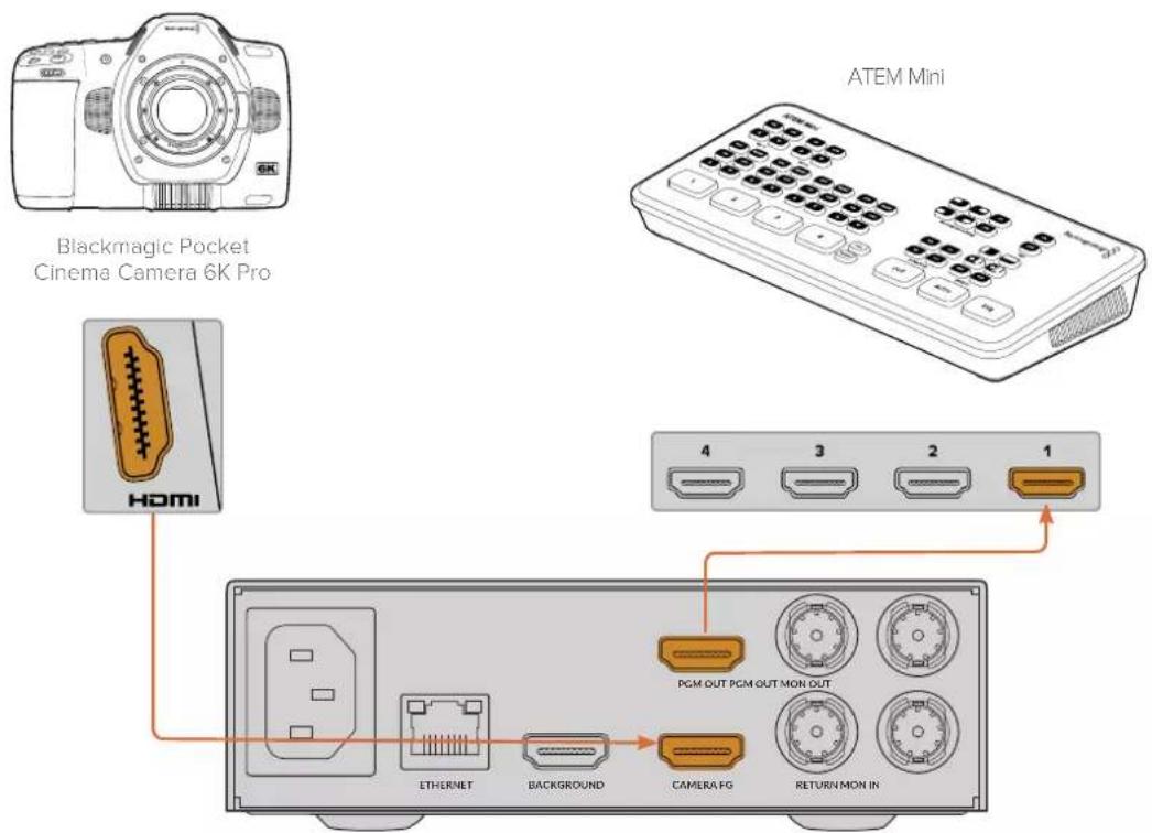
Blackmagic Ultimatte 12 HD Mini
Connecting via SDI
1 Plug your Blackmagic Pocket Cinema Camera's HDMI output into Ultimatte 12 HD Mini's Camera FG HDMI input.
2 Connect the SDI PGM OUT of your Ultimatte 12 HD Mini into the corresponding SDI input on your ATEM switcher.
3 Using a second SDI cable, connect an output from your switcher to the SDI return input on Ultimatte 12 HD Mini.
Blackmagic Pocket Cinema Camera 6K Pro
ATEM 2 M/E Constellation HD
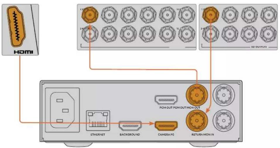
Blackmagic Ultimatte 12 HD Mini
4 Open Blackmagic Ultimatte Setup on your computer and set the camera ID in the 'camera control' section of the 'setup' tab.
The camera ID number should match both the input number on your ATEM switcher and the camera ID number in your camera's menu. This ensures camera control and tally is sent to the correct camera from the ATEM switcher.
SDI Return Camera Control
ATEM Camera ID:
1
Set the camera ID in Blackmagic Ultimatte Setup
Connecting to a Network
Your Ultimatte main unit is shipped with a default IP address of 192.168.10.220 but you can change this address if you need to. This is important when sharing multiple Ultimatte units on your network and controlling them using Ultimatte Software Control on your computer or a single Smart Remote 4.
TIP If you are connecting to more than one Ultimatte unit of the same type, it's a good idea to give each unit a discreet name to make them easy to identify. For more information, refer to the 'Blackmagic Ultimatte Setup' section.
Setting the IP Address
You can change the IP address for an Ultimatte main unit using the front panel LCD menu or Blackmagic Ultimatte Setup software. For more information on using the front panel menu, refer to the 'using the LCD menu' section.
To download the latest Ultimatte Setup software go to the Blackmagic Design support center at www.blackmagicdesign.com/support. For installation information refer to the 'installing Blackmagic ultimatte software' section in this manual.
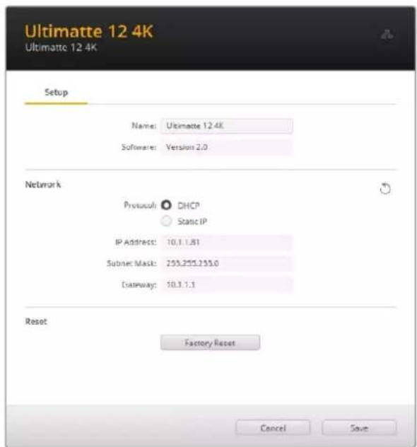
The 'setup' tab of Blackmagic Ultimatte Setup has default settings for static IP and a 'DHCP' option
To change the IP address using Blackmagic Ultimatte Setup:
1 Connect the desired Ultimatte main unit to your computer via USB.
2 Launch Blackmagic Ultimatte Setup.
3 Click on the unit icon for your Ultimatte to open the setup settings.
4 In the 'setup' tab, enter the IP address, subnet mask and gateway settings.
On all Ultimatte models except Ultimatte 12, you can enable DHCP instead of assigning an IP address manually. DHCP is a service on network servers that finds your Ultimatte and assigns an IP address automatically. DHCP makes it easy to connect equipment via Ethernet and make sure their IP addresses do not conflict with each other.
5 Click 'save' to confirm the settings.
Repeat the same process for each main unit you want to control. The subnet mask and gateway should match your network settings and stay the same between all units, but make sure each unit has its own unique IP address.
Setting the IP Address for your Smart Remote 4
If you are using a Smart Remote 4 and have updated each Ultimatte main unit's IP address, you will need to configure the IP address on Smart Remote 4 so you can control the main units on your network.
To set the IP address on your Smart Remote 4:
- Reveal the Windows desktop by tapping on the info icon in the Smart Remote touchscreen information and file control section. Now tap on the 'options' settings and tap exit to desktop.
2 Navigate to the Windows network settings.
3 In the Ethernet related settings, select 'change adapter options'.
4 Double tap on the 'Ultimatte' network to open the Ultimatte status window.
5 Tap on 'properties'.
In the properties window, double tap on 'internet protocol version 4 (TCP/IPv4) to open its setting properties.
7 Select the 'obtain an IP address automatically' setting to let your Smart Remote find its own IP address to join the network you are connected to. Or if you want to enter the IP address, subnet mask and default gateway settings, select 'use the following IP address' and set it manually.
8 Tap 'OK' to confirm the settings.
Double tap on the SR4 smart remote software icon to return to the touchscreen control panel.
Assigning Unit Numbers
Now that you are ready to control your Ultimatte main units, you need to assign them unit numbers in the Ultimatte connection window.
To assign a number:
1 In Ultimatte Software Control, open the 'ultimatte connection' window from the top menu bar. If you are using a Smart Remote 4, tap on a unit ID number.
2 In the ultimatte connection window click in each unit number list and select the name of the Ultimatte that you want to allocate to that unit number.
TIP If you are connecting to any Ultimatte 12 units, click the 'add via IP' button and enter the Ultimatte's IP address.
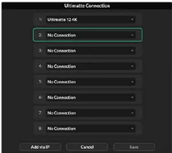
3 Click 'save' to confirm your selection.
If you look at the status bar, you will now see that unit number illuminated green. This means the unit is online and ready to be controlled.
Blackmagic Ultimatte Setup
Blackmagic Ultimatte Setup is used to change settings and update the internal software in your Ultimatte.
To use Ultimatte Setup:
1 Connect Ultimatte to your computer via USB or Ethernet.
2 Launch Ultimatte Setup. Your Ultimatte model will be named in the setup utility home page.
3 Click on the circular 'setup' icon or the image of your Ultimatte to open the setup page.
Setup Page
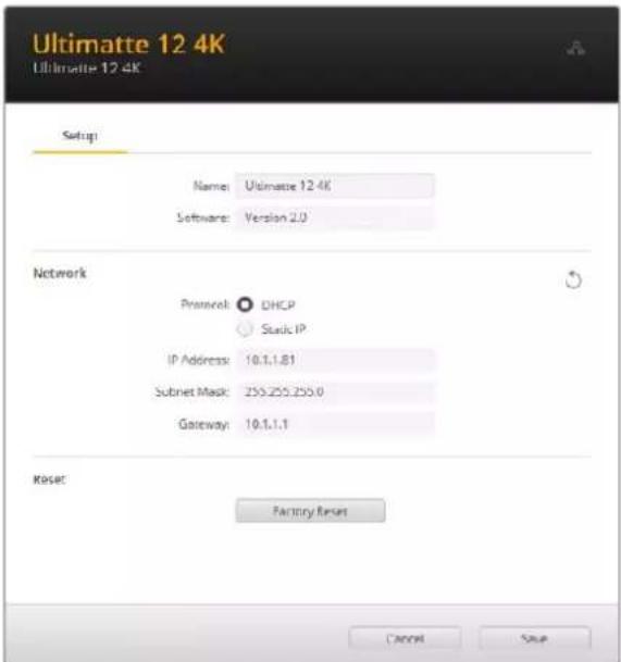
If you have more than one Ultimatte, you may wish to give each unit a discrete name to make them easy to identify. You can do this via the 'name' option.

Network

These settings allow you to configure options such as choosing between connecting to a network over DHCP or using a static IP address. For more information on connecting your Ultimatte to a network, refer to the 'connecting to a network' section.
Reset
Reset your Ultimatte by clicking the 'factory reset' button. This will return your Ultimatte to its original factory settings, any stills saved in the media pool will be deleted.
Updating the Internal Software
The setup utility lets you update your Ultimatte's internal software in addition to configuring the network settings.
To update the internal software:
1 Download the newest Blackmagic Ultimatte Setup installer from www.blackmagicdesign.com/support.
2 Run the Blackmagic Ultimatte Setup installer on your computer and follow the onscreen instructions.
3 After installation is complete, connect your Ultimatte to your computer via USB or Ethernet.
4 Launch Blackmagic Ultimatte Setup and follow any onscreen prompt to update the internal software. If no prompt appears, the internal software is up to date and there is nothing further you need to do.
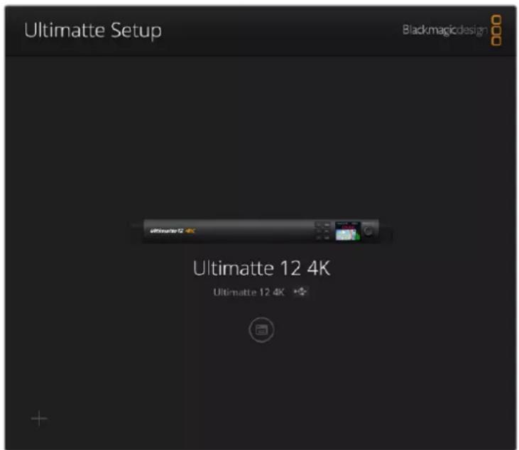
Download the latest setup utility for your Blackmagic Ultimatte from the Blackmagic Design support center at www.blackmagicdesign.com/support
Using Smart Remote 4
If you are using an optional Smart Remote 4 to control your Ultimatte, you will first need to install the latest version of Ultimatte Software Control. For more information, refer to the 'updating your Smart Remote 4' section.
Connecting Power
Plug the included power adapter into the DC power input on the rear panel. The screw ring is used to secure the connector to the port.
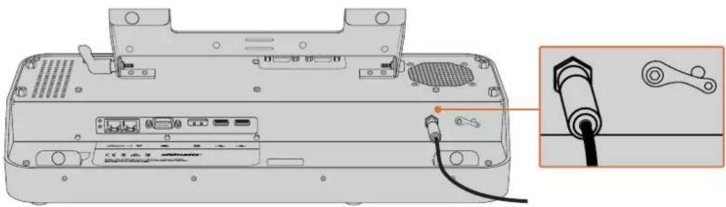
TIP The power adapter's outside screw ring also serves as the negative contact, with the positive contact being the center pin of the connector. If you want to secure a ground connection to the chassis of your Smart Remote 4, you can attach it to the terminal lug located next to the power input.
Connecting to Ultimatte
Connect an Ethernet cable from the rear panel of your Ultimatte to the left side Ethernet port of Smart Remote 4.
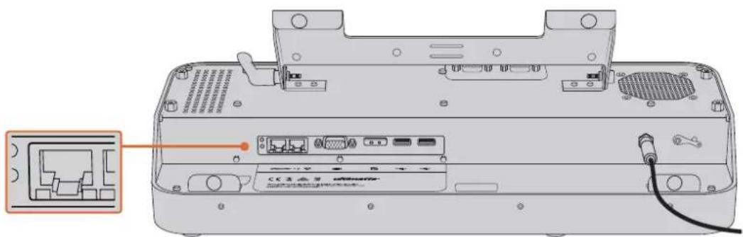
Plug your Ultimatte main unit into the Smart Remote 4's left side Ethernet port
Turning on Smart Remote 4
To turn the smart remote on, press the power button located at the top left corner of the control panel.
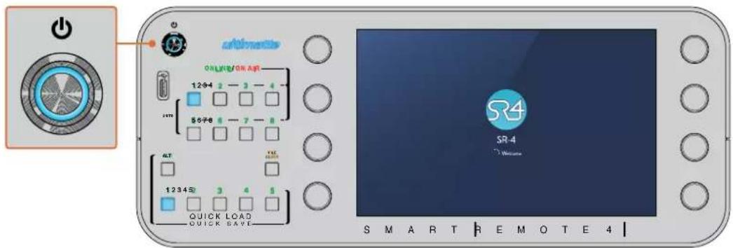
When power is activated, the power button will illuminate blue and the smart remote will initiate the software start up sequence
At its heart, Smart Remote 4 is a small portable computer running the Windows® operating system. When the start up sequence is complete, the Ultimatte Software Control will launch and the control panel will appear on the touchscreen.
Updating your Smart Remote 4
The first step to updating your Smart Remote 4 is to uninstall the SR4 software from your smart remote.
Tap on the 'info' icon in the Smart Remote 4 file control section of the control panel to find your current SR4 software version number. Follow the sections below based on whether you have SR-4 v1.0.5 or earlier or if you have SR-4 v1.1 or later.
Uninstalling Software
Before uninstalling the SR4 software, ensure the application is not running.
To quit the SR4 software:
1 Tap on the 'info' icon in the smart remote 4 file control section in the control panel.

In the 'options' tab, tap on the 'exit to desktop' button.
3 Now that the desktop is visible, tap on the 'up' arrow in the Windows tray.
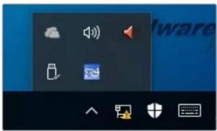
4 Tap and hold the Ultimatte SR4 icon for 2 seconds then release. The 'quit' icon will appear. Simply tap on the 'quit' icon to close the application.
To uninstall SR4 v1.1 or later:
1 Press the 'start' button in the task bar and select 'settings'.
2 In the settings window, select 'system' from the menu and choose the 'apps & features' option.
3 In the 'apps & features' window, scroll through the list of apps and locate the Ultimatte SR4 software.
4 Select the Ultimatte SR4 software from the list and choose 'uninstall'.
5 Follow the prompts to uninstall the software.
To uninstall SR4 v1.0.5 or earlier:
1 Tap and hold the Windows logo in the bottom left corner, then tap on 'file explorer'.
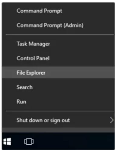
Tap and hold on the Windows logo, then tap file explorer
2 In file explorer, navigate to: C:\Program Files\Ultimatte\SR4, and double tap on the maintenance application labelled, 'maintenancecetool.exe'
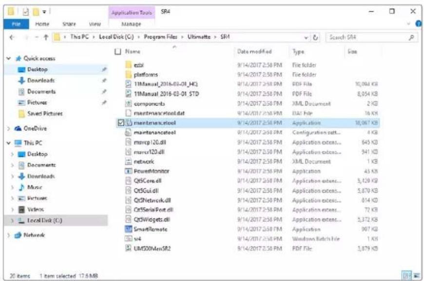
Browse 'local disk C:\' and double tap on the required folders to open their contents
3 On the maintenance application window, select 'remove all components' and tap 'next'.
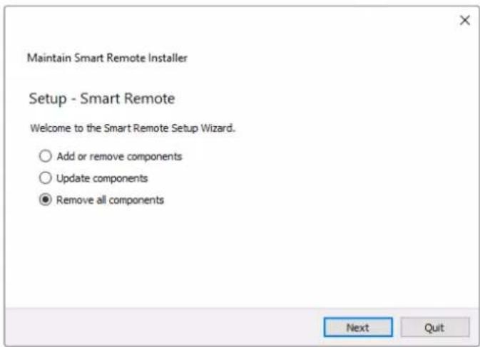
Select 'remove all components' and tap 'next'
4 The maintenance application will now let you know it is ready to uninstall. Tap 'uninstall' and allow the application to make changes to your Smart Remote 4 by tapping 'yes'.
5 Tap 'finish' on the 'completing the smart remote wizard' window.
The Ultimatte Smart Remote 4 software has now been uninstalled.
Installing Ultimatte Smart Remote Setup
The first step is to download the latest Ultimatte Smart Remote 4 Setup software from the Blackmagic Design support center at www.blackmagicdesign.com/support. Copy and paste the Smart Remote .msi file onto a portable USB storage unit, for example a USB flash drive.
Plug the USB drive into the USB port on the front of your Smart Remote 4. Smart Remote 4 will automatically read the USB drive and open the file explorer.
NOTE The portable storage drive used to install the software on your smart remote must be formatted as the master boot record using one single partition. Your Smart Remote 4 recognizes NTFS, exFAT and FAT32 formats.
To install the software:
1 Double tap on the smart remote installer icon in the storage drive.
2 Tawp 'next' in the setup wizard and follow the prompts until you reach the 'install' option.
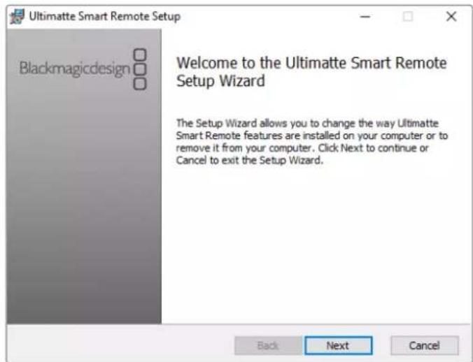
3 Tap 'install' and allow the installer to make changes to your Smart Remote 4 by tapping 'yes' when prompted.
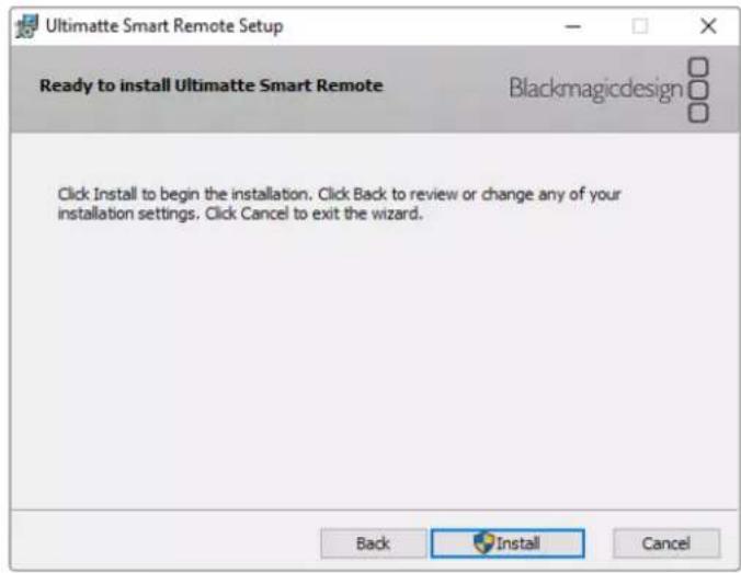
4 Tap 'finish' to complete the installation and 'yes' to restart your Smart Remote 4. Your Smart Remote 4 will restart and automatically launch the latest version of the Ultimatte Smart Remote 4 control panel.
5 A Windows dialogue box will appear prompting you to allow Smart Remote to communicate over a network. Select 'private networks, such as my home or work network' and tap 'allow access'.
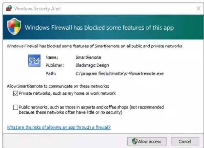
Connecting a USB Keyboard and Mouse
If you want to control your Ultimatte Smart Remote 4 using a keyboard and a mouse, simply plug them into the USB ports on the rear panel. Your Smart Remote 4 will automatically detect the keyboard and mouse as a plug and play device and you can control your Smart Remote 4 as if using a Windows PC.
Rack Installation
Ultimatte 12 8K and 4K models can be installed into a broadcast rack or road case using the included Ultimatte rack mount kit.
If you are using your Ultimatte on a desk, you can fit the supplied rubber feet to the base. Simply stick a rubber foot to each corner of the underside, taking care not to cover any screws
The rack mount kit contains the following items:
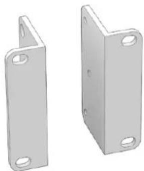
2 x Front Rack Ears
Attach the front rack ears to the outside front edge of the unit.
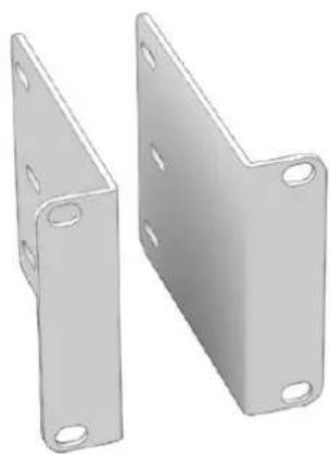
2 x Rear Rack Ears
Attach the rear rack ears to the outside rear edge of the unit.
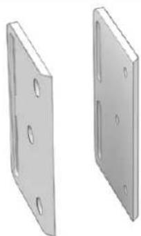
2 x Chassis Bumpers
Two chassis bumpers can be attached to each side of the chassis. These bumpers are designed to protect the rear connectors.
They can also provide strain relief for cables that are connected to the unit.
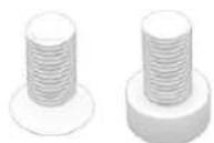
Screws
12 x M4 Countersunk 6 x M4 Flathead Screws
For front rack ears and chassis bumpers
For rear rack ears
Installing Front Rack Ears
Using a 2mm hex key, attach the rack ears to each side of the unit using the supplied M4 countersunk screws.
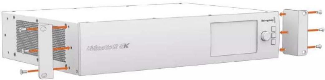
Installing Rear Rack Ears
Using a 3mm hex key, attach the rear rack ears to Ultimatte 12 8K using the supplied M4 flathead screws.
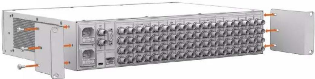
Installing Chassis Bumpers
Install the optional chassis bumpers using the supplied M4 countersunk screws.
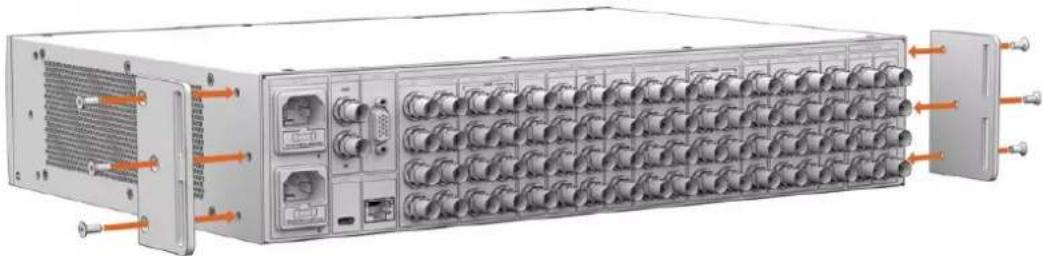
Rack Mounting
Teranex Mini Rack Shelf is a 1RU shelf that lets you install Blackmagic Ultimatte 12 HD Mini and Ultimatte 12 HD models into a broadcast rack or road case.
Blackmagic Ultimatte 12 HD Mini and Ultimatte 12 HD are small, so you can install them next to other Blackmagic Design equipment that share a similar form factor, such as Teranex Mini converters, Blackmagic MultiView 4 and Blackmagic Web Presenter. For example, installing a Blackmagic Ultimatte 12 HD Mini together with a HyperDeck Studio HD Mini means you can record your program or monitor output. This modular design lets you build your own custom video solutions that are portable and easy to use.
The Teranex Mini Rack Shelf Kit contains the following:
| 1 x Teranex Mini Rack Shelf | ||
| 1 x 1/6 rack width blanking panel Use the 1/6 blanking panel when mounting 1/2 rack width products with a 1/3 width unit or blanking panel | ||
| 2 x 1/3 rack width blanking panel Use 1/3 width blanking panels when mounting single products | ||
| Screws 8 x M3 5mm | 2 x M3 10mm Countersunk mounting screws | Flat nylon screws for 1/6 blanking panels |
To mount Ultimatte 12 HD Mini and Ultimatte 12 HD models:
1 The first step to mount any product to the Teranex Mini rack shelf is to remove the rubber feet from your device.
2 With both the rack and device upside down, line up the pre drilled holes on the rack with the threaded mounting holes on the device. This will be via two central mounting points on 1/3 width products or up to three mounting points on larger products such as HyperDeck Studio HD Plus. The location of the mounting points will depend on whether you are installing the unit on the left or right of the rack.
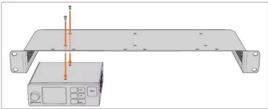
3 Using the supplied M3 5mm countersunk screws, mount the device to the rack.
Once you've installed your HyperDeck or other Blackmagic Design product, turn the rack shelf right side up and install into your equipment rack.
Blanking panels can be used to fill spaces in your rack that may be left available, such as when mounting a HyperDeck Studio HD Mini with a Blackmagic Web Presenter.
To attach the 1/6 blanking panel:
The 1/6 blanking panel is designed to be attached to 1/2 rack width products, such as HyperDeck Studio HD Plus when they are mounted solo, or with a 1/3 rack width product such as a Blackmagic Web Presenter. Mount the panel to the side of the device towards the center of the rack to allow for airflow between units.
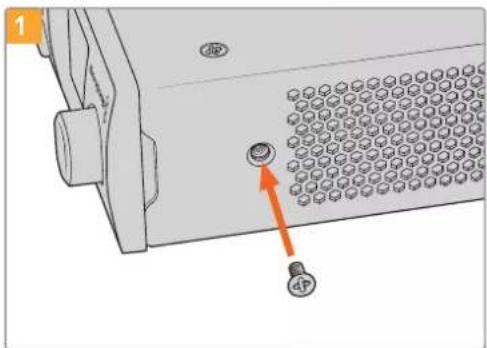
Remove the 5mm M3 screw near the front of the device.
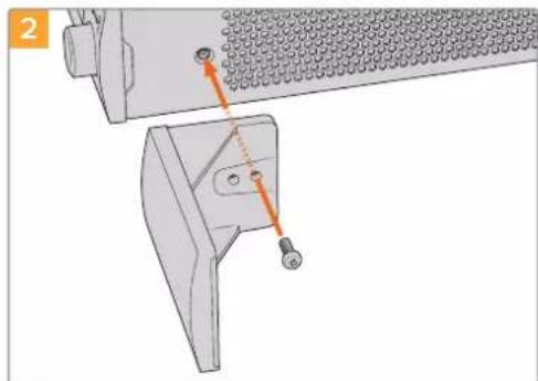
Line up the blanking panel and attach using the supplied M3 10mm nylon screw.
To attach the side 1/3 width blanking panel:
To install the 1/3 width blanking panel, line up the screw holes and anchor point with the shelf. The 1/3 width blanking panel can be used on either side or the center of the rack. Screw the panel to the shelf using two of the supplied M3 5mm countersunk screws.
For deeper products, such as the Blackmagic Studio Converter, use the Blackmagic Universal Rack Shelf.
Developer Information
Controlling Ultimatte using Telnet
The Blackmagic Ultimatte 12 Ethernet Protocol gives you the freedom to build your own custom control solutions for your Ultimatte 12. For example, you can create your own software application and control your Ultimatte via Ethernet from your computer.
The first step is to connect your Ultimatte to your computer via Ethernet. You can do this by connecting Ultimatte to the same network your computer is connected to, or you can connect Ultimatte directly to your computer.
NOTE If your Blackmagic Ultimatte is connected directly to your computer, set your computer to a manual static IP address. Set the first three blocks of numbers in the IP address to match your Ultimatte and set the subnet mask to 255.255.255.0. You can leave the gateway or router setting blank as it will not be used in a direct connection between your computer and Ultimatte.
If your network settings are set correctly, you can now open the Terminal application on Mac OS, or enable Telnet command line utilities on Windows and enter Ultimatte control protocol commands. These commands can be programmed into your application and triggered by related items on a custom user interface of your own design.
Below is a basic example of using Telnet to change the backing color, restore to factory defaults, and adjust the matte density control.
1 In the Terminal application, type the following:
telnet (IP address of main unit (space) port number)(enter)
For example: telnet 192.168.10.220 9998
Press 'enter'.
A list of status information will appear and you are ready to control your Ultimatte.
2 Now type the following:
control: (press enter)
backing color: blue (press enter twice)
Terminal will acknowledge the action with 'ack' and confirm it so you know your setting has been performed.
You have now changed Ultimatte's backing color to blue.
3 To restore to factory defaults, type the following:
control: (press enter)
factory defaults: yes (press enter twice)
This restores your Ultimatte to factory default settings and performs an automatic composite.
4 To adjust the matte density setting, type the following:
control: (press enter)
matte density: 273 (press enter twice)
Terminal will acknowledge and confirm the action.
You have now adjusted the matte density setting.
5 To exit Telnet
Hold down the control button and press the 'J' key. The Telnet prompt will appear.
Type the following:
quit press enter)
A status message will appear confirming the connection is closed.
Blackmagic Ultimatte 12 Ethernet Protocol
Version 2.0
If you are a software developer you can use Ultimatte Ethernet Protocol to construct devices that integrate with our products. Here at Blackmagic Design our approach is to open up our protocols and we eagerly look forward to seeing what you come up with!
Overview
The Blackmagic Ultimatte Ethernet Protocol is a text based protocol that is accessed by connecting to TCP port 9998 on an Ultimatte.
Ultimatte sends information in blocks. Each block has an identifying header in all caps, followed by a full colon. A block spans multiple lines and is terminated by a blank line. Each line in the protocol is terminated by a newline character.
Upon connection, the Ultimatte device sends a complete update of its status. After the initial status transmission, status updates are sent every time the Ultimatte device's status changes.
To be resilient to future protocol changes, clients should ignore blocks they do not recognize, up to the trailing blank line. Within existing blocks, clients should ignore lines that they do not recognize.
Protocol Preamble
The first block sent by Ultimatte is always the protocol preamble:
PROTOCOL PREAMBLE: Version: 2.0
The version field indicates the protocol version. When the protocol is changed in a backwards compatible way, the minor version number will be updated. If incompatible changes are made, the major version number will be updated.
Identity
The next block contains information about the device identity.
ID EN T IY:
Model: Ultimatte 12 8K
Label: Ultimatte 12 8K
Unique ID: 12345678
Network Information
There are two network blocks. The first describes the general network information and the second describes the network interface details.
NETWORK: Interface count: 1 Default Interface: 0 Static DNS Ser vers: 8.8.8.8, 8.8.4.4 Cu rrent DNS Ser vers: 8.8.8.8, 8.8.4.4
NETWORK INTERFACE 0:
Name: Cadence GigE Ethernet MAC
Priority: 0
MAC Address: xx.xx.xx.xx.xx.xx
Dynam icIP: false
Cu rre nt A d d re s s: 10.0.0.2/255.255.255.0
Cu rre nt G ate way: 10.0.0-1
Static A dd resses: 10.0.0.2/255.255.255.0
Static Gate w ay: 10.0.0.1
Version Information
The version information describes the hardware and software version numbers and identifiers of the device. For example, the "Product ID" field contains the hexadecimal USB Product Identifier.
VERSION: Product ID: BE84 Hardware Version: 0100 Software Version: 09A89B7A Software Release: 2.Q
Device Information
The next block contains general information about the connected Ultimatte device.
NOTE Some Ultimatte models will only have a subset of the above-mentioned inputs.
For example, the Ultimatte 12 HD Mini only has the following inputs:
- Foreground input (FG In), and
Background input (BG In).
Similarly, the Ultimatte 12 HD only has the following inputs:
- Foreground input (FG In),
Background input (BG In),
Garbage Matte input (GMATTE In),
Holdout Matte input (H MATTE In),
Monitor Input (MONITOR In), and
Reference Input (REF In).
Video Formats Information
The Video Formats blocks lists the video formats supported by the device. See the Video Format Control list to find the formats supported by each device.
VIDEO FORMATS: auto detect 525.59.94 NTS C 4:3 625i50 PAL 4:3 720p60 720p60
Initial Status Dump
The next eleven blocks provide the control values, control default values, current file, file list, the GPI lists, the Frame Buffer Image List and Frame Buffer State.
CONTROL:
Matte Density: 0
Red Density: 0
Green Density: 0
...(Full list in Controls section)
<sup>+</sup>
CONTROL DEFAULT LT:
Matte Density: 0
Red Density: 0
Green Density: 0
...(Full list in Controls section)
<sup>+</sup>
CUR R ENT FILE
Filename <sup>+</sup>
<sup>+</sup>
FILE LIST:
File 1
File 2
<sup>+</sup>
GPI LIST:
ID: 1
Index: 0
File 1
File 2
NOTE The Ultimatte 12 HD Mini does not have GPI inputs, so this block is not available on that device.
The IMAGE LIST block contains the filenames of images that are currently stored on the device. These images can be assigned to Frame Buffer inputs.
IM AGE LIST:
Image 1
Image 2
The FRAME BUFFER block contains the status of the Frame Buffers on the device.
This information will show:
How many image buffers are available,
- whether a frame buffer is enabled and has an image buffer assigned to it, and
- how frame buffer transitions are set up for those frame buffers that support transitions.
NOTE Frame Buffer Duration time is in milliseconds.
FRAME BUFFER: Number Of Frame Buffers: 46 BG 1 Frame Buffer Enable: off BG 1 Frame Buffer Index: 0 LY 1 Frame Buffer Enable: off LY 1 Frame Buffer Index: 0 BG 2 Frame Buffer Enable: off BG 2 Frame Buffer Index: 0 LY 2 Frame Buffer Enable: off LY 2 Frame Buffer Index: 0 GM Frame Buffer Enable: off GM Frame Buffer Index: 0 HM Frame Buffer Enable: off HM Frame Buffer Index: 0 BG Frame Buffer Mix: 0 LY Frame Buffer Mix: 0 BG Transition Duration: 0 LY Transition Duration: 0 Frame Buffer 1: Image 1 Frame Buffer 2: Image 2 ...
End Prelude
The final block of the status dump sent by Ultimatte is always end prelude:
END PRELUDE:
Status Updates
When any Control is changed on an Ultimatte device, the Ultimatte device replies with the applicable status block to all connected clients, containing only the items that have changed. For example, if Matte Density has been changed, the following block will be sent:
CONTROL: Matte Density: 0
If multiple items are changed, multiple items may be present in the update:
CONTROL: Matte Density: 0 Red Density: 0
These notifications are sent whether the change originated from the front panel, or from any other connected client.
Requesting Changes
To update a Control the client should send a block of the same form Ultimatte sends when its status changes. For example, to change Matte Density to 100, the client should send the following block:
CONTROL: Matte Density: 100
The block must be terminated by a blank line. On receipt of a blank line, Ultimatte will either acknowledge the request by responding:
ACK←
←
or indicate that the request was not understood by responding:
NAK
After a positive response, the client should expect to see a status update from Ultimatte showing the status change. This is likely to be the same as the command that was sent, but if the request could not be performed, or other changes were made simultaneously by other clients, there may be more updates in the block, or more blocks. Simultaneous updates could cancel each other out, leading to a response that is different to that expected.
In the absence of simultaneous updates, a simple control change will result in the following protocol exchange:
CONTROL:
Matte Density: 0 ACK
CONTROLC:
Matte Density: 0
The asynchronous nature of the responses means that a client should never rely on the desired update actually occurring and must simply watch for status updates from Ultimatte and use only these to update its local representation of Ultimatte's state.
A client may also request Ultimatte to change a control by a relative amount. For example, to change Matte Density by 10, the client should send the following block:
CONTROL:
Offset Matte Density: 10
Only controls with numerical ranges support this relative mode.
Requesting a Status Dump
The client may request that Ultimatte resend the complete state of any status block by sending the header of the block, followed by a blank line. In the following example, the client requests Ultimatte resend the control status:
CONTROL: ACK
CONTROL:
Matte Density: 0
Red Density: 0
Green Density: 0
... (Full list in Controls section)
File System
The client may request that Ultimatte load, save, delete, or rename a file. To load a file the client should send the following block:
FILE:
Load:
Ultimatte will respond with an ACK followed by a Current File block or a Message block.
To save, delete, or rename a file the client should send one of the following blocks:
FILE:
Save: <filename>
<
FILE:
Delete: <filename>
<
FILE:
Rename: <filename>
To: <filena me>
<
In each case Ultimatte will respond with an ACK followed by a File List block or a Message block.
GPI Event List
The client may request that Ultimatte add, insert or remove an event to a GPI Event List by sending an Insert GPI Event or Remove GPI Event command, followed by a blank line.
For example, to insert an event, the client should send the following block:
GPI:
ID: 1
Insert: <filename>
At: -1 {The insertion index. A '-1' represents the end of the list}
To remove an event a client would send the following block:
GPI:
ID: 1
Remove: 1 ← {Event index to remove. A '0' will delete all events}
To set the current event index a client would send the following block:
GPI: ID: 1 Index: 1
Ultimatte will respond with an ACK message followed by either a GPI List Block or a Message Block.
GPI LIST:
ID: 1
Index: 0
File 1
File 2
...
or
MESSAGE:
Warning: Event limit exceeded
Frame Buffer
The client may request that the Ultimatte device assign a pre-loaded image from its Media Pool into a particular frame buffer and enable/disable the frame buffer. To assign and enable an image to the BG frame buffer the following commands are required:
FRAME BUFFER:←
BG 1 Frame Buffer Index: 1 BG 1 Frame Buffer Enable: on-
To disable the frame buffer only the enable command is required:
FRAME BUFFER: BG1FrameBufferEnable:on
NOTE The Telnet interface does not currently provide loading or removing images in the Media Pool. This has to be done from either a Smart Remote 4, or using the Software Control application. Refer to the 'using the media pool' section of this manual for more information.
Camera Control
Ultimatte 12 HD Mini can be used to control an attached camera via SDI or HDMI, please refer to the 'Camera Control via Ultimatte 12 HD Mini' section for more information. For SDI Camera Control, the Ultimatte device's Camera ID may be changed using the CAMERACONTROL block:
CAMERACONTROI CameraId:1←
NOTE This control block is only available on the Ultimatte 12 HD Mini.
| Controls | |
| Matte Density 0-10000 | |
| Black Gloss 0-10000 | |
| Blue Density 0-10000 | |
| Green Density 0-10000 | |
| Red Density 0-10000 | |
| Shadow Level 0-10000 | |
| Shadow Threshold 0-10000 | |
| Matte Correct Horizontal Size 0-6 | |
| Matte Correct Vertical Size 0-3 | |
| Cursor X 0-10000 | |
| Cursor Y 0-10000 | |
| Cursor 2 X 0-10000 | |
| Cursor 2 Y 0-10000 | |
| Vell Master 0-10000 | |
| Vell Red 0-10000 | |
| Vell Green 0-10000 | |
| Vell Blue 0-10000 | |
| Vell Correct Horizontal Size | 0-6 |
| Vell Correct Vertical Size | 0-61 |
| Wall Color Red | 0-10000 |
| Wall Color Green | 0-10000 |
| Wall Color Blue | 0-10000 |
| Floor Color Red | 0-10000 |
| Floor Color Green | 0-10000 |
| Floor Color Blue | 0-10000 |
| Cleanup Level 0-10000 | |
| Cleanup Dark Recover | 0-10000 |
| Cleanup Light Recover | 0-10000 |
| Cleanup Strength | 0-10000 |
| GM Cleanup Level | 0-10000 |
| GM Cleanup Dark Recover | 0-10000 |
| GM Cleanup Light Recover | 0-10000 |
| GM Cleanup Strength | 0-10000 |
| Correction Level | 0-10000 |
| Noise Level | 0-10000 |
| Black Balance 0-10000 | |
| Gray Balance | 0-10000 |
| White Balance 0-10000 | |
| Flare Level 0-10000 | |
| Cool 0-10000 | |
| Skin Tone 0-10000 | |
| Light Warm 0-10000 | |
| Dark Warm 0-10000 | |
| Flare Correct Horizontal Size 0-6 | |
| Flare Correct Vertical Size 0-6 | 1 |
| Ambiance Master 0-10000 | |
| Ambiance Red 0-10000 | |
| Ambiance Green 0-10000 | |
| Ambiance Blue 0-10000 | |
| Ambiance Strength 0-10000 | |
| Direct Light Red | 0-10000 |
| Direct Light Green | 0-10000 |
| Direct Light Blue | 0-10000 |
| Direct Light Mix | 0-10000 |
| Vertical Blur | 0-10000 |
| FG Saturation Red | 0-10000 |
| FG Saturation Green | 0-10000 |
| FG Saturation Blue | 0-10000 |
| FG Saturation Master | 0-10000 |
| FG Contrast Red | 0-10000 |
| FG Contrast Green | 0-10000 |
| FG Contrast Blue | 0-10000 |
| FG Contrast Master | 0-10000 |
| FG Black Red | 0-10000 |
| FG Black Green | 0-10000 |
| FG Black Blue | 0-10000 |
| FG Black Master | 0-10000 |
| FG White Red | 0-10000 |
| FG White Green | 0-10000 |
| FG White Blue | 0-10000 |
| FG White Master | 0-10000 |
| FG Contrast Crossover | 0-10000 |
| Fade Mix | 0-10000 |
| BG Saturation Red | 0-10000 |
| BG Saturation Green 0-10000 | |
| BG Saturation Blue 0-10000 | |
| BG Saturation Master 0-10000 | |
| BG Contrast Red 0-10000 | |
| BG Contrast Green 0-10000 | |
| BG Contrast Blue 0-10000 | |
| BG Contrast Master 0-10000 | |
| BG Black Red 0-10000 | |
| BG Black Green 0-10000 | |
| BG Black Blue 0-10000 | |
| BG Black Master 0-10000 | |
| BG White Red 0-10000 | |
| BG White Green 0-10000 | |
| BG White Blue 0-10000 | |
| BG White Master 0-10000 | |
| BG Contrast Crossover 0-10000 | |
| BG Filter 0-10000 | |
| Test Signal Master | 0-10000 |
| Test Signal Red | 0-10000 |
| Test Signal Green | 0-10000 |
| Test Signal Blue | 0-10000 |
| LY Saturation Red | 0-10000 |
| LY Saturation Green | 0-10000 |
| LY Saturation Blue | 0-10000 |
| LY Saturation Master 0-10000 | |
| LY Contrast Red | 0-10000 |
| LY Contrast Green | 0-10000 |
| LY Contrast Blue | 0-10000 |
| LY Contrast Master 0-10000 | |
| LY Black Red | 0-10000 |
| LY Black Green | 0-10000 |
| LY Black Blue | 0-10000 |
| LY Black Master | 0-10000 |
| LY White Red | 0-10000 |
| LY White Green | 0-10000 |
| LY White Blue | 0-10000 |
| LY White Master | 0-10000 |
| LY Contrast Crossover 0-10000 | |
| LY Filter 0-10000 | |
| LY Test Signal Master 0-10000 | |
| LY Test Signal Red 0-10000 | |
| LY Test Signal Green 0-10000 | |
| LY Test Signal Blue 0-10000 | |
| LY Fade Mlx 0-10000 | |
| Lighting Level Red 0-10000 | |
| Lighting Level Green 0-10000 | |
| Lighting Level Blue 0-10000 | |
| Lighting Level Master 0-10000 | |
| Lighting Minimum Level 0-10000 | |
| Window Position Top 0-[Based on Video Format] | |
| Window Position Bottom 0-[Based on Video Format] | |
| Window Position Left 0-[Based on Video Format] | |
| Window Position Right 0-[Based on Video Format] | |
| Window Softness Top 0-10000 | |
| Window Softness Bottom | 0-10000 |
| Window Softness Left 0-10000 | |
| Window Softness Right | 0-10000 |
| Window Skew Top 0-10000 | |
| Window Skew Bottom | 0-10000 |
| Window Skew Left | 0-10000 |
| Window Skew Right | 0-10000 |
| Window Skew Offset Top | 0-10000 |
| Window Skew Offset Bottom | 0-10000 |
| Window Skew Offset Left | 0-10000 |
| Window Skew Offset Right | 0-10000 |
| Transition Rate | 1-120 |
| BM Process Horizontal | 0-3 |
| BM Process Vertical | 0-3 |
| BM Filter | 0-10000 |
| BM Input Level | 0-10000 |
| BM Input Offset | 0-10000 |
| GM Process Horizontal | 0-3 |
| GM Process Vertical | 0-3 |
| GM Filter | 0-10000 |
| GM Input Level 0-10000 | |
| GM Input Offset 0-10000 | |
| HM Process Horizontal 0-3 | |
| HM Process Vertical 0-3 | |
| HM Filter 0-10000 | |
| HM Input Level 0-10000 | |
| HM Input Offset 0-10000 | |
| LM Process Horizontal 0-3 | |
| LM Process Vertical 0-3 | |
| LM Filter 0-10000 | |
| LM Input Level 0-10000 | |
| LM Input Offset 0-10000 | |
| Noise Cursor X 0-10000 | |
| Noise Cursor Y 0-10000 | |
| FG Input Frame Delay 0-14 | |
| FG Input U Position 0-10000 | |
| FG Input V Position | 0-10000 |
| FG Input UV Position | 0-10000 |
| Talent Highlight Level** | 0-10000 |
| Monitor Highlight Level | 0-10000 |
| Matte Out Level 0-10000 | |
| Output Offset | -1500-+1500 |
| GP Out Delay* | 1-120 |
| GP1 Input Delay* | 1-120 |
| GP2 Input Delay* | 1-120 |
| GP3 Input Delay* | 1-120 |
| GP4 Input Delay* | 1-120 |
| GP5 Input Delay* | 1-120 |
| Matte Enable | On/Off |
| Screen Correct On/Off | |
| GM Cleanup Enable | On/Off |
| Noise Enable | On/Off |
| Noise Cursor Enable | On/Off |
| FG Freeze | On/Off |
| FG Advanced Contrast Enable | On/Off |
| Advanced Flare Enable | On/Off |
| HM Flare Enable | On/Off |
Controls
| Ambiance Enable On/Off | |
| BG Gradient Enable On/Off | |
| BG Freeze On/Off | |
| BG Advanced Contrast Enable On/Off | |
| BG Test Signal Enable On/Off | |
| LY Input Enable On/Off | |
| LY Advanced Contrast Enable On/Off | |
| LY Freeze** On/Off | |
| LY Test Signal Enable On/Off | |
| Lighting Enable On/Off | |
| Window Enable On/Off | |
| Window BM Enable On/Off | |
| Window GM Enable | On/Off |
| Window HM Enable | On/Off |
| Window LM Enable | On/Off |
| Window Invert | On/Off |
| Wall Cursor Position Enable | On/Off |
| Floor Cursor Position Enable | On/Off |
| Dual Cursor | On/Off |
| Manual Color Enable | On/Off |
| Custom Powerup(deprecated) | On/Off |
| BM Enable | On/Off |
| BM Invert | On/Off |
| BM Process Invert | On/Off |
| BM Freeze** | On/Off |
| GM Enable | On/Off |
| GM Invert | On/Off |
| GM Process Invert | On/Off |
| GM Freeze* | On/Off |
| HM Enable | On/Off |
| HM Invert | On/Off |
| HM Process Invert | On/Off |
| HM Freeze* | On/Off |
| LM Invert | On/Off |
| LM Process Invert | On/Off |
| Monitor To Program | On/Off |
| Monitor To Talent** | On/Off |
Controls
| Fill Linear Mix Correction* On/Off | |
| Talent Mirror** On/Off | |
| Monitor Cascade On/Off | |
| Matte Out Invert* On/Off | |
| On Air Enable On/Off | |
| On Air Lockout On/Off | |
| Matte View Range On/Off | |
| Matte View Invert On/Off | |
| Monitor Out RGB On/Off | |
| Monitor Out Red Only On/Off | |
| Monitor Out Green Only On/Off | |
| Monitor Out Blue Only On/Off | |
| GP Out Save* On/Off | |
| Quickload 1 | On/Off |
| Quickload 2 | On/Off |
| Quickload 3 | On/Off |
| Quickload 4 | On/Off |
| Quickload 5 | On/Off |
| Quicksave 1 | On/Off |
| Quicksave 2 | On/Off |
| Quicksave 3 | On/Off |
| Quicksave 4 | On/Off |
| Quicksave 5 | On/Off |
| GP 1 Input Enable* On/Off | |
| GP 2 Input Enable* | On/Off |
| GP 3 Input Enable* | On/Off |
| GP 4 Input Enable* | On/Off |
| GP 5 Input Enable* | On/Off |
| GP 1 High Enable* | On/Off |
| GP 2 High Enable* | On/Off |
| GP 3 High Enable* On/Off | |
| GP 4 High Enable* On/Off | |
| GP 5 High Enable* | On/Off |
| Tally Active | On/Off (Read Only) |
| 3G SDI level | A/B |
| Color Space* | Rec.709/Rec.2020 |
| Filter Mode | Median/Average |
| Controls | |
| Filter Median 0/1/2/3/4 | |
| Filter Average 0/1/2/3/4 | |
| LY In Mix Mode Realistic/Linear/Additive | |
| Backing Color Red/Green/Blue | |
| Cursor Position Default/Last | |
| GP Out Level" High/Low | |
| Output Range Normal/Full | 2 |
| Monitor Out Program, FG, BG, Combined | Matte, Internal Matte, Fill, Layer In, Background Matte In, Garbage Matte In, Holdout Matte In, Layer Matte In, Processed LM, Processed HM, Processed GM, Processed BM, Screen Correction |
| Layer Order FG/Layer/BG Layer/BG, Layer/FG/ | BG Layer/BG, Layer/BG Layer/FG/BG, BG Layer/Layer/FG/BG, BG Layer/FG/BG Layer/FG/ |
| Layer/BG, FG/BG Layer/Layer/BG, FG/BG Layer/BG, BG Layer/FG/BG, FG/Layer/BG, Layer/FG/BG | |
| Video Format Auto Detect, 525i59.94 NTSC 4:3, | 625i50 PAL 4:3, 720p60, 720p59.94, 720p50, 1080i60, 1080i59.94, 1080i50, 1080p60, 1080p59.94, 1080p50, 1080p30, 1080p29.97, 1080p25, 1080p24, 1080p23.98, 1080PsF30, 1080PsF29.97, 1080PsF25, 1080PsF24, 1080PsF23.98, 2160p60, 2160p59.94, 2160p50, 2160p30, 2160p29.97, 2160p25, 2160p24, 2160p23.98, 4320p60, 4320p59.94, 4320p50, 4320p30, 4320p29.97, 4320p25, 4320p24 and 4320p23.98* |
| Factory Defaults Yes | 5 |
| User Defaults Yes | 5 |
| Auto Screen Sample Yes | 5 |
| Screen Capture Yes | 5 |
| Noise Select | Yes5 |
| Sample Wall | Yes5 |
| Sample Floor | Yes5 |
| Matte Reset Yes | 5 |
| Cleanup Reset | Yes5 |
| GM Cleanup Reset | Yes5 |
| FG Color Reset | Yes5 |
| BG Color Reset Yes | 5 |
| Flare Reset | Yes5 |
| Ambiance Reset Yes | 5 |
| BG Test Signal Color Reset Yes | 5 |
| LY Color Reset Yes | 5 |
| LY Test Signal Color Reset Yes | 5 |
| Window Reset Yes | 5 |
| Window Skew Reset Yes | 5 |
| GP Out* Yes | 5 |
1 These ranges are Ultimatte device dependent. For Ultimate 12 8K running protocol 2.0, the range is 0-6. For Ultimatte 12 running version 1.2, the range is 0-3.
2 These controls are only available in protocol version 2.0 and up.
3 Loop outputs for 'garbage matte' and 'holdout matte' inputs are available for Ultimatte 12, not Ultimatte 12 8K.
4 Supported video formats are Ultimatte device dependent. 4320p formats are available for Ultimatte 12 8K. Ultimatte 12 HD Mini does not support PsF video formats.
5 These controls represent functions. Send 'Yes' to execute the function. Ultimatte will respond with a 'Yes' to indicate the function is complete.
* These controls are not available on the Ultimatte 12 HD Mini
These controls are not available of the Ultimatte 12 HD or HD Mini
| Glossary | |
| FG | Foreground |
| BG | Background |
| LY | Layer |
| GM | Garbage Matte |
| BM | Background Matte |
| HM | Holdout Matte |
| LM | Layer Matte |
Help
Getting Help
The fastest way to obtain help is to go to the Blackmagic Design online support pages and check the latest support material available for your Blackmagic Ultimatte or Smart Remote 4.
Blackmagic Design online support pages
The latest manual, software and support notes can be found at the Blackmagic Design support center at www.blackmagicdesign.com/support.
Contacting Blackmagic Design support
If you can't find the help you need in our support material, please use the 'Send us an email' button on the support page to email a support request. Alternatively, click on the 'Find your local support team' button on the support page and call your nearest Blackmagic Design support office.
Checking the version currently installed
To check which version of Blackmagic Ultimatte Setup software is installed on your computer, launch Blackmagic Ultimatte Setup and click on the 'about' tab. The software version number will be displayed in the 'software information' section.
How to get the latest updates
After checking the version of Blackmagic Ultimatte Setup software installed on your computer, please visit the Blackmagic Design support center at www.blackmagicdesign.com/support to check for the latest updates. While it is usually a good idea to run the latest updates, it is a wise practice to avoid updating any software if you are in the middle of an important project.
Regulatory Notices and Safety Information
Regulatory Notices
Disposal of waste of electrical and electronic equipment within the European union.

The symbol on the product indicates that this equipment must not be disposed of with other waste materials. In order to dispose of your waste equipment, it must be handed over to a designated collection point for recycling. The separate collection and recycling of your waste equipment at the time of disposal will help conserve natural resources and ensure that it is recycled in a manner that protects human health and the environment. For more information about where you can drop off your waste equipment for recycling, please contact your local city recycling office or the dealer from whom you purchased the product.

This equipment has been tested and found to comply with the limits for a Class A digital device, pursuant to Part 15 of the FCC rules. These limits are designed to provide reasonable protection against harmful interference when the equipment is operated in a commercial environment. This equipment generates, uses, and can radiate radio frequency energy and if not installed and used in accordance with the instructions, may cause harmful interference to radio communications. Operation of this product in a residential area is likely to cause harmful interference, in which case the user will be required to correct the interference at personal expense.
Operation is subject to the following two conditions:
1 This device may not cause harmful interference.
2 This device must accept any interference received, including interference that may cause undesired operation.

R-R-BMD-20200824001
R-R-BMD-20211110001
R-R-BMD-20211110002
R-R-BMD-20211110003
MSIP-REM-BMD-201709001
MSIP-REM-BMD-201707003
Safety Information
This equipment must be connected to a mains socket outlet with a protective earth connection.
To reduce the risk of electric shock, do not expose this equipment to dripping or splashing.
This equipment is suitable for use in tropical locations with an ambient temperature of up to 40^ .
Ensure that adequate ventilation is provided around the product and is not restricted.
When rack mounting, ensure the ventilation is not restricted by adjacent equipment.
Only use the designed threaded holes on the base, see Rack Mounting section for details.

No operator serviceable parts inside. Refer servicing to your local Blackmagic Design service centre.
Use only at altitudes not more than 2000m above sea level.
Warnings for Authorized Service Personnel

Disconnect power from both power inlets before servicing!
Caution - Double Pole/ Neutral Fusing
The power supply contained in this equipment has a fuse in both line and neutral conductors and is suitable for connection to the IT power distribution system in Norway.
Warranty
12 Month Limited Warranty
Blackmagic Design warrants that this product will be free from defects in materials and workmanship for a period of 12 months from the date of purchase. If a product proves to be defective during this warranty period, Blackmagic Design, at its option, either will repair the defective product without charge for parts and labor, or will provide a replacement in exchange for the defective product.
In order to obtain service under this warranty, you the Customer, must notify Blackmagic Design of the defect before the expiration of the warranty period and make suitable arrangements for the performance of service. The Customer shall be responsible for packaging and shipping the defective product to a designated service center nominated by Blackmagic Design, with shipping charges pre paid. Customer shall be responsible for paying all shipping charges, insurance, duties, taxes, and any other charges for products returned to us for any reason.
This warranty shall not apply to any defect, failure or damage caused by improper use or improper or inadequate maintenance and care. Blackmagic Design shall not be obligated to furnish service under this warranty: a) to repair damage resulting from attempts by personnel other than Blackmagic Design representatives to install, repair or service the product, b) to repair damage resulting from improper use or connection to incompatible equipment, c) to repair any damage or malfunction caused by the use of non Blackmagic Design parts or supplies, or d) to service a product that has been modified or integrated with other products when the effect of such a modification or integration increases the time or difficulty of servicing the product. THIS WARRANTY IS GIVEN BY BLACKMAGIC DESIGN IN LIEU OF ANY OTHER WARRANTYES, EXPRESS OR IMPLIED. BLACKMAGIC DESIGN AND ITS VENDORS DISCLAIMER ANY IMPLIED WARRANTYES OF MERCHANTABILITY OR FITNESS FOR A PARTICULAR PURPOSE. BLACKMAGIC DESIGN'S RESPONSIBILITY TO REPAIR OR REPLACE DEFECTIVE PRODUCTS IS THE WHOLE AND EXCLUSIVE REMEDY PROVIDED TO THE CUSTOMER FOR ANY INDIRECT, SPECIAL, INCIDENTAL OR CONSEQUENTIAL DAMAGES IRRESPECTIVE OF WHETHER BLACKMAGIC DESIGN OR THE VENDOR HAS ADVANCE NOTICE OF THE POSSIBILITY OF SUCH DAMAGES. BLACKMAGIC DESIGN IS NOT LIABLE FOR ANY ILLEGAL USE OF EQUIPMENT BY CUSTOMER. BLACKMAGIC IS NOT LIABLE FOR ANY DAMAGES RESULTING FROM USE OF THIS PRODUCT. USER OPERATES THIS PRODUCT AT OWN RISK.
Copyright 2022 Blackmagic Design. All rights reserved. 'Blackmagic Design', 'DockLink', 'HDLink', 'Workgroup Videohub', 'Multibridge Pro', 'Multibridge Extreme', 'Intensity' and 'Leading the creative video revolution' are registered trademarks in the US and other countries. All other company and product names may be trade marks of their respective companies with which they are associated.
Thunderbolt and the Thunderbolt logo are trademarks of Intel Corporation in the U.S. and/or other countries.
Ultimatte 12


好乙乙
This is a Blackmagic Ultimatte.
This is the most popular and most popular use of the Multi-Channel System. It is a combination of two channels, one channel for the application and the other channel for the user. The Multi-Channel System is a system that uses a single channel to carry information from one channel to another. This system is also called the Multi-Channel System.
Blackmagic Design CEO
目次
| Ultimatteに这样 | 108 | FUNCTIONS (機能) | 131 | |||||||||||||||||||||||||||||||||||||||||||||||||||||||||||||||||||||||||||||||||||||||||||||||||||||
| マットのは? | 108 | Stème-タスロー | 131 | |||||||||||||||||||||||||||||||||||||||||||||||||||||||||||||||||||||||||||||||||||||||||||||||||||||
| マットの種類 | 109 | MONITOR OUTPUT (モニーダ出力) | 132 | |||||||||||||||||||||||||||||||||||||||||||||||||||||||||||||||||||||||||||||||||||||||||||||||||||||
| はじろに | 112 | 設定コntonローチル | 132 | |||||||||||||||||||||||||||||||||||||||||||||||||||||||||||||||||||||||||||||||||||||||||||||||||||||
| 電源の接続 | 112 | MXDEIA PRIL の使 用 | 133 | |||||||||||||||||||||||||||||||||||||||||||||||||||||||||||||||||||||||||||||||||||||||||||||||||||||
| 言語の設定 | 112 | Stチルでリボーヤーキットるフィアイ ルフィーマット | 134 | |||||||||||||||||||||||||||||||||||||||||||||||||||||||||||||||||||||||||||||||||||||||||||||||||||||
| カメラ・フィアガラウンドの接続 | 113 | Stチルバックガランドおばレイヤ 一の才務広 | 134 | |||||||||||||||||||||||||||||||||||||||||||||||||||||||||||||||||||||||||||||||||||||||||||||||||||||
| スイチヤーに接続 | Ultimateの合成フーワ克莱ロ一 | 135 | ||||||||||||||||||||||||||||||||||||||||||||||||||||||||||||||||||||||||||||||||||||||||||||||||||||||
| モニタRong | 114 | 合成作成のクイックガイド | 136 | |||||||||||||||||||||||||||||||||||||||||||||||||||||||||||||||||||||||||||||||||||||||||||||||||||||
| 自動合成の設定 | 114 | フィアガラウindsの背景色の設定 | 1 | |||||||||||||||||||||||||||||||||||||||||||||||||||||||||||||||||||||||||||||||||||||||||||||||||||||
| モニタOneのカスケート接続 | 115 | 背景スケート補正の設定 | 137 | |||||||||||||||||||||||||||||||||||||||||||||||||||||||||||||||||||||||||||||||||||||||||||||||||||||
| コncyケーレー | 116 | 118 マット濃度の設定 | 138 | |||||||||||||||||||||||||||||||||||||||||||||||||||||||||||||||||||||||||||||||||||||||||||||||||||||
| 対応ビデオフィーマット | 完璧な合成を作成する | 138 | ||||||||||||||||||||||||||||||||||||||||||||||||||||||||||||||||||||||||||||||||||||||||||||||||||||||
| FTONトCONTOルバモルの使用 | 119 | Ultimateの高 度なコntonローチル | 140 | |||||||||||||||||||||||||||||||||||||||||||||||||||||||||||||||||||||||||||||||||||||||||||||||||||||
| LCDデイスリ� | 119 | 120 マットコnton口 一部の調整 | 140 | |||||||||||||||||||||||||||||||||||||||||||||||||||||||||||||||||||||||||||||||||||||||||||||||||||||
| クイックリリドロボン | StoDALEWINDのFLAEXCONTO口 | |||||||||||||||||||||||||||||||||||||||||||||||||||||||||||||||||||||||||||||||||||||||||||||||||||||||
| MXUNER (MENU) | 120 | 一方の調整 | 145 | |||||||||||||||||||||||||||||||||||||||||||||||||||||||||||||||||||||||||||||||||||||||||||||||||||||
| ロック(LOCK) | 120 | 一方の調整 | ||||||||||||||||||||||||||||||||||||||||||||||||||||||||||||||||||||||||||||||||||||||||||||||||||||||
| LCDMXUNER设定 | 120 | StoDALEWINDのANPHEENSTO | ||||||||||||||||||||||||||||||||||||||||||||||||||||||||||||||||||||||||||||||||||||||||||||||||||||||
| SETTADRAFTSETDRAFTSETDRAFTSETDRAFTSETDRAFTSETDRAFTSETDRAFTSETDRAFTSETDRAFTSETDRAFTSETDRAFTSETDRAFTSETDRAFTSETDRAFTSETDRAFTSETDRAFTSETDRAFTSETDRAFTSETDRAFTSETDRAFTSETDRAFTSETDRAFTSETDRAFTSETDRAFTSETDRAFTSETDRAFTSETDRAFTSETDRAFTSETDRAFTSETDRAFTSETDRAFTSETDRAFTSETDRAFTSETDRAFTSETDraft | 120 121 | 120 121 | 120 121 | 120 121 | 120 121 | 120 121 | 120 121 | 120 121 | 120 121 | 120 121 | 120 121 | 120 121 | 120 121 | 12 | ||||||||||||||||||||||||||||||||||||||||||||||||||||||||||||||||||||||||||||||||||||||||||
| NTTOWE イリリリリリリリリリリリリリリリリリリリリリリリリリリリリリリリリリリリリリリリリリリリリリリリリリリリリリリリリリリリリリリリリリリリリリリリリリリリリリリリリリリリリリリリリリリリリリリリリリリリリUR | 124 | レイヤーのその他の設定 | 150 | |||||||||||||||||||||||||||||||||||||||||||||||||||||||||||||||||||||||||||||||||||||||||||||||||||||
| RSETTALRESE | 124 | MATTE IN設定 | 152 | |||||||||||||||||||||||||||||||||||||||||||||||||||||||||||||||||||||||||||||||||||||||||||||||||||||
| UltimateのCONTOローツル | 125 | SETTINGS (設定) | 155 | |||||||||||||||||||||||||||||||||||||||||||||||||||||||||||||||||||||||||||||||||||||||||||||||||||||
| Ultimate Software Control | 125 | System (SIMATEM) | 155 | |||||||||||||||||||||||||||||||||||||||||||||||||||||||||||||||||||||||||||||||||||||||||||||||||||||
| Ultimate software control UnsUTWA CONTOLE CONTOLE CONTOLE CONTOLE CONTOLE CONTOLE CONTOLE CONTOLE CONTOLE CONTOLE CONTOLE CONTOLE CONTOLE CONTOLE CONTOLE CONTOLE CONTOLE CONTOLE CONTOLE CONTOLE CONTOLE CONTOLE CONTOLE CONTOLE CONTOLE CONTOLO CONTOLE CONTOLE CONTOLE CONTOLE CONTOLE CONTOLE CONTOLE CONTOLE CONTOLE CONTOLE CONTOLE CONTOLE CONTOLE CONTOLE CONTOLE CONTOLE CONTOLE CONTOLE CONTOLE CONTOLE CONTOLE CONTOLE CONTOLE CONTOLE CONTOL CONTOLE CONTOLE CONTOLE CONTOLE CONTOLE CONTOLE CONTOLE CONTOLE CONTOLE CONTOLE CONTOLE CONTOLE CONTOLE CONTOLE CONTOLE CONTOLE CONTOLE CONTOLE CONTOLE CONTOLE CONTOLE CONTOLE CONTOLE CONTOLE CONTORE CONTOLE CONTOLE CONTOLE CONTOLE CONTOLE CONTOLE CONTOLE CONTOLE CONTOLE CONTOLE CONTOLE CONTOLE CONTOLE CONTOLE CONTOLE CONTOLE CONTOLE CONTOLE CONTOLE CONTOLE CONTOLE CONTOLE CONTOLE CONTOLE CONTOILE CONTOLE CONTOLE CONTOLE CONTOLE CONTOLE CONTOLE CONTOLE CONTOLE CONTOLE CONTOLE CONTOLE CONTOLE CONTOLE CONTOLE CONTOLE CONTOLE CONTOLE CONTOLE CONTOLE CONTOLE CONTOLE CONTOLE CONTOLE CONTOLE CONTOLEY CONTOLE CONTOLE CONTOLE CONTOLE CONTOLE CONTOLE CONTOLE CONTOLE CONTOLE CONTOLE CONTOLE CONTOLE CONTOLE CONTOLE CONTOLE CONTOLE CONTOLE CONTOLE CONTOLE CONTOLE CONTOLE CONTOLE CONTOLE CONTOLE CONTOULE CONTOLE CONTOLE CONTOLE CONTOLE CONTOLE CONTOLE CONTOLE CONTOLE CONTOLE CONTOLE CONTOLE CONTOLE CONTOLE CONTOLE CONTOLE CONTOLE CONTOLE CONTOLE CONTOLE CONTOLE CONTOLE CONTOLE CONTOLE CONTOLE CONTOUE CONTOLE CONTOLE CONTOLE CONTOLE CONTOLE CONTOLE CONTOLE CONTOLE CONTOLE CONTOLE CONTOLE CONTOLE CONTOLE CONTOLE CONTOLE CONTOLE CONTOLE CONTOLE CONTOLE CONTOLE CONTOLE CONTOLE CONTOLE CONTOLE CONTOIE CONTOLE CONTOLE CONTOLE CONTOLE CONTOLE CONTOLE CONTOLE CONTOLE CONTOLE CONTOLE CONTOLE CONTOLE CONTOLE CONTOLE CONTOLE CONTOLE CONTOLE CONTOLE CONTOLE CONTOLE CONTOLE CONTOLE CONTOLE CONTOLE CONTOPE CONTOLE CONTOLE CONTOLE CONTOLE CONTOLE CONTOLE CONTOLE CONTOLE CONTOLE CONTOLE CONTOLE CONTOLE CONTOLE CONTOLE CONTOLE CONTOLE CONTOLE CONTOLE CONTOLE CONTOLE CONTOLE CONTOLE CONTOLE CONTOLE CONTOLINE CONTOLINE CONTOLINE CONTOLINE CONTOLINE CONTOLINE CONTOLINE CONTOLINE CONTOLINE CONTOLINE CONTOLINE CONTOLINE CONTOLINE CONTOLINE CONTOLINE CONTOLINE CONTOLINE CONTOLINE CONTOLINE CONTOLINE CONTOLINE CONTOLINE CONTOLINE CONTOLINE CONTOLINE CONTO LINE CONTOLINE CONTOLINE CONTOLINE CONTOLINE CONTOLINE CONTOLINE CONTOLINE CONTOLINE CONTOLINE CONTOLINE CONTOLINE CONTOLINE CONTOLINE CONTOLINE CONTOLINE CONTOLINE CONTOLINE CONTOLINE CONTOLINE CONTOLINE CONTOLINE CONTOLINE CONTOLINE CONTOLINE CONTOLine CONTOLINE CONTOLINE CONTOLINE CONTOLINE CONTOLINE CONTOLINE CONTOLINE CONTOLINE CONTOLINE CONTOLINE CONTOLINE CONTOLINE CONTOLINE CONTOLINE CONTOLINE CONTOLINE CONTOLINE CONTOLINE CONTOLINE CONTOLINE CONTOLINE CONTOLINE CONTOLINE CONTOLINE CONTOline CONTOLINE CONTOLINE CONTOLINE CONTOLINE CONTOLINE CONTOLINE CONTOLINE CONTOLINE CONTOLINE CONTOLINE CONTOLINE CONTOLINE CONTOLINE CONTOLINE CONTOLINE CONTOLINE CONTOLINE CONTOLINE CONTOLINE CONTOLINE CONTOLINE CONTOLINE CONTOLINE CONTOLINE CONTO-line CONTOLINE CONTOLINE CONTOLINE CONTOLINE CONTOLINE CONTOLINE CONTOLINE CONTOLINE CONTOLINE CONTOLINE CONTOLINE CONTOLINE CONTOLINE CONTOLINE CONTOLINE CONTOLINE CONTOLINE CONTOLINE CONTOLINE CONTOLINE CONTOLINE CONTOLINE CONTOLINE CONTOLINE CONTO线 CONTOLINE CONTOLINE CONTOLINE CONTOLINE CONTOLINE CONTOLINE CONTOLINE CONTOLINE CONTOLINE CONTOLINE CONTOLINE CONTOLINE CONTOLINE CONTOLINE CONTOLINE CONTOLINE CONTOLINE CONTOLINE CONTOLINE CONTOLINE CONTOLINE CONTOLINE CONTOLINE CONTOLINE CONTOL CONTOLINE CONTOLINE CONTOLINE CONTOLINE CONTOLINE CONTOLINE CONTOLINE CONTOLINE CONTOLINE CONTOLINE CONTOLINE CONTOLINE CONTOLINE CONTOLINE CONTOLINE CONTOLINE CONTOLINE CONTOLINE CONTOLINE CONTOLINE CONTOLINE CONTOLINE CONTOLINE CONTOLINE CONTO line CONTOLINE CONTOLINE CONTOLINE CONTOLINE CONTOLINE CONTOLINE CONTOLINE CONTOLINE CONTOLINE CONTOLINE CONTOLINE CONTOLINE CONTOLINE CONTOLINE CONTOLINE CONTOLINE CONTOLINE CONTOLINE CONTOLINE CONTOLINE CONTOLINE CONTOLINE CONTOLINE CONTOLINE CONTOLTE CONTOLINE CONTOLINE CONTOLINE CONTOLINE CONTOLINE CONTOLINE CONTOLINE CONTOLINE CONTOLINE CONTOLINE CONTOLINE CONTOLINE CONTOLINE CONTOLINE CONTOLINE CONTOLINE CONTOLINE CONTOLINE CONTOLINE CONTOLINE CONTOLINE CONTOLINE CONTOLINE CONTOLINE CONTONL CONTOLINE CONTOLINE CONTOLINE CONTOLINE CONTOLINE CONTOLINE CONTOLINE CONTOLINE CONTOLINE CONTOLINE CONTOLINE CONTOLINE CONTOLINE CONTOLINE CONTOLINE CONTOLINE CONTOLINE CONTOLINE CONTOLINE CONTOLINE CONTOLINE CONTOLINE CONTOLINE CONTOLINE CONTO線 CONTOLINE CONTOLINE CONTOLINE CONTOLINE CONTOLINE CONTOLINE CONTOLINE CONTOLINE CONTOLINE CONTOLINE CONTOLINE CONTOLINE CONTOLINE CONTOLINE CONTOLINE CONTOLINE CONTOLINE CONTOLINE CONTOLINE CONTOLINE CONTOLINE CONTOLINE CONTOLINE CONTOLINE CONTO号线 CONTOLINE CONTOLINE CONTOLINE CONTOLINE CONTOLINE CONTOLINE CONTOLINE CONTOLINE CONTOLINE CONTOLINE CONTOLINE CONTOLINE CONTOLINE CONTOLINE CONTOLINE CONTOLINE CONTOLINE CONTOLINE CONTOLINE CONTOLINE CONTOLINE CONTOLINE CONTOLINE CONTOLINE CONTODATE CONTOLINE CONTOLINE CONTOLINE CONTOLINE CONTOLINE CONTOLINE CONTOLINE CONTOLINE CONTOLINE CONTOLINE CONTOLINE CONTOLINE CONTOLINE CONTOLINE CONTOLINE CONTOLINE CONTOLINE CONTOLINE CONTOLINE CONTOLINE CONTOLINE CONTOLINE CONTOLINE CONTOLINE CONTO在线 | 114 | 114 | 114 | 114 | 114 | 114 | 114 | 114 | 114 | |||||||||||||||||||||||||||||||||||||||||||||||||||||||||||||||||||||||||||||||||||||||||||||||
| 114 | 114 | 114 | 114 | 114 | 114 | 114 | 114 | 114 | 114 | |||||||||||||||||||||||||||||||||||||||||||||||||||||||||||||||||||||||||||||||||||||||||||||||
| 114 | 114 | 114 | 114 | 114 | 114 | 114 | 114 | 114 | 114 | |||||||||||||||||||||||||||||||||||||||||||||||||||||||||||||||||||||||||||||||||||||||||||||||
| 114 | 114 | 114 | 114 | 115 | 115 | 115 | 115 | 115 | 115 | |||||||||||||||||||||||||||||||||||||||||||||||||||||||||||||||||||||||||||||||||||||||||||||||
| 114 | 115 | 115 | 115 | 115 | 115 | 115 | 115 | 115 | 115 | |||||||||||||||||||||||||||||||||||||||||||||||||||||||||||||||||||||||||||||||||||||||||||||||
| 114 | 115 | 115 | 115 | 115 | 115 | 115 | 115 | 115 | 115 | |||||||||||||||||||||||||||||||||||||||||||||||||||||||||||||||||||||||||||||||||||||||||||||||
| 114 | 115 | 115 | 115 | 115 | 115 | 115 | 116 | 116 | 116 | |||||||||||||||||||||||||||||||||||||||||||||||||||||||||||||||||||||||||||||||||||||||||||||||
| 114 | 115 | 115 | 115 | 115 | 115 | 115 | 116 | 116 | 116 | |||||||||||||||||||||||||||||||||||||||||||||||||||||||||||||||||||||||||||||||||||||||||||||||
| 114 | 115 | 115 | 115 | 115 | 115 | 115 | 116 | 116 | 116 | |||||||||||||||||||||||||||||||||||||||||||||||||||||||||||||||||||||||||||||||||||||||||||||||
| 114 | 115 | 115 | 115 | 115 | 115 | 116 | 116 | 116 | ||||||||||||||||||||||||||||||||||||||||||||||||||||||||||||||||||||||||||||||||||||||||||||||||
| 114 | 115 | 115 | 115 | 115 | 115 | 115 | 116 | 116 | 116 | |||||||||||||||||||||||||||||||||||||||||||||||||||||||||||||||||||||||||||||||||||||||||||||||
| 114 | 115 | 115 | 115 | 115 | 115 | 115 | 115 | 116 | 116 | |||||||||||||||||||||||||||||||||||||||||||||||||||||||||||||||||||||||||||||||||||||||||||||||
| 114 | 115 | 115 | 115 | 115 | 115 | 115 | 116 | 116 | 116 | |||||||||||||||||||||||||||||||||||||||||||||||||||||||||||||||||||||||||||||||||||||||||||||||
| 114 | 115 | 115 | 115 | 115 | 115 | 115 | 116 | 116 | 116 | |||||||||||||||||||||||||||||||||||||||||||||||||||||||||||||||||||||||||||||||||||||||||||||||
| 114 | 115 | 115 | 115 | 115 | 115 | 116 | 116 | 116 | ||||||||||||||||||||||||||||||||||||||||||||||||||||||||||||||||||||||||||||||||||||||||||||||||
| 114 | 115 | 115 | 115 | 115 | 115 | 116 | 116 | 116 | ||||||||||||||||||||||||||||||||||||||||||||||||||||||||||||||||||||||||||||||||||||||||||||||||
| 114 | 115 | 115 | 115 | 115 | 115 | 116 | 116 | |||||||||||||||||||||||||||||||||||||||||||||||||||||||||||||||||||||||||||||||||||||||||||||||||
| 114 | 115 | 115 | 115 | 115 | 115 | 116 | 116 | |||||||||||||||||||||||||||||||||||||||||||||||||||||||||||||||||||||||||||||||||||||||||||||||||
| 114 | 115 | 115 | 115 | 115 | 115 | 116 | 116 | |||||||||||||||||||||||||||||||||||||||||||||||||||||||||||||||||||||||||||||||||||||||||||||||||
| 114 | 115 | 115 | 115 115 | 115 | 115 | |||||||||||||||||||||||||||||||||||||||||||||||||||||||||||||||||||||||||||||||||||||||||||||||||||
| 114 | 115 | 115 | 115 | 115 | 115 | |||||||||||||||||||||||||||||||||||||||||||||||||||||||||||||||||||||||||||||||||||||||||||||||||||
| 114 | 115 | 115 | 115 | 115 | 115 | |||||||||||||||||||||||||||||||||||||||||||||||||||||||||||||||||||||||||||||||||||||||||||||||||||
| 114 | 115 | 115 | 115 | 115 | 115 | |||||||||||||||||||||||||||||||||||||||||||||||||||||||||||||||||||||||||||||||||||||||||||||||||||
| 114 | 115 | 115 | 115 | 115 | 100 |
163
164
165
一九166
一力伊的作成 166
一九伊の復元 167
M二一の力斯 168
Ultimatte 12 HD Miniを介uting
力x拉口 一169
不th7-ck接 171
IPアドレスの設定 171
Red/Green/Blue Density (Ledd/Grill-1/2/3-1)
Dual Sampling (duAralsAnP
照明条件或gul-100k之,壁的部比比较上,床的部分的绿为异的辉度色合以见。是。此也了场合、丁力卜的自动sunprnge未是Mua尔的singrsant 15.342679800000000000000000000000000000000000000000000000000
Noise Reduction/Generation (N1X除去/生成)
Black/Gray/White Balance (Strauss/Gele- /Hofiusbuns)
FIOAGLWINDoT-ON 領域(SHD、MDD、八IAI卜等)以的SbIL 抑制の力一 而调整。
Flare Level (FleAleBé)
Direct Light Red/Green/Blue (直接照明Lett/Drill/Brill/
Black Level Master (brackle)
75 10000000000000000000000000000000000000000000000000000000000000000000000000000000000000000000000000000
Lighting Level Red/Green/Blue (照明レル赤/緑/青)
LY In Additive (L'Y-入力加算)
This boton is a Web site for the company. The site has been created to provide information about the company's products and services. The site also includes information about the company's customer service, technical information, and financial information.
Inputs (入力)
GPI High Enable (GPI八有功)
GPI In Delay (GPI入力遲延)
This is the best way to use the basic operation of the computer. The computer can be used in a variety of applications, such as for example in the classroom, at home, at work, at school, at school and at home.
The Blackmagic Ultimatte 12 Ethernet Protocol gives you the freedom to build your own custom control solutions for your Ultimatte 12. For example, you can create your own software application and control your Ultimatte via Ethernet from your computer.
The first step is to connect your Ultimatte to your computer via Ethernet. You can do this by connecting Ultimatte to the same network your computer is connected to, or you can connect Ultimatte directly to your computer.
NOTE If your Blackmagic Ultimatte is connected directly to your computer, set your computer to a manual static IP address. Set the first three blocks of numbers in the IP address to match your Ultimatte and set the subnet mask to 255.255.255.0. You can leave the gateway or router setting blank as it will not be used in a direct connection between your computer and Ultimatte.
If your network settings are set correctly, you can now open the Terminal application on Mac OS, or enable Telnet command line utilities on Windows and enter Ultimatte control protocol commands. These commands can be programmed into your application and triggered by related items on a custom user interface of your own design.
Below is a basic example of using Telnet to change the backing color, restore to factory defaults, and adjust the matte density control.
1 In the Terminal application, type the following:
telnet (IP address of main unit (space) port number)(enter)
For example: telnet 192.168.10.220 9998
Press 'enter'.
A list of status information will appear and you are ready to control your Ultimatte.
2 Now type the following:
control: (press enter)
backing color: blue (press enter twice)
Terminal will acknowledge the action with 'ack' and confirm it so you know your setting has been performed.
You have now changed Ultimatte's backing color to blue.
3 To restore to factory defaults, type the following:
control: (press enter)
factory defaults: yes (press enter twice)
This restores your Ultimatte to factory default settings and performs an automatic composite.
4 To adjust the matte density setting, type the following:
control: (press enter)
matte density: 273 (press enter twice)
Terminal will acknowledge and confirm the action.
You have now adjusted the matte density setting.
5 To exit Telnet
Hold down the control button and press the 'J' key. The Telnet prompt will appear.
Type the following:
quit press enter)
A status message will appear confirming the connection is closed.
Blackmagic Ultimatte 12 Ethernet Protocol
Version 2.0
If you are a software developer you can use Ultimatte Ethernet Protocol to construct devices that integrate with our products. Here at Blackmagic Design our approach is to open up our protocols and we eagerly look forward to seeing what you come up with!
Overview
The Blackmagic Ultimatte Ethernet Protocol is a text based protocol that is accessed by connecting to TCP port 9998 on an Ultimatte.
Ultimatte sends information in blocks. Each block has an identifying header in all caps, followed by a full colon. A block spans multiple lines and is terminated by a blank line. Each line in the protocol is terminated by a newline character.
Upon connection, the Ultimatte device sends a complete update of its status. After the initial status transmission, status updates are sent every time the Ultimatte device's status changes.
To be resilient to future protocol changes, clients should ignore blocks they do not recognize, up to the trailing blank line. Within existing blocks, clients should ignore lines that they do not recognize.
Protocol Preamble
The first block sent by Ultimatte is always the protocol preamble:
PROTOCOL PREAMBLE: Version: 2.0
The version field indicates the protocol version. When the protocol is changed in a backwards compatible way, the minor version number will be updated. If incompatible changes are made, the major version number will be updated.
Identity
The next block contains information about the device identity.
ID EN T IY:
Model: Ultimatte 12 8K
Label: Ultimatte 12 8K
Unique ID: 12345678
Network Information
There are two network blocks. The first describes the general network information and the second describes the network interface details.
NETWORK: Interface count: 1 Default Interface: 0 Static DNS Ser vers: 8.8.8.8, 8.8.4.4 Cu rrent DNS Ser vers: 8.8.8.8, 8.8.4.4
NETWORK INTERFACE 0:
Name: Cadence GigE Ethernet MAC
Priority: 0
MAC Address: xx.xx.xx.xx.xx.xx
Dynam icIP: false
Cu rre nt A d d re s s: 10.0.0.2/255.255.255.0
Cu rre nt G ate way: 10.0.0-1
Static A dd resses: 10.0.0.2/255.255.255.0
Static Gate w ay: 10.0.0.1
Version Information
The version information describes the hardware and software version numbers and identifiers of the device. For example, the "Product ID" field contains the hexadecimal USB Product Identifier.
VERSION: Product ID: BE84 Hardware Version: 0100 Software Version: 09A89B7A Software Release: 2.Q
Device Information
The next block contains general information about the connected Ultimatte device.
NOTE Some Ultimatte models will only have a subset of the above-mentioned inputs.
For example, the Ultimatte 12 HD Mini only has the following inputs:
- Foreground input (FG In), and
Background input (BG In).
Similarly, the Ultimatte 12 HD only has the following inputs:
- Foreground input (FG In),
Background input (BG In),
Garbage Matte input (GMATTE In),
Holdout Matte input (H MATTE In),
Monitor Input (MONITOR In), and
Reference Input (REF In).
Video Formats Information
The Video Formats blocks lists the video formats supported by the device. See the Video Format Control list to find the formats supported by each device.
VIDEO FORMATS: auto detect 525.59.94 NTS C 4:3 625i50 PAL 4:3 720p60 720p60
Initial Status Dump
The next eleven blocks provide the control values, control default values, current file, file list, the GPI lists, the Frame Buffer Image List and Frame Buffer State.
CONTROL:
Matte Density: 0
Red Density: 0
Green Density: 0
...(Full list in Controls section)
<sup>+</sup>
CONTROL DEFAULT LT:
Matte Density: 0
Red Density: 0
Green Density: 0
...(Full list in Controls section)
<sup>+</sup>
CUR R ENT FILE
Filename <sup>+</sup>
<sup>+</sup>
FILE LIST:
File 1
File 2
<sup>+</sup>
GPI LIST:
ID: 1
Index: 0
File 1
File 2
NOTE The Ultimatte 12 HD Mini does not have GPI inputs, so this block is not available on that device.
The IMAGE LIST block contains the filenames of images that are currently stored on the device. These images can be assigned to Frame Buffer inputs.
IM AGE LIST:
Image 1
Image 2
The FRAME BUFFER block contains the status of the Frame Buffers on the device.
This information will show:
How many image buffers are available,
- whether a frame buffer is enabled and has an image buffer assigned to it, and
- how frame buffer transitions are set up for those frame buffers that support transitions.
NOTE Frame Buffer Duration time is in milliseconds.
FRAME BUFFER: Number Of Frame Buffers: 46 BG 1 Frame Buffer Enable: off BG 1 Frame Buffer Index: 0 LY 1 Frame Buffer Enable: off LY 1 Frame Buffer Index: 0 BG 2 Frame Buffer Enable: off BG 2 Frame Buffer Index: 0 LY 2 Frame Buffer Enable: off LY 2 Frame Buffer Index: 0 GM Frame Buffer Enable: off GM Frame Buffer Index: 0 HM Frame Buffer Enable: off HM Frame Buffer Index: 0 BG Frame Buffer Mix: 0 LY Frame Buffer Mix: 0 BG Transition Duration: 0 LY Transition Duration: 0 Frame Buffer 1: Image 1 Frame Buffer 2: Image 2 ...
End Prelude
The final block of the status dump sent by Ultimatte is always end prelude:
END PRELUDE:
Status Updates
When any Control is changed on an Ultimatte device, the Ultimatte device replies with the applicable status block to all connected clients, containing only the items that have changed. For example, if Matte Density has been changed, the following block will be sent:
CONTROL: Matte Density: 0
If multiple items are changed, multiple items may be present in the update:
CONTROL: Matte Density: 0 Red Density: 0
These notifications are sent whether the change originated from the front panel, or from any other connected client.
Requesting Changes
To update a Control the client should send a block of the same form Ultimatte sends when its status changes. For example, to change Matte Density to 100, the client should send the following block:
CONTROL: Matte Density: 100
The block must be terminated by a blank line. On receipt of a blank line, Ultimatte will either acknowledge the request by responding:
ACK←
←
or indicate that the request was not understood by responding:
NAK
After a positive response, the client should expect to see a status update from Ultimatte showing the status change. This is likely to be the same as the command that was sent, but if the request could not be performed, or other changes were made simultaneously by other clients, there may be more updates in the block, or more blocks. Simultaneous updates could cancel each other out, leading to a response that is different to that expected.
In the absence of simultaneous updates, a simple control change will result in the following protocol exchange:
CONTROL:
Matte Density: 0 ACK
CONTROLC:
Matte Density: 0
The asynchronous nature of the responses means that a client should never rely on the desired update actually occurring and must simply watch for status updates from Ultimatte and use only these to update its local representation of Ultimatte's state.
A client may also request Ultimatte to change a control by a relative amount. For example, to change Matte Density by 10, the client should send the following block:
CONTROL:
Offset Matte Density: 10
Only controls with numerical ranges support this relative mode.
Requesting a Status Dump
The client may request that Ultimatte resend the complete state of any status block by sending the header of the block, followed by a blank line. In the following example, the client requests Ultimatte resend the control status:
CONTROL: ACK
CONTROL:
Matte Density: 0
Red Density: 0
Green Density: 0
... (Full list in Controls section)
File System
The client may request that Ultimatte load, save, delete, or rename a file. To load a file the client should send the following block:
FILE:
Load:
Ultimatte will respond with an ACK followed by a Current File block or a Message block.
To save, delete, or rename a file the client should send one of the following blocks:
FILE:
Save: <filename>
<
FILE:
Delete: <filename>
<
FILE:
Rename: <filename>
To: <filena me>
<
In each case Ultimatte will respond with an ACK followed by a File List block or a Message block.
GPI Event List
The client may request that Ultimatte add, insert or remove an event to a GPI Event List by sending an Insert GPI Event or Remove GPI Event command, followed by a blank line.
For example, to insert an event, the client should send the following block:
GPI:
ID: 1
Insert: <filename>
At: -1 {The insertion index. A '-1' represents the end of the list}
To remove an event a client would send the following block:
GPI:
ID: 1
Remove: 1 ← {Event index to remove. A '0' will delete all events}
To set the current event index a client would send the following block:
GPI: ID: 1 Index: 1
Ultimatte will respond with an ACK message followed by either a GPI List Block or a Message Block.
GPI LIST:
ID: 1
Index: 0
File 1
File 2
...
or
MESSAGE:
Warning: Event limit exceeded
Frame Buffer
The client may request that the Ultimatte device assign a pre-loaded image from its Media Pool into a particular frame buffer and enable/disable the frame buffer. To assign and enable an image to the BG frame buffer the following commands are required:
FRAME BUFFER:←
BG 1 Frame Buffer Index: 1 BG 1 Frame Buffer Enable: on-
To disable the frame buffer only the enable command is required:
FRAME BUFFER: BG1FrameBufferEnable:on
NOTE The Telnet interface does not currently provide loading or removing images in the Media Pool. This has to be done from either a Smart Remote 4, or using the Software Control application. Refer to the 'using the media pool' section of this manual for more information.
Camera Control
Ultimatte 12 HD Mini can be used to control an attached camera via SDI or HDMI, please refer to the 'Camera Control via Ultimatte 12 HD Mini' section for more information. For SDI Camera Control, the Ultimatte device's Camera ID may be changed using the CAMERACONTROL block:
CAMERACONTROI CameraId:1
NOTE This control block is only available on the Ultimatte 12 HD Mini.
| Controls | |
| Matte Density 0-10000 | |
| Black Gloss 0-10000 | |
| Blue Density 0-10000 | |
| Green Density 0-10000 | |
| Red Density 0-10000 | |
| Shadow Level 0-10000 | |
| Shadow Threshold 0-10000 | |
| Matte Correct Horizontal Size 0-6 | |
| Matte Correct Vertical Size 0-3 | |
| Cursor X 0-10000 | |
| Cursor Y 0-10000 | |
| Cursor 2 X 0-10000 | |
| Cursor 2 Y 0-10000 | |
| Vell Master 0-10000 | |
| Vell Red 0-10000 | |
| Vell Green 0-10000 | |
| Vell Blue 0-10000 | |
| Vell Correct Horizontal Size | 0-6 |
| Vell Correct Vertical Size | 0-61 |
| Wall Color Red | 0-10000 |
| Wall Color Green | 0-10000 |
| Wall Color Blue | 0-10000 |
| Floor Color Red | 0-10000 |
| Floor Color Green | 0-10000 |
| Floor Color Blue | 0-10000 |
| Cleanup Level 0-10000 | |
| Cleanup Dark Recover | 0-10000 |
| Cleanup Light Recover | 0-10000 |
| Cleanup Strength | 0-10000 |
| GM Cleanup Level | 0-10000 |
| GM Cleanup Dark Recover | 0-10000 |
| GM Cleanup Light Recover | 0-10000 |
| GM Cleanup Strength | 0-10000 |
| Correction Level | 0-10000 |
| Noise Level | 0-10000 |
| Black Balance 0-10000 | |
| Gray Balance | 0-10000 |
Controls
| White Balance 0-10000 | |
| Flare Level 0-10000 | |
| Cool 0-10000 | |
| Skin Tone 0-10000 | |
| Light Warm 0-10000 | |
| Dark Warm 0-10000 | |
| Flare Correct Horizontal Size 0-6 | |
| Flare Correct Vertical Size 0-6 | 1 |
| Ambiance Master 0-10000 | |
| Ambiance Red 0-10000 | |
| Ambiance Green 0-10000 | |
| Ambiance Blue 0-10000 | |
| Ambiance Strength 0-10000 | |
| Direct Light Red | 0-10000 |
| Direct Light Green | 0-10000 |
| Direct Light Blue | 0-10000 |
| Direct Light Mix | 0-10000 |
| Vertical Blur | 0-10000 |
| FG Saturation Red | 0-10000 |
| FG Saturation Green | 0-10000 |
| FG Saturation Blue | 0-10000 |
| FG Saturation Master | 0-10000 |
| FG Contrast Red | 0-10000 |
| FG Contrast Green | 0-10000 |
| FG Contrast Blue | 0-10000 |
| FG Contrast Master | 0-10000 |
| FG Black Red | 0-10000 |
| FG Black Green | 0-10000 |
| FG Black Blue | 0-10000 |
| FG Black Master | 0-10000 |
| FG White Red | 0-10000 |
| FG White Green | 0-10000 |
| FG White Blue | 0-10000 |
| FG White Master | 0-10000 |
| FG Contrast Crossover | 0-10000 |
| Fade Mix | 0-10000 |
| BG Saturation Red | 0-10000 |
| Controls | |
| BG Saturation Green 0-10000 | |
| BG Saturation Blue 0-10000 | |
| BG Saturation Master 0-10000 | |
| BG Contrast Red 0-10000 | |
| BG Contrast Green 0-10000 | |
| BG Contrast Blue 0-10000 | |
| BG Contrast Master 0-10000 | |
| BG Black Red 0-10000 | |
| BG Black Green 0-10000 | |
| BG Black Blue 0-10000 | |
| BG Black Master 0-10000 | |
| BG White Red 0-10000 | |
| BG White Green 0-10000 | |
| BG White Blue 0-10000 | |
| BG White Master 0-10000 | |
| BG Contrast Crossover 0-10000 | |
| BG Filter 0-10000 | |
| Test Signal Master | 0-10000 |
| Test Signal Red | 0-10000 |
| Test Signal Green | 0-10000 |
| Test Signal Blue | 0-10000 |
| LY Saturation Red | 0-10000 |
| LY Saturation Green | 0-10000 |
| LY Saturation Blue | 0-10000 |
| LY Saturation Master 0-10000 | |
| LY Contrast Red | 0-10000 |
| LY Contrast Green | 0-10000 |
| LY Contrast Blue | 0-10000 |
| LY Contrast Master 0-10000 | |
| LY Black Red | 0-10000 |
| LY Black Green | 0-10000 |
| LY Black Blue | 0-10000 |
| LY Black Master | 0-10000 |
| LY White Red | 0-10000 |
| LY White Green | 0-10000 |
| LY White Blue | 0-10000 |
| LY White Master | 0-10000 |
| LY Contrast Crossover 0-10000 | |
| LY Filter 0-10000 | |
| LY Test Signal Master 0-10000 | |
| LY Test Signal Red 0-10000 | |
| LY Test Signal Green 0-10000 | |
| LY Test Signal Blue 0-10000 | |
| LY Fade Mlx 0-10000 | |
| Lighting Level Red 0-10000 | |
| Lighting Level Green 0-10000 | |
| Lighting Level Blue 0-10000 | |
| Lighting Level Master 0-10000 | |
| Lighting Minimum Level 0-10000 | |
| Window Position Top 0-[Based on Video Format] | |
| Window Position Bottom 0-[Based on Video Format] | |
| Window Position Left 0-[Based on Video Format] | |
| Window Position Right 0-[Based on Video Format] | |
| Window Softness Top 0-10000 | |
| Window Softness Bottom | 0-10000 |
| Window Softness Left 0-10000 | |
| Window Softness Right | 0-10000 |
| Window Skew Top 0-10000 | |
| Window Skew Bottom | 0-10000 |
| Window Skew Left | 0-10000 |
| Window Skew Right | 0-10000 |
| Window Skew Offset Top | 0-10000 |
| Window Skew Offset Bottom | 0-10000 |
| Window Skew Offset Left | 0-10000 |
| Window Skew Offset Right | 0-10000 |
| Transition Rate | 1-120 |
| BM Process Horizontal | 0-3 |
| BM Process Vertical | 0-3 |
| BM Filter | 0-10000 |
| BM Input Level | 0-10000 |
| BM Input Offset | 0-10000 |
| GM Process Horizontal | 0-3 |
| GM Process Vertical | 0-3 |
| GM Filter | 0-10000 |
| GM Input Level 0-10000 | |
| GM Input Offset 0-10000 | |
| HM Process Horizontal 0-3 | |
| HM Process Vertical 0-3 | |
| HM Filter 0-10000 | |
| HM Input Level 0-10000 | |
| HM Input Offset 0-10000 | |
| LM Process Horizontal 0-3 | |
| LM Process Vertical 0-3 | |
| LM Filter 0-10000 | |
| LM Input Level 0-10000 | |
| LM Input Offset 0-10000 | |
| Noise Cursor X 0-10000 | |
| Noise Cursor Y 0-10000 | |
| FG Input Frame Delay 0-14 | |
| FG Input U Position 0-10000 | |
| FG Input V Position | 0-10000 |
| FG Input UV Position | 0-10000 |
| Talent Highlight Level** | 0-10000 |
| Monitor Highlight Level | 0-10000 |
| Matte Out Level 0-10000 | |
| Output Offset | -1500-+1500 |
| GP Out Delay* | 1-120 |
| GP1 Input Delay* | 1-120 |
| GP2 Input Delay* | 1-120 |
| GP3 Input Delay* | 1-120 |
| GP4 Input Delay* | 1-120 |
| GP5 Input Delay* | 1-120 |
| Matte Enable | On/Off |
| Screen Correct On/Off | |
| GM Cleanup Enable | On/Off |
| Noise Enable | On/Off |
| Noise Cursor Enable | On/Off |
| FG Freeze | On/Off |
| FG Advanced Contrast Enable | On/Off |
| Advanced Flare Enable | On/Off |
| HM Flare Enable | On/Off |
Controls
| Ambiance Enable On/Off | |
| BG Gradient Enable On/Off | |
| BG Freeze On/Off | |
| BG Advanced Contrast Enable On/Off | |
| BG Test Signal Enable On/Off | |
| LY Input Enable On/Off | |
| LY Advanced Contrast Enable On/Off | |
| LY Freeze** On/Off | |
| LY Test Signal Enable On/Off | |
| Lighting Enable On/Off | |
| Window Enable On/Off | |
| Window BM Enable On/Off | |
| Window GM Enable | On/Off |
| Window HM Enable | On/Off |
| Window LM Enable | On/Off |
| Window Invert | On/Off |
| Wall Cursor Position Enable | On/Off |
| Floor Cursor Position Enable | On/Off |
| Dual Cursor | On/Off |
| Manual Color Enable | On/Off |
| Custom Powerup(deprecated) | On/Off |
| BM Enable | On/Off |
| BM Invert | On/Off |
| BM Process Invert | On/Off |
| BM Freeze** | On/Off |
| GM Enable | On/Off |
| GM Invert | On/Off |
| GM Process Invert | On/Off |
| GM Freeze* | On/Off |
| HM Enable | On/Off |
| HM Invert | On/Off |
| HM Process Invert | On/Off |
| HM Freeze* | On/Off |
| LM Invert | On/Off |
| LM Process Invert | On/Off |
| Monitor To Program | On/Off |
| Monitor To Talent** | On/Off |
| Controls | |
| Fill Linear Mix Correction* On/Off | |
| Talent Mirror** On/Off | |
| Monitor Cascade On/Off | |
| Matte Out Invert* On/Off | |
| On Air Enable On/Off | |
| On Air Lockout On/Off | |
| Matte View Range On/Off | |
| Matte View Invert On/Off | |
| Monitor Out RGB On/Off | |
| Monitor Out Red Only On/Off | |
| Monitor Out Green Only On/Off | |
| Monitor Out Blue Only On/Off | |
| GP Out Save* On/Off | |
| Quickload 1 | On/Off |
| Quickload 2 | On/Off |
| Quickload 3 | On/Off |
| Quickload 4 | On/Off |
| Quickload 5 | On/Off |
| Quicksave 1 | On/Off |
| Quicksave 2 | On/Off |
| Quicksave 3 | On/Off |
| Quicksave 4 | On/Off |
| Quicksave 5 | On/Off |
| GP1 Input Enable* On/Off | |
| GP2 Input Enable* | On/Off |
| GP3 Input Enable* | On/Off |
| GP4 Input Enable* | On/Off |
| GP5 Input Enable* | On/Off |
| GP1 High Enable* | On/Off |
| GP2 High Enable* | On/Off |
| GP3 High Enable* On/Off | |
| GP4 High Enable* On/Off | |
| GP5 High Enable* | On/Off |
| Tally Active | On/Off [Read Only] |
| 3G SDI level | A/B |
| Color Space* | Rec.709/Rec.2020 |
| Filter Mode | Median/Average |
| Filter Median 0/1/2/3/4 | |
| Filter Average 0/1/2/3/4 | |
| LY In Mix Mode Realistic/Linear/Additive | |
| Backing Color Red/Green/Blue | |
| Cursor Position Default/Last | |
| GP Out Level" High/Low | |
| Output Range Normal/Full | 2 |
| Monitor Out Program, FG, BG, Combined | Matte, Internal Matte, Fill, Layer In, Background Matte In, Garbage Matte In, Holdout Matte In, Layer Matte In, Processed LM, Processed HM, Processed GM, Processed BM, Screen Correction |
| Layer Order FG/Layer/BG Layer/BG, Layer/FG/ | BG Layer/BG, Layer/BG Layer/FG/BG, BG Layer/Layer/FG/BG, BG Layer/FG/ |
| Layer/BG, FG/BG Layer/Layer/BG, FG/BG Layer/BG, BG Layer/FG/BG, FG/Layer/BG, Layer/FG/BG | |
| Video Format Auto Detect, 525i59.94 NTSC 4:3, | 625i50 PAL 4:3, 720p60, 720p59.94, 720p50, 1080i60, 1080i59.94, 1080i50, 1080p60, 1080p59.94, 1080p50, 1080p30, 1080p29.97, 1080p25, 1080p24, 1080p23.98, 1080PsF30, 1080PsF29.97, 1080PsF25, 1080PsF24, 1080PsF23.98, 2160p60, 2160p59.94, 2160p50, 2160p30, 2160p29.97, 2160p25, 2160p24, 2160p23.98, 4320p60, 4320p59.94, 4320p50, 4320p30, 4320p29.97, 4320p25, 4320p24 and 4320p23.984 |
| Factory Defaults Yes | 5 |
| User Defaults Yes | 5 |
| Auto Screen Sample Yes | 5 |
| Screen Capture Yes | 5 |
| Noise Select | Yes5 |
| Sample Wall | Yes5 |
| Sample Floor | Yes5 |
| Matte Reset Yes | 5 |
| Cleanup Reset | Yes5 |
| GM Cleanup Reset | Yes5 |
| FG Color Reset | Yes5 |
| BG Color Reset Yes | 5 |
| Flare Reset | Yes5 |
Controls
| Ambiance Reset Yes | 5 |
| BG Test Signal Color Reset Yes | 5 |
| LY Color Reset Yes | 5 |
| LY Test Signal Color Reset Yes | 5 |
| Window Reset Yes | 5 |
| Window Skew Reset Yes | 5 |
| GP Out* Yes | 5 |
1 These ranges are Ultimatte device dependent. For Ultimate 12 8K running protocol 2.0, the range is 0-6. For Ultimatte 12 running version 1.2, the range is 0-3.
2 These controls are only available in protocol version 2.0 and up.
3 Loop outputs for 'garbage matte' and 'holdout matte' inputs are available for Ultimatte 12, not Ultimatte 12 8K.
4 Supported video formats are Ultimatte device dependent. 4320p formats are available for Ultimatte 12 8K. Ultimatte 12 HD Mini does not support PsF video formats.
5 These controls represent functions. Send 'Yes' to execute the function. Ultimatte will respond with a 'Yes' to indicate the function is complete.
* These controls are not available on the Ultimatte 12 HD Mini
These controls are not available of the Ultimatte 12 HD or HD Mini
Glossary
| FG | Foreground |
| BG | Background |
| LY | Layer |
| GM | Garbage Matte |
| BM | Background Matte |
| HM | Holdout Matte |
| LM | Layer Matte |
ハルフ
ルフロー
Chere cliente, cher client,
Section Functions 233
Barred'etat 233
Section Monitor output 234
Section Monitor output
Matte Process/Screen Correction
Ambiance Level Red, Green, Blue
Ambiance Level Master
Direct Light Red, Green, Blue
Lighting Level - Red/Green/Blue
Lighting Level - Master
LY Input Realistic/Linear/Additive
Window Skew Top, Bottom, Left, Right
Frame Delay FG Input
FG Input UV Position
| Standard | Inputs |
| PGM Out | BG In |
| FG In | Layer In |
| BG In | BG Matte In |
| Combined Matte | Garbage Matte In |
| Internal Matte | Holdout Matte In |
| Fill Out | Layer Matte In |
2 Dans Ionglet Options, touchez le bouton Exit to Desktop.
The Blackmagic Ultimatte 12 Ethernet Protocol gives you the freedom to build your own custom control solutions for your Ultimatte 12. For example, you can create your own software application and control your Ultimatte via Ethernet from your computer.
The first step is to connect your Ultimatte to your computer via Ethernet. You can do this by connecting Ultimatte to the same network your computer is connected to, or you can connect Ultimatte directly to your computer.
NOTE If your Blackmagic Ultimatte is connected directly to your computer, set your computer to a manual static IP address. Set the first three blocks of numbers in the IP address to match your Ultimatte and set the subnet mask to 255.255.255.0. You can leave the gateway or router setting blank as it will not be used in a direct connection between your computer and Ultimatte.
If your network settings are set correctly, you can now open the Terminal application on Mac OS, or enable Telnet command line utilities on Windows and enter Ultimatte control protocol commands. These commands can be programmed into your application and triggered by related items on a custom user interface of your own design.
Below is a basic example of using Telnet to change the backing color, restore to factory defaults, and adjust the matte density control.
1 In the Terminal application, type the following:
telnet (IP address of main unit (space) port number)(enter)
For example: telnet 192.168.10.220 9998
Press 'enter'.
A list of status information will appear and you are ready to control your Ultimatte.
2 Now type the following:
control: (press enter)
backing color: blue (press enter twice)
Terminal will acknowledge the action with 'ack' and confirm it so you know your setting has been performed.
You have now changed Ultimatte's backing color to blue.
3 To restore to factory defaults, type the following:
control: (press enter)
factory defaults: yes (press enter twice)
This restores your Ultimatte to factory default settings and performs an automatic composite.
4 To adjust the matte density setting, type the following:
control: (press enter)
matte density: 273 (press enter twice)
Terminal will acknowledge and confirm the action.
You have now adjusted the matte density setting.
5 To exit Telnet
Hold down the control button and press the 'J' key. The Telnet prompt will appear.
Type the following:
quit press enter)
A status message will appear confirming the connection is closed.
Blackmagic Ultimatte 12 Ethernet Protocol
Version 2.0
If you are a software developer you can use Ultimatte Ethernet Protocol to construct devices that integrate with our products. Here at Blackmagic Design our approach is to open up our protocols and we eagerly look forward to seeing what you come up with!
Overview
The Blackmagic Ultimatte Ethernet Protocol is a text based protocol that is accessed by connecting to TCP port 9998 on an Ultimatte.
Ultimatte sends information in blocks. Each block has an identifying header in all caps, followed by a full colon. A block spans multiple lines and is terminated by a blank line. Each line in the protocol is terminated by a newline character.
Upon connection, the Ultimatte device sends a complete update of its status. After the initial status transmission, status updates are sent every time the Ultimatte device's status changes.
To be resilient to future protocol changes, clients should ignore blocks they do not recognize, up to the trailing blank line. Within existing blocks, clients should ignore lines that they do not recognize.
Protocol Preamble
The first block sent by Ultimatte is always the protocol preamble:
PROTOCOL PREAMBLE: Version: 2.0
The version field indicates the protocol version. When the protocol is changed in a backwards compatible way, the minor version number will be updated. If incompatible changes are made, the major version number will be updated.
Identity
The next block contains information about the device identity.
ID EN T IY:
Model: Ultimatte 12 8K
Label: Ultimatte 12 8K
Unique ID: 12345678
Network Information
There are two network blocks. The first describes the general network information and the second describes the network interface details.
NETWORK: Interface count: 1 Default Interface: 0 Static DNS Ser vers: 8.8.8.8, 8.8.4.4 Cu rrent DNS Ser vers: 8.8.8.8, 8.8.4.4
NETWORK INTERFACE 0:
Name: Cadence GigE Ethernet MAC
Priority: 0
MAC Address: xx.xx.xx.xx.xx.xx
Dynam icIP: false
Cu rre nt A d d re s e s: 10.0.0.2/255.255.255.0
Cu rre nt G ate way: 10.0.0←1
Static A dd resses: 10.0.0.2/255.255.255.0
Static Gate w ay: 10.0.0.1←1
Version Information
The version information describes the hardware and software version numbers and identifiers of the device. For example, the "Product ID" field contains the hexadecimal USB Product Identifier.
VERSION: Product ID: BE84 Hardware Version: 0100 Software Version: 09A89B7 Software Release: 2.0
Device Information
The next block contains general information about the connected Ultimatte device.
NOTE Some Ultimatte models will only have a subset of the above-mentioned inputs.
For example, the Ultimatte 12 HD Mini only has the following inputs:
- Foreground input (FG In), and
Background input (BG In).
Similarly, the Ultimatte 12 HD only has the following inputs:
- Foreground input (FG In),
Background input (BG In),
Garbage Matte input (G MATTE In),
Holdout Matte input (H MATTE In),
Monitor Input (MONITOR In), and
Reference Input (REF In).
Video Formats Information
The Video Formats blocks lists the video formats supported by the device. See the Video Format Control list to find the formats supported by each device.
VIDEO FORMATS: auto detect 525.59.94 NTS C 4:3 625i50 PAL 4:3 720p60 720p60
Initial Status Dump
The next eleven blocks provide the control values, control default values, current file, file list, the GPI lists, the Frame Buffer Image List and Frame Buffer State.
CONTROL:
Matte Density: 0
Red Density: 0
Green Density: 0
...(Full list in Controls section)
<sup>+</sup>
CONTROL DEFAULT LT:
Matte Density: 0
Red Density: 0
Green Density: 0
...(Full list in Controls section)
<sup>+</sup>
CUR R ENT FILE
Filename <sup>+</sup>
<sup>+</sup>
FILE LIST:
File 1
File 2
<sup>+</sup>
GPI LIST:
ID: 1
Index: 0
File 1
File 2
NOTE The Ultimatte 12 HD Mini does not have GPI inputs, so this block is not available on that device.
The IMAGE LIST block contains the filenames of images that are currently stored on the device. These images can be assigned to Frame Buffer inputs.
IM AGE LIST:
Image 1
Image 2
The FRAME BUFFER block contains the status of the Frame Buffers on the device.
This information will show:
How many image buffers are available,
- whether a frame buffer is enabled and has an image buffer assigned to it, and
- how frame buffer transitions are set up for those frame buffers that support transitions.
NOTE Frame Buffer Duration time is in milliseconds.
FRAME BUFFER: Number Of Frame Buffers: 46 BG 1 Frame Buffer Enable: off BG 1 Frame Buffer Index: 0 LY 1 Frame Buffer Enable: off LY 1 Frame Buffer Index: 0 BG 2 Frame Buffer Enable: off BG 2 Frame Buffer Index: 0 LY 2 Frame Buffer Enable: off LY 2 Frame Buffer Index: 0 GM Frame Buffer Enable: off GM Frame Buffer Index: 0 HM Frame Buffer Enable: off HM Frame Buffer Index: 0 BG Frame Buffer Mix: 0 LY Frame Buffer Mix: 0 BG Transition Duration: 0 LY Transition Duration: 0 Frame Buffer 1: Image 1 Frame Buffer 2: Image 2 ...
End Prelude
The final block of the status dump sent by Ultimatte is always end prelude:
END PRELUDE:
Status Updates
When any Control is changed on an Ultimatte device, the Ultimatte device replies with the applicable status block to all connected clients, containing only the items that have changed. For example, if Matte Density has been changed, the following block will be sent:
CONTROL: Matte Density: 0
If multiple items are changed, multiple items may be present in the update:
CONTROL: Matte Density: 0 Red Density: 0
These notifications are sent whether the change originated from the front panel, or from any other connected client.
Requesting Changes
To update a Control the client should send a block of the same form Ultimatte sends when its status changes. For example, to change Matte Density to 100, the client should send the following block:
CONTROL: Matte Density: 100
The block must be terminated by a blank line. On receipt of a blank line, Ultimatte will either acknowledge the request by responding:
ACK←
←
or indicate that the request was not understood by responding:
NAK
After a positive response, the client should expect to see a status update from Ultimatte showing the status change. This is likely to be the same as the command that was sent, but if the request could not be performed, or other changes were made simultaneously by other clients, there may be more updates in the block, or more blocks. Simultaneous updates could cancel each other out, leading to a response that is different to that expected.
In the absence of simultaneous updates, a simple control change will result in the following protocol exchange:
CONTROL:
Matte Density: 0 ACK
CONTROLC:
Matte Density: 0
The asynchronous nature of the responses means that a client should never rely on the desired update actually occurring and must simply watch for status updates from Ultimatte and use only these to update its local representation of Ultimatte's state.
A client may also request Ultimatte to change a control by a relative amount. For example, to change Matte Density by 10, the client should send the following block:
CONTROL:
Offset Matte Density: 10
Only controls with numerical ranges support this relative mode.
Requesting a Status Dump
The client may request that Ultimatte resend the complete state of any status block by sending the header of the block, followed by a blank line. In the following example, the client requests Ultimatte resend the control status:
CONTROL: ACK
CONTROL:
Matte Density: 0
Red Density: 0
Green Density: 0
... (Full list in Controls section)
File System
The client may request that Ultimatte load, save, delete, or rename a file. To load a file the client should send the following block:
FILE:
Load:
Ultimatte will respond with an ACK followed by a Current File block or a Message block.
To save, delete, or rename a file the client should send one of the following blocks:
FILE:
Save: <filename>
<
FILE:
Delete: <filename>
<
FILE:
Rename: <filename>
To: <filena me>
<
In each case Ultimatte will respond with an ACK followed by a File List block or a Message block.
GPI Event List
The client may request that Ultimatte add, insert or remove an event to a GPI Event List by sending an Insert GPI Event or Remove GPI Event command, followed by a blank line.
For example, to insert an event, the client should send the following block:
GPI:
ID: 1
Insert: <filename>
At: -1 {The insertion index. A '-1' represents the end of the list}
To remove an event a client would send the following block:
GPI: ID: 1 Remove: 1 {Event index to remove. A '0' will delete all events}
To set the current event index a client would send the following block:
GPI: ID: 1 Index: 1
Ultimatte will respond with an ACK message followed by either a GPI List Block or a Message Block.
GPI LIST:
ID: 1
Index: 0
File 1
File 2
...
or
MESSAGE:
Warning: Event limit exceeded
Frame Buffer
The client may request that the Ultimatte device assign a pre-loaded image from its Media Pool into a particular frame buffer and enable/disable the frame buffer. To assign and enable an image to the BG frame buffer the following commands are required:
FRAME BUFFER:←
BG 1 Frame Buffer Index: 1 BG 1 Frame Buffer Enable: on-
To disable the frame buffer only the enable command is required:
FRAME BUFFER: BG1FrameBufferEnable:on
NOTE The Telnet interface does not currently provide loading or removing images in the Media Pool. This has to be done from either a Smart Remote 4, or using the Software Control application. Refer to the 'using the media pool' section of this manual for more information.
Camera Control
Ultimatte 12 HD Mini can be used to control an attached camera via SDI or HDMI, please refer to the 'Camera Control via Ultimatte 12 HD Mini' section for more information. For SDI Camera Control, the Ultimatte device's Camera ID may be changed using the CAMERACONTROL block:
CAMERACONTROI CameraId:1←
NOTE This control block is only available on the Ultimatte 12 HD Mini.
Controls
| Matte Density 0-10000 | |
| Black Gloss 0-10000 | |
| Blue Density 0-10000 | |
| Green Density 0-10000 | |
| Red Density 0-10000 | |
| Shadow Level 0-10000 | |
| Shadow Threshold 0-10000 | |
| Matte Correct Horizontal Size 0-6 | |
| Matte Correct Vertical Size 0-3 | |
| Cursor X 0-10000 | |
| Cursor Y 0-10000 | |
| Cursor 2 X 0-10000 | |
| Cursor 2 Y 0-10000 | |
| Vell Master 0-10000 | |
| Vell Red 0-10000 | |
| Vell Green 0-10000 | |
| Vell Blue 0-10000 | |
| Vell Correct Horizontal Size | 0-6 |
| Vell Correct Vertical Size | 0-6 |
| Wall Color Red | 0-10000 |
| Wall Color Green | 0-10000 |
| Wall Color Blue | 0-10000 |
| Floor Color Red | 0-10000 |
| Floor Color Green | 0-10000 |
| Floor Color Blue | 0-10000 |
| Cleanup Level 0-10000 | |
| Cleanup Dark Recover | 0-10000 |
| Cleanup Light Recover | 0-10000 |
| Cleanup Strength | 0-10000 |
| GM Cleanup Level | 0-10000 |
| GM Cleanup Dark Recover | 0-10000 |
| GM Cleanup Light Recover | 0-10000 |
| GM Cleanup Strength | 0-10000 |
| Correction Level | 0-10000 |
| Noise Level | 0-10000 |
| Black Balance 0-10000 | |
| Gray Balance | 0-10000 |
Controls
| White Balance 0-10000 | |
| Flare Level 0-10000 | |
| Cool 0-10000 | |
| Skin Tone 0-10000 | |
| Light Warm 0-10000 | |
| Dark Warm 0-10000 | |
| Flare Correct Horizontal Size 0-6 | |
| Flare Correct Vertical Size 0-6 | 1 |
| Ambiance Master 0-10000 | |
| Ambiance Red 0-10000 | |
| Ambiance Green 0-10000 | |
| Ambiance Blue 0-10000 | |
| Ambiance Strength 0-10000 | |
| Direct Light Red | 0-10000 |
| Direct Light Green | 0-10000 |
| Direct Light Blue | 0-10000 |
| Direct Light Mix | 0-10000 |
| Vertical Blur | 0-10000 |
| FG Saturation Red | 0-10000 |
| FG Saturation Green | 0-10000 |
| FG Saturation Blue | 0-10000 |
| FG Saturation Master | 0-10000 |
| FG Contrast Red | 0-10000 |
| FG Contrast Green | 0-10000 |
| FG Contrast Blue | 0-10000 |
| FG Contrast Master | 0-10000 |
| FG Black Red | 0-10000 |
| FG Black Green | 0-10000 |
| FG Black Blue | 0-10000 |
| FG Black Master | 0-10000 |
| FG White Red | 0-10000 |
| FG White Green | 0-10000 |
| FG White Blue | 0-10000 |
| FG White Master | 0-10000 |
| FG Contrast Crossover | 0-10000 |
| Fade Mix | 0-10000 |
| BG Saturation Red | 0-10000 |
| Controls | |
| BG Saturation Green 0-10000 | |
| BG Saturation Blue 0-10000 | |
| BG Saturation Master 0-10000 | |
| BG Contrast Red 0-10000 | |
| BG Contrast Green 0-10000 | |
| BG Contrast Blue 0-10000 | |
| BG Contrast Master 0-10000 | |
| BG Black Red 0-10000 | |
| BG Black Green 0-10000 | |
| BG Black Blue 0-10000 | |
| BG Black Master 0-10000 | |
| BG White Red 0-10000 | |
| BG White Green 0-10000 | |
| BG White Blue 0-10000 | |
| BG White Master 0-10000 | |
| BG Contrast Crossover 0-10000 | |
| BG Filter 0-10000 | |
| Test Signal Master | 0-10000 |
| Test Signal Red | 0-10000 |
| Test Signal Green | 0-10000 |
| Test Signal Blue | 0-10000 |
| LY Saturation Red | 0-10000 |
| LY Saturation Green | 0-10000 |
| LY Saturation Blue | 0-10000 |
| LY Saturation Master 0-10000 | |
| LY Contrast Red | 0-10000 |
| LY Contrast Green | 0-10000 |
| LY Contrast Blue | 0-10000 |
| LY Contrast Master 0-10000 | |
| LY Black Red | 0-10000 |
| LY Black Green | 0-10000 |
| LY Black Blue | 0-10000 |
| LY Black Master | 0-10000 |
| LY White Red | 0-10000 |
| LY White Green | 0-10000 |
| LY White Blue | 0-10000 |
| LY White Master | 0-10000 |
| LY Contrast Crossover 0-10000 | |
| LY Filter 0-10000 | |
| LY Test Signal Master 0-10000 | |
| LY Test Signal Red 0-10000 | |
| LY Test Signal Green 0-10000 | |
| LY Test Signal Blue 0-10000 | |
| LY Fade Mlx 0-10000 | |
| Lighting Level Red 0-10000 | |
| Lighting Level Green 0-10000 | |
| Lighting Level Blue 0-10000 | |
| Lighting Level Master 0-10000 | |
| Lighting Minimum Level 0-10000 | |
| Window Position Top 0-[Based on Video Format] | |
| Window Position Bottom 0-[Based on Video Format] | |
| Window Position Left 0-[Based on Video Format] | |
| Window Position Right 0-[Based on Video Format] | |
| Window Softness Top 0-10000 | |
| Window Softness Bottom | 0-10000 |
| Window Softness Left 0-10000 | |
| Window Softness Right | 0-10000 |
| Window Skew Top 0-10000 | |
| Window Skew Bottom | 0-10000 |
| Window Skew Left | 0-10000 |
| Window Skew Right | 0-10000 |
| Window Skew Offset Top | 0-10000 |
| Window Skew Offset Bottom | 0-10000 |
| Window Skew Offset Left | 0-10000 |
| Window Skew Offset Right | 0-10000 |
| Transition Rate | 1-120 |
| BM Process Horizontal | 0-3 |
| BM Process Vertical | 0-3 |
| BM Filter | 0-10000 |
| BM Input Level | 0-10000 |
| BM Input Offset | 0-10000 |
| GM Process Horizontal | 0-3 |
| GM Process Vertical | 0-3 |
| GM Filter | 0-10000 |
| GM Input Level 0-10000 | |
| GM Input Offset 0-10000 | |
| HM Process Horizontal 0-3 | |
| HM Process Vertical 0-3 | |
| HM Filter 0-10000 | |
| HM Input Level 0-10000 | |
| HM Input Offset 0-10000 | |
| LM Process Horizontal 0-3 | |
| LM Process Vertical 0-3 | |
| LM Filter 0-10000 | |
| LM Input Level 0-10000 | |
| LM Input Offset 0-10000 | |
| Noise Cursor X 0-10000 | |
| Noise Cursor Y 0-10000 | |
| FG Input Frame Delay 0-14 | |
| FG Input U Position 0-10000 | |
| FG Input V Position | 0-10000 |
| FG Input UV Position | 0-10000 |
| Talent Highlight Level** | 0-10000 |
| Monitor Highlight Level | 0-10000 |
| Matte Out Level 0-10000 | |
| Output Offset | -1500-+1500 |
| GP Out Delay* | 1-120 |
| GP1 Input Delay* | 1-120 |
| GP2 Input Delay* | 1-120 |
| GP3 Input Delay* | 1-120 |
| GP4 Input Delay* | 1-120 |
| GP5 Input Delay* | 1-120 |
| Matte Enable | On/Off |
| Screen Correct On/Off | |
| GM Cleanup Enable | On/Off |
| Noise Enable | On/Off |
| Noise Cursor Enable | On/Off |
| FG Freeze | On/Off |
| FG Advanced Contrast Enable | On/Off |
| Advanced Flare Enable | On/Off |
| HM Flare Enable | On/Off |
Controls
| Ambiance Enable On/Off | |
| BG Gradient Enable On/Off | |
| BG Freeze On/Off | |
| BG Advanced Contrast Enable On/Off | |
| BG Test Signal Enable On/Off | |
| LY Input Enable On/Off | |
| LY Advanced Contrast Enable On/Off | |
| LY Freeze** On/Off | |
| LY Test Signal Enable On/Off | |
| Lighting Enable On/Off | |
| Window Enable On/Off | |
| Window BM Enable On/Off | |
| Window GM Enable | On/Off |
| Window HM Enable | On/Off |
| Window LM Enable | On/Off |
| Window Invert | On/Off |
| Wall Cursor Position Enable | On/Off |
| Floor Cursor Position Enable | On/Off |
| Dual Cursor | On/Off |
| Manual Color Enable | On/Off |
| Custom Powerup(deprecated) | On/Off |
| BM Enable | On/Off |
| BM Invert | On/Off |
| BM Process Invert | On/Off |
| BM Freeze** | On/Off |
| GM Enable | On/Off |
| GM Invert | On/Off |
| GM Process Invert | On/Off |
| GM Freeze* | On/Off |
| HM Enable | On/Off |
| HM Invert | On/Off |
| HM Process Invert | On/Off |
| HM Freeze* | On/Off |
| LM Invert | On/Off |
| LM Process Invert | On/Off |
| Monitor To Program | On/Off |
| Monitor To Talent** | On/Off |
Controls
| Fill Linear Mix Correction* On/Off | |
| Talent Mirror** On/Off | |
| Monitor Cascade On/Off | |
| Matte Out Invert* On/Off | |
| On Air Enable On/Off | |
| On Air Lockout On/Off | |
| Matte View Range On/Off | |
| Matte View Invert On/Off | |
| Monitor Out RGB On/Off | |
| Monitor Out Red Only On/Off | |
| Monitor Out Green Only On/Off | |
| Monitor Out Blue Only On/Off | |
| GP Out Save* On/Off | |
| Quickload 1 | On/Off |
| Quickload 2 | On/Off |
| Quickload 3 | On/Off |
| Quickload 4 | On/Off |
| Quickload 5 | On/Off |
| Quicksave 1 | On/Off |
| Quicksave 2 | On/Off |
| Quicksave 3 | On/Off |
| Quicksave 4 | On/Off |
| Quicksave 5 | On/Off |
| GP 1 Input Enable* On/Off | |
| GP 2 Input Enable* | On/Off |
| GP 3 Input Enable* | On/Off |
| GP 4 Input Enable* | On/Off |
| GP 5 Input Enable* | On/Off |
| GP 1 High Enable* | On/Off |
| GP 2 High Enable* | On/Off |
| GP 3 High Enable* On/Off | |
| GP 4 High Enable* On/Off | |
| GP 5 High Enable* | On/Off |
| Tally Active | On/Off (Read Only) |
| 3G SDI level | A/B |
| Color Space* | Rec.709/Rec.2020 |
| Filter Mode | Median/Average |
| Controls | |
| Filter Median 0/1/2/3/4 | |
| Filter Average 0/1/2/3/4 | |
| LY In Mix Mode Realistic/Linear/Additive | |
| Backing Color Red/Green/Blue | |
| Cursor Position Default/Last | |
| GP Out Level" High/Low | |
| Output Range Normal/Full | 2 |
| Monitor Out Program, FG, BG, Combined | Matte, Internal Matte, Fill, Layer In, Background Matte In, Garbage Matte In, Holdout Matte In, Layer Matte In, Processed LM, Processed HM, Processed GM, Processed BM, Screen Correction |
| Layer Order FG/Layer/BG Layer/BG, Layer/FG/ | BG Layer/BG, Layer/BG Layer/FG/BG, BG Layer/Layer/FG/BG, BG Layer/FG/ |
| Layer/BG, FG/BG Layer/Layer/BG, FG/BG Layer/BG, BG Layer/FG/BG, FG/Layer/BG, Layer/FG/BG | |
| Video Format Auto Detect, 525i59.94 NTSC 4:3, | 625i50 PAL 4:3, 720p60, 720p59.94, 720p50, 1080i60, 1080i59.94, 1080i50, 1080p60, 1080p59.94, 1080p50, 1080p30, 1080p29.97, 1080p25, 1080p24, 1080p23.98, 1080PsF30, 1080PsF29.97, 1080PsF25, 1080PsF24, 1080PsF23.98, 2160p60, 2160p59.94, 2160p50, 2160p30, 2160p29.97, 2160p25, 2160p24, 2160p23.98, 4320p60, 4320p59.94, 4320p50, 4320p30, 4320p29.97, 4320p25, 4320p24 and 4320p23.984 |
| Factory Defaults Yes | 5 |
| User Defaults Yes | 5 |
| Auto Screen Sample Yes | 5 |
| Screen Capture Yes | 5 |
| Noise Select | Yes5 |
| Sample Wall | Yes5 |
| Sample Floor | Yes5 |
| Matte Reset Yes | 5 |
| Cleanup Reset | Yes5 |
| GM Cleanup Reset | Yes5 |
| FG Color Reset | Yes5 |
| BG Color Reset Yes | 5 |
| Flare Reset | Yes5 |
| Ambiance Reset Yes | 5 |
| BG Test Signal Color Reset Yes | 5 |
| LY Color Reset Yes | 5 |
| LY Test Signal Color Reset Yes | 5 |
| Window Reset Yes | 5 |
| Window Skew Reset Yes | 5 |
| GP Out* Yes | 5 |
1 These ranges are Ultimatte device dependent. For Ultimate 12 8K running protocol 2.0, the range is 0-6. For Ultimatte 12 running version 1.2, the range is 0-3.
2 These controls are only available in protocol version 2.0 and up.
3 Loop outputs for 'garbage matte' and 'holdout matte' inputs are available for Ultimatte 12, not Ultimatte 12 8K.
4 Supported video formats are Ultimatte device dependent. 4320p formats are available for Ultimatte 12 8K. Ultimatte 12 HD Mini does not support PsF video formats.
5 These controls represent functions. Send 'Yes' to execute the function. Ultimatte will respond with a 'Yes' to indicate the function is complete.
* These controls are not available on the Ultimatte 12 HD Mini
These controls are not available of the Ultimatte 12 HD or HD Mini
| Glossary | |
| FG | Foreground |
| BG | Background |
| LY | Layer |
| GM | Garbage Matte |
| BM | Background Matte |
| HM | Holdout Matte |
| LM | Layer Matte |
Aide
Obtenir de l'aide
CEO Blackmagic Design
Inhaltsverzeichnis
The Blackmagic Ultimatte 12 Ethernet Protocol gives you the freedom to build your own custom control solutions for your Ultimatte 12. For example, you can create your own software application and control your Ultimatte via Ethernet from your computer.
The first step is to connect your Ultimatte to your computer via Ethernet. You can do this by connecting Ultimatte to the same network your computer is connected to, or you can connect Ultimatte directly to your computer.
NOTE If your Blackmagic Ultimatte is connected directly to your computer, set your computer to a manual static IP address. Set the first three blocks of numbers in the IP address to match your Ultimatte and set the subnet mask to 255.255.255.0. You can leave the gateway or router setting blank as it will not be used in a direct connection between your computer and Ultimatte.
If your network settings are set correctly, you can now open the Terminal application on Mac OS, or enable Telnet command line utilities on Windows and enter Ultimatte control protocol commands. These commands can be programmed into your application and triggered by related items on a custom user interface of your own design.
Below is a basic example of using Telnet to change the backing color, restore to factory defaults, and adjust the matte density control.
1 In the Terminal application, type the following:
telnet (IP address of main unit (space) port number)(enter)
For example: telnet 192.168.10.220 9998
Press 'enter'.
A list of status information will appear and you are ready to control your Ultimatte.
2 Now type the following:
control: (press enter)
backing color: blue (press enter twice)
Terminal will acknowledge the action with 'ack' and confirm it so you know your setting has been performed.
You have now changed Ultimatte's backing color to blue.
3 To restore to factory defaults, type the following:
control: (press enter)
factory defaults: yes (press enter twice)
This restores your Ultimatte to factory default settings and performs an automatic composite.
4 To adjust the matte density setting, type the following:
control: (press enter)
matte density: 273 (press enter twice)
Terminal will acknowledge and confirm the action.
You have now adjusted the matte density setting.
5 To exit Telnet
Hold down the control button and press the 'J' key. The Telnet prompt will appear.
Type the following:
quit press enter)
A status message will appear confirming the connection is closed.
Blackmagic Ultimatte 12 Ethernet Protocol
Version 2.0
If you are a software developer you can use Ultimatte Ethernet Protocol to construct devices that integrate with our products. Here at Blackmagic Design our approach is to open up our protocols and we eagerly look forward to seeing what you come up with!
Overview
The Blackmagic Ultimatte Ethernet Protocol is a text based protocol that is accessed by connecting to TCP port 9998 on an Ultimatte.
Ultimatte sends information in blocks. Each block has an identifying header in all caps, followed by a full colon. A block spans multiple lines and is terminated by a blank line. Each line in the protocol is terminated by a newline character.
Upon connection, the Ultimatte device sends a complete update of its status. After the initial status transmission, status updates are sent every time the Ultimatte device's status changes.
To be resilient to future protocol changes, clients should ignore blocks they do not recognize, up to the trailing blank line. Within existing blocks, clients should ignore lines that they do not recognize.
Protocol Preamble
The first block sent by Ultimatte is always the protocol preamble:
PROTOCOL PREAMBLE: Version: 2.0
The version field indicates the protocol version. When the protocol is changed in a backwards compatible way, the minor version number will be updated. If incompatible changes are made, the major version number will be updated.
Identity
The next block contains information about the device identity.
ID EN T IY:
Model: Ultimatte 12 8K
Label: Ultimatte 12 8K
Unique ID: 12345678
Network Information
There are two network blocks. The first describes the general network information and the second describes the network interface details.
NETWORK: Interface count: 1 Default Interface: 0 Static DNS Ser vers: 8.8.8.8, 8.8.4.4 Cu rrent DNS Ser vers: 8.8.8.8, 8.8.4.4
NETWORK INTERFACE 0:
Name: Cadence GigE Ethernet MAC
Priority: 0
MAC Address: xx.xx.xx.xx.xx.xx
Dynam icIP: false
Cu rre nt A d d re s e s: 10.0.0.2/255.255.255.0
Cu rre nt G ate way: 10.0.0←1
Static A dd resses: 10.0.0.2/255.255.255.0
Static Gate w ay: 10.0.0.1←1
Version Information
The version information describes the hardware and software version numbers and identifiers of the device. For example, the "Product ID" field contains the hexadecimal USB Product Identifier.
VERSION: Product ID: BE84 Hardware Version: 0100 Software Version: 09A89B7 Software Release: 2.0
Device Information
The next block contains general information about the connected Ultimatte device.
NOTE Some Ultimatte models will only have a subset of the above-mentioned inputs.
For example, the Ultimatte 12 HD Mini only has the following inputs:
- Foreground input (FG In), and
Background input (BG In).
Similarly, the Ultimatte 12 HD only has the following inputs:
- Foreground input (FG In),
Background input (BG In),
Garbage Matte input (G MATTE In),
Holdout Matte input (H MATTE In),
Monitor Input (MONITOR In), and
Reference Input (REF In).
Video Formats Information
The Video Formats blocks lists the video formats supported by the device. See the Video Format Control list to find the formats supported by each device.
VIDEO FORMATS: auto detect 525.59.94 NTS C 4:3625i50 PAL 4:3720p60
…
Initial Status Dump
The next eleven blocks provide the control values, control default values, current file, file list, the GPI lists, the Frame Buffer Image List and Frame Buffer State.
CONTROL:
Matte Density: 0
Red Density: 0
Green Density: 0
...(Full list in Controls section)
<sup>+</sup>
CONTROL DEFAULT LT:
Matte Density: 0
Red Density: 0
Green Density: 0
...(Full list in Controls section)
<sup>+</sup>
CUR R ENT FILE
Filename <sup>+</sup>
<sup>+</sup>
FILE LIST:
File 1
File 2
<sup>+</sup>
GPI LIST:
ID: 1
Index: 0
File 1
File 2
NOTE The Ultimatte 12 HD Mini does not have GPI inputs, so this block is not available on that device.
The IMAGE LIST block contains the filenames of images that are currently stored on the device. These images can be assigned to Frame Buffer inputs.
IM AGE LIST:
Image 1
Image 2
The FRAME BUFFER block contains the status of the Frame Buffers on the device.
This information will show:
How many image buffers are available,
- whether a frame buffer is enabled and has an image buffer assigned to it, and
- how frame buffer transitions are set up for those frame buffers that support transitions.
NOTE Frame Buffer Duration time is in milliseconds.
FRAME BUFFER: Number Of Frame Buffers: 46 BG 1 Frame Buffer Enable: off BG 1 Frame Buffer Index: 0 LY 1 Frame Buffer Enable: off LY 1 Frame Buffer Index: 0 BG 2 Frame Buffer Enable: off BG 2 Frame Buffer Index: 0 LY 2 Frame Buffer Enable: off LY 2 Frame Buffer Index: 0 GM Frame Buffer Enable: off GM Frame Buffer Index: 0 HM Frame Buffer Enable: off HM Frame Buffer Index: 0 BG Frame Buffer Mix: 0 LY Frame Buffer Mix: 0 BG Transition Duration: 0 LY Transition Duration: 0 Frame Buffer 1: Image 1 Frame Buffer 2: Image 2 ...
End Prelude
The final block of the status dump sent by Ultimatte is always end prelude:
END PRELUDE:
Status Updates
When any Control is changed on an Ultimatte device, the Ultimatte device replies with the applicable status block to all connected clients, containing only the items that have changed. For example, if Matte Density has been changed, the following block will be sent:
CONTROL: Matte Density: 0
If multiple items are changed, multiple items may be present in the update:
CONTROL: Matte Density: 0 Red Density: 0
These notifications are sent whether the change originated from the front panel, or from any other connected client.
Requesting Changes
To update a Control the client should send a block of the same form Ultimatte sends when its status changes. For example, to change Matte Density to 100, the client should send the following block:
CONTROL: Matte Density: 100
The block must be terminated by a blank line. On receipt of a blank line, Ultimatte will either acknowledge the request by responding:
ACK←
←
or indicate that the request was not understood by responding:
NAK
After a positive response, the client should expect to see a status update from Ultimatte showing the status change. This is likely to be the same as the command that was sent, but if the request could not be performed, or other changes were made simultaneously by other clients, there may be more updates in the block, or more blocks. Simultaneous updates could cancel each other out, leading to a response that is different to that expected.
In the absence of simultaneous updates, a simple control change will result in the following protocol exchange:
CONTROL:
Matte Density: 0 ACK
CONTROLC:
Matte Density: 0
The asynchronous nature of the responses means that a client should never rely on the desired update actually occurring and must simply watch for status updates from Ultimatte and use only these to update its local representation of Ultimatte's state.
A client may also request Ultimatte to change a control by a relative amount. For example, to change Matte Density by 10, the client should send the following block:
CONTROL:
Offset Matte Density: 10
Only controls with numerical ranges support this relative mode.
Requesting a Status Dump
The client may request that Ultimatte resend the complete state of any status block by sending the header of the block, followed by a blank line. In the following example, the client requests Ultimatte resend the control status:
CONTROL: ACK
CONTROL:
Matte Density: 0
Red Density: 0
Green Density: 0
... (Full list in Controls section)
File System
The client may request that Ultimatte load, save, delete, or rename a file. To load a file the client should send the following block:
FILE:
Load:
Ultimatte will respond with an ACK followed by a Current File block or a Message block.
To save, delete, or rename a file the client should send one of the following blocks:
FILE:
Save: <filename>
<
FILE:
Delete: <filename>
<
FILE:
Rename: <filename>
To: <filena me>
<
In each case Ultimatte will respond with an ACK followed by a File List block or a Message block.
GPI Event List
The client may request that Ultimatte add, insert or remove an event to a GPI Event List by sending an Insert GPI Event or Remove GPI Event command, followed by a blank line.
For example, to insert an event, the client should send the following block:
GPI:
ID: 1
Insert: <filename>
At: -1 {The insertion index. A '-1' represents the end of the list}
To remove an event a client would send the following block:
GPI: ID: 1 Remove: 1 {Event index to remove. A '0' will delete all events}
To set the current event index a client would send the following block:
GPI: ID: 1 Index: 1
Ultimatte will respond with an ACK message followed by either a GPI List Block or a Message Block.
GPI LIST:
ID: 1
Index: 0
File 1
File 2
...
or
MESSAGE:
Warning: Event limit exceeded
Frame Buffer
The client may request that the Ultimatte device assign a pre-loaded image from its Media Pool into a particular frame buffer and enable/disable the frame buffer. To assign and enable an image to the BG frame buffer the following commands are required:
FRAME BUFFER:←
BG 1 Frame Buffer Index: 1 BG 1 Frame Buffer Enable: on-
To disable the frame buffer only the enable command is required:
FRAME BUFFER: BG1FrameBufferEnable:on
NOTE The Telnet interface does not currently provide loading or removing images in the Media Pool. This has to be done from either a Smart Remote 4, or using the Software Control application. Refer to the 'using the media pool' section of this manual for more information.
Camera Control
Ultimatte 12 HD Mini can be used to control an attached camera via SDI or HDMI, please refer to the 'Camera Control via Ultimatte 12 HD Mini' section for more information. For SDI Camera Control, the Ultimatte device's Camera ID may be changed using the CAMERACONTROL block:
CAMERACONTROI CameraId:1←
NOTE This control block is only available on the Ultimatte 12 HD Mini.
| Controls | |
| Matte Density 0-10000 | |
| Black Gloss 0-10000 | |
| Blue Density 0-10000 | |
| Green Density 0-10000 | |
| Red Density 0-10000 | |
| Shadow Level 0-10000 | |
| Shadow Threshold 0-10000 | |
| Matte Correct Horizontal Size 0-6 | |
| Matte Correct Vertical Size 0-3 | |
| Cursor X 0-10000 | |
| Cursor Y 0-10000 | |
| Cursor 2 X 0-10000 | |
| Cursor 2 Y 0-10000 | |
| Vell Master 0-10000 | |
| Vell Red 0-10000 | |
| Vell Green 0-10000 | |
| Vell Blue 0-10000 | |
| Vell Correct Horizontal Size | 0-6 |
| Vell Correct Vertical Size | 0-61 |
| Wall Color Red | 0-10000 |
| Wall Color Green | 0-10000 |
| Wall Color Blue | 0-10000 |
| Floor Color Red | 0-10000 |
| Floor Color Green | 0-10000 |
| Floor Color Blue | 0-10000 |
| Cleanup Level 0-10000 | |
| Cleanup Dark Recover | 0-10000 |
| Cleanup Light Recover | 0-10000 |
| Cleanup Strength | 0-10000 |
| GM Cleanup Level | 0-10000 |
| GM Cleanup Dark Recover | 0-10000 |
| GM Cleanup Light Recover | 0-10000 |
| GM Cleanup Strength | 0-10000 |
| Correction Level | 0-10000 |
| Noise Level | 0-10000 |
| Black Balance 0-10000 | |
| Gray Balance | 0-10000 |
| White Balance 0-10000 | |
| Flare Level 0-10000 | |
| Cool 0-10000 | |
| Skin Tone 0-10000 | |
| Light Warm 0-10000 | |
| Dark Warm 0-10000 | |
| Flare Correct Horizontal Size 0-6 | |
| Flare Correct Vertical Size 0-6 | 1 |
| Ambiance Master 0-10000 | |
| Ambiance Red 0-10000 | |
| Ambiance Green 0-10000 | |
| Ambiance Blue 0-10000 | |
| Ambiance Strength 0-10000 | |
| Direct Light Red | 0-10000 |
| Direct Light Green | 0-10000 |
| Direct Light Blue | 0-10000 |
| Direct Light Mix | 0-10000 |
| Vertical Blur | 0-10000 |
| FG Saturation Red | 0-10000 |
| FG Saturation Green | 0-10000 |
| FG Saturation Blue | 0-10000 |
| FG Saturation Master | 0-10000 |
| FG Contrast Red | 0-10000 |
| FG Contrast Green | 0-10000 |
| FG Contrast Blue | 0-10000 |
| FG Contrast Master | 0-10000 |
| FG Black Red | 0-10000 |
| FG Black Green | 0-10000 |
| FG Black Blue | 0-10000 |
| FG Black Master | 0-10000 |
| FG White Red | 0-10000 |
| FG White Green | 0-10000 |
| FG White Blue | 0-10000 |
| FG White Master | 0-10000 |
| FG Contrast Crossover | 0-10000 |
| Fade Mix | 0-10000 |
| BG Saturation Red | 0-10000 |
| BG Saturation Green 0-10000 | |
| BG Saturation Blue 0-10000 | |
| BG Saturation Master 0-10000 | |
| BG Contrast Red 0-10000 | |
| BG Contrast Green 0-10000 | |
| BG Contrast Blue 0-10000 | |
| BG Contrast Master 0-10000 | |
| BG Black Red 0-10000 | |
| BG Black Green 0-10000 | |
| BG Black Blue 0-10000 | |
| BG Black Master 0-10000 | |
| BG White Red 0-10000 | |
| BG White Green 0-10000 | |
| BG White Blue 0-10000 | |
| BG White Master 0-10000 | |
| BG Contrast Crossover 0-10000 | |
| BG Filter 0-10000 | |
| Test Signal Master | 0-10000 |
| Test Signal Red | 0-10000 |
| Test Signal Green | 0-10000 |
| Test Signal Blue | 0-10000 |
| LY Saturation Red | 0-10000 |
| LY Saturation Green | 0-10000 |
| LY Saturation Blue | 0-10000 |
| LY Saturation Master 0-10000 | |
| LY Contrast Red | 0-10000 |
| LY Contrast Green | 0-10000 |
| LY Contrast Blue | 0-10000 |
| LY Contrast Master 0-10000 | |
| LY Black Red | 0-10000 |
| LY Black Green | 0-10000 |
| LY Black Blue | 0-10000 |
| LY Black Master | 0-10000 |
| LY White Red | 0-10000 |
| LY White Green | 0-10000 |
| LY White Blue | 0-10000 |
| LY White Master | 0-10000 |
| LY Contrast Crossover 0-10000 | |
| LY Filter 0-10000 | |
| LY Test Signal Master 0-10000 | |
| LY Test Signal Red 0-10000 | |
| LY Test Signal Green 0-10000 | |
| LY Test Signal Blue 0-10000 | |
| LY Fade Mlx 0-10000 | |
| Lighting Level Red 0-10000 | |
| Lighting Level Green 0-10000 | |
| Lighting Level Blue 0-10000 | |
| Lighting Level Master 0-10000 | |
| Lighting Minimum Level 0-10000 | |
| Window Position Top 0-[Based on Video Format] | |
| Window Position Bottom 0-[Based on Video Format] | |
| Window Position Left 0-[Based on Video Format] | |
| Window Position Right 0-[Based on Video Format] | |
| Window Softness Top 0-10000 | |
| Window Softness Bottom | 0-10000 |
| Window Softness Left 0-10000 | |
| Window Softness Right | 0-10000 |
| Window Skew Top 0-10000 | |
| Window Skew Bottom | 0-10000 |
| Window Skew Left | 0-10000 |
| Window Skew Right | 0-10000 |
| Window Skew Offset Top | 0-10000 |
| Window Skew Offset Bottom | 0-10000 |
| Window Skew Offset Left | 0-10000 |
| Window Skew Offset Right | 0-10000 |
| Transition Rate | 1-120 |
| BM Process Horizontal | 0-3 |
| BM Process Vertical | 0-3 |
| BM Filter | 0-10000 |
| BM Input Level | 0-10000 |
| BM Input Offset | 0-10000 |
| GM Process Horizontal | 0-3 |
| GM Process Vertical | 0-3 |
| GM Filter | 0-10000 |
| GM Input Level 0-10000 | |
| GM Input Offset 0-10000 | |
| HM Process Horizontal 0-3 | |
| HM Process Vertical 0-3 | |
| HM Filter 0-10000 | |
| HM Input Level 0-10000 | |
| HM Input Offset 0-10000 | |
| LM Process Horizontal 0-3 | |
| LM Process Vertical 0-3 | |
| LM Filter 0-10000 | |
| LM Input Level 0-10000 | |
| LM Input Offset 0-10000 | |
| Noise Cursor X 0-10000 | |
| Noise Cursor Y 0-10000 | |
| FG Input Frame Delay 0-14 | |
| FG Input U Position 0-10000 | |
| FG Input V Position | 0-10000 |
| FG Input UV Position | 0-10000 |
| Talent Highlight Level** | 0-10000 |
| Monitor Highlight Level | 0-10000 |
| Matte Out Level 0-10000 | |
| Output Offset | -1500-+1500 |
| GP Out Delay* | 1-120 |
| GP1 Input Delay* | 1-120 |
| GP2 Input Delay* | 1-120 |
| GP3 Input Delay* | 1-120 |
| GP4 Input Delay* | 1-120 |
| GP5 Input Delay* | 1-120 |
| Matte Enable | On/Off |
| Screen Correct On/Off | |
| GM Cleanup Enable | On/Off |
| Noise Enable | On/Off |
| Noise Cursor Enable | On/Off |
| FG Freeze | On/Off |
| FG Advanced Contrast Enable | On/Off |
| Advanced Flare Enable | On/Off |
| HM Flare Enable | On/Off |
Controls
| Ambiance Enable On/Off | |
| BG Gradient Enable On/Off | |
| BG Freeze On/Off | |
| BG Advanced Contrast Enable On/Off | |
| BG Test Signal Enable On/Off | |
| LY Input Enable On/Off | |
| LY Advanced Contrast Enable On/Off | |
| LY Freeze** On/Off | |
| LY Test Signal Enable On/Off | |
| Lighting Enable On/Off | |
| Window Enable On/Off | |
| Window BM Enable On/Off | |
| Window GM Enable | On/Off |
| Window HM Enable | On/Off |
| Window LM Enable | On/Off |
| Window Invert | On/Off |
| Wall Cursor Position Enable | On/Off |
| Floor Cursor Position Enable | On/Off |
| Dual Cursor | On/Off |
| Manual Color Enable | On/Off |
| Custom Powerup(deprecated) | On/Off |
| BM Enable | On/Off |
| BM Invert | On/Off |
| BM Process Invert | On/Off |
| BM Freeze** | On/Off |
| GM Enable | On/Off |
| GM Invert | On/Off |
| GM Process Invert | On/Off |
| GM Freeze* | On/Off |
| HM Enable | On/Off |
| HM Invert | On/Off |
| HM Process Invert | On/Off |
| HM Freeze* | On/Off |
| LM Invert | On/Off |
| LM Process Invert | On/Off |
| Monitor To Program | On/Off |
| Monitor To Talent** | On/Off |
Controls
| Fill Linear Mix Correction* On/Off | |
| Talent Mirror** On/Off | |
| Monitor Cascade On/Off | |
| Matte Out Invert* On/Off | |
| On Air Enable On/Off | |
| On Air Lockout On/Off | |
| Matte View Range On/Off | |
| Matte View Invert On/Off | |
| Monitor Out RGB On/Off | |
| Monitor Out Red Only On/Off | |
| Monitor Out Green Only On/Off | |
| Monitor Out Blue Only On/Off | |
| GP Out Save* On/Off | |
| Quickload 1 | On/Off |
| Quickload 2 | On/Off |
| Quickload 3 | On/Off |
| Quickload 4 | On/Off |
| Quickload 5 | On/Off |
| Quicksave 1 | On/Off |
| Quicksave 2 | On/Off |
| Quicksave 3 | On/Off |
| Quicksave 4 | On/Off |
| Quicksave 5 | On/Off |
| GP 1 Input Enable* On/Off | |
| GP 2 Input Enable* | On/Off |
| GP 3 Input Enable* | On/Off |
| GP 4 Input Enable* | On/Off |
| GP 5 Input Enable* | On/Off |
| GP 1 High Enable* | On/Off |
| GP 2 High Enable* | On/Off |
| GP 3 High Enable* On/Off | |
| GP 4 High Enable* On/Off | |
| GP 5 High Enable* | On/Off |
| Tally Active | On/Off (Read Only) |
| 3G SDI level | A/B |
| Color Space* | Rec.709/Rec.2020 |
| Filter Mode | Median/Average |
| Controls | |
| Filter Median 0/1/2/3/4 | |
| Filter Average 0/1/2/3/4 | |
| LY In Mix Mode Realistic/Linear/Additive | |
| Backing Color Red/Green/Blue | |
| Cursor Position Default/Last | |
| GP Out Level" High/Low | |
| Output Range Normal/Full | 2 |
| Monitor Out Program, FG, BG, Combined | Matte, Internal Matte, Fill, Layer In, Background Matte In, Garbage Matte In, Holdout Matte In, Layer Matte In, Processed LM, Processed HM, Processed GM, Processed BM, Screen Correction |
| Layer Order FG/Layer/BG Layer/BG, Layer/FG/ | BG Layer/BG, Layer/BG Layer/FG/BG, BG Layer/Layer/FG/BG, BG Layer/FG/ |
| Layer/BG, FG/BG Layer/Layer/BG, FG/BG Layer/BG, BG Layer/FG/BG, FG/Layer/BG, Layer/FG/BG | |
| Video Format Auto Detect, 525i59.94 NTSC 4:3, | 625i50 PAL 4:3, 720p60, 720p59.94, 720p50, 1080i60, 1080i59.94, 1080i50, 1080p60, 1080p59.94, 1080p50, 1080p30, 1080p29.97, 1080p25, 1080p24, 1080p23.98, 1080PsF30, 1080PsF29.97, 1080PsF25, 1080PsF24, 1080PsF23.98, 2160p60, 2160p59.94, 2160p50, 2160p30, 2160p29.97, 2160p25, 2160p24, 2160p23.98, 4320p60, 4320p59.94, 4320p50, 4320p30, 4320p29.97, 4320p25, 4320p24 and 4320p23.984 |
| Factory Defaults Yes | 5 |
| User Defaults Yes | 5 |
| Auto Screen Sample Yes | 5 |
| Screen Capture Yes | 5 |
| Noise Select | Yes5 |
| Sample Wall | Yes5 |
| Sample Floor | Yes5 |
| Matte Reset Yes | 5 |
| Cleanup Reset | Yes5 |
| GM Cleanup Reset | Yes5 |
| FG Color Reset | Yes5 |
| BG Color Reset Yes | 5 |
| Flare Reset | Yes5 |
| Ambiance Reset Yes | 5 |
| BG Test Signal Color Reset Yes | 5 |
| LY Color Reset Yes | 5 |
| LY Test Signal Color Reset Yes | 5 |
| Window Reset Yes | 5 |
| Window Skew Reset Yes | 5 |
| GP Out* Yes | 5 |
1 These ranges are Ultimatte device dependent. For Ultimate 12 8K running protocol 2.0, the range is 0-6. For Ultimatte 12 running version 1.2, the range is 0-3.
2 These controls are only available in protocol version 2.0 and up.
3 Loop outputs for 'garbage matte' and 'holdout matte' inputs are available for Ultimatte 12, not Ultimatte 12 8K.
4 Supported video formats are Ultimatte device dependent. 4320p formats are available for Ultimatte 12 8K. Ultimatte 12 HD Mini does not support PsF video formats.
5 These controls represent functions. Send 'Yes' to execute the function. Ultimatte will respond with a 'Yes' to indicate the function is complete.
These controls are not available on the Ultimatte 12 HD Mini
These controls are not available of the Ultimatte 12 HD or HD Mini
| Glossary | |
| FG | Foreground |
| BG | Background |
| LY | Layer |
| GM | Garbage Matte |
| BM | Background Matte |
| HM | Holdout Matte |
| LM | Layer Matte |
Hilfe
Hilfestellung
Blackmagic Design Online-Support-Sections
Director executivo de Blackmagic Design
Índice
Introduccion
The Blackmagic Ultimatte 12 Ethernet Protocol gives you the freedom to build your own custom control solutions for your Ultimatte 12. For example, you can create your own software application and control your Ultimatte via Ethernet from your computer.
The first step is to connect your Ultimatte to your computer via Ethernet. You can do this by connecting Ultimatte to the same network your computer is connected to, or you can connect Ultimatte directly to your computer.
NOTE If your Blackmagic Ultimatte is connected directly to your computer, set your computer to a manual static IP address. Set the first three blocks of numbers in the IP address to match your Ultimatte and set the subnet mask to 255.255.255.0. You can leave the gateway or router setting blank as it will not be used in a direct connection between your computer and Ultimatte.
If your network settings are set correctly, you can now open the Terminal application on Mac OS, or enable Telnet command line utilities on Windows and enter Ultimatte control protocol commands. These commands can be programmed into your application and triggered by related items on a custom user interface of your own design.
Below is a basic example of using Telnet to change the backing color, restore to factory defaults, and adjust the matte density control.
1 In the Terminal application, type the following:
telnet (IP address of main unit (space) port number)(enter)
For example: telnet 192.168.10.220 9998
Press 'enter'.
A list of status information will appear and you are ready to control your Ultimatte.
2 Now type the following:
control: (press enter)
backing color: blue (press enter twice)
Terminal will acknowledge the action with 'ack' and confirm it so you know your setting has been performed.
You have now changed Ultimatte's backing color to blue.
3 To restore to factory defaults, type the following:
control: (press enter)
factory defaults: yes (press enter twice)
This restores your Ultimatte to factory default settings and performs an automatic composite.
4 To adjust the matte density setting, type the following:
control: (press enter)
matte density: 273 (press enter twice)
Terminal will acknowledge and confirm the action.
You have now adjusted the matte density setting.
5 To exit Telnet
Hold down the control button and press the 'J' key. The Telnet prompt will appear.
Type the following:
quit press enter)
A status message will appear confirming the connection is closed.
Blackmagic Ultimatte 12 Ethernet Protocol
Version 2.0
If you are a software developer you can use Ultimatte Ethernet Protocol to construct devices that integrate with our products. Here at Blackmagic Design our approach is to open up our protocols and we eagerly look forward to seeing what you come up with!
Overview
The Blackmagic Ultimatte Ethernet Protocol is a text based protocol that is accessed by connecting to TCP port 9998 on an Ultimatte.
Ultimatte sends information in blocks. Each block has an identifying header in all caps, followed by a full colon. A block spans multiple lines and is terminated by a blank line. Each line in the protocol is terminated by a newline character.
Upon connection, the Ultimatte device sends a complete update of its status. After the initial status transmission, status updates are sent every time the Ultimatte device's status changes.
To be resilient to future protocol changes, clients should ignore blocks they do not recognize, up to the trailing blank line. Within existing blocks, clients should ignore lines that they do not recognize.
Protocol Preamble
The first block sent by Ultimatte is always the protocol preamble:
PROTOCOL PREAMBLE: Version: 2.0
The version field indicates the protocol version. When the protocol is changed in a backwards compatible way, the minor version number will be updated. If incompatible changes are made, the major version number will be updated.
Identity
The next block contains information about the device identity.
ID EN T IY:
Model: Ultimatte 12 8K
Label: Ultimatte 12 8K
Unique ID: 12345678
Network Information
There are two network blocks. The first describes the general network information and the second describes the network interface details.
NETWORK: Interface count: 1 Default Interface: 0 Static DNS Ser vers: 8.8.8.8, 8.8.4.4 Cu rrent DNS Ser vers: 8.8.8.8, 8.8.4.4
NETWORK INTERFACE 0:
Name: Cadence GigE Ethernet MAC
Priority: 0
MAC Address: xx.xx.xx.xx.xx.xx
Dynam icIP: false
Cu rre nt A d d re s s: 10.0.0.2/255.255.255.0
Cu rre nt G ate way: 10.0.0-1
Static A dd resses: 10.0.0.2/255.255.255.0
Static Gate w ay: 10.0.0.1
Version Information
The version information describes the hardware and software version numbers and identifiers of the device. For example, the "Product ID" field contains the hexadecimal USB Product Identifier.
VERSION: Product ID: BE84 Hardware Version: 0100 Software Version: 09A89B7A Software Release: 2.Q
Device Information
The next block contains general information about the connected Ultimatte device.
NOTE Some Ultimatte models will only have a subset of the above-mentioned inputs.
For example, the Ultimatte 12 HD Mini only has the following inputs:
- Foreground input (FG In), and
Background input (BG In).
Similarly, the Ultimatte 12 HD only has the following inputs:
- Foreground input (FG In),
Background input (BG In), - Garbage Matte input (G MATTE In),
Holdout Matte input (H MATTE In),
Monitor Input (MONITOR In), and
Reference Input (REF In).
Video Formats Information
The Video Formats blocks lists the video formats supported by the device. See the Video Format Control list to find the formats supported by each device.
VIDEO FORMATS: auto detect 525.59.94 NTS C 4:3 625i50 PAL 4:3 720p60 720p60
Initial Status Dump
The next eleven blocks provide the control values, control default values, current file, file list, the GPI lists, the Frame Buffer Image List and Frame Buffer State.
CONTROL:
Matte Density: 0
Red Density: 0
Green Density: 0
...(Full list in Controls section)
<sup>+</sup>
CONTROL DEFAULT LT:
Matte Density: 0
Red Density: 0
Green Density: 0
...(Full list in Controls section)
<sup>+</sup>
CUR R ENT FILE
Filename <sup>+</sup>
<sup>+</sup>
FILE LIST:
File 1
File 2
<sup>+</sup>
GPI LIST:
ID: 1
Index: 0
File 1
File 2
NOTE The Ultimatte 12 HD Mini does not have GPI inputs, so this block is not available on that device.
The IMAGE LIST block contains the filenames of images that are currently stored on the device. These images can be assigned to Frame Buffer inputs.
IM AGE LIST:
Image 1
Image 2
The FRAME BUFFER block contains the status of the Frame Buffers on the device.
This information will show:
How many image buffers are available,
- whether a frame buffer is enabled and has an image buffer assigned to it, and
- how frame buffer transitions are set up for those frame buffers that support transitions.
NOTE Frame Buffer Duration time is in milliseconds.
FRAME BUFFER: Number Of Frame Buffers: 46 BG 1 Frame Buffer Enable: off BG 1 Frame Buffer Index: 0 LY 1 Frame Buffer Enable: off LY 1 Frame Buffer Index: 0 BG 2 Frame Buffer Enable: off BG 2 Frame Buffer Index: 0 LY 2 Frame Buffer Enable: off LY 2 Frame Buffer Index: 0 GM Frame Buffer Enable: off GM Frame Buffer Index: 0 HM Frame Buffer Enable: off HM Frame Buffer Index: 0 BG Frame Buffer Mix: 0 LY Frame Buffer Mix: 0 BG Transition Duration: 0 LY Transition Duration: 0 Frame Buffer 1: Image 1 Frame Buffer 2: Image 2 ...
End Prelude
The final block of the status dump sent by Ultimatte is always end prelude:
END PRELUDE:
Status Updates
When any Control is changed on an Ultimatte device, the Ultimatte device replies with the applicable status block to all connected clients, containing only the items that have changed. For example, if Matte Density has been changed, the following block will be sent:
CONTROL: Matte Density: 0
If multiple items are changed, multiple items may be present in the update:
CONTROL: Matte Density: 0 Red Density: 0
These notifications are sent whether the change originated from the front panel, or from any other connected client.
Requesting Changes
To update a Control the client should send a block of the same form Ultimatte sends when its status changes. For example, to change Matte Density to 100, the client should send the following block:
CONTROL: Matte Density: 100
The block must be terminated by a blank line. On receipt of a blank line, Ultimatte will either acknowledge the request by responding:
ACK←
←
or indicate that the request was not understood by responding:
NAK
After a positive response, the client should expect to see a status update from Ultimatte showing the status change. This is likely to be the same as the command that was sent, but if the request could not be performed, or other changes were made simultaneously by other clients, there may be more updates in the block, or more blocks. Simultaneous updates could cancel each other out, leading to a response that is different to that expected.
In the absence of simultaneous updates, a simple control change will result in the following protocol exchange:
CONTROL:
Matte Density: 0 ACK
CONTROL:
Matte Density: 0
The asynchronous nature of the responses means that a client should never rely on the desired update actually occurring and must simply watch for status updates from Ultimatte and use only these to update its local representation of Ultimatte's state.
A client may also request Ultimatte to change a control by a relative amount. For example, to change Matte Density by 10, the client should send the following block:
CONTROL:
Offset Matte Density: 10
Only controls with numerical ranges support this relative mode.
Requesting a Status Dump
The client may request that Ultimatte resend the complete state of any status block by sending the header of the block, followed by a blank line. In the following example, the client requests Ultimatte resend the control status:
CONTROL: ACK
CONTROL:
Matte Density: 0
Red Density: 0
Green Density: 0
... (Full list in Controls section)
File System
The client may request that Ultimatte load, save, delete, or rename a file. To load a file the client should send the following block:
FILE:
Load:
Ultimatte will respond with an ACK followed by a Current File block or a Message block.
To save, delete, or rename a file the client should send one of the following blocks:
FILE:
Save: <filename>
<
FILE:
Delete: <filename>
<
FILE:
Rename: <filename>
To: <filena me>
<
In each case Ultimatte will respond with an ACK followed by a File List block or a Message block.
GPI Event List
The client may request that Ultimatte add, insert or remove an event to a GPI Event List by sending an Insert GPI Event or Remove GPI Event command, followed by a blank line.
For example, to insert an event, the client should send the following block:
GPI:
ID: 1
Insert: <filename>
At: -1 {The insertion index. A '-1' represents the end of the list}
To remove an event a client would send the following block:
GPI: ID: 1 Remove: 1 {Event index to remove. A '0' will delete all events}
To set the current event index a client would send the following block:
GPI: ID: 1 Index: 1
Ultimatte will respond with an ACK message followed by either a GPI List Block or a Message Block.
GPI LIST:
ID: 1
Index: 0
File 1
File 2
...
or
MESSAGE:
Warning: Event limit exceeded
Frame Buffer
The client may request that the Ultimatte device assign a pre-loaded image from its Media Pool into a particular frame buffer and enable/disable the frame buffer. To assign and enable an image to the BG frame buffer the following commands are required:
FRAME BUFFER:←
BG 1 Frame Buffer Index: 1 BG 1 Frame Buffer Enable: on-
To disable the frame buffer only the enable command is required:
FRAME BUFFER: BG1FrameBufferEnable:on
NOTE The Telnet interface does not currently provide loading or removing images in the Media Pool. This has to be done from either a Smart Remote 4, or using the Software Control application. Refer to the 'using the media pool' section of this manual for more information.
Camera Control
Ultimatte 12 HD Mini can be used to control an attached camera via SDI or HDMI, please refer to the 'Camera Control via Ultimatte 12 HD Mini' section for more information. For SDI Camera Control, the Ultimatte device's Camera ID may be changed using the CAMERACONTROL block:
CAMERACONTROI CameraId:1←
NOTE This control block is only available on the Ultimatte 12 HD Mini.
| Controls | |
| Matte Density 0-10000 | |
| Black Gloss 0-10000 | |
| Blue Density 0-10000 | |
| Green Density 0-10000 | |
| Red Density 0-10000 | |
| Shadow Level 0-10000 | |
| Shadow Threshold 0-10000 | |
| Matte Correct Horizontal Size 0-6 | |
| Matte Correct Vertical Size 0-3 | |
| Cursor X 0-10000 | |
| Cursor Y 0-10000 | |
| Cursor 2 X 0-10000 | |
| Cursor 2 Y 0-10000 | |
| Vell Master 0-10000 | |
| Vell Red 0-10000 | |
| Vell Green 0-10000 | |
| Vell Blue 0-10000 | |
| Vell Correct Horizontal Size | 0-6 |
| Vell Correct Vertical Size | 0-61 |
| Wall Color Red | 0-10000 |
| Wall Color Green | 0-10000 |
| Wall Color Blue | 0-10000 |
| Floor Color Red | 0-10000 |
| Floor Color Green | 0-10000 |
| Floor Color Blue | 0-10000 |
| Cleanup Level 0-10000 | |
| Cleanup Dark Recover | 0-10000 |
| Cleanup Light Recover | 0-10000 |
| Cleanup Strength | 0-10000 |
| GM Cleanup Level | 0-10000 |
| GM Cleanup Dark Recover | 0-10000 |
| GM Cleanup Light Recover | 0-10000 |
| GM Cleanup Strength | 0-10000 |
| Correction Level | 0-10000 |
| Noise Level | 0-10000 |
| Black Balance 0-10000 | |
| Gray Balance | 0-10000 |
| White Balance 0-10000 | |
| Flare Level 0-10000 | |
| Cool 0-10000 | |
| Skin Tone 0-10000 | |
| Light Warm 0-10000 | |
| Dark Warm 0-10000 | |
| Flare Correct Horizontal Size 0-6 | |
| Flare Correct Vertical Size 0-6 | 1 |
| Ambiance Master 0-10000 | |
| Ambiance Red 0-10000 | |
| Ambiance Green 0-10000 | |
| Ambiance Blue 0-10000 | |
| Ambiance Strength 0-10000 | |
| Direct Light Red | 0-10000 |
| Direct Light Green | 0-10000 |
| Direct Light Blue | 0-10000 |
| Direct Light Mix | 0-10000 |
| Vertical Blur | 0-10000 |
| FG Saturation Red | 0-10000 |
| FG Saturation Green | 0-10000 |
| FG Saturation Blue | 0-10000 |
| FG Saturation Master | 0-10000 |
| FG Contrast Red | 0-10000 |
| FG Contrast Green | 0-10000 |
| FG Contrast Blue | 0-10000 |
| FG Contrast Master | 0-10000 |
| FG Black Red | 0-10000 |
| FG Black Green | 0-10000 |
| FG Black Blue | 0-10000 |
| FG Black Master | 0-10000 |
| FG White Red | 0-10000 |
| FG White Green | 0-10000 |
| FG White Blue | 0-10000 |
| FG White Master | 0-10000 |
| FG Contrast Crossover | 0-10000 |
| Fade Mix | 0-10000 |
| BG Saturation Red | 0-10000 |
| BG Saturation Green 0-10000 | |
| BG Saturation Blue 0-10000 | |
| BG Saturation Master 0-10000 | |
| BG Contrast Red 0-10000 | |
| BG Contrast Green 0-10000 | |
| BG Contrast Blue 0-10000 | |
| BG Contrast Master 0-10000 | |
| BG Black Red 0-10000 | |
| BG Black Green 0-10000 | |
| BG Black Blue 0-10000 | |
| BG Black Master 0-10000 | |
| BG White Red 0-10000 | |
| BG White Green 0-10000 | |
| BG White Blue 0-10000 | |
| BG White Master 0-10000 | |
| BG Contrast Crossover 0-10000 | |
| BG Filter 0-10000 | |
| Test Signal Master | 0-10000 |
| Test Signal Red | 0-10000 |
| Test Signal Green | 0-10000 |
| Test Signal Blue | 0-10000 |
| LY Saturation Red | 0-10000 |
| LY Saturation Green | 0-10000 |
| LY Saturation Blue | 0-10000 |
| LY Saturation Master 0-10000 | |
| LY Contrast Red | 0-10000 |
| LY Contrast Green | 0-10000 |
| LY Contrast Blue | 0-10000 |
| LY Contrast Master 0-10000 | |
| LY Black Red | 0-10000 |
| LY Black Green | 0-10000 |
| LY Black Blue | 0-10000 |
| LY Black Master | 0-10000 |
| LY White Red | 0-10000 |
| LY White Green | 0-10000 |
| LY White Blue | 0-10000 |
| LY White Master | 0-10000 |
| LY Contrast Crossover 0-10000 | |
| LY Filter 0-10000 | |
| LY Test Signal Master 0-10000 | |
| LY Test Signal Red 0-10000 | |
| LY Test Signal Green 0-10000 | |
| LY Test Signal Blue 0-10000 | |
| LY Fade Mlx 0-10000 | |
| Lighting Level Red 0-10000 | |
| Lighting Level Green 0-10000 | |
| Lighting Level Blue 0-10000 | |
| Lighting Level Master 0-10000 | |
| Lighting Minimum Level 0-10000 | |
| Window Position Top 0-[Based on Video Format] | |
| Window Position Bottom 0-[Based on Video Format] | |
| Window Position Left 0-[Based on Video Format] | |
| Window Position Right 0-[Based on Video Format] | |
| Window Softness Top 0-10000 | |
| Window Softness Bottom | 0-10000 |
| Window Softness Left 0-10000 | |
| Window Softness Right | 0-10000 |
| Window Skew Top 0-10000 | |
| Window Skew Bottom | 0-10000 |
| Window Skew Left | 0-10000 |
| Window Skew Right | 0-10000 |
| Window Skew Offset Top | 0-10000 |
| Window Skew Offset Bottom | 0-10000 |
| Window Skew Offset Left | 0-10000 |
| Window Skew Offset Right | 0-10000 |
| Transition Rate | 1-120 |
| BM Process Horizontal | 0-3 |
| BM Process Vertical | 0-3 |
| BM Filter | 0-10000 |
| BM Input Level | 0-10000 |
| BM Input Offset | 0-10000 |
| GM Process Horizontal | 0-3 |
| GM Process Vertical | 0-3 |
| GM Filter | 0-10000 |
| GM Input Level 0-10000 | |
| GM Input Offset 0-10000 | |
| HM Process Horizontal 0-3 | |
| HM Process Vertical 0-3 | |
| HM Filter 0-10000 | |
| HM Input Level 0-10000 | |
| HM Input Offset 0-10000 | |
| LM Process Horizontal 0-3 | |
| LM Process Vertical 0-3 | |
| LM Filter 0-10000 | |
| LM Input Level 0-10000 | |
| LM Input Offset 0-10000 | |
| Noise Cursor X 0-10000 | |
| Noise Cursor Y 0-10000 | |
| FG Input Frame Delay 0-14 | |
| FG Input U Position 0-10000 | |
| FG Input V Position | 0-10000 |
| FG Input UV Position | 0-10000 |
| Talent Highlight Level** | 0-10000 |
| Monitor Highlight Level | 0-10000 |
| Matte Out Level 0-10000 | |
| Output Offset | -1500-+1500 |
| GP Out Delay* | 1-120 |
| GP1 Input Delay* | 1-120 |
| GP2 Input Delay* | 1-120 |
| GP3 Input Delay* | 1-120 |
| GP4 Input Delay* | 1-120 |
| GP5 Input Delay* | 1-120 |
| Matte Enable | On/Off |
| Screen Correct On/Off | |
| GM Cleanup Enable | On/Off |
| Noise Enable | On/Off |
| Noise Cursor Enable | On/Off |
| FG Freeze | On/Off |
| FG Advanced Contrast Enable | On/Off |
| Advanced Flare Enable | On/Off |
| HM Flare Enable | On/Off |
| Ambiance Enable On/Off | |
| BG Gradient Enable On/Off | |
| BG Freeze On/Off | |
| BG Advanced Contrast Enable On/Off | |
| BG Test Signal Enable On/Off | |
| LY Input Enable On/Off | |
| LY Advanced Contrast Enable On/Off | |
| LY Freeze** On/Off | |
| LY Test Signal Enable On/Off | |
| Lighting Enable On/Off | |
| Window Enable On/Off | |
| Window BM Enable On/Off | |
| Window GM Enable | On/Off |
| Window HM Enable | On/Off |
| Window LM Enable | On/Off |
| Window Invert | On/Off |
| Wall Cursor Position Enable | On/Off |
| Floor Cursor Position Enable | On/Off |
| Dual Cursor | On/Off |
| Manual Color Enable | On/Off |
| Custom Powerup(deprecated) | On/Off |
| BM Enable | On/Off |
| BM Invert | On/Off |
| BM Process Invert | On/Off |
| BM Freeze** | On/Off |
| GM Enable | On/Off |
| GM Invert | On/Off |
| GM Process Invert | On/Off |
| GM Freeze* | On/Off |
| HM Enable | On/Off |
| HM Invert | On/Off |
| HM Process Invert | On/Off |
| HM Freeze* | On/Off |
| LM Invert | On/Off |
| LM Process Invert | On/Off |
| Monitor To Program | On/Off |
| Monitor To Talent** | On/Off |
| Fill Linear Mix Correction* On/Off | |
| Talent Mirror** On/Off | |
| Monitor Cascade On/Off | |
| Matte Out Invert* On/Off | |
| On Air Enable On/Off | |
| On Air Lockout On/Off | |
| Matte View Range On/Off | |
| Matte View Invert On/Off | |
| Monitor Out RGB On/Off | |
| Monitor Out Red Only On/Off | |
| Monitor Out Green Only On/Off | |
| Monitor Out Blue Only On/Off | |
| GP Out Save* On/Off | |
| Quickload 1 | On/Off |
| Quickload 2 | On/Off |
| Quickload 3 | On/Off |
| Quickload 4 | On/Off |
| Quickload 5 | On/Off |
| Quicksave 1 | On/Off |
| Quicksave 2 | On/Off |
| Quicksave 3 | On/Off |
| Quicksave 4 | On/Off |
| Quicksave 5 | On/Off |
| GP1 Input Enable* On/Off | |
| GP2 Input Enable* | On/Off |
| GP3 Input Enable* | On/Off |
| GP4 Input Enable* | On/Off |
| GP5 Input Enable* | On/Off |
| GP1 High Enable* | On/Off |
| GP2 High Enable* | On/Off |
| GP3 High Enable* On/Off | |
| GP4 High Enable* On/Off | |
| GP5 High Enable* | On/Off |
| Tally Active | On/Off [Read Only] |
| 3G SDI level | A/B |
| Color Space* | Rec.709/Rec.2020 |
| Filter Mode | Median/Average |
| Filter Median 0/1/2/3/4 | |
| Filter Average 0/1/2/3/4 | |
| LY In Mix Mode Realistic/Linear/Additive | |
| Backing Color Red/Green/Blue | |
| Cursor Position Default/Last | |
| GP Out Level" High/Low | |
| Output Range Normal/Full | 2 |
| Monitor Out Program, FG, BG, Combined | Matte, Internal Matte, Fill, Layer In, Background Matte In, Garbage Matte In, Holdout Matte In, Layer Matte In, Processed LM, Processed HM, Processed GM, Processed BM, Screen Correction |
| Layer Order FG/Layer/BG Layer/BG, Layer/FG/ | BG Layer/BG, Layer/BG Layer/FG/BG, BG Layer/Layer/FG/BG, BG Layer/FG/ |
| Video Format Auto Detect, 525i59.94 NTSC 4:3, | 625i50 PAL 4:3, 720p60, 720p59.94, 720p50, 1080i60, 1080i59.94, 1080i50, 1080p60, 1080p59.94, 1080p50, 1080p30, 1080p29.97, 1080p25, 1080p24, 1080p23.98, 1080PsF30, 1080PsF29.97, 1080PsF25, 1080PsF24, 1080PsF23.98, 2160p60, 2160p59.94, 2160p50, 2160p30, 2160p29.97, 2160p25, 2160p24, 2160p23.98, 4320p60, 4320p59.94, 4320p50, 4320p30, 4320p29.97, 4320p25, 4320p24 and 4320p23.984 |
| Factory Defaults Yes | 5 |
| User Defaults Yes | 5 |
| Auto Screen Sample Yes | 5 |
| Screen Capture Yes | 5 |
| Noise Select | Yes5 |
| Sample Wall | Yes5 |
| Sample Floor | Yes5 |
| Matte Reset Yes | 5 |
| Cleanup Reset | Yes5 |
| GM Cleanup Reset | Yes5 |
| FG Color Reset | Yes5 |
| BG Color Reset Yes | 5 |
| Flare Reset | Yes5 |
Controls
| Ambiance Reset Yes | 5 |
| BG Test Signal Color Reset Yes | 5 |
| LY Color Reset Yes | 5 |
| LY Test Signal Color Reset Yes | 5 |
| Window Reset Yes | 5 |
| Window Skew Reset Yes | 5 |
| GP Out* Yes | 5 |
1 These ranges are Ultimatte device dependent. For Ultimate 12 8K running protocol 2.0, the range is 0-6. For Ultimatte 12 running version 1.2, the range is 0-3.
2 These controls are only available in protocol version 2.0 and up.
3 Loop outputs for 'garbage matte' and 'holdout matte' inputs are available for Ultimatte 12, not Ultimatte 12 8K.
4 Supported video formats are Ultimatte device dependent. 4320p formats are available for Ultimatte 12 8K. Ultimatte 12 HD Mini does not support PsF video formats.
5 These controls represent functions. Send 'Yes' to execute the function. Ultimatte will respond with a 'Yes' to indicate the function is complete.
* These controls are not available on the Ultimatte 12 HD Mini
These controls are not available of the Ultimatte 12 HD or HD Mini
Glossary
| FG | Foreground |
| BG | Background |
| LY | Layer |
| GM | Garbage Matte |
| BM | Background Matte |
| HM | Holdout Matte |
| LM | Layer Matte |
Ayuda
Cómo Obtener ahora
DOUBLE SAMPLING (双采样)
Lighting Level - Red/Green/Blue (照明程度一红/绿/蓝)
Monitor Cascade (监看堆叠)
GPI OUT Delay Frames (GPI输出延迟帧)
GPI SETUP (GPI设置) 菜单
GPI High Enable (启用GPI高电平)
The Blackmagic Ultimatte 12 Ethernet Protocol gives you the freedom to build your own custom control solutions for your Ultimatte 12. For example, you can create your own software application and control your Ultimatte via Ethernet from your computer.
The first step is to connect your Ultimatte to your computer via Ethernet. You can do this by connecting Ultimatte to the same network your computer is connected to, or you can connect Ultimatte directly to your computer.
NOTE If your Blackmagic Ultimatte is connected directly to your computer, set your computer to a manual static IP address. Set the first three blocks of numbers in the IP address to match your Ultimatte and set the subnet mask to 255.255.255.0. You can leave the gateway or router setting blank as it will not be used in a direct connection between your computer and Ultimatte.
If your network settings are set correctly, you can now open the Terminal application on Mac OS, or enable Telnet command line utilities on Windows and enter Ultimatte control protocol commands. These commands can be programmed into your application and triggered by related items on a custom user interface of your own design.
Below is a basic example of using Telnet to change the backing color, restore to factory defaults, and adjust the matte density control.
1 In the Terminal application, type the following:
telnet (IP address of main unit (space) port number)(enter)
For example: telnet 192.168.10.220 9998
Press 'enter'.
A list of status information will appear and you are ready to control your Ultimatte.
2 Now type the following:
control: (press enter)
backing color: blue (press enter twice)
Terminal will acknowledge the action with 'ack' and confirm it so you know your setting has been performed.
You have now changed Ultimatte's backing color to blue.
3 To restore to factory defaults, type the following:
control: (press enter)
factory defaults: yes (press enter twice)
This restores your Ultimatte to factory default settings and performs an automatic composite.
4 To adjust the matte density setting, type the following:
control: (press enter)
matte density: 273 (press enter twice)
Terminal will acknowledge and confirm the action.
You have now adjusted the matte density setting.
5 To exit Telnet
Hold down the control button and press the 'J' key. The Telnet prompt will appear.
Type the following:
quit( press enter)
A status message will appear confirming the connection is closed.
Blackmagic Ultimatte 12 Ethernet Protocol
Version 2.0
If you are a software developer you can use Ultimatte Ethernet Protocol to construct devices that integrate with our products. Here at Blackmagic Design our approach is to open up our protocols and we eagerly look forward to seeing what you come up with!
Overview
The Blackmagic Ultimatte Ethernet Protocol is a text based protocol that is accessed by connecting to TCP port 9998 on an Ultimatte.
Ultimatte sends information in blocks. Each block has an identifying header in all caps, followed by a full colon. A block spans multiple lines and is terminated by a blank line. Each line in the protocol is terminated by a newline character.
Upon connection, the Ultimatte device sends a complete update of its status. After the initial status transmission, status updates are sent every time the Ultimatte device's status changes.
To be resilient to future protocol changes, clients should ignore blocks they do not recognize, up to the trailing blank line. Within existing blocks, clients should ignore lines that they do not recognize.
Protocol Preamble
The first block sent by Ultimatte is always the protocol preamble:
PROTOCOL PREAMBLE: Version: 2.0
The version field indicates the protocol version. When the protocol is changed in a backwards compatible way, the minor version number will be updated. If incompatible changes are made, the major version number will be updated.
Identity
The next block contains information about the device identity.
ID EN T IY:
Model: Ultimatte 12 8K
Label: Ultimatte 12 8K
Unique ID: 12345678
Network Information
There are two network blocks. The first describes the general network information and the second describes the network interface details.
NETWORK: Interface count: 1 Default Interface: 0 Static DNS Ser vers: 8.8.8.8, 8.8.4.4 Cu rrent DNS Ser vers: 8.8.8.8, 8.8.4.4
NETWORK INTERFACE 0:
Name: Cadence GigE Ethernet MAC
Priority: 0
MAC Address: xx.xx.xx.xx.xx.xx
Dynam icIP: false
Cu rre nt A d d re s s: 10.0.0.2/255.255.255.0
Cu rre nt G ate way: 10.0.0-1
Static A dd resses: 10.0.0.2/255.255.255.0
Static Gate w ay: 10.0.0.1
Version Information
The version information describes the hardware and software version numbers and identifiers of the device. For example, the "Product ID" field contains the hexadecimal USB Product Identifier.
VERSION: Product ID: BE84 Hardware Version: 0100 Software Version: 09A89B7A Software Release: 2.Q
Device Information
The next block contains general information about the connected Ultimatte device.
NOTE Some Ultimatte models will only have a subset of the above-mentioned inputs.
For example, the Ultimatte 12 HD Mini only has the following inputs:
- Foreground input (FG In), and
Background input (BG In).
Similarly, the Ultimatte 12 HD only has the following inputs:
- Foreground input (FG In),
Background input (BG In), - Garbage Matte input (G MATTE In),
Holdout Matte input (H MATTE In),
Monitor Input (MONITOR In), and
Reference Input (REF In).
Video Formats Information
The Video Formats blocks lists the video formats supported by the device. See the Video Format Control list to find the formats supported by each device.
VIDEO FORMATS: auto detect 525.59.94 NTS C 4:3 625i50 PAL 4:3 720p60 720p60
Initial Status Dump
The next eleven blocks provide the control values, control default values, current file, file list, the GPI lists, the Frame Buffer Image List and Frame Buffer State.
CONTROL:
Matte Density: 0
Red Density: 0
Green Density: 0
...(Full list in Controls section)
<sup>+</sup>
CONTROL DEFAULT LT:
Matte Density: 0
Red Density: 0
Green Density: 0
...(Full list in Controls section)
<sup>+</sup>
CUR R ENT FILE
Filename <sup>+</sup>
<sup>+</sup>
FILE LIST:
File 1
File 2
<sup>+</sup>
GPI LIST:
ID: 1
Index: 0
File 1
File 2
NOTE The Ultimatte 12 HD Mini does not have GPI inputs, so this block is not available on that device.
The IMAGE LIST block contains the filenames of images that are currently stored on the device. These images can be assigned to Frame Buffer inputs.
IM AGE LIST:
Image 1
Image 2
The FRAME BUFFER block contains the status of the Frame Buffers on the device.
This information will show:
How many image buffers are available,
- whether a frame buffer is enabled and has an image buffer assigned to it, and
- how frame buffer transitions are set up for those frame buffers that support transitions.
NOTE Frame Buffer Duration time is in milliseconds.
FRAME BUFFER: Number Of Frame Buffers: 46 BG 1 Frame Buffer Enable: off BG 1 Frame Buffer Index: 0 LY 1 Frame Buffer Enable: off LY 1 Frame Buffer Index: 0 BG 2 Frame Buffer Enable: off BG 2 Frame Buffer Index: 0 LY 2 Frame Buffer Enable: off LY 2 Frame Buffer Index: 0 GM Frame Buffer Enable: off GM Frame Buffer Index: 0 HM Frame Buffer Enable: off HM Frame Buffer Index: 0 BG Frame Buffer Mix: 0 LY Frame Buffer Mix: 0 BG Transition Duration: 0 LY Transition Duration: 0 Frame Buffer 1: Image 1 Frame Buffer 2: Image 2 ...
End Prelude
The final block of the status dump sent by Ultimatte is always end prelude:
END PRELUDE:
Status Updates
When any Control is changed on an Ultimatte device, the Ultimatte device replies with the applicable status block to all connected clients, containing only the items that have changed. For example, if Matte Density has been changed, the following block will be sent:
CONTROL: Matte Density: 0
If multiple items are changed, multiple items may be present in the update:
CONTROL: Matte Density: 0 Red Density: 0
These notifications are sent whether the change originated from the front panel, or from any other connected client.
Requesting Changes
To update a Control the client should send a block of the same form Ultimatte sends when its status changes. For example, to change Matte Density to 100, the client should send the following block:
CONTROL: Matte Density: 100
The block must be terminated by a blank line. On receipt of a blank line, Ultimatte will either acknowledge the request by responding:
ACK←
←
or indicate that the request was not understood by responding:
NAK
After a positive response, the client should expect to see a status update from Ultimatte showing the status change. This is likely to be the same as the command that was sent, but if the request could not be performed, or other changes were made simultaneously by other clients, there may be more updates in the block, or more blocks. Simultaneous updates could cancel each other out, leading to a response that is different to that expected.
In the absence of simultaneous updates, a simple control change will result in the following protocol exchange:
CONTROL:
Matte Density: 0 ACK
CONTROLC:
Matte Density: 0
The asynchronous nature of the responses means that a client should never rely on the desired update actually occurring and must simply watch for status updates from Ultimatte and use only these to update its local representation of Ultimatte's state.
A client may also request Ultimatte to change a control by a relative amount. For example, to change Matte Density by 10, the client should send the following block:
CONTROL:
Offset Matte Density: 10
Only controls with numerical ranges support this relative mode.
Requesting a Status Dump
The client may request that Ultimatte resend the complete state of any status block by sending the header of the block, followed by a blank line. In the following example, the client requests Ultimatte resend the control status:
CONTROL: ACK
CONTROL:
Matte Density: 0
Red Density: 0
Green Density: 0
... (Full list in Controls section)
File System
The client may request that Ultimatte load, save, delete, or rename a file. To load a file the client should send the following block:
FILE:
Load:
Ultimatte will respond with an ACK followed by a Current File block or a Message block.
To save, delete, or rename a file the client should send one of the following blocks:
FILE:
Save: <filename>
<
FILE:
Delete: <filename>
<
FILE:
Rename: <filename>
To: <filena me>
<
In each case Ultimatte will respond with an ACK followed by a File List block or a Message block.
GPI Event List
The client may request that Ultimatte add, insert or remove an event to a GPI Event List by sending an Insert GPI Event or Remove GPI Event command, followed by a blank line.
For example, to insert an event, the client should send the following block:
GPI:
ID: 1
Insert: <filename>
At: -1 {The insertion index. A '-1' represents the end of the list}
To remove an event a client would send the following block:
GPI: ID: 1 Remove: 1 {Event index to remove. A '0' will delete all events}
To set the current event index a client would send the following block:
GPI: ID: 1 Index: 1
Ultimatte will respond with an ACK message followed by either a GPI List Block or a Message Block.
GPI LIST:
ID: 1
Index: 0
File 1
File 2
...
or
MESSAGE:
Warning: Event limit exceeded
Frame Buffer
The client may request that the Ultimatte device assign a pre-loaded image from its Media Pool into a particular frame buffer and enable/disable the frame buffer. To assign and enable an image to the BG frame buffer the following commands are required:
FRAME BUFFER:←
BG 1 Frame Buffer Index: 1 BG 1 Frame Buffer Enable: on-
To disable the frame buffer only the enable command is required:
FRAME BUFFER: BG1FrameBufferEnable:on
NOTE The Telnet interface does not currently provide loading or removing images in the Media Pool. This has to be done from either a Smart Remote 4, or using the Software Control application. Refer to the 'using the media pool' section of this manual for more information.
Camera Control
Ultimatte 12 HD Mini can be used to control an attached camera via SDI or HDMI, please refer to the 'Camera Control via Ultimatte 12 HD Mini' section for more information. For SDI Camera Control, the Ultimatte device's Camera ID may be changed using the CAMERACONTROL block:
CAMERACONTROI CameraId:1←
NOTE This control block is only available on the Ultimatte 12 HD Mini.
| Controls | |
| Matte Density 0-10000 | |
| Black Gloss 0-10000 | |
| Blue Density 0-10000 | |
| Green Density 0-10000 | |
| Red Density 0-10000 | |
| Shadow Level 0-10000 | |
| Shadow Threshold 0-10000 | |
| Matte Correct Horizontal Size 0-6 | |
| Matte Correct Vertical Size 0-3 | |
| Cursor X 0-10000 | |
| Cursor Y 0-10000 | |
| Cursor 2 X 0-10000 | |
| Cursor 2 Y 0-10000 | |
| Vell Master 0-10000 | |
| Vell Red 0-10000 | |
| Vell Green 0-10000 | |
| Vell Blue 0-10000 | |
| Vell Correct Horizontal Size | 0-6 |
| Vell Correct Vertical Size | 0-61 |
| Wall Color Red | 0-10000 |
| Wall Color Green | 0-10000 |
| Wall Color Blue | 0-10000 |
| Floor Color Red | 0-10000 |
| Floor Color Green | 0-10000 |
| Floor Color Blue | 0-10000 |
| Cleanup Level 0-10000 | |
| Cleanup Dark Recover | 0-10000 |
| Cleanup Light Recover | 0-10000 |
| Cleanup Strength | 0-10000 |
| GM Cleanup Level | 0-10000 |
| GM Cleanup Dark Recover | 0-10000 |
| GM Cleanup Light Recover | 0-10000 |
| GM Cleanup Strength | 0-10000 |
| Correction Level | 0-10000 |
| Noise Level | 0-10000 |
| Black Balance 0-10000 | |
| Gray Balance | 0-10000 |
Controls
| White Balance 0-10000 | |
| Flare Level 0-10000 | |
| Cool 0-10000 | |
| Skin Tone 0-10000 | |
| Light Warm 0-10000 | |
| Dark Warm 0-10000 | |
| Flare Correct Horizontal Size 0-6 | |
| Flare Correct Vertical Size 0-6 | 1 |
| Ambiance Master 0-10000 | |
| Ambiance Red 0-10000 | |
| Ambiance Green 0-10000 | |
| Ambiance Blue 0-10000 | |
| Ambiance Strength 0-10000 | |
| Direct Light Red | 0-10000 |
| Direct Light Green | 0-10000 |
| Direct Light Blue | 0-10000 |
| Direct Light Mix | 0-10000 |
| Vertical Blur | 0-10000 |
| FG Saturation Red | 0-10000 |
| FG Saturation Green | 0-10000 |
| FG Saturation Blue | 0-10000 |
| FG Saturation Master | 0-10000 |
| FG Contrast Red | 0-10000 |
| FG Contrast Green | 0-10000 |
| FG Contrast Blue | 0-10000 |
| FG Contrast Master | 0-10000 |
| FG Black Red | 0-10000 |
| FG Black Green | 0-10000 |
| FG Black Blue | 0-10000 |
| FG Black Master | 0-10000 |
| FG White Red | 0-10000 |
| FG White Green | 0-10000 |
| FG White Blue | 0-10000 |
| FG White Master | 0-10000 |
| FG Contrast Crossover | 0-10000 |
| Fade Mix | 0-10000 |
| BG Saturation Red | 0-10000 |
| Controls | |
| BG Saturation Green 0-10000 | |
| BG Saturation Blue 0-10000 | |
| BG Saturation Master 0-10000 | |
| BG Contrast Red 0-10000 | |
| BG Contrast Green 0-10000 | |
| BG Contrast Blue 0-10000 | |
| BG Contrast Master 0-10000 | |
| BG Black Red 0-10000 | |
| BG Black Green 0-10000 | |
| BG Black Blue 0-10000 | |
| BG Black Master 0-10000 | |
| BG White Red 0-10000 | |
| BG White Green 0-10000 | |
| BG White Blue 0-10000 | |
| BG White Master 0-10000 | |
| BG Contrast Crossover 0-10000 | |
| BG Filter 0-10000 | |
| Test Signal Master | 0-10000 |
| Test Signal Red | 0-10000 |
| Test Signal Green | 0-10000 |
| Test Signal Blue | 0-10000 |
| LY Saturation Red | 0-10000 |
| LY Saturation Green | 0-10000 |
| LY Saturation Blue | 0-10000 |
| LY Saturation Master 0-10000 | |
| LY Contrast Red | 0-10000 |
| LY Contrast Green | 0-10000 |
| LY Contrast Blue | 0-10000 |
| LY Contrast Master 0-10000 | |
| LY Black Red | 0-10000 |
| LY Black Green | 0-10000 |
| LY Black Blue | 0-10000 |
| LY Black Master | 0-10000 |
| LY White Red | 0-10000 |
| LY White Green | 0-10000 |
| LY White Blue | 0-10000 |
| LY White Master | 0-10000 |
| LY Contrast Crossover 0-10000 | |
| LY Filter 0-10000 | |
| LY Test Signal Master 0-10000 | |
| LY Test Signal Red 0-10000 | |
| LY Test Signal Green 0-10000 | |
| LY Test Signal Blue 0-10000 | |
| LY Fade Mix 0-10000 | |
| Lighting Level Red 0-10000 | |
| Lighting Level Green 0-10000 | |
| Lighting Level Blue 0-10000 | |
| Lighting Level Master 0-10000 | |
| Lighting Minimum Level 0-10000 | |
| Window Position Top 0-(Based on Video Format) | |
| Window Position Bottom 0-(Based on Video Format) | |
| Window Position Left 0-(Based on Video Format) | |
| Window Position Right 0-(Based on Video Format) | |
| Window Softness Top 0-10000 | |
| Window Softness Bottom | 0-10000 |
| Window Softness Left 0-10000 | |
| Window Softness Right | 0-10000 |
| Window Skew Top 0-10000 | |
| Window Skew Bottom | 0-10000 |
| Window Skew Left | 0-10000 |
| Window Skew Right | 0-10000 |
| Window Skew Offset Top | 0-10000 |
| Window Skew Offset Bottom | 0-10000 |
| Window Skew Offset Left | 0-10000 |
| Window Skew Offset Right | 0-10000 |
| Transition Rate | 1-120 |
| BM Process Horizontal | 0-3 |
| BM Process Vertical | 0-3 |
| BM Filter | 0-10000 |
| BM Input Level | 0-10000 |
| BM Input Offset | 0-10000 |
| GM Process Horizontal | 0-3 |
| GM Process Vertical | 0-3 |
| GM Filter | 0-10000 |
| GM Input Level 0-10000 | |
| GM Input Offset 0-10000 | |
| HM Process Horizontal 0-3 | |
| HM Process Vertical 0-3 | |
| HM Filter 0-10000 | |
| HM Input Level 0-10000 | |
| HM Input Offset 0-10000 | |
| LM Process Horizontal 0-3 | |
| LM Process Vertical 0-3 | |
| LM Filter 0-10000 | |
| LM Input Level 0-10000 | |
| LM Input Offset 0-10000 | |
| Noise Cursor X 0-10000 | |
| Noise Cursor Y 0-10000 | |
| FG Input Frame Delay 0-14 | |
| FG Input U Position 0-10000 | |
| FG Input V Position | 0-10000 |
| FG Input UV Position | 0-10000 |
| Talent Highlight Level** | 0-10000 |
| Monitor Highlight Level | 0-10000 |
| Matte Out Level 0-10000 | |
| Output Offset | -1500-+1500 |
| GP Out Delay* | 1-120 |
| GP1 Input Delay* | 1-120 |
| GP2 Input Delay* | 1-120 |
| GP3 Input Delay* | 1-120 |
| GP4 Input Delay* | 1-120 |
| GP5 Input Delay* | 1-120 |
| Matte Enable | On/Off |
| Screen Correct On/Off | |
| GM Cleanup Enable | On/Off |
| Noise Enable | On/Off |
| Noise Cursor Enable | On/Off |
| FG Freeze | On/Off |
| FG Advanced Contrast Enable | On/Off |
| Advanced Flare Enable | On/Off |
| HM Flare Enable | On/Off |
Controls
| Ambiance Enable On/Off | |
| BG Gradient Enable On/Off | |
| BG Freeze On/Off | |
| BG Advanced Contrast Enable On/Off | |
| BG Test Signal Enable On/Off | |
| LY Input Enable On/Off | |
| LY Advanced Contrast Enable On/Off | |
| LY Freeze** On/Off | |
| LY Test Signal Enable On/Off | |
| Lighting Enable On/Off | |
| Window Enable On/Off | |
| Window BM Enable On/Off | |
| Window GM Enable | On/Off |
| Window HM Enable | On/Off |
| Window LM Enable | On/Off |
| Window Invert | On/Off |
| Wall Cursor Position Enable | On/Off |
| Floor Cursor Position Enable | On/Off |
| Dual Cursor | On/Off |
| Manual Color Enable | On/Off |
| Custom Powerup(deprecated) | On/Off |
| BM Enable | On/Off |
| BM Invert | On/Off |
| BM Process Invert | On/Off |
| BM Freeze** | On/Off |
| GM Enable | On/Off |
| GM Invert | On/Off |
| GM Process Invert | On/Off |
| GM Freeze* | On/Off |
| HM Enable | On/Off |
| HM Invert | On/Off |
| HM Process Invert | On/Off |
| HM Freeze* | On/Off |
| LM Invert | On/Off |
| LM Process Invert | On/Off |
| Monitor To Program | On/Off |
| Monitor To Talent** | On/Off |
Controls
| Fill Linear Mix Correction* On/Off | |
| Talent Mirror** On/Off | |
| Monitor Cascade On/Off | |
| Matte Out Invert* On/Off | |
| On Air Enable On/Off | |
| On Air Lockout On/Off | |
| Matte View Range On/Off | |
| Matte View Invert On/Off | |
| Monitor Out RGB On/Off | |
| Monitor Out Red Only On/Off | |
| Monitor Out Green Only On/Off | |
| Monitor Out Blue Only On/Off | |
| GP Out Save* On/Off | |
| Quickload 1 | On/Off |
| Quickload 2 | On/Off |
| Quickload 3 | On/Off |
| Quickload 4 | On/Off |
| Quickload 5 | On/Off |
| Quicksave 1 | On/Off |
| Quicksave 2 | On/Off |
| Quicksave 3 | On/Off |
| Quicksave 4 | On/Off |
| Quicksave 5 | On/Off |
| GP1 Input Enable* On/Off | |
| GP2 Input Enable* | On/Off |
| GP3 Input Enable* | On/Off |
| GP4 Input Enable* | On/Off |
| GP5 Input Enable* | On/Off |
| GP1High Enable* | On/Off |
| GP2 High Enable* | On/Off |
| GP3 High Enable* On/Off | |
| GP4 High Enable* On/Off | |
| GP5 High Enable* | On/Off |
| Tally Active | On/Off (Read Only) |
| 3G SDI level | A/B |
| Color Space* | Rec.709/Rec.2020 |
| Filter Mode | Median/Average |
| Controls | |
| Filter Median 0/1/2/3/4 | |
| Filter Average 0/1/2/3/4 | |
| LY In Mix Mode Realistic/Linear/Additive | |
| Backing Color Red/Green/Blue | |
| Cursor Position Default/Last | |
| GP Out Level" High/Low | |
| Output Range Normal/Full | 2 |
| Monitor Out Program, FG, BG, Combined | Matte, Internal Matte, Fill, Layer In, Background Matte In, Garbage Matte In, Holdout Matte In, Layer Matte In, Processed LM, Processed HM, Processed GM, Processed BM, Screen Correction |
| Layer Order FG/Layer/BG Layer/BG, Layer/FG/ | BG Layer/BG, Layer/BG Layer/FG/BG, BG Layer/Layer/FG/BG, BG Layer/FG/ |
| Layer/BG, FG/BG Layer/Layer/BG, FG/BG Layer/BG, BG Layer/FG/BG, FG/Layer/BG, Layer/FG/BG | |
| Video Format Auto Detect, 525i59.94 NTSC 4:3, | 625i50 PAL 4:3, 720p60, 720p59.94, 720p50, 1080i60, 1080i59.94, 1080i50, 1080p60, 1080p59.94, 1080p50, 1080p30, 1080p29.97, 1080p25, 1080p24, 1080p23.98, 1080PsF30, 1080PsF29.97, 1080PsF25, 1080PsF24, 1080PsF23.98, 2160p60, 2160p59.94, 2160p50, 2160p30, 2160p29.97, 2160p25, 2160p24, 2160p23.98, 4320p60, 4320p59.94, 4320p50, 4320p30, 4320p29.97, 4320p25, 4320p24 and 4320p23.984 |
| Factory Defaults Yes | 5 |
| User Defaults Yes | 5 |
| Auto Screen Sample Yes | 5 |
| Screen Capture Yes | 5 |
| Noise Select | Yes5 |
| Sample Wall | Yes5 |
| Sample Floor | Yes5 |
| Matte Reset Yes | 5 |
| Cleanup Reset | Yes5 |
| GM Cleanup Reset | Yes5 |
| FG Color Reset | Yes5 |
| BG Color Reset Yes | 5 |
| Flare Reset | Yes5 |
Controls
| Ambiance Reset Yes | 5 |
| BG Test Signal Color Reset Yes | 5 |
| LY Color Reset Yes | 5 |
| LY Test Signal Color Reset Yes | 5 |
| Window Reset Yes | 5 |
| Window Skew Reset Yes | 5 |
| GP Out* Yes | 5 |
1 These ranges are Ultimatte device dependent. For Ultimate 12 8K running protocol 2.0, the range is 0-6. For Ultimatte 12 running version 1.2, the range is 0-3.
2 These controls are only available in protocol version 2.0 and up.
3 Loop outputs for 'garbage matte' and 'holdout matte' inputs are available for Ultimatte 12, not Ultimatte 12 8K.
4 Supported video formats are Ultimatte device dependent. 4320p formats are available for Ultimatte 12 8K. Ultimatte 12 HD Mini does not support PsF video formats.
5 These controls represent functions. Send 'Yes' to execute the function. Ultimatte will respond with a 'Yes' to indicate the function is complete.
* These controls are not available on the Ultimatte 12 HD Mini
These controls are not available of the Ultimatte 12 HD or HD Mini
Glossary
| FG | Foreground |
| BG | Background |
| LY | Layer |
| GM | Garbage Matte |
| BM | Background Matte |
| HM | Holdout Matte |
| LM | Layer Matte |
帮助
获得帮助
Blackmagic Design 己 CEO,
glanrE
目录
Ultimatte 12 Soanne 618 642
643
644
622 644
Ultimatte 645
622
卡那达,1623 646
624 647
MONITeRLM 624 648
624 648
625 650
626 650
628 655
629 657
LCDDiiSloReI 629
630 660
630 660
630 662
LCD 썼 힘명성명 630 665
631 665
nteTwK 632 665
633 665
634 666
634 Monitor Cascade 668
Ultimatte 635 阅里海
Ultimatte Software Control 635 GPI及話引締結 669
Ultimatte Software 635
636 673
637 673
Ultimatte 639 FrLiEeJiEhJI 674
Ultimatte Software Control [L] 640
640 676
640 676
Groups 641 677
Functions 641
641 Ultimatte 12 HD Mini同
642 681
IP地址 681
Smart Remote 4的IP首址地址为682
用尼回无志自责自 682
Blackmagic Ultimatte Setup 684
内部部式元用 685
USB KIBoD&马uUsEneHs691
692
前朝朝 《 693
后端队代码封装功能 693
693
694
Developer Information 696
Controlling Ultimatte using Telnet 696
Blackmagic Ultimatte 12 Ethernet Protocol 697
713
714
715
Ultimatte 12 썸개
Ultimatte是HD,UHD,8Klambda Prolock的属在的真人信日合成
本音用信明,
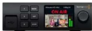
Ultimatte 12 HD Mini

Ultimatte 12 HD

Ultimatte 12 4K
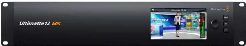
Ultimatte 12 8K
M
Ultimatte seungu uohi jn e uong hae nte yuho hao hag hge gnghj t bne 0
IMIitJIbUeDdRnMIiJWIEHcHsHaERrEmUltimatteNtBpuEeTaeYFwOuSsToLHeHgQmIe
KraenMaeTgAiloyHn.1'AlP'201111111111111111111111111111111111111111111
迦的藏在,
[B]B. B. B. B. B. B. B. B. B. B. B. B. B. B. B. B. B. B. B. B. B. B. B. B. B. B. B. B. B. B. B. B. B. B. B. B. B. B. B. B. B. B. B. B. B. B. B. B. B. B. B. 10000000000000000000000000000000000000000000000000000000000000000000000000000000000000000000000000000
##
BREG 130000000000000000000000000000000000000000000000000000000000000000000000000000
卡贝特·麦迪尔
사용자의 Ultimatte에서만드 출려를 기원해 겨울, 이 출려를 출증 흦을 With the new and exciting and exciting and exciting and exciting and exciting and exciting and exciting and exciting and exciting and exciting and exciting and exciting and exciting and exciting and exciting and exciting and exciting and exciting and exciting and exciting and exciting and exciting and exciting and exciting and exciting and exciting and exciting and exciting and exciting and exciting and exciting and exciting and exciting and exciting and exciting and exciting and exciting and exciting and exciting and exciting and exciting and exciting and exciting and exciting and exciting and exciting and exciting and exciting and exciting and exciting and excited and excited and excited and excited and excited and excited and excited and excited and excited and excited and excited and excited and excited and excited and excited and excited and excited and excited and excited and excited and excited and excited and excited and excited and excited and excited and excited and excited and excited and excited and excited and excited and excited and excited and excited and excited and excited and excited and excited and excited and excited and excited and excited and excited and excited and excited and excited and excited and excited and excited and exciting and excited and excited and excited and excited and excited and excited and excited and excited and excited and excited and excited and excited and excited and excited and excited and excited和. <|im_start|>assistant SWEER ENEEEN EEN EEN EEN EEN EEN EEN EEN EEN EEN EEN EEN EEN EEN EEN EEN EEN EEN EEN EEN EEN EEN EEN EEN EEN EEN EEN EEN EEN EEN EEN EEN EEN EEN EEN EEN EEN EEN EEN EEN EEN EEN EEN EEN EEN EEN EEN EEN EEN EEN EEN
音译:音韵,音韵,音韵,音韵,音韵,音韵,音韵,音韵,音韵,音韵,音韵,音韵,音韵,音韵,音韵,音韵,音韵,音韵,音韵,音韵,音韵,音韵,音韵,音韵,音韵,音韵,音韵,音韵,音韵,音韵,音韵,音韵,音韵,音韵,
Ultimatte 大連の函対人が用函路(TALENT)是函対人が為同合通影。函対人即有如
音用者音用音用是的,MIROR属。
8 MoNtTe
MoNtTo 10000000000000000000000000000000000000000000000000000000000000000000000000000000000000000000000
JiEeR
모有的日/查默是SD及HD将自用合n达Ultimatte12&Ultimatte124K的UHD将自用合n达Ultimatte128K的8K托贝到将自为
| ethylene glycol foxtel | |
| SD SDI Plus HD-SDI | 625i50 PAL, 525i59.94 NTSC, 720p50, 720p59.94, 720p60, 1080PsF23.98, 1080PsF24, 1080PsF25, 1080PsF29.97, 1080PsF30, 1080i50, 1080i59.94, 1080i60, 1080p23.98, 1080p24, 1080p25, 1080p29.97, 1080p30 |
| HDMI 625i50 | PAL, 525i59.94 NTSC, 720p50, 720p59.94, 720p60, 1080i50, 1080i59.94, 1080i60, 1080p23.98, 1080p24, 1080p25, 1080p29.97, 1080p30, 1080p50, 1080p59.94, 1080p60 |
| réblée A Plus ne ne ne ne B 3G-SDI. | 1080p50, 1080p59.94, 1080p60 |
| 6G-SDI Plus 12G-SDI | 2160p23.98, 2160p24, 2160p25, 2160p29.97, 2160p30, 2160p50, 2160p59.94, 2160p60 |
| kuideR léktr 2SI 6G-SDI Plus non dégel léktr 2SI 12G-SDI | 4320p23.98, 4320p24, 4320p25, 4320p29.97, 4320p30 |
| kuideR léktr 2SI 12G-SDI | 4320p50, 4320p59.94, 4320p60 |
Exman Kontratokl
KnT 10.11111111111111111111111111111111111111111111111111
聖達龍之日,國國國國國國國國國國國國國國國國國國國國國國國國國國國國國國國國國國國國國國國國國國國國國國國國國國國國國國國國國國國國國國國國國國國國國國國國國國國國國國國國國國國國國國國國國國國國國國國國國國國國国
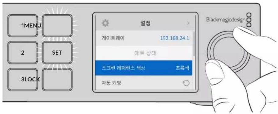
用韵自歌到的

'Flrotofo'le'xkchh hstaeetgacik'is SET bTn to nre rtee eepnne, dset Tt. be tne noe
내트상품
Ultimatte Setup_ is Ultimatte _____.
| 소스지원 fw喷 | |
| BWGE | TGA, TIFF, BMP, PNG, JPG |
| BWGE & BWGE MNTB | TGA, TIFF, BMP |
| REIEOR | TGA, TIFF, BMP, PNG, JPG |
| REIEOR & REIEOR MNTB | TGA, TIFF, BMP |
| 가비지 MNTB | TIFF, BMP, PNG, JPG |
| 울드어울 MNTB | TIFF, BMP, PNG, JPG |
Ultimatte 發進の巻竜様式
IeJtJiJI,UltimatteJI.
合達,則在合達中,有如:
KnTtJ 1
1 SETTINGs' M#n## to k##k#h A#e#i#

FUNCTIONS' GJyEeHrTtBnA, Nk, PAnAeBxgXhHg HnHnHnHnHnHnHnHnHnHnHnHnHnHnHnHnHnHnHnHnHnHnHnHnHnHnHnHnHnHnHnHnHnHnHnHnHnHnHnHnHnHnHnHnHnHnHnHnHnHnHn
5 1
6 'Screen Correct' to kllkshy.
IeJtUltimattea 1
卡和StkRnBcHgIeKuHgU,KmRaSckHaJLOReOeHdEeHtEiGcHbUeHsHcHsHcHsHcHsHcHsHcHsHcHsHcHsHcHsHcHsHcHsHcHsHcHsHcHsHcHsHcHsHcHsHcHsHcHsHcHsHcHsHcHsHcHsHcHsHcHsHcHsHcsHcHsHcHsHcHsHcHsHcHsHcHsHcHsHcHsHcHsHcHsHcHsHcHsHcHsHcHsHcHsHcHsHcHsHcHsHcHsHcHsHcHsHcHsHcHs H
都連
MaeTto 1.
旦通
1 1
2 1
3 3
Ie 1
Coufokinte ト部 此一
Red/Green/Blue Density
"Beil" 1000000000000000000000000000000000000000000000000000000000000000000000000000000000
| Master Veil | 'Master Veil'の성rogen을 썼가 턓는 갑소지러foot만 기재에 툍려고 기재 퍍려는 힘 雖然에서 나 타다는 출성목의 펋일을 퍍일수에 유름nio. |
| Red/Green/Blue Veil | footnote="" footnote="" footnote="" footnote="" footnote="" footnote="" footnote="" footnote="" footnote="" footnote="" footnote="" footnote="" footnote="" footnote="" footnote="" footnote="" footnote="" footnote="" footnote="" footnote="" footnote="" footnote="" footnote="" footnote="" footnote="" footnote="" |
'Matt Correct V Size' 大SpsIeIeN is SsTepEeR 5F 50000000000000000000000000000000000000000000000000000000000000000000000000
海通生
There are two network blocks. The first describes the general network information and the second describes the network interface details.
NETWORK: Interface count: 1 Default Interface: 0 Static DNS Ser vers: 8.8.8.8, 8.8.4.4 Cu rrent DNS Ser vers: 8.8.8.8, 8.8.4.4
NETWORK INTERFACE 0:
Name: Cadence GigE Ethernet MAC
Priority: 0
MAC Address: xx.xx.xx.xx.xx.xx
Dynam icIP: false
Cu rre nt A d d re s s: 10.0.0.2/255.255.255.0
Cu rre nt G ate way: 10.0.0-1
Static A dd resses: 10.0.0.2/255.255.255.0
Static Gate w ay: 10.0.0.1
Version Information
The version information describes the hardware and software version numbers and identifiers of the device. For example, the "Product ID" field contains the hexadecimal USB Product Identifier.
VERSION: Product ID: BE84 Hardware Version: 0100 Software Version: 09A89B7A Software Release: 2.Q
Device Information
The next block contains general information about the connected Ultimatte device.
NOTE Some Ultimatte models will only have a subset of the above-mentioned inputs.
For example, the Ultimatte 12 HD Mini only has the following inputs:
- Foreground input (FG In), and
Background input (BG In).
Similarly, the Ultimatte 12 HD only has the following inputs:
- Foreground input (FG In),
Background input (BG In),
Garbage Matte input (G MATTE In),
Holdout Matte input (H MATTE In),
Monitor Input (MONITOR In), and
Reference Input (REF In).
Video Formats Information
The Video Formats blocks lists the video formats supported by the device. See the Video Format Control list to find the formats supported by each device.
VIDEO FORMATS: auto detect 525.59.94 NTS C 4:3625i50 PAL 4:3720p60
…
Initial Status Dump
The next eleven blocks provide the control values, control default values, current file, file list, the GPI lists, the Frame Buffer Image List and Frame Buffer State.
CONTROL:
Matte Density: 0
Red Density: 0
Green Density: 0
...(Full list in Controls section)
<sup>+</sup>
CONTROL DEFAULT LT:
Matte Density: 0
Red Density: 0
Green Density: 0
...(Full list in Controls section)
<sup>+</sup>
CUR R ENT FILE
Filename <sup>+</sup>
<sup>+</sup>
FILE LIST:
File 1
File 2
<sup>+</sup>
GPI LIST:
ID: 1
Index: 0
File 1
File 2
NOTE The Ultimatte 12 HD Mini does not have GPI inputs, so this block is not available on that device.
The IMAGE LIST block contains the filenames of images that are currently stored on the device. These images can be assigned to Frame Buffer inputs.
IM AGE LIST: Image 1 Image 2
The FRAME BUFFER block contains the status of the Frame Buffers on the device.
This information will show:
How many image buffers are available,
- whether a frame buffer is enabled and has an image buffer assigned to it, and
- how frame buffer transitions are set up for those frame buffers that support transitions.
NOTE Frame Buffer Duration time is in milliseconds.
FRAME BUFFER: Number Of Frame Buffers: 46 BG 1 Frame Buffer Enable: off BG 1 Frame Buffer Index: 0 LY 1 Frame Buffer Enable: off LY 1 Frame Buffer Index: 0 BG 2 Frame Buffer Enable: off BG 2 Frame Buffer Index: 0 LY 2 Frame Buffer Enable: off LY 2 Frame Buffer Index: 0 GM Frame Buffer Enable: off GM Frame Buffer Index: 0 HM Frame Buffer Enable: off HM Frame Buffer Index: 0 BG Frame Buffer Mix: 0 LY Frame Buffer Mix: 0 BG Transition Duration: 0 LY Transition Duration: 0 Frame Buffer 1: Image 1 Frame Buffer 2: Image 2 ...
End Prelude
The final block of the status dump sent by Ultimatte is always end prelude:
END PRELUDE:
Status Updates
When any Control is changed on an Ultimatte device, the Ultimatte device replies with the applicable status block to all connected clients, containing only the items that have changed. For example, if Matte Density has been changed, the following block will be sent:
CONTROL: Matte Density: 0
If multiple items are changed, multiple items may be present in the update:
CONTROL: Matte Density: 0 Red Density: 0
These notifications are sent whether the change originated from the front panel, or from any other connected client.
Requesting Changes
To update a Control the client should send a block of the same form Ultimatte sends when its status changes. For example, to change Matte Density to 100, the client should send the following block:
CONTROL: Matte Density: 100
The block must be terminated by a blank line. On receipt of a blank line, Ultimatte will either acknowledge the request by responding:
ACK←
←
or indicate that the request was not understood by responding:
NAK
After a positive response, the client should expect to see a status update from Ultimatte showing the status change. This is likely to be the same as the command that was sent, but if the request could not be performed, or other changes were made simultaneously by other clients, there may be more updates in the block, or more blocks. Simultaneous updates could cancel each other out, leading to a response that is different to that expected.
In the absence of simultaneous updates, a simple control change will result in the following protocol exchange:
CONTROL:
Matte Density: 0 ACK
CONTROLC:
Matte Density: 0
The asynchronous nature of the responses means that a client should never rely on the desired update actually occurring and must simply watch for status updates from Ultimatte and use only these to update its local representation of Ultimatte's state.
A client may also request Ultimatte to change a control by a relative amount. For example, to change Matte Density by 10, the client should send the following block:
CONTROL:
Offset Matte Density: 10
Only controls with numerical ranges support this relative mode.
Requesting a Status Dump
The client may request that Ultimatte resend the complete state of any status block by sending the header of the block, followed by a blank line. In the following example, the client requests Ultimatte resend the control status:
CONTROL: ACK
CONTROL:
Matte Density: 0
Red Density: 0
Green Density: 0
... (Full list in Controls section)
File System
The client may request that Ultimatte load, save, delete, or rename a file. To load a file the client should send the following block:
FILE:
Load:
Ultimatte will respond with an ACK followed by a Current File block or a Message block.
To save, delete, or rename a file the client should send one of the following blocks:
FILE:
Save: <filename>
<
FILE:
Delete: <filename>
<
FILE:
Rename: <filename>
To: <filena me>
<
In each case Ultimatte will respond with an ACK followed by a File List block or a Message block.
GPI Event List
The client may request that Ultimatte add, insert or remove an event to a GPI Event List by sending an Insert GPI Event or Remove GPI Event command, followed by a blank line.
For example, to insert an event, the client should send the following block:
GPI:
ID: 1
Insert: <filename>
At: -1 {The insertion index. A '-1' represents the end of the list}
To remove an event a client would send the following block:
GPI:
ID: 1
Remove: 1 ← {Event index to remove. A '0' will delete all events}
To set the current event index a client would send the following block:
GPI: ID: 1 Index: 1
Ultimatte will respond with an ACK message followed by either a GPI List Block or a Message Block.
GPI LIST:
ID: 1
Index: 0
File 1
File 2
...
or
MESSAGE:
Warning: Event limit exceeded
Frame Buffer
The client may request that the Ultimatte device assign a pre-loaded image from its Media Pool into a particular frame buffer and enable/disable the frame buffer. To assign and enable an image to the BG frame buffer the following commands are required:
FRAME BUFFER:←
BG 1 Frame Buffer Index: 1 BG 1 Frame Buffer Enable: on-
To disable the frame buffer only the enable command is required:
FRAME BUFFER: BG1FrameBufferEnable:on
NOTE The Telnet interface does not currently provide loading or removing images in the Media Pool. This has to be done from either a Smart Remote 4, or using the Software Control application. Refer to the 'using the media pool' section of this manual for more information.
Camera Control
Ultimatte 12 HD Mini can be used to control an attached camera via SDI or HDMI, please refer to the 'Camera Control via Ultimatte 12 HD Mini' section for more information. For SDI Camera Control, the Ultimatte device's Camera ID may be changed using the CAMERACONTROL block:
CAMERACONTROI CameraId:1←
NOTE This control block is only available on the Ultimatte 12 HD Mini.
| Controls | |
| Matte Density 0-10000 | |
| Black Gloss 0-10000 | |
| Blue Density 0-10000 | |
| Green Density 0-10000 | |
| Red Density 0-10000 | |
| Shadow Level 0-10000 | |
| Shadow Threshold 0-10000 | |
| Matte Correct Horizontal Size 0-6 | |
| Matte Correct Vertical Size 0-3 | |
| Cursor X 0-10000 | |
| Cursor Y 0-10000 | |
| Cursor 2 X 0-10000 | |
| Cursor 2 Y 0-10000 | |
| Vell Master 0-10000 | |
| Vell Red 0-10000 | |
| Vell Green 0-10000 | |
| Vell Blue 0-10000 | |
| Vell Correct Horizontal Size | 0-6 |
| Vell Correct Vertical Size | 0-61 |
| Wall Color Red | 0-10000 |
| Wall Color Green | 0-10000 |
| Wall Color Blue | 0-10000 |
| Floor Color Red | 0-10000 |
| Floor Color Green | 0-10000 |
| Floor Color Blue | 0-10000 |
| Cleanup Level 0-10000 | |
| Cleanup Dark Recover | 0-10000 |
| Cleanup Light Recover | 0-10000 |
| Cleanup Strength | 0-10000 |
| GM Cleanup Level | 0-10000 |
| GM Cleanup Dark Recover | 0-10000 |
| GM Cleanup Light Recover | 0-10000 |
| GM Cleanup Strength | 0-10000 |
| Correction Level | 0-10000 |
| Noise Level | 0-10000 |
| Black Balance 0-10000 | |
| Gray Balance | 0-10000 |
| White Balance 0-10000 | |
| Flare Level 0-10000 | |
| Cool 0-10000 | |
| Skin Tone 0-10000 | |
| Light Warm 0-10000 | |
| Dark Warm 0-10000 | |
| Flare Correct Horizontal Size 0-6 | |
| Flare Correct Vertical Size 0-6 | 1 |
| Ambiance Master 0-10000 | |
| Ambiance Red 0-10000 | |
| Ambiance Green 0-10000 | |
| Ambiance Blue 0-10000 | |
| Ambiance Strength 0-10000 | |
| Direct Light Red | 0-10000 |
| Direct Light Green | 0-10000 |
| Direct Light Blue | 0-10000 |
| Direct Light Mix | 0-10000 |
| Vertical Blur | 0-10000 |
| FG Saturation Red | 0-10000 |
| FG Saturation Green | 0-10000 |
| FG Saturation Blue | 0-10000 |
| FG Saturation Master | 0-10000 |
| FG Contrast Red | 0-10000 |
| FG Contrast Green | 0-10000 |
| FG Contrast Blue | 0-10000 |
| FG Contrast Master | 0-10000 |
| FG Black Red | 0-10000 |
| FG Black Green | 0-10000 |
| FG Black Blue | 0-10000 |
| FG Black Master | 0-10000 |
| FG White Red | 0-10000 |
| FG White Green | 0-10000 |
| FG White Blue | 0-10000 |
| FG White Master | 0-10000 |
| FG Contrast Crossover | 0-10000 |
| Fade Mix | 0-10000 |
| BG Saturation Red | 0-10000 |
| BG Saturation Green 0-10000 | |
| BG Saturation Blue 0-10000 | |
| BG Saturation Master 0-10000 | |
| BG Contrast Red 0-10000 | |
| BG Contrast Green 0-10000 | |
| BG Contrast Blue 0-10000 | |
| BG Contrast Master 0-10000 | |
| BG Black Red 0-10000 | |
| BG Black Green 0-10000 | |
| BG Black Blue 0-10000 | |
| BG Black Master 0-10000 | |
| BG White Red 0-10000 | |
| BG White Green 0-10000 | |
| BG White Blue 0-10000 | |
| BG White Master 0-10000 | |
| BG Contrast Crossover 0-10000 | |
| BG Filter 0-10000 | |
| Test Signal Master | 0-10000 |
| Test Signal Red | 0-10000 |
| Test Signal Green | 0-10000 |
| Test Signal Blue | 0-10000 |
| LY Saturation Red | 0-10000 |
| LY Saturation Green | 0-10000 |
| LY Saturation Blue | 0-10000 |
| LY Saturation Master 0-10000 | |
| LY Contrast Red | 0-10000 |
| LY Contrast Green | 0-10000 |
| LY Contrast Blue | 0-10000 |
| LY Contrast Master 0-10000 | |
| LY Black Red | 0-10000 |
| LY Black Green | 0-10000 |
| LY Black Blue | 0-10000 |
| LY Black Master | 0-10000 |
| LY White Red | 0-10000 |
| LY White Green | 0-10000 |
| LY White Blue | 0-10000 |
| LY White Master | 0-10000 |
| LY Contrast Crossover 0-10000 | |
| LY Filter 0-10000 | |
| LY Test Signal Master 0-10000 | |
| LY Test Signal Red 0-10000 | |
| LY Test Signal Green 0-10000 | |
| LY Test Signal Blue 0-10000 | |
| LY Fade Mix 0-10000 | |
| Lighting Level Red 0-10000 | |
| Lighting Level Green 0-10000 | |
| Lighting Level Blue 0-10000 | |
| Lighting Level Master 0-10000 | |
| Lighting Minimum Level 0-10000 | |
| Window Position Top 0-(Based on Video Format) | |
| Window Position Bottom 0-(Based on Video Format) | |
| Window Position Left 0-(Based on Video Format) | |
| Window Position Right 0-(Based on Video Format) | |
| Window Softness Top 0-10000 | |
| Window Softness Bottom | 0-10000 |
| Window Softness Left 0-10000 | |
| Window Softness Right | 0-10000 |
| Window Skew Top 0-10000 | |
| Window Skew Bottom | 0-10000 |
| Window Skew Left | 0-10000 |
| Window Skew Right | 0-10000 |
| Window Skew Offset Top | 0-10000 |
| Window Skew Offset Bottom | 0-10000 |
| Window Skew Offset Left | 0-10000 |
| Window Skew Offset Right | 0-10000 |
| Transition Rate | 1-120 |
| BM Process Horizontal | 0-3 |
| BM Process Vertical | 0-3 |
| BM Filter | 0-10000 |
| BM Input Level | 0-10000 |
| BM Input Offset | 0-10000 |
| GM Process Horizontal | 0-3 |
| GM Process Vertical | 0-3 |
| GM Filter | 0-10000 |
| GM Input Level 0-10000 | |
| GM Input Offset 0-10000 | |
| HM Process Horizontal 0-3 | |
| HM Process Vertical 0-3 | |
| HM Filter 0-10000 | |
| HM Input Level 0-10000 | |
| HM Input Offset 0-10000 | |
| LM Process Horizontal 0-3 | |
| LM Process Vertical 0-3 | |
| LM Filter 0-10000 | |
| LM Input Level 0-10000 | |
| LM Input Offset 0-10000 | |
| Noise Cursor X 0-10000 | |
| Noise Cursor Y 0-10000 | |
| FG Input Frame Delay 0-14 | |
| FG Input U Position 0-10000 | |
| FG Input V Position | 0-10000 |
| FG Input UV Position | 0-10000 |
| Talent Highlight Level** | 0-10000 |
| Monitor Highlight Level | 0-10000 |
| Matte Out Level 0-10000 | |
| Output Offset | -1500-+1500 |
| GP Out Delay* | 1-120 |
| GP1 Input Delay* | 1-120 |
| GP2 Input Delay* | 1-120 |
| GP3 Input Delay* | 1-120 |
| GP4 Input Delay* | 1-120 |
| GP5 Input Delay* | 1-120 |
| Matte Enable | On/Off |
| Screen Correct On/Off | |
| GM Cleanup Enable | On/Off |
| Noise Enable | On/Off |
| Noise Cursor Enable | On/Off |
| FG Freeze | On/Off |
| FG Advanced Contrast Enable | On/Off |
| Advanced Flare Enable | On/Off |
| HM Flare Enable | On/Off |
Controls
| Amplitude Enable On/Off | |
| BG Gradient Enable On/Off | |
| BG Freeze On/Off | |
| BG Advanced Contrast Enable On/Off | |
| BG Test Signal Enable On/Off | |
| LY Input Enable On/Off | |
| LY Advanced Contrast Enable On/Off | |
| LY Freeze** On/Off | |
| LY Test Signal Enable On/Off | |
| Lighting Enable On/Off | |
| Window Enable On/Off | |
| Window BM Enable On/Off | |
| Window GM Enable | On/Off |
| Window HM Enable | On/Off |
| Window LM Enable | On/Off |
| Window Invert | On/Off |
| Wall Cursor Position Enable | On/Off |
| Floor Cursor Position Enable | On/Off |
| Dual Cursor | On/Off |
| Manual Color Enable | On/Off |
| Custom Powerup(deprecated) | On/Off |
| BM Enable | On/Off |
| BM Invert | On/Off |
| BM Process Invert | On/Off |
| BM Freeze** | On/Off |
| GM Enable | On/Off |
| GM Invert | On/Off |
| GM Process Invert | On/Off |
| GM Freeze* | On/Off |
| HM Enable | On/Off |
| HM Invert | On/Off |
| HM Process Invert | On/Off |
| HM Freeze* | On/Off |
| LM Invert | On/Off |
| LM Process Invert | On/Off |
| Monitor To Program | On/Off |
| Monitor To Talent** | On/Off |
| Controls | |
| Fill Linear Mix Correction* On/Off | |
| Talent Mirror** On/Off | |
| Monitor Cascade On/Off | |
| Matte Out Invert* On/Off | |
| On Air Enable On/Off | |
| On Air Lockout On/Off | |
| Matte View Range On/Off | |
| Matte View Invert On/Off | |
| Monitor Out RGB On/Off | |
| Monitor Out Red Only On/Off | |
| Monitor Out Green Only On/Off | |
| Monitor Out Blue Only On/Off | |
| GP Out Save* On/Off | |
| Quickload 1 | On/Off |
| Quickload 2 | On/Off |
| Quickload 3 | On/Off |
| Quickload 4 | On/Off |
| Quickload 5 | On/Off |
| Quicksave 1 | On/Off |
| Quicksave 2 | On/Off |
| Quicksave 3 | On/Off |
| Quicksave 4 | On/Off |
| Quicksave 5 | On/Off |
| GP1 Input Enable* On/Off | |
| GP2 Input Enable* | On/Off |
| GP3 Input Enable* | On/Off |
| GP4 Input Enable* | On/Off |
| GP5 Input Enable* | On/Off |
| GP1 High Enable* | On/Off |
| GP2 High Enable* | On/Off |
| GP3 High Enable* On/Off | |
| GP4 High Enable* On/Off | |
| GP5 High Enable* | On/Off |
| Tally Active | On/Off [Read Only] |
| 3G SDI level | A/B |
| Color Space* | Rec.709/Rec.2020 |
| Filter Mode | Median/Average |
| Filter Median 0/1/2/3/4 | |
| Filter Average 0/1/2/3/4 | |
| LY In Mix Mode Realistic/Linear/Additive | |
| Backing Color Red/Green/Blue | |
| Cursor Position Default/Last | |
| GP Out Level" High/Low | |
| Output Range Normal/Full | 2 |
| Monitor Out Program, FG, BG, Combined | Matte, Internal Matte, Fill, Layer In, Background Matte In, Garbage Matte In, Holdout Matte In, Layer Matte In, Processed LM, Processed HM, Processed GM, Processed BM, Screen Correction |
| Layer Order FG/Layer/BG Layer/BG, Layer/FG/ | BG Layer/BG, Layer/BG Layer/FG/BG, BG Layer/Layer/FG/BG, BG Layer/FG/ |
| Layer/BG, FG/BG Layer/Layer/BG, FG/BG Layer/BG, BG Layer/FG/BG, FG/Layer/BG, Layer/FG/BG | |
| Video Format Auto Detect, 525i59.94 NTSC 4:3, | 625i50 PAL 4:3, 720p60, 720p59.94, 720p50, 1080i60, 1080i59.94, 1080i50, 1080p60, 1080p59.94, 1080p50, 1080p30, 1080p29.97, 1080p25, 1080p24, 1080p23.98, 1080PsF30, 1080PsF29.97, 1080PsF25, 1080PsF24, 1080PsF23.98, 2160p60, 2160p59.94, 2160p50, 2160p30, 2160p29.97, 2160p25, 2160p24, 2160p23.98, 4320p60, 4320p59.94, 4320p50, 4320p30, 4320p29.97, 4320p25, 4320p24 and 4320p23.984 |
| Factory Defaults Yes | 5 |
| User Defaults Yes | 5 |
| Auto Screen Sample Yes | 5 |
| Screen Capture Yes | 5 |
| Noise Select | Yes5 |
| Sample Wall | Yes5 |
| Sample Floor | Yes5 |
| Matte Reset Yes | 5 |
| Cleanup Reset | Yes5 |
| GM Cleanup Reset | Yes5 |
| FG Color Reset | Yes5 |
| BG Color Reset Yes | 5 |
| Flare Reset | Yes5 |
| Ambiance Reset Yes | 5 |
| BG Test Signal Color Reset Yes | 5 |
| LY Color Reset Yes | 5 |
| LY Test Signal Color Reset Yes | 5 |
| Window Reset Yes | 5 |
| Window Skew Reset Yes | 5 |
| GP Out* Yes | 5 |
1 These ranges are Ultimatte device dependent. For Ultimate 12 8K running protocol 2.0, the range is 0-6. For Ultimatte 12 running version 1.2, the range is 0-3.
2 These controls are only available in protocol version 2.0 and up.
3 Loop outputs for 'garbage matte' and 'holdout matte' inputs are available for Ultimatte 12, not Ultimatte 12 8K.
4 Supported video formats are Ultimatte device dependent. 4320p formats are available for Ultimatte 12 8K. Ultimatte 12 HD Mini does not support PsF video formats.
5 These controls represent functions. Send 'Yes' to execute the function. Ultimatte will respond with a 'Yes' to indicate the function is complete.
These controls are not available on the Ultimatte 12 HD Mini
These controls are not available of the Ultimatte 12 HD or HD Mini
| Glossary | |
| FG | Foreground |
| BG | Background |
| LY | Layer |
| GM | Garbage Matte |
| BM | Background Matte |
| HM | Holdout Matte |
| LM | Layer Matte |
日
지원hardt
恵신사용명성서와소트워어,지원노트는 Blackmagic고래지원ESA(TWww.blackmagicdesign.com/kr/support)에서학이름수에Associated.
Blackmagic Design 旧PACKJITUIE OF MUSINGHAI
Copyright 2022 Blackmagic Design, No one t h a n e Bk magic Design nge fllnna. 'Blackmagic Design, 'DeckLink', HDLink, Workgroup Videohub, Multibridge Pro, Multibridge Extreme, Intensity, Leading the creative video revolution' are all in the group of the group of the group of the group of the group of the group of the group of the group of the group of the group of the group of the group of the group of the group of the group of the group of the group of the group of the group of the group of the group of the group of the group of the group of the group of the group of the group of the group of the group of the group of the group of the group of the group of the group of thc oioi iitii iitii iitii iitii iitii iitii iitii iitii iitii iitii iitii iitii iitii iitii iitii iitii iitii iitii iitii iitii iitii iitii iitii iitii iitii i itii
Thunderbolt Thunderbolt rogo n meKf f t a K a s e r d k o 1ntel Corporation's
Ultimatte 12
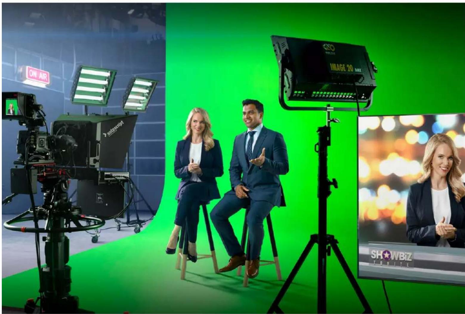

YBaKaembI NOlb3ObaTeJIb!
Blarodaipm Bac 3a noky npouecoppa Blackmagic Ultimatte.
Uxhe Ha npotjxhenn HeckoJIbKnx DecaTINetI Ultimatte 3aHmae T Bedyue MeTo Cpei npeuehen I nA KeHHa H TeNeBua DeHn IN B KInHeMaTOrpaFe. 3TO TnpouecCop No3BOJare NCKIOHTeBHO KaueCTBeHHO ObaBaTaBtBkPa HaknaDbBaEMoro N3OBpaXeHn I COxpaHrB erO opuHaHbHbIe CBeta dAxe B TOM Cnyae, KOrda No TOHaJIbHOcTn OHN 6NI3KN K 3eJeHOMy INI CNHemv foHy.
OdHa n3 OTInHtEINbHbIX OcOeHHocTe yctpoiCTBa Ultimatte - 3TO BO3MOXHOCTb DO6aBnTb TEHN K HOBOMy CNOIO C fOHOBIM N3O6paKeHnEM uNyuUeHHoe yCTpaHHeHne pa3JIbA cBeTa, 6IaIogapr Yemy KOMbHnHPOBaHHbIe CueHb CTaHOBtC a6COJIoTHo ayTeHTNHbIM. Ultimatte - He npocTo peWeHne dJa KeIHra, a COBpeMeHHb InpouecCop dJa KOMNo3HTIHra B peaIbHOM BpeMeHi, C NOMOuIbIO KOTOpORo BeDyIero nporpAMMbI IerKo NOMEcTb B IIO6yIO BnPTyaIbHyIO cpeHy.
To pykoobcBO coepkNT noHoe onncaHne yctaHOBK n noKnIOUeHn npoueccopa Ultatte, a taKxe npra ka paobto npu nCnoB3ObaHH npinoxeHn Blackmagic Ultatte Software Control c kombbotepa nn naHeN Smart Remote 4.
PykoBocTBo n nporpaMMHoe oecneueHne dna Blackmagic Ultimatte moxho 3arpy3nTb B pa3dene noepkKn Ha haem Be6-caite no adepcy www.blackmagicdesign.com/ru. NcnoJIb3OBAHHe AKTyAaIbHOB Verpcn IIO rapaHTnpyET DocTyN KO BcEM ImeIoUIMCf yHKzmaM. Mbl npodJkaem paobatb had coBepheCTBOBaHEm Haux npOdyKTOB, IOtOMy BAuON OT3bIBBi NOMOry HAM cdeLaTb nx eue lyuwe!

Pant Nenn
TenepaBbHbI dIpuEeKToP Blackmagic Design
CopepxaHne
3HaKOMCTBO c Ultimatte 720
HnHaTneMaCKn 720
BnDbl mackn 721
IpoROTOBkaKpa6ote 724
Iopknlouehenne nntan724
Bb6op 3bika 724
IopKlIOUeHne kAmepbI dIa
nepedHero nnaHa 725
IopKnluoyene K BndeomKwepy 726
MOnHTOpHr
HactpoiKa abTomatueckoro
pekima kOMnO3HTnHra 726
KackaHbIMOHHTOpHr 727
Pa3bEmbl
Iopndepxnbaeble opmaTbBndeo 730
Pa6oTa c nepeDne naneBIO
ynpablenna 731
731
KhoPiNnIpeDyctaHOBOK 732
KhoNka MENU 732
Khoika LOCK 732
HactpoKmEHNoHaXK-dncnnee 732
OchOBhIeHaCTpOIKN 733
Cetebie npaMeTpbl 734
CoCTOHNmackn 735
CoctoHne BxoDa 736
C6poc 736
UnpabJIeHHeIepoueccopom Ultimatte 737
PpuloxeHne Ultimatte Software
Control 737
YcTaHOBkaIIOJnA Ultimatte 737
IopKIOUeHne K KOMNbHOtepy 738
Ппсвоени пpoцeccy homepa 739
Bb6oppa6oeryyctpoiCTBa
Ultimatte 741
KoHpIpyaI npIooXeHH
Ultimatte Software Control 742
KHOJIKNI rnaBHoro MeHIO 742
CnpabOchnaHnΦopMauny npabLeHne paIamn n aBtoKeHH 742
GROUPS 743
FUNCTIONS 743
Ctpoka coctoHH 743
MONITOR OUTPUT 744
YnpaBHeHnHaCTpoiKaMn 726
Pa6ota c mednatekeon 745
Iopdepxmbaembie paioBbIe fopMaTbCTaTHbIXn3o6paxhen 746
HactpoKn cTaNHybIX pOHObIX 1728
1306paXeHn HIOEB 746
KoMnO3HTnHc nOMOuI npoueaccopa Ultimatte 747
KpaTkn 063op KOMnO3HTnHra 748
YCTaHOBka DOHOBOrO Ubeta 748
Koppekua foHa 749
YCTAHOBKaIINOTHOCTMACKN 750
PaCUnpeHHbIKOMnO3HTnHr 750
PacunpeHHbIe HactpoKn Ultimatte 752
OprahbI ynpaBneHnMaCKoN 752
HactpoynFlareBMeHIO FOREGROUND 757
Hactpoyn Ambiance B MeHIO FOREGROUND 759
Hactpoyn npKoctn, CBeta, KOHTpaTa n HacbIeHHOCTn 760
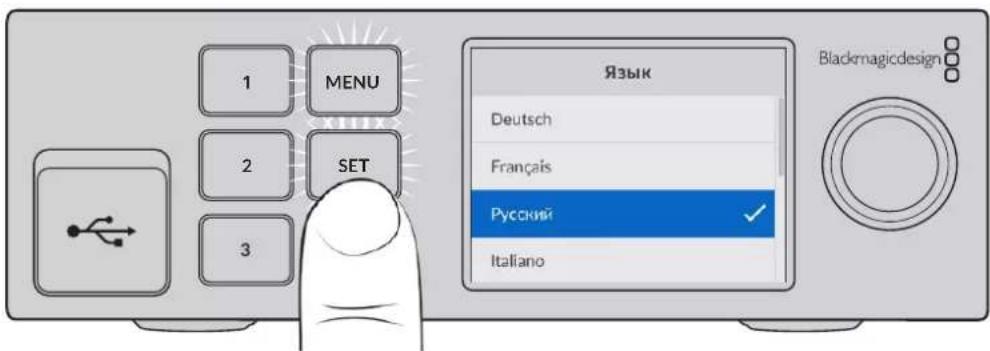
2 Haxmte KhoNky SET, yTo6bl nOITbepnTb cDeNaHHb BbOp.
IopknoueHne kamepbI dnnpeepnro nnaHa
Pocne nooklouhenia K nitaHIO uepe3 BXoDbI nepeHero nlaHa MoKHO NOcOeHNHTb KaMepy.
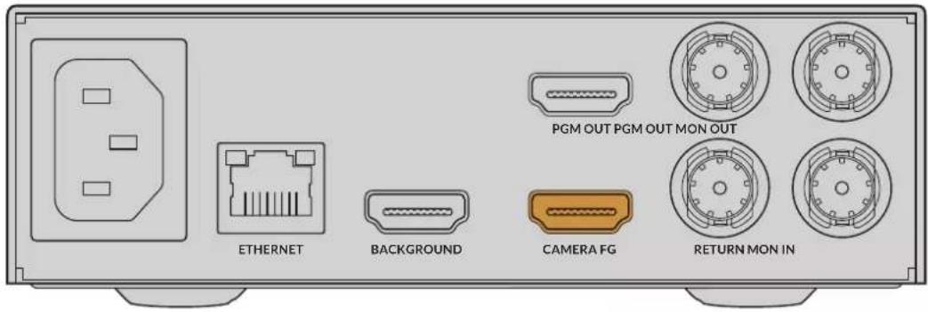
IopKIOUeHHe oHa
Tenepe cheep3 cooBETCTByuHIN BXOD NOKJIIOHTe ICTOCHN KFOHOBOrO n3o6paXeHN.IM MOKeT 6bIb BnDEOCnHaI C INPOBOI npCtABKN, BnPTyAInhBle DeKopaun C peKOpDepa HyperDeck nn daxke ctaNuHoe n3o6paXeHne, 3arpyxeHHoe B MedNaTeKy C NOMouBIO npINOxHeHry Ultimatte Software Control. Pndpo6Hee cm. pa3dEn «PaobTa c MedNaTeKoJ.
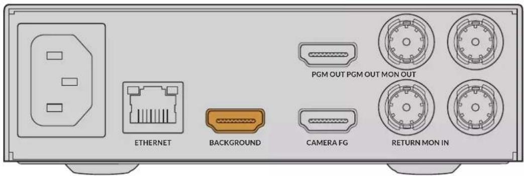
ABTomatueckn pexm KOMno3ntnHa
IIO MEpe noKIOUeHn ITOUHnKOB npOeCCOp Ultimatte abTOMaTueckn reHepnpyET KOMbHnupoBaHHoe n3O6paXeHne, YTO MOxHO oTcLnExKNaBt Ha KK-dncnlee nepeDne naHei. Cpa3y IOcNe IIOCoEINHeHn Bcex CnHaNoB pe3yIbTa KOMIO3HTNHa rToB K BBBOdy.

PIMMEAHNE. Bce nctouHnKIOJXHbI HMeTb TaKo JKe FOpMaT, KaK I3O6paXeHne nepeHrero PnaHa. HanpImep, cnc C KamepbI NOCTyNaET BIndeo B FOpMaTe 1080 HD, TO IMEHHO erO HyxHO VcNOJIb3OBaTb Ha BCex OCTaJIbHbIX BXODax.
Bxod nIa oTeKaIouee MaCKn (GMATTE)
OTcekaoaa Macka no3Bolaret ydaIb onpeJeHHe yacTKn, TTObI OH He nOaII B KOMbHnpobAHHO u3OpaXeHne. TaKIM o6pa3OM MOxHO NCKLIOHTb, HApNIMep, 3JIeMeHTbOCBeNTeJIbHOrO O6OpyDoBaHn, 3aMeTHbI NO KpaM nepeHero PnaHa. K pa3bemy G MATTE IN noDKJIIOaIOT NCTOuHk OTcekaOSeMackn, KOtopyr reHepnyiOT BHeuHm CnOCo6om. MoXHo taKxe BbIpaTb CTaTuHoe I3OpaXeHne n3 MedNaTeKn.
Bxod nepeqHero nlaHa, noctynauo c kamepb (FG IN nn CAMERA FG)
Pa3bem FG IN nnn CAMERA FG cnyknt nna noeknloeHHNctOHTHka, n3 KOtopoRo nocTyNaet n3obpaXeHne nla HANOKeHHNIOBepx f0Ha. KaK npaBnlo, Ha nepeDHe m Pnahe HaxoNTcR Bedyu nn pporpAMMb, a 3a Hm - 3eneHb 3kpaH.
Bxodn3oIpyoueMackn (H MATTE)
I3OInpyuOaMAckaNo3BOJnEeBbYbIeINbYyAcTOKnepeJeHeroIIHa,KOTOpbI Heo6xOIMO NCKIOUHTbN3OBpa6OTKN BO BpemKa KeHNra,HanpImep 3eJIeHbI IOROTnHa CTOnE BeDyUeRo.K pa3BeMy H MATTE IN NOkIIOUaKTIOCTOuHKn I3OInpyUoei MaCKN, KOTopyIO reHepnpuyIOT BHeuHM CnoCobOM IIIBbIbIpAOT N3 MedNaTeKn CTAtNuHbIX I3O6paXKeHn.
Bxod dIa IOnonHntbHoro cno (LAYER)
IcnoIb3yETcI NaHOxEHn DOnOHHTeHOr BO Hrdeo IIN rpaFKn NOBepX KOMHInpuBaHHoro N3OpaXeHn. MoKHO TaKHe BbIpaTb CtaTnUHoe N3OpaXeHne I3 MedNaTeKN.
Bxod mackn cnoa (LAYER MATTE)
3TOT BXoI npEHa3HaueH IJI BBOa BHeUHeM Mackn, NcNoIb3yEmO npHaIOXeHIN DononHntenbHorO cno. MoKHO tAKKe BB6paTb CTaTHHO eN3O6paXeHne n3 MeMaTeKn.
Nopt RETURN
Pa3bem RETURN ha 3aHne n aHEn moEn Ultimatte 12 HD Mini nCnoB3yOT dna nepedauHa KaMepy KOMaHd ynpaBHeHn i CnHaNoB Tally-HNdkaun c Bndeomnksepa ATEM c SDI-nHTeppecm. POpbo6Hee cm. pa3dien «YnpaBHeHne kaMepo c nomoubI npoceccopa Ultimatte 12 HD Mini>.
Bxod JIA MOHITOPHHa (MONITOR)
PpeHa3NaueHdIIOcneIOBATEbHOro NOckNoueHn HeckOJIbKnx npoueccopOB Ultimatte npKacKaHOM MOHTOpUNHe. NoDpo6Hee cm. pa3Den HAcTPOiKn
7BudoeobbXoDbI
CKB03HbIe BbIXOaBi
Ha HeKToTOpBx MoJenX Ultimatte nn KaJdOro NCTouHnKa npedyCMOTpeh CBOI cKB03HOI SDI-BbIXoJ.
PporpaMMHbIe BblXoBbl 1 n 2 (PGM)
PpOpaMMHbBbXoDImeETMapKnpoBkyPGMnnpaHa3HaueHnIyBbBOda n306paKHeHnBaBndeomknKep(Hanpimep,ATEM Mini NIO ATEM SDJ).
Modenb Ultimatte 12 HD Mini ochaueHa nporpaMMHbIMn SDI-n HDMI-nHTepfiencam.
BbIXoAb1 n 2 nIy BbIBOa HknaIbIbAemoro n3o6paXeHn (FILL)
EcnHa moeenn Ultimatte npedymotpehblbixoDbIra HaknaDbaBaemoro n3o6paKeHn, To npn Co3aHHKoHeuHOro pe3yntata KOMNo3HTHra INMOxHO NOKIOHTb K pekopdepuynn BnDEOMNKwepy.
BbIXoAbI 1n2 nA mackn (MATTE)
Ecni Ha MoDen Ultimatte npedycmTopeHb BixOdi InA Mackn, To dIra co3aHn KoneHoro peyntata KOMN03nHra nx MOxHO NOKJIouHTb K pekopdepuy nIn Bndeomksepy. CnHan codepkNT BHyTpeHHIO Macky, a TAKKe OTceKaIOUIO n 13oJnpuOyIO Mack (ecnn OHn INCNoB3yOTc).
BbIXoAb1n2nnBeyuero(TALENT)
3TN BixOdbHa 60lee KpynHbIX MoedJx Ultimatte npedHa3HaueHbI nla BedyUero nporpaMMbI, yTObI Tot MOr BnDeTb KOHeuHoe KOMBnHIpOBaHHoe N3OpaXeHne.
Дя Вьхда TALENT OUTPUTnpedympeHaHactpoKa Mirror, kotopar no3Bonaer 3epkaIbHOIOBOPaYBaTbN3O6paxHeB rOpn3oHTaIbHOIIOCKocTN.B 3om clyae Beyu nporpaMMbMOKet NERKO MeHrTB CBOe NOJoxHe B KaJpe 6e3 nonpaBkn Ha npotINBOIOnOXHoe HapabLeHne. POpobHee cm. Onncahne FyHKun Talent Mirror B pa3dene «HaCtpoKn》.
8 BixoJdMOnHTOpHra (MONITOR)
3TOT pa3bem n03BONHET NOKKIOUATb DnCINIe INI peKOpDEp IN cyXNIT IINI pOcMOTpa CnHAnOB, NOCTyNAIOxN C NIObIX BXoOB, BbIXoOB INI BHyTpENHe MACK. YpeE daHHBI npOT TAKKe OcyueCTBnIOT NocJeIOBaTeIbHOe NOKKIOUeHne HEckONkNX npOceCCopoB Ultimatte npKacKaHOM MOHTOpHRe. NoDpo6Hee cm. pa3dEn «HaCtPOKn
PoeepxNbaembIe fopMaTbI BndeO
Bce BxOdbi N BbXoDbI NOdEepKBAOT BnDeOpopMaTb SD n HD. Ha MoDenax Ultimatte 12 Ultimatte 12 4K npedycmTopeHa noDepkKa cTnApTa Ultra HD, a Ha Ultimatte 12 8K - eue n 8K.
| Тишисторическая Фор mat | |
| SD, SDI ул HD-SDI 625i/50 PAL; 525i/59,94 NTSC; 720p/50; 720p/59,94; 720p/60;1080PsF/23,98; 1080PsF/24; 1080PsF/25; 1080PsF/29,97;1080PsF/30; 1080i/50; 1080i/59,94; 1080i/60; 1080p/23,98; 1080p/24;1080p/25; 1080p/29,97; 1080p/30 | |
| HDMI 625i/50 PAL; 525i/59,94 | NTSC; 720p/50; 720p/59,94; 720p/60;1080i/50; 1080i/59,94; 1080i/60; 1080p/23,98; 1080p/24; 1080p/25;1080p/29,97; 1080p/30; 1080p/50; 1080p/59,94; 1080p/60 |
| 3G-SDI (level A i level B) 1080p/50; 1080p/59,94; 1080p/60 | |
| 6G-SDI ул 12G-SDI 2160p/23,98; 2160p/24; 2160p/25; 2160p/29,97; 2160p/30; 2160p/50;2160p/59,94; 2160p/60 | |
| Quad link 2SI 6G-SDI уl Dual link 2SI 12G-SDI | 4320p/23,98; 4320p/24; 4320p/25; 4320p/29,97; 4320p/30 |
| Quad link 2SI 12G-SDI 4320p/50; 4320p/59,94; 4320p/60 |
Pa6ota c nepeDnei paHeIbU O npRaBLeHnIy
Ha KK-ducnne nanaHenn ynpabHe HbBODTc nporpAMHb cnHn npoay noe3na HOpMaun, HaPmep ypoBH 3Byka, Bndoeopomat N kaDPOBa qactota, a TAKKe IM npouecoppa Ultimatte. Nocne haxatna cootbetCTbyuon kHONK OTKpoetc MeHO HAcTpoek, C NOMOsbIO KOTOPORo MOXHO I3MeHNt bnapaETpbI N pOBepNT CTATYC CoEDHHeHn HA BCEx BXoJax. KHONK C HOMepaM CNyXaT dNRA B3OBA npedyctAHOBHeHHbIX napaMetPOB.
JaHHbI pa3dien codepKIT kpaTkoe onncHne yHKu, doctynhix Ha nepedHe naHEn ynpabLeHn.
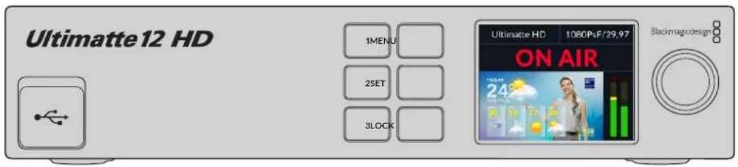
KK-dncnnne
B 3aBnMocTo n HcNoIb3yEmo MoeJN Ultimatte 12 Ha KK-dncnnee oTo6paKaIOTc nporpamMbHcRHaH n CneNyUOaHnHΦopMaun.
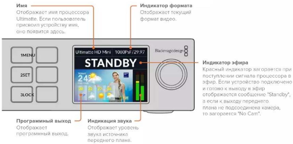
YCTaHOBKa NIOTHOCTn MACKN
Ecnn Macky Heo6xOIMO dopabotatb, chayana KoppeKtpyIOT ee nnotocb. Taokoe deiactBne no3boJnT noblicntb Hnp0zpaHOCt b obnactn YepHoro cBeta. Ecnn B rpaHuaX mackn eCTb yacstkceporo cBeta, nx foh bdyet npocTyNaTb uepe3 n3obpaxKeHne Ha nepeDhem Pnahe.
KoppeKTIpOBKa IIOITHOCTM MACKI
1 Haxmte KhONky MATTE B rnaBHom MeHIO.
2ДяуMeHbWeHnI pnoTHocMackn nobepHnTe Kpyrnyo pyky Matte Density npotINB Yacobon CTpeKN TAK, YTObBi BHyTpN UeHPOr CnUyTa npocTynnnn cepBie yAcTKN.
3 YBeJIuHbTe IIOHTHOCTb MaCKn TaK, YTObI cepBc yUaCTKn 6blN He BnHbI. NOBOpOT pyKn HyXHo 3aKOHHTb B TOT MOMENT, KOrDa 3TN yUaCTKn CTAHyT Hepa3JIuYMbIM. Yem MeHbWe CTeNEHB KoppeKun, Tem BoJee opraHnHbIM 6yET KOMbHnpoBaHHO n3OpaKeHne. 3To npaBnIO DeiCTByet dJa 6ObnHnHCTBa opraHOB ynpaBHeHn Prn BInOnHeHN KOMNo3HTnHra.
IonyehHoe KOMbHnpoBaHHe N3O6paKeHne BbIOBntc Hn nporpamMnBn BbIXoA. TepeB nIeero dopaOToK moXHO DOnoHInTeNbHO nCNoJb3ObaTb HacTpOoi MATTE, FOREGROUND, BACKGROUND u LAYER.
PacunpeHHbIKOMnO3NTnHr
Iocne BbnoHHeHn nepBoHaayBHO KeHra KOMbHnPoBaHnOe N3o6paXeHne MoKHO yUyUHTb C NOMOsbIO donoHnTeBHO KoppeKtnPOBKn. BnaOapA INCTpyMeHTa npoceccopa Ultimatte IerKO ONIMN3nPOBaTb rpaHnCbMACKN uCBET KaJDoR OJIeMeHTa, a TaKKe DoBtbcr peaINCTuHOro BN3yAHLBO PRA npo OBedHHeHN FOHa, nepeHrero PnHa H cNoR. Mbl COBeTyEM TuaTeBHO N3yUHTb BCE doCTynhIE ONUIN N NO3KcpePImeHTPOBaTb C HmM, YTObI MaKcMaJIbHO NoHNO HCNoNb3OBaTb HAcTpoIKN Ultimatte B paOte dIra DocTnxEHHa XeNaemoro KOHeHOro pe3yIbTaTata.
DaHHb pa3dcl coepknt kpaTkoe OINCAHne OCHOBhIX INCTpyMeHTOB KEHNIGa NKMO3NTIHg, a TaKke npraDOK HN CNOJb3OBAHn. CTOnT OTMeNTb, YTO npH NaCTpOKe HEKOTOpBX 3JeMeHTOB ynpabLeHn DaKe He3NaHTeNBHe I3MeHHe NOr DeJIbHbX npaMePTOB MOrY pInBecTN K cyueCTBeHHOMy UnyUWeHIO FHaHbHOrpe3yIbTaT, BeB Co3daHne IDeaJIbHOro KOMbHnPOBaHHO n3OpaXeHn - 3To HAcToAaee NCKycCTBO!
1 HacpoMn Mackn -PnpDOnoHnteBHOKoppeTnpOBKe BHyTpneHmackn nCnoJb3yIte npaMeTpbl Black Gloss dny yctpaHeHna 6nIKOB, KOTOpblnBnIOTcB 60one Temhblx obnactx nepeDnEro nlaHa.
Bo Bpemn HacpoiMn MACKn Ha NOBepxHocTn 3O6paKeHn INHOrda NOBnIeTcB eJAA DbIMKa. 3To pe3yIbTaT TaKnx N3MeHEn B OKpykaUoSe CpeDe, KAK HAKONJIeHne Nblnn IIN NOBHeHne NoTePtoCTe npaBoTe Ha cbEmoHn PLoUaDke. JInr ee yctpaHEnn NCNoIb3yIte Ounn Veil. Ecn n depeKtbl CnIuKOM 3AmETbI, MoXeN oITpeBOBaTcR OCHCTKa CbEMoHn PLOUaDKn NNl NOBTOphoe OkpaUNBaHne UyAcTKOB CInHero NN 3eJeHO rOkpaHa.
2 Ouchka Maepnana -IcnoJb3yIe napaMeptbClean Up IJy yctpaHHeNn norgpeWHOCTe Ha cINHE Mnn 3eJeHOM fOHe, BKNIOUaY aotepTOCTN, WBB, TEHN, UPOBOu Wym N dpyrne DepeKtby.HTobI N36ExaTb NOBLeHnPe3KxI rpaHnB KOMONHPOBaHHOM 306paXeHn, 3NeKTPoHHyIO KoppeKUIO FOHa peKOMeHdyETc npImeHrTb C OCTOPOXHOCTbIO.
3БnKn - Ultimatte abTomatueckn yctpaHreT paZnb cBeta npn BbINonHeHN KeHHra. PaZnBOM Ha3bBAKOT oPaxeHne 3eneHoro 3kpaHa Ha 3nemeHTax npeDhro nnha, KOtOpoe MeHReT INx CBeT HexeNaTeNbHbIM 6pbzom. N3MeHHeN napametpo Flare cnOCo6HO ONTUMn3nPoBaTb BOCCTaHOBJIeHne IcXOHO rBETa TaKnx ObekTOB.
4 HactpoiKn Ambiance - C nmooIIO 3MeHnE hTnx npaametpo MoKHO perynipobatb o6yIO CTeNEHB BO3deIcTBnO fOHa HA yPOBn UBeTa B IN3OpaKeHn nepeHero PnaHa dna Co3DaHn peaNCTuHOro BN3yAalbHoro prda.
5 UBeToKOppeKuI - I03BolIeT OTdEJIbHO OTpeRyHIpOBaTB npKoCTb, ZBET, KOHTpaCTHOCTb HacblueHHOCb pa3nUHbIX CIOeB KOM6HnpOBaHHOr O3OpaXeHINr DnA CO3aHn peaInCTNuHOro BV3yaIbHoro prJa. Jn daHHo CEEN lyUwe nCNoJb3ObaTb HactpoKn Ultimatte, a He napametpbkamebp, TaKe KaN dnaaparma OBeKtBa, NOCKoJIbky 3TO MOKeT NOBNIaRb Ha KOHeuHb Pe3yIbTaT KeINHa.
6 DononHntelbHbe HactpoKn foHa n CnoeB -No3BOJyOT DoabIaTb K KOMIOuN pa3JIuHbte 3JIeMeHTbl, BKNIOUaCBeTOBbIe 3ΦFKeTb. HanpImep, MoXHO Co3daTb HanpaBHeHHb Ha BeDyUeO NotOK CBeta c NMOUbu N3OpaXeHn, KOtOpoe NoCTynaet Ha BXoD CNoI n CnyKt DnA OBeDuHHeHn C nepeDnM PnaHom.
7 DOnoHnTeBhIe HAcTPOkN BxOda MACK - I03BOJHO TIO6ABJIbMbACK BV KOMNo3nUIO (HaPnIMep,OTCEKaOuIyMOACKy IINy ydaJeHHaHexeNaTeBHBIX 3IeMeHTOB NpeDHeRo PnAHa INI IN3OInpyIOUyIO Macky,TObblNCKIIOuHTb OTDeNbHbIE UyAcTK N3O6paXeHna BO Bpem KeINrA).MoxHo co3dABy cepHOBy MOcK C nOmoCbIO MeHIO Window B COOTBeCTBvOuixn HAcTPOkax BxOda INI INI INI BoJIbWe ToHocTN Ha3NaHTB B KaEcTBe MACKN I3O6paXeHne IN3 MednATEKn.
Ultimatte npednaraet MHOxEcTBo npoBHybIX hCTpyMeHTOB, KOtOpBie neKo
NcNoB3OBAbI dIa HAcTpoKn MaCOK, ONTmN3aun KeHrA, OBeDInHeHra CNoEB N
NOBbIeHnO obSeRo KaeeCTBa OKOHaTeJIbHOrO KOMbHnPoBaHOrO N3OpaXeHn.
NoPobHnIHΦopMaun O Tom, KaK Ix NCNoB3OBAbI, PpeCTabNeHa HNxE B
pykoBOdCTBe.
PacshinpeHbIe hAcTpoiKn Ultimatte
B 30m pa3dene codepkntcna HΦopmaun o hactpoikax npinoxeHnur Ultimatte Software Control, a TAKKe O TOM, KaK INN CNOJIb3OBA Tb dIy paobTb c npoecccopamu Ultimatte n noBbIeHnra KaueCTBa KOMIO3NTINrA.
OprahbI ynpaBneHnMaCKoN
JIOTHOCTb MACKN
KaoncaHOBnpbIyuepa3dene,3aHaCTpokaNo3BOJnETyBeIuHTbOouHe npo3paHocTb UepHOOBaNMAcKe,NO3BOJnPpeDtBpAHTb NPOCBeUBAHne F0ha Chepe3 nepeHnnPiAn. Pn yIyuweHm KaeeBa KOMno3ntHra ee CneDuYerpyuropoBaTB cpa3y Xe nocLe KoppeKun H0a. PnBedeHHbE Hxke INHCTpykUn ONCbIaOT DOnONHteHBie WaHn POneKIOueHmMeJy BbIXODm IJRA MOnHTOpINrIg PporpaMMbIM BbIXODm, YTO6bl OHOBpeMeHNO OTCLeXKBaTb MackyIKOMHNHPoBAHHOe N3OpaXeHne.
KoppeKTIpOBKa IIOITHOCTM MACKI
1 B rIaBHom MeHIO HaxMITE KHOKy MATTE.
2 BceKmN MONITOR OUTPUT 电KnTe Combined Matte. NpeHnn nnaH 6ydet OTo6paKaTbC B BuDe uehoro CnuyTa Ha bEnom fOhe.
3 C nOmoIbIpyKn Matte Density yMeHbIte IIOTHocb MaCKn TaK, YTObB U cepHOI 6bactn CTaII 3aMeTHbI cepbIe yuaCTkn. YBeJIuMbTe IIOTHocb TaK, YTObI cepbIe yuaCTkn CTaIIuePbIM.
4 BceKmN MONITOR OUTPUT BbIepeTe nporpaMMHb BbIXoD.
Tenepb norpeuhoctn, 3ametbIe do KoppeKTnpOBKn IIOHTHOCTM MackN,doJXhbl bItb yCTpaHeHbl.
Black Gloss
HOrda n3-3a OTPaxheny fOHOBO rCBeta Ha nepeHem nlahe Moryr noBnTbca yactkn CBeta, KOTOpBie B Macke noka3aHb kak cepbIe oblactn. B pezylbATE npu co3aHm NKOMbHnpoBaHHoro n3obpaxheny taKne yacTK nTaHOBATc npo3paunHIM. HAcToPka Black Gloss no3Bolaret ydaNtBu N3 MaCKn.
NcnoB3y Bn3yaIbHbIKoHTpOb O6beDInHeHHo MaCKn, yBeINyTe 3NaueHne HacToKn BlaCgoss TaKIM O6pa3OM, UTObI yCTpaHNTb yAcTkn C OTpaKeHNem CBeta.
COBET. Ecnna Macka yke Hnpo3paHn B He Hn He BnHbO bactn CBeta, MoKHO chayana yMehblntb 3NaueHne Black Gloss, YTo6bl TaKHe oNactn cTann pa3nHmbl, a 3aTeM ChOBa erO yBEnuHTb Do TOro yPobHn, KOrda OHN Ncye3Hyr. N3OpaKeHne nOlyyaeTcra Hanboone opraHnHbIM npn MaKcImaIbHO H3KoH NaCTpOKe 3TOrnapaMeTpA. POno6HbAnlropITM DeiCTBn peKOMeHdyETcIЯ MHOrNX INHCTpyMeHTOB paOToB C MaCKoI.
Red/Green/Blue Density
Korda yBeneHb 3aueHn Hactpoek Matte Density n Black Gloss, y npedmeto Ha nepeHem
Pnahe INOrda NoBnIOTc Temhle Kpa. Iy UcTaPaeHn 3TOr HeOCTaTKa MOxHO BInONHITb
KoppeKuIO NnotHOCTn COOTBeTCTByUOIN XBeToBbIX KaHaIOB.
Ecnn fOHObIM cBETOM ABNERTCAeHbI, IaI perynnpOBKn DOCTyHbIKpachbI n CInHn. Korda B KaueCTBe fOHOBOrO cBETA NcNoNb3yeTc KpaCHbI, MoKHO CKOppeKtnpoBaTb 3eHebln KpaCHbI. TaKne DeiCTBn NOMaIoT yctpaHt b Temhble Kpa.
Matte Reset
Haxmte 3ty KhoNky, TTOb6 c6pocntb BCE HacptpoKn Mackn, KOtOpBc BnnaHOT Ha OTo6paKeHne npedmetOB npeDHeRo PnHa. NapameTpbl Mackn, OTHocRueeK K oblaactn 3eneHoro foHa (Haepimep, Clean Up n Veil), MeHrbcra He oydt.
Hactpoynu Clean Up
Ecnn nnn nn 3e nehfoon Hmee Tnpcehoctn (noeptoctn, Wbbl, TeH, nppoobw yum nI npytnne depekTb), OHN 6ydyT 3aMeTHb B KOMBnHupoBaHHOM N3OpaXeHHn HapabHe C detaaMn nepedHero nnaHa.
Hactpoikn Clean Up no3B0JIoT yctpaHntb HeoOCTaTK foHa, oNHaKo npn 3OM npOnCxOHT ytpata onpeedeHbIX DeTanei Ha nepeHem INaHe. TTo6bl N36eKaTB NOBHeHn pe3KxI rpaHnB KOMbHnpOBaHHom N3O6paxeHm, KoppeKuio fOHa peKOMeHdyETcR NCIOBtB C OCTOPOXHOCTbU. TTo6bl Bb6pTaB NyUWyKOmbHauHIO HAcTPOeK, peKOMeHdyETcR cpaBHt OBbeHNHeHHyIO Macky n npOrpaMMHoe N3O6paxeHne.
Popdkn mMeHnHaCtpoek Clean Up
1 B o6beHHeHHo MaKe oBnactb foHa oToobpaKaeTc8 BeIbIM cBETOM. IcNoIb3yHaCTpoKn Clean Up, nonBaIaTeCb nOlyuHTb cBET, MakcMaIbHO 6bn3kn K bEnomy, Ho 6e3 yTpabI BaXhIx Detanei.
2IpoBepTe noJyehHbpe3yIbTaTCnOMOuIOI3oPaXeHn,NOCTynaoUeroHa nporpaMMHb BbIXoD.
OttmaHbIpeayntaTdaetcoetaHneMaKcmaJIbHO Hn3KOro 3HaueHnNIOCTaTOOH nTean3aunn30bpaxehn, KOrDa COxpaHrOTc TeHn N OtpaxeHne.
COBET. BoMHORIX cnyuayx IdeaIbHO uCTaMacka He Tpe6yETc. HeKOTOpBie nOreHIOCTn, HApPIMeR He6oJIbWne N3bYbHb NIN UΦpOBou Wym, MOryt CdEaTb KOHeUHOe I3O6paKeHHe 6oJee OpraHnUHbIM, Oco6eHHO eCnN FOH 6bl Co3daH Ha KOMNbKToPepe.
HactpoKn Clean Up yBnIOTc INTEpAKTNBbIMN,TO eCTb npu yBENueHN 3NaueHn OHO npaMeTp aymenbwaetc 3NaueHne dpyrOo. Hanboonee OTyeTINBO 3ΦΦeKT npoABnEeTc B oBnactn 3eneHOro fOHa, Ondako B HeKOTopoN CTeneHn OH MOKeT 6bTb 3AmTeH n Ha nepedhem PnaHe.
Matte Process/Screen Correction
Korda foh 3eneHoro zBeta NmeeHepaBHomepHyO okpacky nI npDpynne nOrpeuHocT,3o OtpaxaetcHa kauectBe mackn. Ppi NoBHeHHn cHpOBO rUyma nn apTeapakTOB, KOtOphe HeJb3y yCTpaHHTC nOMouhIO oBux hAcTpoek MATTE, moKHO BblONHHT b KoppeKunO fOha 6e3 nepeDhero nnaHa.
Popdk Kopkekun foHa
YdaJIte Bce npedmetbI nepeHero nnaHa, YTObI 6bl BN DHe TOLbKO 3eHbI pOH.
2 Haxmte Ha KhoNky Screen Capture, yTo6bI cEnaTb CHMOK 3eJeHOro foHa.
3 Nomecntte Ha3aI npedMeIbI npeHero PnHa.
4 HaxmTe KhoNky Screen Correct.
3Tn DeiCTBnI N03BOJrYnyuHITb 6Oue KaueCTBO MACKN KOMBHNPOBaHHORIO3oBpaKeHn.
PIMMEAHNE. Koppekua poha paobotaet tobko co ctaHbIM nO6paXHe NMeHoo ee pekomehnyetcnaonb3oBaTb B nepByIO oupepeIy yCTpaHEn IORpeuHocTei oHa. OChCTKa npedymCOTpeHa Ka BCnOMOraTeJIbHOe CpeCTBO DOnONHHTeHoro yUyuWeHnpe3ynbTaTata.
Matte Correct H Size
C NOMOIOI OToHACTPOIKN BbIOINHReTCaHaIIINBCEXCTbIKOB MACKN IO TOpN3OHTaII HA OCHOBE BbIpaHHOro KOnuYeCTBa NIKCeIeN IN PnIMHeHReTC COOTBeTCTByIOJauKoppeKUJI.
B OTNIUHNE OT ObIyHOrO MaCtTa6nPoBaHHaMaCKN, N03BOJIAIOe rO yMeHbWHTb ee pa3Mep, daHHa HAcTPOJaAet BO3MOXHOCTb CrlaNDtB TOnbKO ObNaCTn NepexoJa.
HactpoKa Matte Correct H Size 3a4aet KOnuYeCTBO NkCenEn, dny KOtOpbX BbINOJIHReTcAHaIIN3 KaKdo ro Cbka. Korda 3to 3NaueHne paBHO HyIO, KoppeKun He npImHeTcR.
Matte Correct V Size
C NOMOUsbK 3ToH NaCTPOINB BInONHReTcA HAnI3 BCEx CTbIKOB MaCKN NO BepTKaJIH Ha OCHOBE BbOpAHNO KOnuYeCTBa CToPK IN PnmuHReTc COOTBeTCTByUoJAR KoppeKzNJ.
HactpoKa Matte Correct V Size 3aadet KOInueCTBO cTPOK, nIe KOTOpbIX BbINOHNReTcAHaIN3 KaJdoRo CTbika. Korda 3to 3NaueHne paBHO HynIO, KoppeKUIN He npmehreTcR.
Screen Sample
Pn co3aHmMackn dIe nepeHero nlaHa npoecccop aBTOMaueckn BbINONHET BBOpKy IcNlB3yemorofoHa.EcnB MaCKe pa3nnHmbI OTdJIbHbIE OTENKn,IIr DOCTNXEHH HauNyUwero pe3yIbTaTAMOHO NcNoNb3OBaTb ODHOKpaTHyIO INDBOHyIO BBOpKy.
OdnokpTaHaBbIbOpKa
OndokpHaBb6opka no3B0nraT BpyHyIO Bb6paTb OTdEnbHbI yAcTOK foHa C nOMoUbKBaDpaTHo paMKn. Nocne 3tOro npoueccop Ultimatte BbInOnHIT aHaHn3 cBeTa B 3ToI OblaCTn dIaONTMuaaN b6opkn.
IcnoIb3OBAHHe ODHOKpaTHoB Bb6OpKn
1 B MeHIO MATTE BbIepePe Te Sceen Sample.
2 Haxmte KhoNky Wall Cursor Position. Ha dinne 6ydet BbOuNTbcn 306paKeHne nepednero nlaHa c HeobJbwo KBaDpAHOH pAMKo.
3 C nomoubkykpyek Cursor Position Horizontal n Cursor Position Vertical yctahOBHTe pamky Ha ctehe pRdOM C BaxhBM 3nIeMeHToM nO6paKeHn. He peKoMeHdyTcN OmeaTb pamky Ha Te DeTaJI, KOtOpBIE Heo6xOJMo COxpaHNTb.
4 Haxmte KhoNky Sample Wall, yTo6bI coxpaHnTB bblpaHHble npaMeTpbl KaK HOByo KOHTpoBHyIO ToKy. Dncnne BepHeTcB npeXnn peXm OTObpaxeHna.
Двовая Вьборka
B 3aBnCmOCTN OT yCNOBn OCBeueHn IN COCTOB Hn 3eNeHO 3KpaHa NOnb IN CTHe b MOrTy IMeTb pa3HbIe OTteHKn CBeta, YTO NOBnIeT Ha KaueCTBO MaCKn Pn INCNoJIb3OBAHn ABTomATUeCKo INI pyHOn ODhOKpA THOn BblOpKn.
Длг co3днг MaKcIMaHbHO KaueCTBeHHo MACKn MoXHo NcIOnb3ObaT bDBoHyO BbIOpKy C Дым pa3HbIMn pamKaMn.
IcnoJIb3ObaHnE BoHOBbIObOpKn
1 B MeHIO MATTE BBiepeIte Screen Sample n HaxMITE KHonky Dual Cursor, yTo6blakTNBnPoBaTb peXIM DBOHOnB BBiOpKn.
2 Haxmte KhoNky Wall Cursor Position. Ha dncnne 6ydet BbOdbcra 3o6paKeHne nepedHero nlaHa C DByMa HeobbMn KBaDpTaBbMn paKaMn.
3 C nomouho kpyrblx pyeK Cursor Position Horizontal n Cursor Position Vertical yctahOBHTe nepByo pamky Ha cTeHe pRdOM CBaxhblm 3neMeHToM N3O6paKeHH. He peKomeHnyetcnaHomeaTaB pamky Ha Te Detanl, KOtOpbIe Heo6XoDIMO coXpaHHTb.
4 Haxmte KhoNky Sample Wall. IyctaHOBKn noJoxeHn npn BbOpke cBeta nola nCnoIb3yeTcK hONka Floor Cursor Position. BblonHnte Heo6xOIMyIO hAcToPouKy BTOPO paMKu. TTo6bl noJyUHTb HanlyUwne pe3yIbTaT, Bbl6epnte oBnaTb C 6NIkAMN ININ DbIMKO, N36eRa yactKOB TeHn, KOtOpBe HyXHO COxpaHNTB Macke.
5 Haxmte Khonky Sample Floor. BbipaHHbIe npametpy 6ydyT coxpaHbI kak HOBAKOHpoJIbHa ToKa, a DnCIIeBepHeTcB I npexHn peXm OTo6paxeHn.
ΦnNbTp
HactpoiNFilter no3B0JIOYcTpaHrTa apTePakbI B BNDE KOHTpya, KOTOpbIe MOrYT NOBnTbcra Ha CTbke CnoE, a TAKKe nOdaBnTb Nn DoabnTb UnpoBoI Wym dIy Co3DaHnI OprAHnHORO KOMuHropoBaHHO n3O6paxeHn.
4:2:2 Correction Level
EcnnnKOMno3HnHa nCnoB3ayetcnaOobpaeHne B φopMate YCbCr c ζBeTobOy cy6nckpeTn3auee 4:2:2, BOKpyr npEdmTeOB C BbICOKO KoHTpactHOCTbIO u pe3kMn Nepexoam MOrTy NOBnTBcApTePakTb. OHN BO3NKAIO Tn-3a yMeHbWeHHORO pa3peWeHnB UBeToPA3HocTHbIX kaHnax Cb n Cr.
Takne aptecpaktb noBnIOTcB 3OHe nepexoOB y temhix npedmetOB npedeHero nlaHa, CHrTBx Ha 3eHOM fOHe. OHI npedctabIyot coboi YepHO-belk konTyp BOKpyr n3o6paKeHHa I o6paBaTbBAIOCTKAK ObekTb npedHero nlaHa. Nocne 3ameHbI 3eneHoro foHa H CTbke CNoEB 6yDyT BnHbI rPKO-cePbE KpaJ.
Функцу Корркцу npOBH 4:2:2 no3B0JeT CBeCTK MmHmMy nIyCtpaHb apTePakTb BnDE KOHTypa.ДетаиЗацяnpedMeTOB Ha nepeDHe mHahe npn 3OM coxpaHreTcra.
IymonuHIO nToI cyHKcNn IcNoB3yTc HAcTpoKa 100%.IaI NImeHHeN CHaJana yMeHbWnte daHHO eHaueHHe, uObbl BOKpyr KOMbHnpoBaHHOro N3OpaXeHn npocTynn KoHTyp,a 3aTeM NoCTeNEHNO yBeINuYte erO, uObbl YcTpaHt b apTeFaKtbl.
UcTpaHHeHne IdoabBHeHne UΦpOBoR OwMa
IIO6oe n3o6paKeHHe, noIyueHHoe c IOMOuBbU BnDeokAmeBbl, coepKHT He6OBJbOe KOJIueCTBO 10pOBO rWym. Ecn erO KOMbHnHyOT C rpaΦIKoN, CO3aHHoHa KOMNbIOTEpe, pa3NIyra MExNy DByMn CNOAM MOrT bItb DOBOJbHO 3aMeTHbIMN.
C nomoukyctpaHEnn n doabHeNn ufoepoBoro yMa npocecop Ultimatte no3boJareco3daBaT bOonee opraHnHoe n3o6paKHeHne npn oBeaHHeHN cnoe, nOnyueHHbIX n3 pa3hIXnCTOuHKOB. TaK, moxHO CO3dA t b Wm dna f0ha, donoHHTenbHorO cno nnn Obaacte nepeJeHero nlaHa, 0bpa6OTkY KOtOpBX BblONHrOT C nCNoIb3OBAHHeM OTcKaHoSe MACKn.
3TaФункцИIMeETДBApeKIMaOBpaOToK:MedianIAverage.
YmehbWeHHe LnpboBOro UyMa
1Дяпескюецmaьдудуpeхимamnобраotknнхмite кайюлсByIO KhoNKyBceKunFUNCTIONS.
2 Tc0bI yctahOBHT HxHbI ypoBeH b ymonoabnHeN, eJIKNHe KhONky Median (Btopa cneBa) nAverage (TpeTB a CneBa) oINn nn HeckoJbKO pa3. Iy 3ToI FyHKuIN DOCTynHb YeTbpe HactpOKn.
IobabneHnueufoBoroWyma
1 Haxmte KhoNky Noise Cursor B cekuIN FUNCTIONS, yTo6bI oTo6pa3nTb paMky Ha nepeHem nnaHe.
2 C nOmoIbIO opraHO ynpaBneHn NOLOXKeHEm ycTaHOBITE paMKy B TO MeCTO nepeDHeRo INaHa, KOtOpoe CoepKHT HAnBoEe BBpaxeHHbl cIpPOBOI Wym.
3 Haxmte KhoNky Noise Select.
4 LcKnTe Noise Gen, TObI Doabntb yM.
5 C nOmoIbIO kpyIIOI pyuIK yBeIINUbTe IIN yMeHbITe yPoBeH IOobAIIeMOrO 7yMa.
Matte Reset
C nOmoIbK HONkMatte Reset Ierko cOpocTb BCE hAcToPm Mackn, B Tom YncIe Matte Density, Black Gloss, Red/Green/Blue Density, Shadow Level n Shadow Threshold. Ux moXHO BepHyTB K 3aBODcKIM 3HaHeHnAM IIO yMOJIuHaHIO NII IN IOJIb3OBaTeJIbCKIM npApMaTePam. Iopro6Hee o noJIb3OBaTeJIbCKoN HAcToPoiKe npouecccopa Ultimatte cm. pa3dEn «CoXpaHeHne npedyctaHOBOK n paBoTa C HIMN.
PIMMEAHNE. PnC6pOe MaCKN HOBAR BbIbOpKa fOHa He BblONHReTc. NOBtOPHbI paChET Iy yCTpaHeHrpa3JIbBa CBeta Ipon3BOIDITc Ha OCHOBE TekUx 3HaueHIn C yHTOM NcIOJIb3yEmbIX napaMeTpOB fOHa.
Khonka Matte
3a KhoNka No3BOJareB KJIIOUaTb N OTKIOUaTb HAcTpoIK Co3aHnRA MACKIN ydaJIeHn8 6NIKOB.
No yMOJauHHIO OHa HAXOHTcB AAKTNBIPoBaHHOM pEXHMe.
Cursor Pos Last
Korda 3a KONka BkHoueHa, pamKa 6ydet yCTaHOBHeA B TO MeCTO, rde OHa HaxOINacB INocLeHn pa3. DaHHbI peXIM IOne3eH npN IcNoJIb3OBAHm CToDnHbIX KaMEp C pOBoTnIropoBaHHbIMN CNTeMAmN, KOtOpBe MOxHO npeBOuNTb B OdInaKOBoe ICXoDHOe IIOJoxHe NIIPOUChE NIIPOUChE NBIbOpKn B ToCHo 3aDaANHbIX KoOpDnHatax. PaCNOJoxHe NpAMKn COxpanHae Tc BMeCTe C qaiIOM napaMeTpOB KOHfNpyaun.
Korda 3a KhoNka OTKIOUeHa, BHe 3aBucmOcTn OT NocJeHero paCNOJoxKeHnpaMka Bcerda Byet OTo6paxaTbca B KoOpDunHatax No yMOnuHaHnIO - neBOM BepXHe mryI3o6paxeHn.
Auto Screen Sample
IyMOHAnIO BbINONHReTcABTomAtueckn aHaHn3 nOppeJeHne KOHTpoBbIX yPoBHeI ΦOHOBOrO zBaTe. CInHaN MaCKn cKaHNpyETc IJry ObHApUKeHH npeoBnaDaIOuX NIKOBbIX 3NaueHn, KOTOpBle 6ydyT COOTBeCTBOBaTc CamO JpKOn ObNactn fOHa.
AnHHB pexHM nCnoB3yETc npn BkHoueHN npoueccopa, cbope HactpoeK, BbIope fHOBOrO CBeta n ABTOKeHre.
Hactpoyni Flare B MeHIO FOREGROUND
Ipoceccop Ultimatte BbINHReT ATOMaTHUeCKn aHaJIaN3 FOHOBOr UBETA,OTpaxaEMORO Ha npedMeTbI nepeHero nlaHa, u YdaJIaTe NOBIAuCeCra 13-3a 3TORO NORPeWHOCTN B KOMbHnpOBaHHom I3O6paKeHN. TaKoe DeInCTBne Ha3bBaETcY cTpaHeHNem pa3JIbBa IMoKet 3aTpaHbAte Te IIN INbIe CBeta nepeHero nlaHa B 3aBVCIMOCtN OT BbIbpaHHOro FOHa. HAcToPonFlare npedHa3NaYeHb IIN BOCCTAHOBLeHnOpIRHaJIbHOr ToHaJIbHOCTN I DoONHHTeBHOn KOPPEKUNBpyHOM peXmme.
HactpoynnFlare1
Cool
BocctaHOBHeHne xoJOnDbHbX CBETOB (CNHn,3eNeHbN,6npIO3OBBn).
Skin Tone
BocctaHOBHeHne eCTeTBHeHHo ToHaJIbHOCTn KOxHbIX NOKpOBoB, KOToPAI N3MeHNlaCb I3-3a yCTpaHEHn pa3NlBa Cbeta.
Light Warm
Ecni BkIoueH pexm Advanced Flare, 3a HactpoKa n03BOnaTe BocCTaHOBnTb bonee TneBle Ubeta (KpaChh, Jxentb, opAnXeBBi). OHa hCnoJIb3yETc COBMeCTHO C HactpoKoi Skin Tone.
Black/Gray/White Balance
3a HactpoiKa nCnoB3yETcI dI IOnoHnTeBHOKoppeKuIN 6bIacTeI TeH,NOyTOHa N CBTa nocne ydaHn pa3nBa cBeta B nO6paKeHH Na nepedHem Pnahe.
Flare Level
EcnBkIoueH pexnM Advanced Flare, 3a HacpoKa no3BoJraT KoppeKtnoBaTb cTeHeh ydaJIeHn paZnBa Cbeta Ha nepeDhem PnaHe.
Khonka H M Flare
Korda nIckloucheHnI3 KOMN03HTINHra OTeJIbHbIX yuactKOB nepedHero INaHa IcNoIb3yETcR n3OInpyUoiaMacka, KoppeKtnpobka cTaHOBNTc8Oone KOMnIeKCHOn 3aDaueH. B OdHnx CnyuaX pealnCTnHoe n3O6paXKeHHe MOxHO nOlyuHTb pRyCtpaHEHN pa3JINBa I3 BCero n3O6paXeHnA, aB npyrnx CnTyauHx ydaJeHne pa3JINBa I3OInpuyUoie MACKe Lyuwe He IcNOlb3OBA Tb.
Korda KhoNka H M Flare OTKIOUeHa, pa3nIB cBeta B oBnactn n3OInpyuoueMackn He ydaIaETc. Korda OHa BKIOUeHa, 3To DeICTBne npImeHReTcKO BCemy I3ObpaXeHIO Ha nepeDHeM PnaHe.
HactpoynFlare 2
Flare Correct H Size n Flare Correct V Size
3TN HactpOIK N03BOJNt BbINONHITb DOnONHITeNBHy KOppeKcIIO NOcNE ydaJIeHnPa3NlBa.CNX NOMOUBMOXHO yCTpaHNTb HeoJIbUne DepeKtBu CBeta NN KOJIeBaHnApKocT, 3aMeTHbIE Ha CTbIKAX CNOEB.
IpaHnucbObnactn, KOTOPaNcNoJIb3yETcAn aHaJIb3a N3o6paKeHn, ONpeJeJIOTcK KOJInuYeCTBOM NIKCeJEn No WInPHe N KOJInuYeCTBOM CToPok No BbICote. Korda 3HaueHne paBHO HynIO, KoppeKzHr He npImeHreTc.
Dark Warm
EcHn BkIoueH pexm Advanced Flare, 3a HactpoJa nO3BOJRE TBOcCTaHOBt b OTteHKK KopuHeBOro Cbeta dIy 3eJeHoro fOHa N OTTeHKN npPpHoro dIy cInHeRo fOHa. OHa IcNoJIb3yETc COBMeCTHO C HactpoKo Skin Tone.
Flare Reset
Haxmte 3ty KhONky, yTo6bl cOpocntb BCE HactpoKn Flare do 3NaueHn NO yMOnaHnIO B 3aBNCIMOCHTN OT BBOpAHHOro DOHOBOrO CBeta.
Advanced Flare
IcnoB3yIte 3Ty KhoNkY DnB BkHIOueHn N BbIKIOueHn COOTBeTCTByIOxN HAcTpoek.
Hactpoien Ambiance B MeHIO FOREGROUND
Ira co3aHnpeanctuHoro n3o6paXeHnBaxHO nOyUHTb opraHUYIO KOMHaIIO nepeHero nnaHa n HOBO rHa. Ipouecccop Ultimatte mMeet AKTNBPOBaHHyIO NO yMOnHaHIO fYHKsIO Ambiance, c NOMOsbKOTopoB BbINNHeTc aHaIN3 ZBeTa B Oobnx CNox I ABTomatueckn npImeHReTc HeBoJIbwaA ToHIpOBka.
HactpoiAmbianCe no3BnAIOr 3aDABATb CTeneHB Bo3eIcTBnA PhoHa Ha nepedHnn PnaH, a TaKke BblONHtB KoppeKciuO CBETOBOro BaJAHca.
IImeHHeHn HacTpoek Ambiance B MeHIO FOREGROUND
1 B rnaBHom MeHIO HaxMITE KhoNky FOREGROUND.
2 Bcekunn GROUPUS ueKhnte Ambiance 1 nn Ambiance 2 npepexoKa NaCTpoiKaM.
Ambiance Reset
Hakmte 3ty knonky dna c6poca hactpoek Ambiance do 3hauehn no ymonaHHIO.
Ambiance
3a KhoNka no3B0JnRE BkIouHb nn OTKIOuHTb cyHKUIO Ambiance. Ioo ymoJuaHIO OHa HaxoDNTcBAKtUNBpuOBaHHOM peXmE.
Hactpoyn Ambiance 1
C NOMOJIbIO HAcIpoE Ambiance MoXHO DoabJIbTb OpaHnueHHoe KOINueCTBO CBeta n3 fOHa DnIIMNTaUNOTpaxeHnCBeta.
Ambiance Level Red/Green/Blue
3TN HactpoiKn N03BOJIAOT yBENuHBaT bNm YMeHbTaB CTeNEHb BO3dEINCTBna FOHOBOrO cBeta (KpaChbI, 3eNeHb IIN CNHn) Ha nepeDn nnHa.
Ambiance Level Master
C nmoosbko 3toi Hactpoik MoKHO perynipoBaTb o6yUo CTeneHb BOzdeJeCTBna FOHa Ha ypOBHN zBeTa B N3OpaXeHn NepeDHeRo PIIaHa. Pn ee N3MeHeHn OTHocnteJIbHa pa3Hnua MeJky KpaCHbIM, 3eNeHbIM i CNHM KaHaIamn CoXpaHreTcR.
Ambiance Strength
3a HactpoiKa N03B0JIeT 3aIaTb CTeNEHb BO3DeIcTBnHa OCHOBHyIO OblaCTb NpeDHeRo INaHa
1o CpabHEHIO CO CTbIKOM MExdy NpeDHNIM IHaHOM N OHOHBIM N3O6paxHeHem. Ppi
MaKcIMaHbHOM 3HaueHIn 3Ta CTeNEHb OINHAKOBa DnIg OCHOBHO OBlaCTN n CTbIka, Ppi
MHHaHbHOM OCHOBHAR Oblactb He 3aTpaRnBaETCra, a Ha CTbIke 3ΦΦeKT CTAHOBNTCR
6Oone 3aMeTHbIM.
Direct Light Mix
C nOmoIIO 3ToH NaCTpOoiM MoKHO 3aAdTb CTeneHb Bo3DeIcTBnHa nepeHn INaH CO cTOpOHbI ΦoHOBOrO ZBETA n peYIpyEmo NOb3OBAteJeN pIpaMOrO OCBeUeHn. Ppi MaKcImaIbHOM 3NaueHn NpeDn INaH NoIHOCTbIO KOHTpOJIpyETcN IpaMaTePamN OCBeUeHn, Ppi MInHMaJIbHOM - oHOHBiM cBTom.
Vertical Blur
3aHaCTpoKa 3aJaET KOInueCTBO yCpeHHeHHbIX CTpOK fOHa, KOTOpoe HcNoIb3yETc npi paCte npaMeTPOB. B 3aBnCmOCTn OT fOHa yMeHbWeHne DaHHoro 3HaueHn MoKet npINBeCTN K NIOBHeHIO NOIOC Ha IpeDHeM PIIaHe.
Hactpoyn Ambiance 2
HactpoKn Direct Light nCnoNb3yIOc dIg 6oJee KApDHaNbHorO n3MeHeHn nepeHero nnaHa nIOBOLaOT mIMInpOBaBte rO npRMOe OCBeueHne.
Direct Light Red/Green/Blue
3TN HACTPOIKN N03BOJAKOT YBENUYNT WIM UMEHbUNTB CTENEHB BO3dEeCTBNA KPACHORO, 3eNEHOI IN CINHERO KAHAIOB B INPAMOM OCBSeHNN HA yPOBHN ZBa T N3O6paKeHHN nepeHrero PnHa.
HactpoynK npKOCTn, ZBeTa, KOHTpaCTa n HacbIeHHOCTn
IyuyuHnKauEcTa KOMbHnPOBaHHoro 3OpaKeHn BO BpemKOMNoaHTnHra HOrda Tpe6yeTc n3MeHnTB HaCtpoKn npKocTN, ZBeta, KOHTpacta N HacblueHHocTN. Hanpimep, cIIN nepeHn nnah, fOH n DOONHnTeBhBle eNMeHtBI OTNNaIOTc NO yPOBHIO OT COOTBeTCTByUxnx CNOeB, IJNA KAKDOrO uCTouHnKa 3OpaKeHn MoXHO BbINOHNb He3aBNCmMyo perynpoBky CBeta.
White Level Master
Ecni nCxOndHoe n3o6paKHe HcNtckom npKoe nn CnNtckom TemHoe, 3Ta hAcTpoiKa N03BOJnEe 3a4ab Tpyroyn yPoBeHb 6enoro dnn peryInpOBKn O6uee npKoctn. TaKoe deIcTbnpeDnOHTteJIbHee no cpaBHeHIO C nImeHeHEm EKcNo3uCnHa KaMepe, KOTOpoe MoXe HeratNBHO OTpa3ntbCra Ha Co3daHn CnHana MaCKn.
IyoMOnuHIO yCTaHOBHeNo HeITpaJIbHOe 3HaueHHe 100%,Dnana3oH peryInpOBK coCTabJIeT OTO200%.PpN I3MeHeHm 3ToI HAcTpOKn OTHCHTeJIbHaj pa3Hnca Mekdy KpacHBIM, 3eJeHbIM n CINHM KaHaJAMc COxpaHReTcra.
PnncnoB3oBaHn CTaHdAPTHOrO dana30Ha Ha BbIXOpe npocecopa nCNoIb3yETcR orpaHueHne ypoBn, 3a Cuet KOTOPOr npedTbpaaeTcnpEBiWeHne DONyCTMbxrpaHn. Bce moDen Ultimatte, 3a nckIoUeHem Ultimatte 12, TaKxe ImeIot pexm pacuHpeHoro dana30Ha bEnoro, B KOtOpom BCE cnHaNbI, npebblauoune 100%, bdyr nepeDaBaTbcra 6e3 orpaHueHn. PndpoHee cm. pa3den «HaCtpoKn
Black Level Master
3Ta HactpoiKa No3BONJETOTpeyIINPOBaTb yPoBeHb YepHO B NcXODHom I3O6paKeHN 6e3
n3MeHenH yPoBHg 6eIoro. EcnI nepeDHH nIaan H FOH IMeIo pa3HbIe npaMeTpbl YepHO,
C NOMOuTo TaKOrO DeIcTBn MOxHO yUyUHTb pe3yIbTaTb KOMNo3NTIHra.
PnH3MeHn DaHHoN HAcTpoKu OTHocTeNbHa pa3Hua MeKdy KOMnoHeHTaMn KpaCHoro, 3eHoro n CnHero KaHAnOB coXpaHaretc. Ha BbIXOe IcNoIb3yETc rOrpaHueHne yPOBnC npBeDeHem OTpuCaTeNbHbix 3HaueHn KHyIIO.
Contrast Master
3a HactpoiKa N03BolIeT OtperyuHPOBaTb 6oui KOKHpact IcxOHorO BIndeo 6e3 3MeHeHn KaueCTBa KOMuHIpOBaHHOrO 3O6paXeHn. HanpImep, ecnn nepeHn nn HOn HmeOt pa3HyIO KOHTpACTHOCTb, ee MOxHO npINBeCTK OOnHaKOBOMy 3HaueHnIO, UTObI yUyUHTb pe3yIbTaTbI KOMNo3HTnHra.
JaHHaHaHacTpoKa He BnIuret Ha yPoBeHb YepHOro Nnn BeNOrO n MeHReT KOHTpAcT TOnbKO NOyTOHOB B INCXoJHOM N3OpaxKeHH.
Pn ee perynipOBKe OTHOCHTeHbHa pa3Hua MeJy KpaChbIM, 3eJeHbIM n CINHM KaHaIaMn coxpanreTc.
Saturation Master
3Ta HactpoKa N03Bolraet OtperynnpoBaTb HacblueHnOCTb OTdIbHbIX ZBeTOB B INCXODHom 13O6paKeHH 6e3 I3MeHeHH MaCKn. Hanpimep, ecIn nepeHNI pAnH n DOH IMeOT pa3HyIO HaCbIeHHOCt b CBeTa, ee MOxHO npVBecTI K OOnHaKOBOMy 3HaueHnIO, YTObI yNvUHTb pe3yIbTaTb KOMN03NTINrA.
HaHnHa HacponKa no3BolraeT nonHOCTbU ydaNTb UBeT n3 NCxOJHO n3oPaxeHn I NOnyHTb UepHo-6enbl nepeHn nnA, HanoXeHHb Ha CBtHO nOH.
Pn ee perynipOBKe OTHOCHTeHbHa pa3Hua MExdy KpaChbIM, 3eJeHbIM n CINHM KaHaanAMN coxpanreTc.
Hactpoika Contrast Crossover
Korda B cekun FUNCTIONS haxata kHonka Advanced Contrast, napametpb Kohtpacta npnopeTaOT fOpMy KpBoi B Bnde 6ykbS. B 3OM cnUyae TOnk y CMeueHn moXHO nepeDbHuTyb c nOmoIbu pyuKn Contrast Crossover.
Hactpoika Fade
Hactpoika Fade doctynb MeHIO FOREGROUND, BACKGROUND n LAYER. C ee nomouko MoXHO N3MeHbT b HTeHCNBcOt b foHa nIIN cIIOBnIoT b Do nIHOH np03paHocTn.
KordaBMeHO MATTE macka OTKIOUeHa, 3a HAcTpoKa IO3BOJnEeMHeHb INHTECNBHOCT nepeHrero nlaHa n fOHa dIra CozDAHnO pOrAHuHORo KOMbHnPOBaHORo N3OpaxKeHn.
PnI N3MeHEn HacToPiKn Fade nn Fade-Mix B dnaa3Oe ot 0% do 100% moXHO BoBecTN INTeHCNBocBbIOpaHHOro I3OpaKaEHN BnIoTb Do noHON npO3paHOCtN.
KoppekunzurBeTaIyPobHeuepHoroN6enoro
HactpoKn Black/White Level B MeHIO FOREGROUND, BACKGROUND u LAYER no3bOJIoT BblnoHrB onpeJeHEnHyIO KOpReKuio ZBaTe dIy rPoBHeu cepHoro n 6eNoRo. PyTeM yCTaHOBKn 3HaueHn KpacHOrO, 3eNeHOro n CnHeRo MoXHo OTPeRynipoBaTb COOTBeTcByUoNn KaHaI 6e3 n3MeHeHn oObzero n3o6paKeHn.
COBET. KoppeKtnpOBka ZBeta dny ypOBHЯ YepHoro n6benoRo BbINOJIHЯETcnoCne reHepaun CnHaI MaCKn H He 3aTpaRnBaet NCTOuHNK.
HactpoKu CBeTOBOrO KOHTpAcTa HacbIeHHoCTn
HactpoKn Contrast/Saturation no3BolnoIOT peryNipOBaT KoHTpact KaKDoI OCBeTOBOrO KAHaNA B BBbpaHOM NcToHHKe I3oBpaXeHn. N3MeHeHne 3ToI O3aHcEHn BeDeT K YBeJIuHcHIO IIN yMeHbSeHnIO KOHTpACTHOCTN B OblaCTn NOlyTOHOB.
Korda B cekun FUNCTIONS haxata khoika Advanced Contrast, napametpb Kohtpacta npnoobpeiaot fopmy kpoBn B vide oykbbl S. B 3om cnuyae toky cmeueHn moxho nepeBnuhyb c nmooBHO pyuKn Contrast Crossover. Tako cnocob daet oJbwe ngkoctn npu obpaobtke noIytoHOB.
Color Reset
EcnHacptpoKn CBeTa HxKHO BepHyTb K3HaueHnM No yMoJuaHIO, HaxMnte KhoNky Color Reset BceKuIN FUNCTIONS.
Khonka Freeze
3a fyHKnna no3BONrE ONTMM3npoBaTa pa6Oy co cTaTHNO rpaHKOIN 3 KaJDORO nCTOCHNA. TTo6bl CdeNa TB MRHOBeHHb CHMOK, HAKMTe KHNky Freeze B cekuN FUNCTIONS COOTBETCTByIOUeIero MeHIO. N3OBpaKeHHe 6yDet COxPAHeHO BO BPMeHHOI namrtn.
IIOO6HnA yHKnna yD6Ha, KOrda Bo3MOxHocn BOCpOn3BeDeHnra OpaHnueHb. HapnpMep, Chauana MoKHO coXpAHnCTaTHuHOe N3O6paKeHnne, a 3aTeMa HA ToJ Xe DeKe BBecTn dpyroMATEPnA n IcNoB3oBaTb erO kak DononHnTeMbHbN nCTouHKn Dn pOceccopa Ultimatte. 3TO IO3BOJnE T BDOE yBEnuHTb KOINHeCTBO DOctYInbIX nCTouHKnOB dN BOCpON3BeDeHnra.
3aHaCtpoKaNo3BOnrEtNCnOJIb3OBaTbCBeTHOE NONE KAK FOH B KOMbHINPOBaHHom 306paKeHN.
Background Switch
HaKaTne Ha 3Tu KhoNkU No3BONIT BbINONHtB nepeKIOueHne MeXy DByMg CTaTHHBIMn 13O6paKeHnA M, Bb6paHHbIMu B KaueCTBe NCTOCHNKOB FOHOBOr O I3OpaKeHnHa CTPaHnCe 6b6IInoteKm MylbTmEtna.
Pn 0% nOicBcTeKa npEeMeTob Ha nepeHem IaIHe NIOHOCTbK 3aBNCIT OT OCBueeHnB nctouHke n3o6paXeHn, npn 100% - ot Hacptpoek R/G/B n Master.
Lighting Level Red/Green/Blue
HactpoynuypoBHeKpachoro,3eJeHOrOncnHeroZCBToBnprNbIbOpemHHMaJIbHOIOcCBtKn
dIpyedMeTOBaHnepeDhemPiHaHe.Ⅱana3ohnapaMeTPOB BapbIpyETc0 0 % do 200% 3naueHne no ymoJUahnO—100%.
Lighting Level Master
OndHOBpeMeHHa Hactpoika BCex Tpex UBeTob C COxpaHeHnEM B3aMOCB3N MeKdy HMM.
YnpabHeHne cBetom B pa3eL e LAYER
Ecnn akTbnpoBaHa fynKuia Lighting, hactpoiKu White Level, Black Level, Contrast n Saturation BHOcR COOTBETCTByUOue N3MeHeHn B u3O6paKeHne.
Pdpo6Hee cm. pa3deJ Hactpoyn npkoctn, CBeta, KOHTpacta n HacbIeHHOCTN
Bxod dny dononHntbHoro cnoa (LAYER)
3TaФyHKUINIOBOLIeTdoabNtCNoKOMOHNHPOBaHOMYn3OpaKeHIO.
LY In Realistic/Linear/Additive
C NOMOIOI 30I KHOIIKMOJHO BbIpaTb OIN H3 Tpex pexmOB O6beHHeHn C10A CpeHnM INaHOM IΦOHOM Pn CO3DAHn KOMBHNPOBAHHORIO 3OpaKeHn.
Realistic
Hanboonee Touhbl cnocob 6bEneHHeNn OKpaewHHbIX npo3paHbIX, nnynpo3paHbIX Hnpo3paHbIX 3JemeHOB C nepeHNm PnaHom N pOHOBIM 3O6paKeHem.
PIMMEAHNE. PnI doabLeHn rpaFKn C noJynpo3paHbIMn npdeMeTAMn B peKHe Realistic ybeNTecB TOM, YTO fOH nCXoHOrO n3o6paXeHn RAJIaETcB 6eYbIM Ha 100% IIN Kpachoro, 3eJeHOrO n CnHero KaHaIOB B MaCKe 3TOrO cNoR npedBapntelHoey MHOKeHHe HA 3NaueHn npo3paHocn He nCnoNb3yETc. Pa3MbIAHne Ha CTbIKax No KpaAM Mackn DoJnxHo HaxOHTbcra B rpaHnuax 3JeMeHToB cNoR, To eCTb 3a npedeLAmn BeNoRo foHa B INCXoHOM n3o6paXeHn.
Linear
TpauHnHbI cno6 obeDHeHHe npo3paHbX 3neMeHOB C npeHm PAnHom H OHO mPn co3aHnn KOMBHNPOBaHHoro 3O6paXeHn. C npo3paHNO OKpaeeHHbIMN 3neMeHTAMn OH He daet BbcOKnx pe3yIbTaTOB. Ero Heo6xOIMO BbIbPaTb, kOrda B CNoE He NcNoIb3yeTcnpdabapTeNbHOe yMHOKeHne Ha 3NaueHne npo3paHocTN.
Additive
TpauonHb cnocob oBeiHeHn He npo3paHbX 3neMeHTOB C npeHm PHaHOM nfoH om npco3dHnn KombHnpoBaHHoro nO6paJxHn. C npo3paHNO OKpaueHHbIMN 3neMeHTAMn OH He daet Bbcoknx peyIbTaTOB. Ero HxKHO Bb6paTb, Korda B cNoe NcnoJIb3yeTc npedBapntelbHoe yMHOKeHne Ha 3NaueHne npo3paHocTn.
COBET. Ipn Haxatn KhoKn ABtoKeHra pexm doabneHn DonoHntbHoro cno He MeHreTcR.
Layer Switch
HaxaHe Ha 3Ty KONky N03BOLNT BbINOHHT NepeKIOUeHne MEXdy DByMg CTaNHHIMN 3O6paKeHnMn, BBbpaHHbIMn B KaueCTBe NcTOUYHKOB CNoR Ha cTpaHnce 6u6JIInOTeKN MylbTImMeHa.
Hac troponi MATTE IN
Y npoueccopa Ultimatte ectb qetbipe pa3hbx BxOda nI MaCKN, KaJdbn I3 KOToPbIX NMeET CBOE Ha3HaueHne.
Yetbipe BXOda nla MaCKn
BGIN (macka foHa)
G MATTE IN (OTCEKAIOUaMACKa)
H MATTE IN (изолуюш маска)
LAYER MATTE IN (Macka cnoa)
MackaФОHa
3a MaCKa Onpedenre Te 3neMeHTb foHa, KOtOpBie DOnXHb CTaTb He3aBnCmblm Cnoem. Nocne npeo6pa3OBAHH MoXHO NOMeHTb NOPdOK HAnOxHeHn I NOMEcHTb IN X Nepe d nepeDnIM nnAHom. TaKne 3neMeHTb DoJXHb 6bTb HenpO3paHbIMN.
OTcekaIOUaMaCKa
3a MaCKa CBy3aHa C rpaHnCaMn NpeDHeRo nlaHa. OHa NcNoIb3yETcN dN NCKycCTBeHHORO paunpeHn 3KpaHnHO oBlaactN, YTO6bl 3aTeM MoXHO bIIO DoabNTb FOH. DInor opraHnHoro KOMbHnPOBaHn DByX I3OpaeHn OTceKaIOUaMa Macka DOJxHa IMeTb BoIbWyIO 3OHy NepexoDa OT UePHoro K BENOMy.
Ecnn 3nementbl nepdnero nnaHa nonadaiot B taKyIO 30Hy nepexoda, OH bdyT noCTeneHHO CTaHOBNTBCr npOzpaHbIMN cMeWbATbcr C pOHOM DO NOHORO paCTBOpeHNA.
Ha Ultimatte npedymotpeha donolnntelbna yHKnO uNCTK nOTcKaHoue MaCKn, npin cnoIb3OBaHH KOTOpOJInepeHrO pHa MOrY OCTaBaTbC BINIMBIMB 30He nepexoJa.
N3oJpyUOaMaKa
3Ta MaCKa ONpeJenrE TAnemEnTb NpeHrero NnHa, ZBET KOTopbX COBnaJaE C pOHOBbIM ZBeTOM. Ee MoKHO INCNoJIb3OBAb DnA TORO, YTO6bI IN36ExKaTb NOnHOrO INN qACTNuHORo pAcTBOpEHn TaKnx AnemENTOB.
I3oIpyuOaMAcka TaKke npedHa3NaueHa dna coxpaHnrrn ydaenr rto cBeta Ha nepeHem nlaHe, KOTOpb coBnadaet C cBETOM foHa.
Macka cIIOJ
3a macka nnohbyetc dno toro, yto6bla 3adab CTeneH np03paHocn dna 3IeMENTOB HOBOCLO. OHMOyT 6bIb HnpO3paHbIMn IIN PpO3paHbIMn C pa3NCHOH CBETOBOI TOHPOBKOJ.
Window
Hactpoika no3Bolnaret BHTpeHHm Cnoocobom rHeepnpoBaT mACK nPpmoYroJIbHbIM npponopzmaM. ITOROByIO pAMky MoKHO NcNoIb3ObaT b KaK OTceKaIOUyIO Macky dNr NCKIoueHn ONpeDeneHHo oblactn 13 u306paKeHnHa npeDhem Pnahe. Dnra paObToB c Hei HaxMtke KhoNkY Window, 3aTe M BbIepeTte HyKnbIn CTouHnK, Haxab COOTBeTCTByIOUyIO KHONKY B CeKuIN FUNCTIONS npniloxeHn Ultimatte Software Control.
YTo6bI N3MeHHTb pa3Mepebl paMKn, nCNoB3yIOT kpyrIble pyuK.
Window Top/Bottom/Left/Right
3TN pyuKN NOBONHOT yCTAHOBHT rpaHnCbI paMK CBepx, CHN3y, CNEBa nCnpaba.
No yMOnuHaHIO ee KoOpDnHaTb HaxOaTcra 3a npedeMaN KaJa. PnPi Nobopote pyuKn
rpaHnca nonadaet B kaP c OAnHO CTOpHO b N DnKeTcR No HanpaBneHIO K
npOTNBONOJNOXHO CTopoHe.
Window Softness Top/Bottom/Left/Right
B HeKOTopbIX cIyuaX Hyxho yMeHbWHTb pe3KocTB rpaHnC B OTCeKaIOUeMacke.ДЯ 3TOrO C nOMoUbIO NOBOPoTHbIX pyuek yBeJIuYBaIOT pIaBHOCTb paMKN. IOn yMOJauHIO ee KoOpDnHaTbI HaxOJaTc3 aIpeIeIaMn KaIpa. PpI NOBOPoTe puKu rpaHnCa nonaAet B KaIp C oDHOI CTopoHbI IN DBHXETcI IO HApaBLeHnK I pOTINBOIIOLOXHOI CTOpOHe.
Window Skew
Hactpoika no3Bolnae BHytpenHn m cnoobm reheepnpoBaMbacky, fopma KOTopo He ABnTeTc npmooyrolho. C ee nOmoIbI rpaHnIbI paMKn MOxHO HAKIOHrN NOBOPaHbA Tb He3aBNCIMO dpyr ot dpyra pni co3daHn OTEkaHoue MaCKn IIN NCKJIIOHEn OIpedeJeHHo OBlaactn 13 n306paKeHn Ha nepeHem PnaHe.
Дл раьоты в symр leхиme haxmite KhoNky Window Skew, 3atem HactpoTe rpaHnCbI C nOMOuBko COOTBETCTBYOUx pyuek.
YTo6bI 3aDaTb rpaHnUbI paMkn, nCNoIb3yOT kpyrIble pyuKn.
Window Skew Top/Bottom/Left/Right
3TNpyuNIO3BOJIAHOTyCTaHOBnTbIpaHnIbIpaMKNCBepxcy,CHN3y,CNEBaINCPpaba.
Window Skew Offset Top/Bottom/Left/Right
Pn nobopoTe pykn rpaHua nonaTaB KaDp C OAnOH CTOpHOI IN DBrXkETcN HnnpabLeHHIO K npOTUBONOJxHOI CTOpHe.
Transition Rate
3a HactpoKa No3B0JrEt yCTaHOBnTb npOdoJXntelbHocTB KaDpax dIe NepMeueHn 3JeMeHToB fOHa B nONoKeHne nepei nn 3a Dpyr Dpyrom B KOMoHNPOBaHHom I3OpaKeHn.
Pn HactpOke 1 BbIIOJIHReTcM HOBeHHoe N3MeHeHne NopraKc CIOeB Cpe3Km nepexoDM. Pn yBeJIuChEn 3HaueHnepexoD bdyet BoJe e nnabHbIM. MakcImaIbHa npoJOnkntelbHOCTb coCTaBnEET 120 kaIPOB.
Pepexo3nyckaetc n3 cekuIN FUNCTIONS nytem Bb6opa odHoro n3 ueCTn cnocobopacnoJoxhenr cnoeB.
PopraokpacnoIoxeHncaIoeB
BceKuIN FUNCTIONS eCt b HeckoJIbKO KHOJOK, no3BOJIOUx BbIbpaT npaOK cNoEB.Cnx NMOOb MOxH0 3aDaTb NocJeIOBaTeNbHOCTb, B KOToPOI 6yDet fOpMnPoBaTcR KOMHaunpepeHrero PnaHa,foHa IdoONHHTeNbHbIX CNoEB. DocTyNHOCTb Tex ININn HbIX KHOJOK 3aBNCIT OT nCNOB3yEmoM MaCKn.
PepBoe 063HaueHne COOTBeCTByet CaMOMy BepXHeMy CIOIO, NocneHHee - caMOMY HnKHeMy. TaK, fOH BCerda 6ydt nepBbIM CNOeM, Ha KOtOpbI HaKlaDbIBaHTcOCTaJIbHbIe 3JemeHTbl KOMbHnpOBaHHOro n3OpaKeHn.
Korda nCnOlb3yIOTc 3neMeHbI, Co3daHHbIe C NOMOuBIO MACKN FOHa, IN DOnONHHTeNbHbIe CNOI, cyueCTByET WecTB BO3MOxHbIX KOMBuHaun.
FG/LYIN/BGLY/BG
CbepxhnaonTc npedn nnah, 3a Hm dnonHntbHb n cno, daee OTdeneHHbte O T oHa 3neMeHTb n cam oH.
LYIN/FG/BGLY/BG
CbepyxHaxoHntcdoONHnHTbHbI cno,3a Hm nepeHn nnH,daee OTdeneHHbEOT 00Ha 3neMeHbI n cam 00H.
LY IN / BG LY / FG / BG
Cbepy haoNTcdoonHnTeNbHbI cno, 3a Hm OTdeHHe bte OT fOHa 3neMeHTbI, daene nepehdnn nnH n fOH.
BGLY/LYIN/FG/BG
Cbepyx haojraTcO tJeHHeIeOT fHa 3neMeHTbI, 3a HmN DononHnTeJbHbI cNoi, daee nepednn nannn c0h.
BGLY/FG/LYIN/BG
CbepyhaxoJrOaTcOtJeHHeIeOTfoHa3JeMeHTb,3aHmNpeepnIIaH,danee DononHntBHycnloH
FG/BGLY/LYIN/BG
CbepyhaxoHNTcpeepnHnnlaH,3aHmOTdeneHHbIeOTfOHa 3neMeHTbl,peepn HnA,daane DOONHHTbHbI cNoi nfoH.
Korda nCnOlb3yeTcTOnbKO fOH C NOMOuBIO COOTBeTCTByIOeMackN, CyueCTByET DBe BO3MOXHbIe KOMoHaUIN.
FG/BGLY/BG
CbepxhaxoHITcnpedHn nnaH,3a HmOTdeneHHbIe OT pOHa 3neMeHTbl,daee pOH.
BGLY/FG/BG
Cbepy haoTcra otlenenHbte O fOHa 3a HmnppeHn nlaH, daee oH.
Korda nnonb3yeTcra TOnbko donoHnHTeNbHbI cNo, cyueCTByET DBe BO3MOXHbIe KOMHaU.
FG/LYIN/BG
CbepxhaoDHTcnpedHnIpaH,3aHmdoONHtBbHbCNo,IaeefoH.
LYIN/FG/BG
CbepxhaoNTcdoonHntbHycn,3aHHmpeednHnHa,daeefoH.
Hac troponk
Cekua SETTINGs B npnoxKeHn Ultimatte Software Control no3BnAeYnpaBnIb npametpmaBnDIO, nOlyuTaB doCTyN K MeiNaTeKe H peRyInpoBaTb HAcTPOKn BXoOB IN BixOoB.
System
3TO MeHIO nOBoJAEt BbIbpaTbΦopMaT BnJeO u ypOBeHb CnHana 3G-SDI, a TaKKe I3MeHHTb HAcTPOIK NcBETOBORIO npocTaPCHCTBa.
ΦopMaT BnDeo
Bb6epnte fopmat Bndeo B MeHIO nn 3aadaiTe aTOMaTneckn noDop cTaNapTa (Auto Detect).
BbIXOdb3G-SDI
Ipoceccop abTomatnueckn onpeidenrert ypobenb A mnn B drr CnHana 3G-SDI. No ymonaHIO nCnoB3yertc hactpoika 3G-SDI Outputs: level B, HOp npn Heo6xOdMocTne ee moKHO nImeHntb.
BbOp ypoBn npN BbIOe cnHana 3G-SDI
1 OtkpoTe BknaIky SETTINGSB Ultimatte Software Control.
2 Haxmte KhoNky System. IoABnTcR OKHO, B KOtOpOM MOxHO BbIbpaTb OndHy n3 DByx onui: level A uu level B.
3 NocTaBbTe fnaKoI nHyKHOI onuHn HaxMnte Apply, yTo6bl noDTBePdntb HaCTpoKy. Ueknte Close, yTo6bl 3akpbItb OKHO.
LBeTOBo npoctpaHCTBO HD/UHD
Bce moDen Ultimatte, 3a nckluehenm Ultimatte 12 HD Mini, noDepknaIOT CBetOBo npoctpaHCTBO Rec. 2020 dny HD u Ultra HD. YTo6bHa BbIXoJe NoyHT bNo6paKeHne B Rec. 2020, BCE noctynaoiue CnHbI doJNkhbl 6bIT NMeHHO B aTOM cTaNapTe. Pn oHapUkeHHN SD-BuDeo aBtOMaTUnCeKn BbIbnpaETcNaCTpOnKa Rec. 601.
YctaHObKa UBeTOBOrnpoctpaHCTBa
1 OtkpoIe BknaIky SETTINGS B Ultimatte Software Control.
2 Haxmte KhoNky System. NOBnTcR OKHO, B KOtOpOM MOxHO Bb6paTb OdHy n3 dByx onu: Rec. 709 nn Rec. 2020.
3 HaMnTe Apply, tO6bl noTBePdntB bIbOp, n Close, tO6bl 3aKpbTb OKHO.
Media
Khoika Media otkpbaet Doctyn K hactpoikam Medatekn. Iocne haxatna Ha Hee oTKpoetc OkHO, Tne Moxho BblnoHbTb 3aRpy3ky CTaTNHbIX N3o6paKeHn n Ha3Haayatb nx B KaeeCTBe nctouHKOB HA COOTBETCTByUoese BknaJke. PndpoOHee cm. pa3dEe Pa6ota c Medatakeon
Inputs
MeHIO Inputs codepknr oprahbl ynpablennna, KOtOpbIe no3BONJOT 3aepKaT CnHxpoHN3aunnopeHero nHa c fohom n co3daT He6oJIbWyIO KoppeKcNIO NO BpeMeHn dInNCXoHOrO cnHana.
Frame Delay FG Input
C NOMOUIO 30I NaCTPOIKN BbIpaIOT 3aepKky IINBxOJaIero CnHana NepeDHeRo IIHaHa. Dnana3OH DoCTyNHbIX 3HaueHenn - O T 0 do 14 KaIpOB.
XoT BnDeO B fOpMaTe 4:2:2 Imeet ueKo onpeJeHbIe BpeMeHHbIe INHTepBaJIb Bi6OpKn dnnr APKoCTHO (Y) nCBETopa3HOCTbIX CnHaIOB (UV), Ha HeKOTOpbIX KaMepax BO3HnKaIOT nOrpeuHocTN OTCueTa. B aTOM cnyae KpachbI, ZeneHbI nn CnHn KaHaJIb, KOtOpbIE oPmPyIOT n3o6paXeHHe, IMeIOT xapakTepyo foPmy. IOno6hIe OTKnloHEnra BeDyT K NOBHeHIO HeecTeCTBeHHbIX nepexoOB u deFeKTOB.
Ecn kamepa He no3B0nrae TncpabnTb NorpeHocn OTCeta, c nOmoIIO MeHIO Inputs MOXHO BbINOHNtB HeoBnIyIO KoppeKuIO NO BpeMeHH dIg IxCOAnHO CnHaHa.
FG Input U Position
KoppeTnpOBKa oTceta U-KOMnHOHeHbOTHocuTeNbHO HA cy6nKceHbHom ypoBHe. MakmabHbI duana3OH perynupOBKn: ot-2 do +2 nukcen.
FG Input V Position
KoppeTnpOBKa oTceta V-KOMnHOENTbI OTHOCHTbHO Y Ha cy6NkCebHOM ypOBHe. MakmabHbI dnaa3OH peYnnpOBKn: ot -2 do +2 nKcenei.
FG Input UV Position
KoppeTnpOBKa oTceta U- n V-KOMnHOENT OTHOCnteHbHO Y Ha cy6nnKcehHom ypOBHe. OTHOCNTeHbHa pa3nua Mejdy U n V oydet coxpaheHa. MakcmaIbHbI dnaIa3oH perynipOBKn: ot -2 do +2 nIKcenei.
Outputs
HactpoKn Outputs no3BnIOT 3aIaTb HxHbI BnB bIbOIMbIX CnHaIOB IN X KOHpypaIIO. HanpImep, MoXHO nCNoIb3oBaTb 3epKaIbHoe OTo6paKeHne Ha BbIXOe INa BeDyUeRo npOrpaMMbl nn HapPABJIb TnpocMaTpnaBaemoe BInDeo Ha npOrpaMMbl BbIXOd. OTdeNbHle napametpbbl BbIbOda 3abucr Ot nCnoNb3yEmoM moDenu Ultimatte.
DOnONHInTeIbHO MoXHO NcIOJIb3OBAt b KAcKaHb MOHTOpnH, KOToPbIO3BOJrEe TBIOBdITb npOrpamMbHcINrHaN C HeckoBkx npouecccopOB Ultimatte Ha ODNH IOT Xe ducnnep npn BbOpe HyKHorO yCTpoINCTBa B pniloxeHN Ultimatte Software Control.
Talent Highlight Level
C NOMOJIIO 30I NaHCTPOIK MOKHO peYIpnoBaTb KOJIueCTBO CBETA B I3O6paKeHN, NOCTyNAIOeM Ha BixoD TALENT OUTPUT npn nCNoJIb3OBaHN MacOK fOHa H cNoJ, OTCeKaIOSeN INI3OJIpyIOUeM MaCKN.
Matte Out Level
CnHn MaCKn ReHepupeTc TaKIM O6pa3OM, YTO6bl NOnHoc7bIO Hnpeo3pauehBn nepeHn nnah COOTBeTCTBOBaN 0% UePHoro, a camble npKne o6naTn fOHa - 100% beno. Pnp BBoDe 10-6ntHO r3o6paxen nIra 100% beno Icnonb3yetc 3aueHne 940, dIra 0% UePHoro - 64.
PIMMEAHNE. FyHKnMa Matte Out Invert o6ecneuBaeT INHbepcnIO npn BbOJe MaCKN.
3a HactpoKa n03B0JrET m3MeHHTyPOBeH CnHaIaMaCKN B ObIaCTn CBeta.Ero MoXHO doBeCTn Do 0% nn yBeJIuHTb Do BepxHeI rpaHnCbI.
Monitor to Program
B 60JIbIINHCTBe CnyaeB peKOMeHdyETc NcIOJIb3OBAbT npOrpaMMbI BbIXoD NO CBOeMy
IpyMOMy Ha3HaueHnIO. Tem He MeHee HnOra BMeCTo KOMbIHpOBaHHOR n3OpaXeHnHa Hrero
HyxHO BbIEcTn, HApPIMep, Macky. IJRA 3TOrO Tyda MoXHO HApPABIT cRHaN C BbIXoDa dJa
MOHTOpuHra.
Korda BkIIOueH pexMM Monitor to Program, nporpamMHyB bIxOd N bIxOd dN Ma MOHTOpnHa IMeOT OINHAKOBbE oCNI. Pn erO OTKIOUeHN dNporpamMHO r BixOda 6ydet NCNoJIb3OBaTbcr npedIyuaHacToPka.
Fill Lin Mix Cor
EcH yCTpoIcTBo, KOTOpoe nCNoIb3yETcIg O6BeUHeHnMaCKn CHaKNaIbIbAeMbIM
JIeMeHTaMn, He IMeet fynKzIn Additive Mix, B KOM6HnHPOBaHHOM N3O6paxeHN HOrda
IOABJHOITc TEMHbIe Kpa. HAcTpoNka Fill Lin Mix Cor No3BOJAE T CBeCTN K MmHmMy apTeqakTB,
BO3HnKaIOuIe N3-3a BTOpUHoi 06PbotKn nepeHero PnaHa. Ee MoXHO nCNoIb3OBaTB B Tex
ClyaX, KOrDa OKOHaTeNbHoe HaIOXeHne CIOeB BbINOHrHOT Ha TaKOM BHeUHem YCTpoINCTBE,
Kak BnDEOMNKwep.
Talent Mirror
PnBbOpe 3ToHacPoIKnHa BbIXoD nIeBeyUeero nporpamMbIOCTynaeTepkaJIbHOe nporpamMHOe n306paXeHne.
Takoi BixoN IO3BOJnEe TBIOINb KOHeuHoe IIO6paKeHne, B KOTOpOM nepeHnI PnAH HANOKeH Na HOBbI pOH. BnDa Ce6Ha MoHTope, BeNyUIM MOKeTeCTBeHHbIM O6pa3OM MeHrTa CBOE nIOJOKeHne B KaDpe.
Monitor to Talent
Korda akTINBnPOBaH pexm Monitor to Talent, BbXoD nIe BedyUero nporpamMbI N BbXoD nIe MOHTOpUNHa ImeIO TOnHakOBBe OIcun OTo6paXeHn. PpI erO OTKIOHeHN dJIe nepBOrO BByxoDa ByET NCONb30BaTbcra npdebldyuaHacTpOka.
Output Range
Длго obычногу bдево MaKcmaJIbHь ypoBeH beleno coctabIЯET 100%, a npeBbIaIuIe erO 3haueHn OobluH yMeHbIaIOTcdo 100%. B ynyuWeHHOM bIdeo dOnyckaetc yBelenuHne MaKcmaJIbHOrO ypoBHc BblxOdom 3a 100%.
Ppoecccop Ultimatte 12 Bcerda nCnoB3yert pexmO obuHoro dnaana0ha beno. Ha Bcex octaIbHbIX Moedjnx IIneienKl Ultimatte 3OT pexm 3aadn no ymoJuaHIO, Ondako BmeCTo Hero MOXHO Bb6paTb pauchpeHHbI dnaanaOH beno. OH bdyet npImeHbCk K nepeDHeMy INaHy, FOHy, BxOam N BixOaAM LAYER. Ha BxOax N BixOde MATTE B oOux cnyaJx coxpaHareTcra OboHbI dnaanaOH beno.
B pexime o6bHoro dnaa3oHa 6enoro BxOaun ciHn CypOBHe M bIe 100% 6yTe TnoHHkaTbca do 100% Ha BixOe. Kpome toro, ecn B pe3yIbTaTE KoppeKTHPOBKN CBeta (HaNPIMep, 6enoro) 3TO 3NaueHHe 6yET BixOaUN TB 3a 100%, To Ha BixOe OHO 6yET yMeHbWeHo Do 100%.
B pexime pacuippeHHoro dana30ha 6enoro BCE BXoJnne cHnHaIb CypOBhem Bblue 100% 6ydt npoxoNTb hepe3 yctpoiCTBO 6e3 n3MeHeHn. Kpome toro, DOnyckaetcBbXOD 3a 3ty rpaHnuy npn BbINONHeHn KoppeKtnpOBKn CBeta.
Matte Out Invert
Пи ВКLOЧЕН 3TO rpeKIMa BbINOJIHЯrTc INHBepCnMaCKN.
Output Offset
3a yHKnI NO3BONJET KOPPEKTIPOBaT BpEMr IcXODJIeO CINHXPocIRHaI OTHOCITbHO npeJeHero IIHa HIN BXoJaIeO aHaIOROBOr OINHXPOCIRHaI dIra corlaCOBaHna pa3JIuHbIX yCTpoiCTB B 60JIbIwN CNTeMax.
Monitor Cascade
Длд дocунк Фуннки Кackадого мониторнграхмпс зарьо CTopoны ceкци MeHIO B npiloxkeHH Ultimatte Software Control. OH haxodntca noD BKnaKo Configuration.
Korda cyHKnO OTKIOueHa, BixoD nI MOHITOpINrO ByET BbOpaB COOTBeCTBn C HAcTPOIKoN Monitor Out. Pnp paBoTe COnHM IpoUeCCopoM Ultimatte 3TOBxOD MoXHO NOkKnIOuHTb HAnpMyIO K DcNIIeO. Pnp NcNoJIb3OBAHN HeCKONbKx yCTpoJCTB ERO CoEHNHIO T C KOMMyTaTOPOM dN BbBODa N3O6paKeHH C pa3HOrO O6OpyOBaHHa.
IocneDoBaTeBHeOe CoEHHEnHne Do BOCbMn PpoceccopOB Ultimatte TaKke MoXHO BInOnHITb uepe3 BxOdbI N BbIXoDbI MOHITOpINrA, a nocleHNI PPOeCCOP noDKIOUaOT K DnCnIEo. Nocne 3TOrO npN BbOpe Ondoro n3 yctpOoiCTB nprINOxoHNI Ultimatte Software Control COOTBeTCTByIOuOee I3O6paJcHHe 6ydet DocTyHNO dJa npOCMOTpa.
Ponok noKnIOueHnYeTbIpeNpoceccopoB dIa KacKaHO rMOHtOpnHa
1 CoeHHnTe KaJkbI npoueccop Ultimatte c nctOuHnKOM aHaNoROBOr cHxPoCnHaHa nn CnHXPOHn3NpOBaHHbIMn NCTOuHnKaMn nepedHero nlaHa.
2 CoeHInTe BixOJ MOHITOpINrHa Ha nepBOM yCTpoiCTBe CO BXODOM MOHITOpINrHa HBTOPOM yCTpoiCTBe.
3 CoeINHnTE BbIXoD MOHITOpHHra Ha BTOPOM yCTPOINCTBe CO BXODOM MOHITOpHHa H TpeTbeM yCTPOINCTBe.
4 CoeHHTe BbIXoM MOHITOpHra Ha TpeTbe yCTpoiCTBe CO BXODOM MOHITOpHra Ha YETBepToM yCTpoiCTBe.
5 CoeHHTe BixOJ MOHITOpINHa Ha YetBepTOM yCTpoiCTBe C BHeuHM DnCnIeem. KOrDa BkJIouH ePexIM KACKaADHO MOHITOpINHa,Ha DnCnIeBbIBoDITcN3O6paXeHne c Toro npocccopa,KOTopbI BbIpaH B TeKyuM MoMeH T npINOxKeHHN Ultimatte Software Control. PpN n3MeHnn aKTHBHO yCTpoiCTBa Ha DnCnIe HauHET NoCTyNaTb HOBOE N3O6paXeHne.
Hac tropon ON AIR
Hactpoikn ON AIR no3B0JIOB BKNIOaHT INNDAKauio B cTPOKe coCTOHN,KK-dncnn E 6bnokupOBky opraHOB ynpabneHn, KOrda n3o6paXeHne BBODNTcB 3Φnp.
PIMMEAHNE. 3n HactpoKn doctynHbHa BceX moEJx, KpOme Ultimatte 12 HD Mini, nToIbKO B TOM cnyae, KOrda Ha BXoD GPIO noCTyNaOT cnHaNbI INdkaCn COCTOHN C BHeHrero rehepatopa. Ppoecccop Ultimatte 12 HD Mini MoKeT noLyuTaB TaKne cnHaNbl chepe3 HDMI-BbxoD PGM nn SDI-BxO RETURN.
On Air
Korda BkIOueH 3OT pEXHM, INIHKaTOpbI BbIbpaHHOrO yCTpOJICTBa B CTPOKe COCTOHN npINOJKeHnA Ultimatte Software Control n HAD COOTBeTcTByIOUe KHOKNo 6yDyT 3aropatbcr KpacHBm UCBETOM npB bIBOde CIRHaNA B 3Φnp.
On Air Lock
3TOT pexIM No3BOLIaET 3abLOKIpOBaTB opraHbI ynpabLeHn Ipoceccopa, cHcHn B daHHbIMoment NOCTynaeB aHnp.
Hactpoyn GPIO
3TN HactpOKn N03B0JIoT BKNIOaTb NOKIIOaTb INDnKaUIO COCTOHNH npN nCNOJIb3OBAHn BHeHrero INTEPpeca GPI and Tally. C ero nmoos MOxHO OTCLeKINBaT, Kaok n3 npoueccoPoB hactoIeBpeMa nepeaet CnHan B 3np. BxOdbN BbIXoDb GPIO cnykat dna 3aNycka faaiNoB c KOHpyauee coCTOHNr NOOBO ToM, KaK 3arpykaOTcN u NCNOHHTcM MaKPOKOMAHdbI.
MeHIO GPIO
Yepe3 BxOdbI GPIO C BHeuHrero yctpOcTBA MOXHO B 3aHaHHOM IopRKe 3anyckaB foAilbC coXpaHeHHbIM npapMeTpAmn KOHpypaun. MakcmaJIbHOe KOnUeCTBO CObItn COOTBeTCTByET YNCJy BXoOB, To eCTb paBHReTcra nTt.
Yepe3 BbIXObl GPI caktnBHO npouecoppa moKHO nCnONHtB KOMaHdbHa dpYrNx yctpoiCTbax. OH 3anyckaiOTcB pyHOM pexkme nnyepe3 3arpy3ky faIIna, ecnn npn erO coXpaHeHH nCNOlb3OBaNNb Napametpb COOTBeTCTByIOUeBO bIXOda.
GPI OUT Delay Frames
C NOMOUIO 3TOI pyuKU yCTaHaBnBaIO T3aepkKy B KaIpaX MExdy 3aNyCKOM CObITINr I 3aMbKaHHeM UeHN Ha BbIXoJe GPIO. MaKcImaJIbHOe 3HaueHne 3aepkKn -120 KaIpOB.
Mon Out Red/Green/Blue
KaKdIbN3 Tpex CBeTobix KaHAnOB MoXHO OToOpaxaTb OTeJIbHo. PnB BbIbOpe OndHO r3 pexHMOB Ha BbIXoD IyMaMOHTOpINHa 6yET NOCTynaTb COOTBeTCTByIOuN CNrHaN B BVne UepHO bEno H3OpaKeHHa. TaKaI cyHKcNl NOMORAe BbIaNTb yM, KOTOpBb 60JIbWe BCero 3aMeTeH B KaHane CInHero Ubeta.
MeHIO Custom Mon Out
3To MeHIOB npInnoKeHH Ultimatte Software Control codepKHT weCTb KHOHOK, KOtOpBle IO3BOJIAOT Bb6IpaTB CnHaN, NOctynaIOUH Ha BbIXOd IINMOHTOPINHra. C ero NOMOUIIO MOXHO BbINOHNITb NOJIb30BaTeNbCKYIO HAcTPOHky.
IpeBbIe DBe KHOKn B cekun FUNCTIONS IMeIoT MapkpOBykY Standard n Inputs. Pexm Standard no3BOJrEt NcNoB3OBaBt IpnHrTbe No yMOJuaHIO HaCTpOuKn BBIOda, pexm Inputs - Bectn MOHTOPINr KaKDoTo NcTOUHnKa Ipn HaxaTN COOTBETCTByIOuei KHOKn.
KoHpUpyaunHaCTpoek
| Standard | Inputs |
| PGM Out | BG In |
| FG In | Layer In |
| BG In | BG Matte In |
| Combined Matte | Garbage Matte In |
| Internal Matte | Holdout Matte In |
| Fill Out | Layer Matte In |
DOnONHHTeNBHO MOXHO CO3aTb Do YoTbIpeX NOL3OBaTeNbCKNX KHONOK, YTObI BBIOHTb DnA MOHITOPINHRA HxHbIe CnHaJIbI.
Ha3haueHne noIb3ObaTeBcko KhoNKn dIa MOHTOpnHra
1 B hactpoikax MATTE nepeninte K cekunu GROUPS n Haxmte Khonky Custom Mon Out.
2 Μεικητe Configure B ceKιμι GROUPS.
3 B Dnanaorobom OKHe BbIepeHte Ondy n3 ueTbpex Bknaok Monitor Out.
4 B MeHIO ykaxnTe BbIXoD, KOtOpBn HnyxHO Ha3HaunTB dIa KaKdoN KhoNKn. Ha3HaayTaB cyHKUIO dIra KaXDoN KHONKn Heo8aTeIbHo. Ecn N Bb6paHa onuN a None, none octaHETcIyCTbIM.
- Program - Garbage Matte In
-FG In -Holdout Matte In - BG In -Layer matte in
-Combined matte -Processed LM.Macka cnoa cnnpmeHnem Hactpoek.
-Internal matte -Processed H M.ИЗолуюша мackа с пименнem HabcpoeK. - Fill Out - Processed G M. Otcekaioaia Macka c npimeHenem Hactpoek.
- Layer In - Processed B M. Macka poHa c npImeHHeM HAcTpoEK.
- Background matte in - Screen Correction.Изобразенье, И спльоземе дя корpeкции Фona.
5 Haxmte Apply, tObI coxpaHt b HacptpoKn.
YTo6b3aRpy3ntb noIb3oBateIbckyIO KOHpIgpyaIIO, HaxMITE KhoNky Custom Mon Out BceKunGROUPS, 3aTeM ONDHy n3 YeTbpex DoCTynhix KHOHOK.
Предуновки
IpeynctaHOBKn no3BONJIOT 6bCTpo coXpAHrTb N 3aRpyKaTb KOHNpypaUHO HAcTpoeK I npametpoB KOMNo3HTnHra. INx MoXHo NCNoJb3OBaTb Ha BCex MoeJrx Ultimatte co BcTpoeHHbIM KK-dncnneem.
COBET. BmecTe c npedctaHObKO npoeccOp Ultimatte TaKke coxpaHReT ha3NaHeHne n3OpaXeHHn I BnDeO, 3aHaHoe B MednateKe. HanpImep, B KaeeCTBe POna DnI npedctaHObOK 1 n 2 MoKHO BbIbPaTb CTAuHoe N3OpaXeHHne, a dNpnpdycTaHObKN 3 - NoCTyauOuS M KAMEpbI CNrHaJI, YTObI 3aTeM NepeKIOUaTbC MExJy 3TNMI TpeM BapnaHTAMC NOMOsbIO pnoHyMePObaHHbIX KHONOK Ha nepeDHeN NaHeEN yCTpoiCTBa.
Coxpanenie npeducHOBOK npabota c HnMI
EcnB npnnoxhen Ultimatte Software Control ueKHybMbIbHO Ha 3naKe nank,MOXHO OKHNO npedyctaHOBOK.

SETTINGS


OHO daet doctyn Ko Bcem cootbetCTbYIOUIM fynKUaH Ma npoueccope Blackmagic Ultimatte, BKIOUaY coXpaHeHne, 3aRpy3ky, 3KcNOpT n Ha3HaueHne KOHpIgypaunn NapaMeTpOB dny KOMBuHaun Quick Preset.
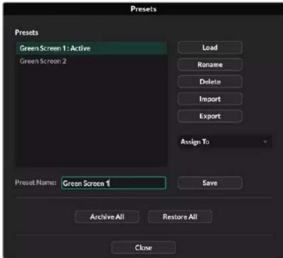
Oknno npedcytaHOBK B npnloKeHH Ultmatte Software Control
PopdkocoxpahenHn npedyctaHOBkn
1 Nocne Toro kak npouecopp Ultimatte noKIOUoyen K nCTOUYHK FOHa i CKOppeKTnpoBaHbI npaMeTpbi KOMN03HTnHra, ueKNHTe 3HaQOK paJNa, YTO6bI OTKpbITb OKHO npedyctaHOBok.
2 B none Preset Name BBeDnte IMa npEynctaHOBKn HAnKmTe KhONky Save.
3 CoxpaHennn npedyctaHOBka 6ydenOTO6paKaTbC B COOTBeTCTByIOUeM CINNCke.
Iopraok ydaeneHn npedyctaHOBKn
1 Bb6epnte B cncke coxpaehHHyIO npedyctahOBky, KOtopyIO HykHO ydaJIbTb.
2 Haxmte KhoNky Delete n noTBePnTe CBOB bIOp.
IopaoK 3aRpy3kn npedyctahOBKn
1 Bb6epnte B cncske coxpaHEnHyIO npedyCTaHOBky, KOtopyIO HyKHO 3arpy3nTb.
2 Haxmte KhoNky Load. Nocne 3arpy3kn npedyctaHOBKn prdom C ee IMeHem oTo6paXaTeTcA TeKT "Active File".
Popraok nepenMeHOBaHn npedyctaHOBKn
1 BbIepeRt B cncKcE coXpaHEnHyIO npedyctaHOBky, KOtopyIO HxKHO nepenMeHOBaTb. Ee TKyuee IIM dyET oTo6paxaTbcB noIe Preset Name.
2 B none Preset Name BBeDnte HOBOE mI npdyctaHOBKn. HaxmTe KhONky Rename.
Ha3haeHne npedyctaHOBOK
C NOMOJIIO FOYHKUIN Quick Preset MOXHO HA3HauNTb DO nIaTI INpeDyCTaHOBOK. 3TO NO3BOJAE6bICTPO B13bIBaTB INx C NOMOJIIO COOTBeTcTBByIOSe rMeHIO B npINOxKeHN Ultimatte Software Control INN pnoHymepoBaHHbIX KONOK HA MOneJAX CO BCTpoEHbIM XX-DnCnIeEM. OHn TaKke IOCTynbl IocpeDCTBOM KONOK QUICK LOAD Ha naHei Smart Remote 4.
Popraok Ha3nueHn npedyctaHOBKn Iy6bictporo Bbl0Ba
1 BbIepeHte HxKHyIO npedcyTaHOBky nCnCKa.
2 IcnoIb3yIte MeHIO Assign To, UTO6bl Ha3HaunTb npEynCTaHOBky dIg bIcTporo Bbl3OBA.
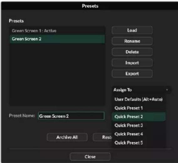
MeHIO Assign To no3B0n8T ha3hauatb npedyctahOBKn dna 6bIcIPO Bb3OBA
HmnpT n 3Kcnopt npedyctaHOBOK
Bce moen, 3a ncknoeHem Ultimatte 12, noepKBAOT mnpT nKcnpT npedyctahOBok. 3To no3BOJareT ekOHOMtB Bpem npn nCNoIb3ObaHH HeckoJIkX yCTpoiCTB Ultimatte, ecn Ha BCex n3 Hx Heo6xOIMO IMTe b OOnHaKOBbie napaMeTpbl KOMNO3HTIHra.
PopdoK ekcnopta npedyctahOBkn
1 Μεικητε θαγοκ παπκν B πριλοχευνι Λιμimatte Sfowware Control, ητόβι ΟΤΚρβΙΤΟΚΟ έπρεύγστα ΘΟΒΟΚ.
2 BbIepnTe B cncske coxpaHeHHyIO npedyctaHOBky, KOtOpyo HxHNO KcNopTupoBaTs.
3 Haxmte KhoNky Export n ykaxnre nyTb K cnucky coxpaHeHHbx npedyctaHOBOK. Haxmte Save.
Iopraok mnpota npedyctahOBK
1 OtkpoTe OKHO npedyctahOBok.
2 HaxmTe KhoNky Import.
3 B DnnaIorOBom OKHe npeiDnte K npedyctaHOBKe, KOtopyIO HxKHO NmnpTIpOBATe. HaxMnte Open.
4 NmnpTnpoBaHHa npedyctahOBka bdyet OToOpaxaTBcB CootBetCTByIOUeM CNICKe.
ApxNBbl
Apxnb npedctabnietcoobpeepBHyIO KOnIO Tekyuero cOCToHnI npoueccopa, Bcex erO hactpoek, npedyctahOBOK n codepxmoro MednaTeKN. Oh byet noJe3EN npi perylnpHOM nepekIooyen MExdy poeKTamn Cpa3bIMn TpeoBaHnMn I doabJIeHN B KOHfNpyauio donoJHntelhbx yctpoictb Ultimatte.
OdHH TOT Xe apxNB MoXHO nCnONb3OBaTb Ha pa3HbIX MoEJnx Ultimatte.
Cозданке apхива
EcnB npnnoxhen Ultimatte Software Control ueKHybMbIbHO Ha 3NaueKe nanko, MoXHo OTKpbTb OKHO npedyctaHOBOK n apxNBipOBAHNA.

1 Bn3y okHa npeducTaHOBok n apxnbupoBaHn HaxmTe KhoNky Archive All.
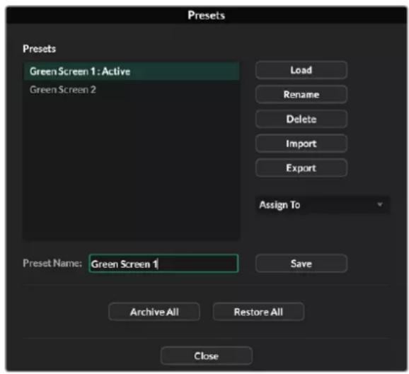
2 Ykaknte npTyK paIyu n BBeIte ero mHaXmTe Save.
Ppoecccop Ultimatte NaHHT co3aHHe apXnBa c HnDkauee BbIOnHeHHa 3aDaH.
No ee 3abepeHn npxNB oyTe oTo6paKaTbcra Ka k pai .zip Ha KOMnbIoTepe.
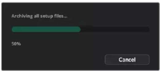
3arpy3ka apxnb
YTo6bI 3aRpy3nTb apxN, 5eJKNHTe MblbIO Ha 3HaueKe npKn B npInoxKeHH Ultimatte Software Control.
1 Bn3y OkHa npeducTaHOBOK n apxNbupoBaHn HaxMnte KOnky Restore All.

2 BДиалorobOM OKHe npeeInte K apxNBHomy paIIy, KOtOpbI HxKHO 3aRpy3NTb. HaxMnte Open.
3 Ppouecccop Ultimatte NaHcT 3aRpy3ky apxINBa C HnDnKaIeN BbInONHeHna 3aDaun.
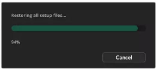
Ioo ee 3aBepseHn Ha Ultimatte 6dyT DocTyHb HAcTpOKn, npEynctaHOBKn, npaMeTpbl GPI nCTaunHbe N3o6paJehn MednateKn.
2 Ha BknaKe Options HaxmTe KhoNky Exit to Desktop.
3 Korda noBntcpaOch nTol, HaxMITE HaPpAeHHyIO BApex CTeKky B oBnactnyBvEdomleHm Windows.
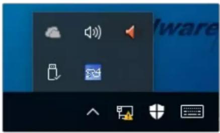
4 HaxMITE Ha 3aouk Ultimatte SR4 n ydepKuBaIte ero DBe cekyHbI. NpOBnTc3HaOKBbIXOJa. HaxMITE Ha Hero, YTO6bl 3akOHunb paOby C npInIOKeHNem.
Iopadok ydaenHn PO SR4 v1.1 nocneyuoux Hbpcn
1 Haxmte KhoNky Start Ha naHelen 3aayu BbIepePte Settings.
2 B OkHe HactpoeK mEHO BbIepePte System n nepeynTe K onuN Apps & Features.
3 B cnncke okna Apps & Features hainiTe IO Ultimatte SR4.
4 PpeiDnte K IO Ultimatte SR4 N BbIbepnTe Uninstall.
5 Cnedyte HNCTpykunm Ha 3KpaHe dny ydaenHna PO.
Порадok удалени ПО SR4 v1.0.5 и бoleп paHHnx Верси
1 Haxmte n ydepKuBaTe IoroTIn Windows B HxHem IeBOM yrny, 3aTeM BbIepeNTe «PpOBoDnK».
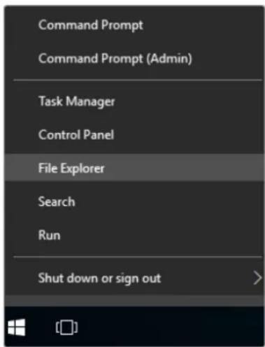
Haxmte HyepKbAite Iorotn Windows B neBOM HxHem yIy, 3aTe M Bi6peTne poBODHK
2 C nOmoIbIO npoBODnHa NaIte NaNky C:\Program Files\Ultimatte\SR4 nDbOIBm KacaHHeM 3aNyCTne npIoNoxHee maintenancetool.exe.
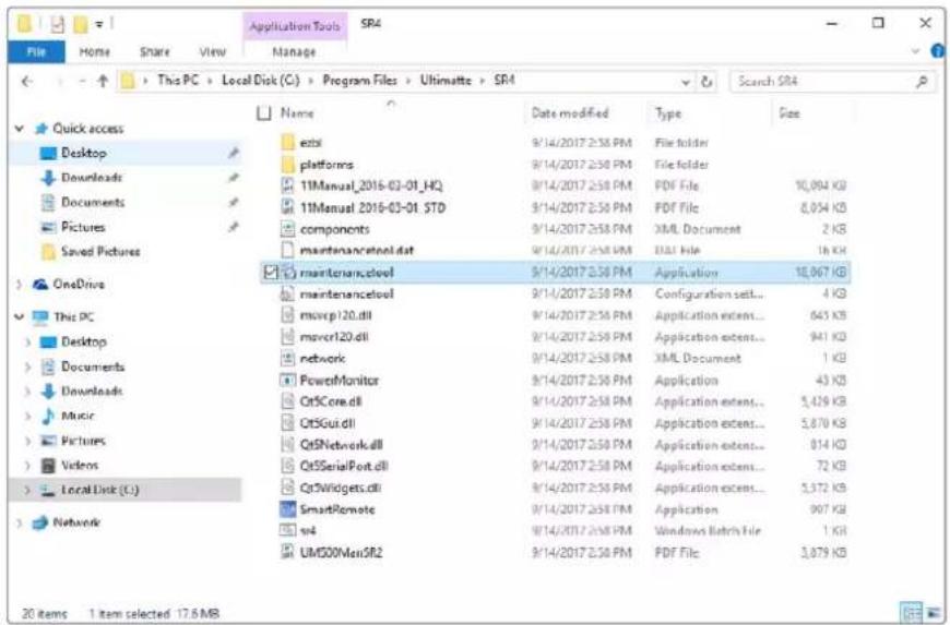
Ha dncke C nnonbanyte DBOHoe kacahne, yto6bl otKpbblnny
3 Bokhe npnloxehn Bb6epnte Remove all components n Haxmte Next.
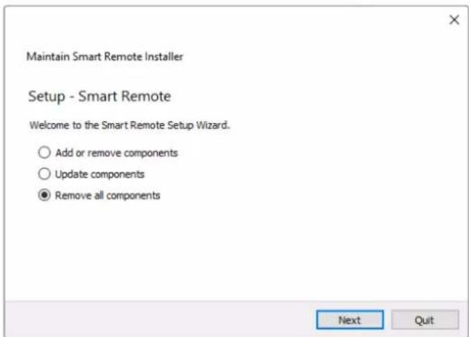
Bb6epnre Remove all components n Haxmnte Next.
4 T06bI BbINONHHT Heo6xOaMlbE DeiCTBn, HaxMtTe Uninstall, 3atem Yes.
5 BokHe Completing the Smart Remote Wizard HaxMITE Finish.
ПО дя naHEn ynpaBneHЯ Smart Remote 4 ydaneHo.
YctaHOBka yTnIITbI Ultimatte Smart Remote Setup
3arpynte nocneHIOB cepno ytnnbl Ultimatte Smart Remote Setup, kotopaa doctynha B pa3dene noedepkno no appecy www.blackmagicdesign.com/ru/support. Ckonnpyte qaiI .msi Ha cbeHbH Hocntel, HanpImep hakonntel USB.
Iopknouhte hakonntelb USB uepe3 cootbetctbyuoi npT cnepeHn ha naheN Smart Remote 4. Nocne ero aBtOMaTuueckoro paacnoHaabaHn OTKpoETc npOBdHk.
PIMMEAHNE. Cbemhbl HaKoNtEnb, c KOTOpO YoCTaHaBnBaEeTc npOrpaMMHoe oBeceueHne INaHeIynpaBHeHn, dOnJKeH 6bIb OTfOpMaTnpoBaH nI INcNoB3OBaHn KaK rIaBHa3 aRpy3OuHa3 aIInCb c OdHm pa3DeIom. Smrt Remote 4 noDepkNBAe T fOpMaTb NTFS, exFAT n FAT32.
Iopraok yctahOBKn nporpaMMHOro oecneueHn
1 Daxbl Haxmte Ha 3haoy cTahOBuNka IIO B nAnke Ha HakoNTe,
2 B MacTepe yctaHOBKuIeIKHnTe Next u cneNyTe HcTpyKUam Do eTana noJ Ha3BaHnEm Install.
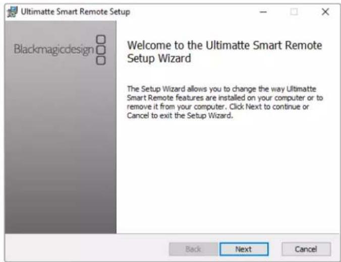
3 BbIepuTE Install, TToBbI BHeCTn Heo6xOaMlbE I3MeHEnH, 3aTeM Yes.
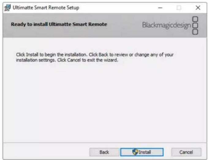
4 HaxmTe Finsh, yTo6bl 3aKoHHTb yCTaHOBky, 3aTeM Yes, YTO6bl nepe3anyctntb naHeIb Smart Remote 4.
Pocne 3Toro 6ydt BbInonHeH nobToPbH 3aynck naneN Smart Remote 4 c nocneHn Bepcnn nporpaMMHOrO oecneueHn.
5 Поветаядамогороь okHo Windows c npedIoXeHem yctaHOBHT CB3b c naheIbIO Smart Remote no cetn. BbIbePte onuio Private networks, such as my home or work network n HaxmTe KhONky Allow access.
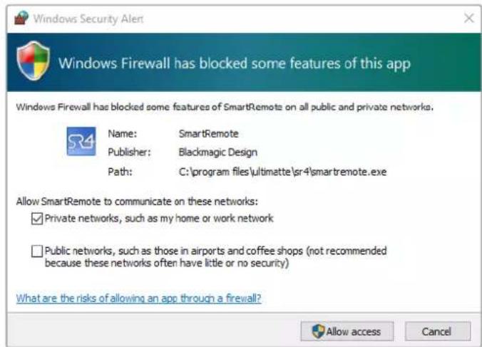
Iopknioyehne knaBnatapybIMbIuyepe3 npT USB
Ecn nIpaobToIc naHEnbIO Smart Remote 4 HxHo IcnoNb3ObaT KnaBnAtpy N MbIb, IN MoxKHO noKnouThpee3 npTb USB c TbIbHOn CTopoHb. OcbapyKeHe nepupeepnHbIX yCTpoiCTB n HacptoKa dIra paobToIc NK ha nnatpOpMe Windows 6yDyT BblonHeHb B aBTOMaTuueckom pexime.
YctaHOBka B cToiKy
MOnen Ultimatte 12 8K n Ultimatte 12 4K moXHO yCTaHOBuB B CToIky nn MObNbHbN Keic.
Jn3Toro noHaobntcneuaNBHykOMnNeKT Ultimatte.
Ecni npouecccop Ultimatte pa3meaioT ha cToIe, ero moxho ochactntb npinraeMbIMn pe3HHOBbIMn BCTabkAm. Ix kpenT K kaxdomy yrny Kopnyca 6e3 boknpobkn IMeOuixxCBHTOB.
KOMnIeKT dny yctahOBKn npouceccopa B cTOnky
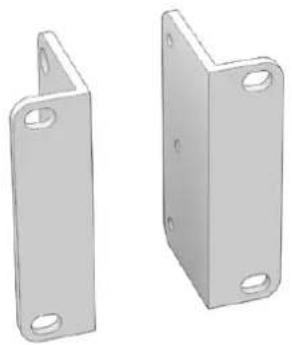
Дыпегднгскобь
PpeHnHaHeHbI DnYcTaHOBKn Ha BHeHnI nepeHnKpA yCToPoeCTBa.

DBe 3aHnE cKo6bI
PepdHa3HaueHbI dna yctaHOBKn Ha BHeuHn 3aHn KpaY cTpoNCTBa.

ДБЕnpokндяКорпуca
3Tn npoknaKMOxHO yCTaHOBnTB no
6OKAM KOpNyCa. OH npedHa3HauHeH bI
3aUHTb pa3bEmOB C TBbHOb CTopoHb,
a TaKke cIyXaT Ka BaxMbl IJI Ka6eJe,
NOkKnIOueHHbIX K yCTpoNCTBy.
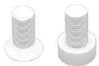
BnHTbI
12xM4 cytonneHHoI roIOBkoI
IepeDnXCKoB nPOKnAOKKOpYca
6xM4cnotaHnO rnoBko
Длэзднхскб
YctaHOBka nepeDnX cko6
NcnoB3yueeTnepaHHbI KIOU 2 MM nPnnaRaembe BHTbM4 cytonneHHoRTOOBKO, yctahOBte nepeHHe cKobicKaJdoCTopoHb yCTpoCTBa.
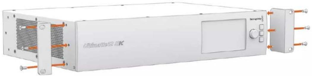
YCTaHOBka 3aDnHex cKo6
IcnoIb3yJwIeCTnIRpaHHBkIOU3MMNnpuNaRaEmbIe BnHTbIM4CnotaHOnrOOBKoYcTaHOBNTe 3aDHe NCKo6bHa Ultimatte 128K.
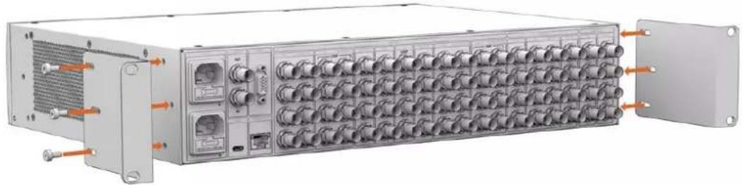
YcTaHOBka npOKnaDok Kopnyca
IcnoIb3y npinaraembe BnHbM4 cytonneHHo rONOBKo, yctaHOBte dOnonHtEnbHbI npoknKn dnn KOpnyca.
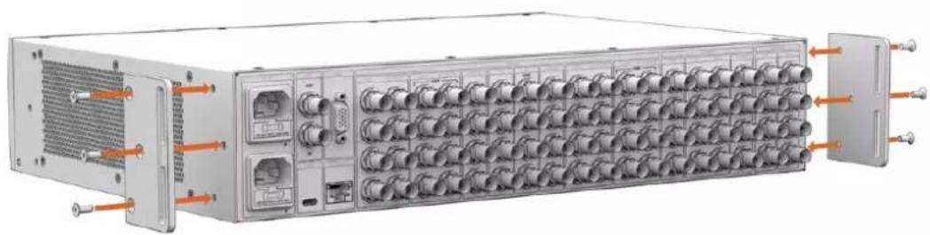
Размени в с Todке
Дя установиnpоцesscopob Ultimatte 12 HD Mini u Ultimatte 12 HD b ctoky nmoьньк keic ncoNb3yIOT noKy Teranex Mini Rack Shelf paMepom 1 RU.
Moden Ultimatte 12 HD Mini Ultimatte 12 HD hactoIbko MaIb, yTo Ix IerKo KOMbHnpoBaTc dpyroI texHkoB Blackmagic Design, kOtopa nMeet aHaonuHbI pOpM-kaTOp (B TOM cncLe konBeptepb Teranex Mini, peSeHnra MultiView 4 n Web Presenter). HApPIMeP, npN nCnoB3ObaHn npouecoppa Ultimatte 12 HD Mini c pekopdepom HyperDeck Studio HD Mini moXHO Bectn zanncb npOrpaMMHoro notoka nn CnHana MOHtOpHra. TaKo MOnyIbHbI dIzaiN no3BOJareT co3DaBaTb nopTaTHBHe i npocTbe KOHfNguraun NOD INHINBHyaJIbHbIte TpeOBaHn.
KoMnJIeKT Teranex Mini Rack Shelf Kit
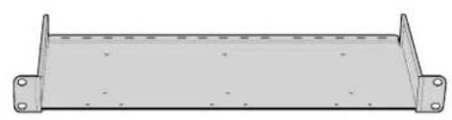
Onda noka Teranex Mini Rack Shelf
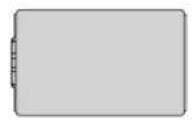
Onda 3aInyuka 1/6 RU
IcnoB3yeTc npn pa3meHn peHn c fOpm-
fakTopoM 1/2 RU b KOM6HaCn C yctpoiCTBOM
uipinHO1/3 RU nnn 3aargykoN.
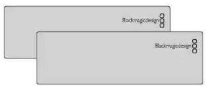
ДыЗаглушкN 1/3RU
NcnoB3yioTc nra 3aonHHeHH nyctoro npocpaHCTBa npn paMeueHn Ondoro yctpoHCTBa.

BnHTbI
8×M3(5MM)
2×M3(10MM)
BnhtbcytonneHHo
PnockneBHTbIa
TOLOBKoi
Zarnywek 1/6 RU
Iopraok yctahOBk moJeul Ultimatte 12 HD Mini uUltimatte 12 HD
1IpepaMaMeuHemIIObOyCTBaHa nonKe Teranex Mini Rack Shelf Heo6xOIMO CHaTb erOp pe3HOBBIE BCTABKN.
2 Npebeephyb nonky u yctpoicBO, BblpoBnHte nx no TOTOBIM MOHTaXHBIM OTBepCTNm. Ha pewehna x c opm-paKTopoM 1/3 RU ux Dba, n OHn paCnoNoxKeHb no ceHTpy, a Ha 6onee kpynhbx yctpoiCTbax (Hanpumep, HyperDeck Studio HD Plus) taKnx OTBepCTn TPN. Nx pacnoNoxKeHne 3abucnt OT TORO, C kaKo CTopoHb nonKn BblonHnEETcYCTaHOBka.
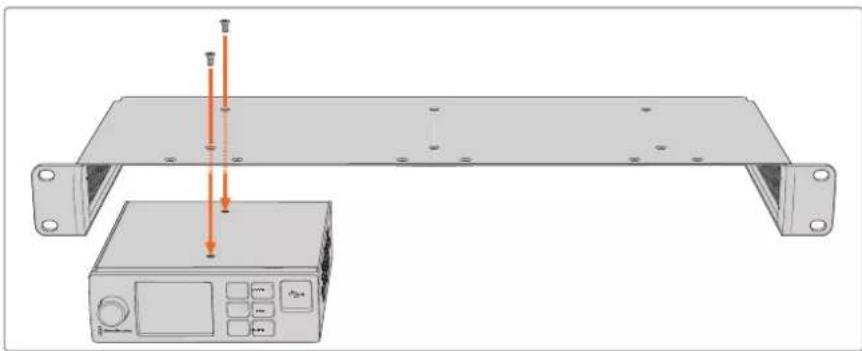
3 IcnoIb3y npinaraemble 5-MM BnHTbM3 cytonneHHo rnoBko, zakpenite yctpoiCTBO Ha noJIke.
4 Nocne yctaHOBKn peKOpDepa HyperDeck nIu DpyrOo peWEnHn Blackmagic nepeBepHnTe noIky B HopMaIbHoe noLoXeHnE nNoMeCTnTe ee B cTouKy.
3aRnyuKMOxHNOcNoB3oBaTbIyIaONHeHnIpyCTOro npoctpaHCTBa, Hapmep npNyctanOBke pekopdepa HyperDeck Studio HD Mini cpewHnem Blackmagic Web Presenter.
Iopadok yctahOBkn 3aynuikn 1/6 RU
3arnyuka 1/6 RU npedHa3aHae enIncnoB3oBaHn c yctpoiCTbAmn fopm-faktopa 1/2 RU (hapnpimep, HyperDeck Studio HD Plus), korda nX yctaHabnBaIOT OTeJIbHO nIc npOdykTAMn shinpoh 1/3 RU, takumn ka Blackmagic Web Presenter. 3arnyuKy paMaEuaIOT c60ky ot yctpoiCTBa no HnpabneHIO K ceHTpy cToiKN, YTObI oecneuHTb cIrpKyIauNIO BO3dyxa.
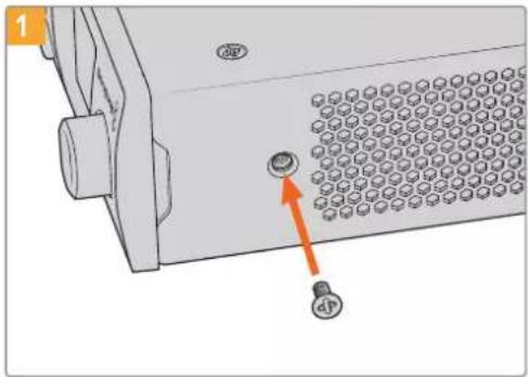
N3BnKeNTe5-MMBHTM3c60ky ot npedneHnaHnn yctpoNCTBa
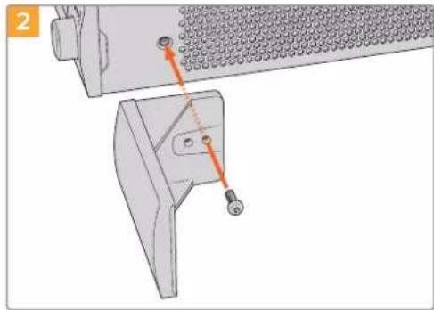
BbpoBnIte 3aIyUky n 3akpenite ee c nmoIbIO npnilaraemoro 10-MM BHTa M3
Iopraok yctahOBkn 3aflnyuKn 1/3RU
Cobmctte otBepnno Bnhty npokny toky c noKo. 3aRnyk y 1/3 RU moxho pa3meaTb c IIO60I CTOPHO nI NO CEHTpy noKu. IcnoIb3yra DBA 5-MM BnHt a M3 cytonHeHHo rOIOBko, 3akpenTe 3aRnyk.
Дя устюпсв с велоченногглбног (hanpimep, Blackmagic Studio Converter) nCnoIb3yTe nonky Blackmagic Universal Rack Shelf.
Developer Information
Controlling Ultimatte using Telnet
The Blackmagic Ultimatte 12 Ethernet Protocol gives you the freedom to build your own custom control solutions for your Ultimatte 12. For example, you can create your own software application and control your Ultimatte via Ethernet from your computer.
The first step is to connect your Ultimatte to your computer via Ethernet. You can do this by connecting Ultimatte to the same network your computer is connected to, or you can connect Ultimatte directly to your computer.
NOTE If your Blackmagic Ultimatte is connected directly to your computer, set your computer to a manual static IP address. Set the first three blocks of numbers in the IP address to match your Ultimatte and set the subnet mask to 255.255.255.0. You can leave the gateway or router setting blank as it will not be used in a direct connection between your computer and Ultimatte.
If your network settings are set correctly, you can now open the Terminal application on Mac OS, or enable Telnet command line utilities on Windows and enter Ultimatte control protocol commands. These commands can be programmed into your application and triggered by related items on a custom user interface of your own design.
Below is a basic example of using Telnet to change the backing color, restore to factory defaults, and adjust the matte density control.
1 In the Terminal application, type the following:
telnet (IP address of main unit (space) port number)(enter)
For example: telnet 192.168.10.220 9998
Press 'enter'.
A list of status information will appear and you are ready to control your Ultimatte.
2 Now type the following:
control: (press enter)
backing color: blue (press enter twice)
Terminal will acknowledge the action with 'ack' and confirm it so you know your setting has been performed.
You have now changed Ultimatte's backing color to blue.
3 To restore to factory defaults, type the following:
control: (press enter)
factory defaults: yes (press enter twice)
This restores your Ultimatte to factory default settings and performs an automatic composite.
4 To adjust the matte density setting, type the following:
control: (press enter)
matte density: 273 (press enter twice)
Terminal will acknowledge and confirm the action.
You have now adjusted the matte density setting.
5 To exit Telnet
Hold down the control button and press the 'J' key. The Telnet prompt will appear.
Type the following:
quit press enter)
A status message will appear confirming the connection is closed.
Blackmagic Ultimatte 12 Ethernet Protocol
Version 2.0
If you are a software developer you can use Ultimatte Ethernet Protocol to construct devices that integrate with our products. Here at Blackmagic Design our approach is to open up our protocols and we eagerly look forward to seeing what you come up with!
Overview
The Blackmagic Ultimatte Ethernet Protocol is a text based protocol that is accessed by connecting to TCP port 9998 on an Ultimatte.
Ultimatte sends information in blocks. Each block has an identifying header in all caps, followed by a full colon. A block spans multiple lines and is terminated by a blank line. Each line in the protocol is terminated by a newline character.
Upon connection, the Ultimatte device sends a complete update of its status. After the initial status transmission, status updates are sent every time the Ultimatte device's status changes.
To be resilient to future protocol changes, clients should ignore blocks they do not recognize, up to the trailing blank line. Within existing blocks, clients should ignore lines that they do not recognize.
Protocol Preamble
The first block sent by Ultimatte is always the protocol preamble:
PROTOCOL PREAMBLE: Version: 2.0
The version field indicates the protocol version. When the protocol is changed in a backwards compatible way, the minor version number will be updated. If incompatible changes are made, the major version number will be updated.
Identity
The next block contains information about the device identity.
ID EN T IY:
Model: Ultimatte 12 8K
Label: Ultimatte 12 8K
Unique ID: 12345678
Network Information
There are two network blocks. The first describes the general network information and the second describes the network interface details.
NETWORK: Interface count: 1 Default Interface: 0 Static DNS Ser vers: 8.8.8.8, 8.8.4.4 Current DNS Ser vers: 8.8.8.8, 8.8.4.4
NETWORK INTERFACE 0:
Name: Cadence GigE Ethernet MAC
Priority: 0
MAC Address: xx.xx.xx.xx.xx.xx
Dynam icIP: false
Cu rre nt A d d re s e s: 10.0.0.2/255.255.255.0
Cu rre nt G ate way: 10.0.0←1
Static A dd resses: 10.0.0.2/255.255.255.0
Static Gate w ay: 10.0.0.1←1
Version Information
The version information describes the hardware and software version numbers and identifiers of the device. For example, the "Product ID" field contains the hexadecimal USB Product Identifier.
VERSION: Product ID: BE84 Hardware Version: 0100 Software Version: 09A89B7 Software Release: 2.0
Device Information
The next block contains general information about the connected Ultimatte device.
NOTE Some Ultimatte models will only have a subset of the above-mentioned inputs.
For example, the Ultimatte 12 HD Mini only has the following inputs:
- Foreground input (FG In), and
Background input (BG In).
Similarly, the Ultimatte 12 HD only has the following inputs:
- Foreground input (FG In),
Background input (BG In),
Garbage Matte input (G MATTE In),
Holdout Matte input (H MATTE In),
Monitor Input (MONITOR In), and
Reference Input (REF In).
Video Formats Information
The Video Formats blocks lists the video formats supported by the device. See the Video Format Control list to find the formats supported by each device.
VIDEO FORMATS: auto detect 525.59.94 NTS C 4:3625i50 PAL 4:3720p60
…
Initial Status Dump
The next eleven blocks provide the control values, control default values, current file, file list, the GPI lists, the Frame Buffer Image List and Frame Buffer State.
CONTROL:
Matte Density: 0
Red Density: 0
Green Density: 0
...(Full list in Controls section)
<sup>+</sup>
CONTROL DEFAULT LT:
Matte Density: 0
Red Density: 0
Green Density: 0
...(Full list in Controls section)
<sup>+</sup>
CUR R ENT FILE
Filename <sup>+</sup>
<sup>+</sup>
FILE LIST:
File 1
File 2
<sup>+</sup>
GPI LIST:
ID: 1
Index: 0
File 1
File 2
NOTE The Ultimatte 12 HD Mini does not have GPI inputs, so this block is not available on that device.
The IMAGE LIST block contains the filenames of images that are currently stored on the device. These images can be assigned to Frame Buffer inputs.
IM AGE LIST:
Image 1
Image 2
The FRAME BUFFER block contains the status of the Frame Buffers on the device.
This information will show:
How many image buffers are available,
- whether a frame buffer is enabled and has an image buffer assigned to it, and
- how frame buffer transitions are set up for those frame buffers that support transitions.
NOTE Frame Buffer Duration time is in milliseconds.
FRAME BUFFER: Number Of Frame Buffers: 46 BG 1 Frame Buffer Enable: off BG 1 Frame Buffer Index: 0 LY 1 Frame Buffer Enable: off LY 1 Frame Buffer Index: 0 BG 2 Frame Buffer Enable: off BG 2 Frame Buffer Index: 0 LY 2 Frame Buffer Enable: off LY 2 Frame Buffer Index: 0 GM Frame Buffer Enable: off GM Frame Buffer Index: 0 HM Frame Buffer Enable: off HM Frame Buffer Index: 0 BG Frame Buffer Mix: 0 LY Frame Buffer Mix: 0 BG Transition Duration: 0 LY Transition Duration: 0 Frame Buffer 1: Image 1 Frame Buffer 2: Image 2 ...
End Prelude
The final block of the status dump sent by Ultimatte is always end prelude:
END PRELUDE:
Status Updates
When any Control is changed on an Ultimatte device, the Ultimatte device replies with the applicable status block to all connected clients, containing only the items that have changed. For example, if Matte Density has been changed, the following block will be sent:
CONTROL: Matte Density: 0
If multiple items are changed, multiple items may be present in the update:
CONTROL: Matte Density: 0 Red Density: 0
These notifications are sent whether the change originated from the front panel, or from any other connected client.
Requesting Changes
To update a Control the client should send a block of the same form Ultimatte sends when its status changes. For example, to change Matte Density to 100, the client should send the following block:
CONTROL: Matte Density: 100
The block must be terminated by a blank line. On receipt of a blank line, Ultimatte will either acknowledge the request by responding:
ACK←
←
or indicate that the request was not understood by responding:
NAK
After a positive response, the client should expect to see a status update from Ultimatte showing the status change. This is likely to be the same as the command that was sent, but if the request could not be performed, or other changes were made simultaneously by other clients, there may be more updates in the block, or more blocks. Simultaneous updates could cancel each other out, leading to a response that is different to that expected.
In the absence of simultaneous updates, a simple control change will result in the following protocol exchange:
CONTROL:
Matte Density: 0 ACK
CONTROLC:
Matte Density: 0
The asynchronous nature of the responses means that a client should never rely on the desired update actually occurring and must simply watch for status updates from Ultimatte and use only these to update its local representation of Ultimatte's state.
A client may also request Ultimatte to change a control by a relative amount. For example, to change Matte Density by 10, the client should send the following block:
CONTROL:
Offset Matte Density: 10
Only controls with numerical ranges support this relative mode.
Requesting a Status Dump
The client may request that Ultimatte resend the complete state of any status block by sending the header of the block, followed by a blank line. In the following example, the client requests Ultimatte resend the control status:
CONTROL: ACK
CONTROL:
Matte Density: 0
Red Density: 0
Green Density: 0
... (Full list in Controls section)
File System
The client may request that Ultimatte load, save, delete, or rename a file. To load a file the client should send the following block:
FILE:
Load:
Ultimatte will respond with an ACK followed by a Current File block or a Message block.
To save, delete, or rename a file the client should send one of the following blocks:
FILE:
Save: <filename>
<
FILE:
Delete: <filename>
<
FILE:
Rename: <filename>
To: <filena me>
<
In each case Ultimatte will respond with an ACK followed by a File List block or a Message block.
GPI Event List
The client may request that Ultimatte add, insert or remove an event to a GPI Event List by sending an Insert GPI Event or Remove GPI Event command, followed by a blank line.
For example, to insert an event, the client should send the following block:
GPI:
ID: 1
Insert: <filename>
At: -1 {The insertion index. A '-1' represents the end of the list}
To remove an event a client would send the following block:
GPI:
ID: 1
Remove: 1 ← {Event index to remove. A '0' will delete all events}
To set the current event index a client would send the following block:
GPI: ID: 1 Index: 1
Ultimatte will respond with an ACK message followed by either a GPI List Block or a Message Block.
GPI LIST:
ID: 1
Index: 0
File 1
File 2
...
or
MESSAGE:
Warning: Event limit exceeded
Frame Buffer
The client may request that the Ultimatte device assign a pre-loaded image from its Media Pool into a particular frame buffer and enable/disable the frame buffer. To assign and enable an image to the BG frame buffer the following commands are required:
FRAME BUFFER:←
BG 1 Frame Buffer Index: 1 BG 1 Frame Buffer Enable: on-
To disable the frame buffer only the enable command is required:
FRAME BUFFER: BG1FrameBufferEnable:on
NOTE The Telnet interface does not currently provide loading or removing images in the Media Pool. This has to be done from either a Smart Remote 4, or using the Software Control application. Refer to the 'using the media pool' section of this manual for more information.
Camera Control
Ultimatte 12 HD Mini can be used to control an attached camera via SDI or HDMI, please refer to the 'Camera Control via Ultimatte 12 HD Mini' section for more information. For SDI Camera Control, the Ultimatte device's Camera ID may be changed using the CAMERACONTROL block:
CAMERACONTROI CameraId:1\~
NOTE This control block is only available on the Ultimatte 12 HD Mini.
Controls
| Matte Density 0-10000 | |
| Black Gloss 0-10000 | |
| Blue Density 0-10000 | |
| Green Density 0-10000 | |
| Red Density 0-10000 | |
| Shadow Level 0-10000 | |
| Shadow Threshold 0-10000 | |
| Matte Correct Horizontal Size 0-6 | |
| Matte Correct Vertical Size 0-3 | |
| Cursor X 0-10000 | |
| Cursor Y 0-10000 | |
| Cursor 2 X 0-10000 | |
| Cursor 2 Y 0-10000 | |
| Vell Master 0-10000 | |
| Vell Red 0-10000 | |
| Vell Green 0-10000 | |
| Vell Blue 0-10000 | |
| Vell Correct Horizontal Size | 0-6 |
| Vell Correct Vertical Size | 0-6! |
| Wall Color Red | 0-10000 |
| Wall Color Green | 0-10000 |
| Wall Color Blue | 0-10000 |
| Floor Color Red | 0-10000 |
| Floor Color Green | 0-10000 |
| Floor Color Blue | 0-10000 |
| Cleanup Level 0-10000 | |
| Cleanup Dark Recover | 0-10000 |
| Cleanup Light Recover | 0-10000 |
| Cleanup Strength | 0-10000 |
| GM Cleanup Level | 0-10000 |
| GM Cleanup Dark Recover | 0-10000 |
| GM Cleanup Light Recover | 0-10000 |
| GM Cleanup Strength | 0-10000 |
| Correction Level | 0-10000 |
| Noise Level | 0-10000 |
| Black Balance 0-10000 | |
| Gray Balance | 0-10000 |
| Controls | |
| White Balance 0-10000 | |
| Flare Level 0-10000 | |
| Cool 0-10000 | |
| Skin Tone 0-10000 | |
| Light Warm 0-10000 | |
| Dark Warm 0-10000 | |
| Flare Correct Horizontal Size 0-6 | |
| Flare Correct Vertical Size 0-6 | 1 |
| Ambiance Master 0-10000 | |
| Ambiance Red 0-10000 | |
| Ambiance Green 0-10000 | |
| Ambiance Blue 0-10000 | |
| Ambiance Strength 0-10000 | |
| Direct Light Red | 0-10000 |
| Direct Light Green | 0-10000 |
| Direct Light Blue | 0-10000 |
| Direct Light Mix | 0-10000 |
| Vertical Blur | 0-10000 |
| FG Saturation Red | 0-10000 |
| FG Saturation Green | 0-10000 |
| FG Saturation Blue | 0-10000 |
| FG Saturation Master | 0-10000 |
| FG Contrast Red | 0-10000 |
| FG Contrast Green | 0-10000 |
| FG Contrast Blue | 0-10000 |
| FG Contrast Master | 0-10000 |
| FG Black Red | 0-10000 |
| FG Black Green | 0-10000 |
| FG Black Blue | 0-10000 |
| FG Black Master | 0-10000 |
| FG White Red | 0-10000 |
| FG White Green | 0-10000 |
| FG White Blue | 0-10000 |
| FG White Master | 0-10000 |
| FG Contrast Crossover | 0-10000 |
| Fade Mix | 0-10000 |
| BG Saturation Red | 0-10000 |
| BG Saturation Green 0-10000 | |
| BG Saturation Blue 0-10000 | |
| BG Saturation Master 0-10000 | |
| BG Contrast Red 0-10000 | |
| BG Contrast Green 0-10000 | |
| BG Contrast Blue 0-10000 | |
| BG Contrast Master 0-10000 | |
| BG Black Red 0-10000 | |
| BG Black Green 0-10000 | |
| BG Black Blue 0-10000 | |
| BG Black Master 0-10000 | |
| BG White Red 0-10000 | |
| BG White Green 0-10000 | |
| BG White Blue 0-10000 | |
| BG White Master 0-10000 | |
| BG Contrast Crossover 0-10000 | |
| BG Filter 0-10000 | |
| Test Signal Master | 0-10000 |
| Test Signal Red | 0-10000 |
| Test Signal Green | 0-10000 |
| Test Signal Blue | 0-10000 |
| LY Saturation Red | 0-10000 |
| LY Saturation Green | 0-10000 |
| LY Saturation Blue | 0-10000 |
| LY Saturation Master 0-10000 | |
| LY Contrast Red | 0-10000 |
| LY Contrast Green | 0-10000 |
| LY Contrast Blue | 0-10000 |
| LY Contrast Master 0-10000 | |
| LY Black Red | 0-10000 |
| LY Black Green | 0-10000 |
| LY Black Blue | 0-10000 |
| LY Black Master | 0-10000 |
| LY White Red | 0-10000 |
| LY White Green | 0-10000 |
| LY White Blue | 0-10000 |
| LY White Master | 0-10000 |
| LY Contrast Crossover 0-10000 | |
| LY Filter 0-10000 | |
| LY Test Signal Master 0-10000 | |
| LY Test Signal Red 0-10000 | |
| LY Test Signal Green 0-10000 | |
| LY Test Signal Blue 0-10000 | |
| LY Fade Mix 0-10000 | |
| Lighting Level Red 0-10000 | |
| Lighting Level Green 0-10000 | |
| Lighting Level Blue 0-10000 | |
| Lighting Level Master 0-10000 | |
| Lighting Minimum Level 0-10000 | |
| Window Position Top 0-(Based on Video Format) | |
| Window Position Bottom 0-(Based on Video Format) | |
| Window Position Left 0-(Based on Video Format) | |
| Window Position Right 0-(Based on Video Format) | |
| Window Softness Top 0-10000 | |
| Window Softness Bottom | 0-10000 |
| Window Softness Left 0-10000 | |
| Window Softness Right | 0-10000 |
| Window Skew Top 0-10000 | |
| Window Skew Bottom | 0-10000 |
| Window Skew Left | 0-10000 |
| Window Skew Right | 0-10000 |
| Window Skew Offset Top | 0-10000 |
| Window Skew Offset Bottom | 0-10000 |
| Window Skew Offset Left | 0-10000 |
| Window Skew Offset Right | 0-10000 |
| Transition Rate | 1-120 |
| BM Process Horizontal | 0-3 |
| BM Process Vertical | 0-3 |
| BM Filter | 0-10000 |
| BM Input Level | 0-10000 |
| BM Input Offset | 0-10000 |
| GM Process Horizontal | 0-3 |
| GM Process Vertical | 0-3 |
| GM Filter | 0-10000 |
| GM Input Level 0-10000 | |
| GM Input Offset 0-10000 | |
| HM Process Horizontal 0-3 | |
| HM Process Vertical 0-3 | |
| HM Filter 0-10000 | |
| HM Input Level 0-10000 | |
| HM Input Offset 0-10000 | |
| LM Process Horizontal 0-3 | |
| LM Process Vertical 0-3 | |
| LM Filter 0-10000 | |
| LM Input Level 0-10000 | |
| LM Input Offset 0-10000 | |
| Noise Cursor X 0-10000 | |
| Noise Cursor Y 0-10000 | |
| FG Input Frame Delay 0-14 | |
| FG Input U Position 0-10000 | |
| FG Input V Position | 0-10000 |
| FG Input UV Position | 0-10000 |
| Talent Highlight Level** | 0-10000 |
| Monitor Highlight Level | 0-10000 |
| Matte Out Level 0-10000 | |
| Output Offset | -1500-+1500 |
| GP Out Delay* | 1-120 |
| GP1 Input Delay* | 1-120 |
| GP2 Input Delay* | 1-120 |
| GP3 Input Delay* | 1-120 |
| GP4 Input Delay* | 1-120 |
| GP5 Input Delay* | 1-120 |
| Matte Enable | On/Off |
| Screen Correct On/Off | |
| GM Cleanup Enable | On/Off |
| Noise Enable | On/Off |
| Noise Cursor Enable | On/Off |
| FG Freeze | On/Off |
| FG Advanced Contrast Enable | On/Off |
| Advanced Flare Enable | On/Off |
| HM Flare Enable | On/Off |
| Ambiance Enable On/Off | |
| BG Gradient Enable On/Off | |
| BG Freeze On/Off | |
| BG Advanced Contrast Enable On/Off | |
| BG Test Signal Enable On/Off | |
| LY Input Enable On/Off | |
| LY Advanced Contrast Enable On/Off | |
| LY Freeze* On/Off | |
| LY Test Signal Enable On/Off | |
| Lighting Enable On/Off | |
| Window Enable On/Off | |
| Window BM Enable On/Off | |
| Window GM Enable | On/Off |
| Window HM Enable | On/Off |
| Window LM Enable | On/Off |
| Window Invert | On/Off |
| Wall Cursor Position Enable | On/Off |
| Floor Cursor Position Enable | On/Off |
| Dual Cursor | On/Off |
| Manual Color Enable | On/Off |
| Custom Powerup(deprecated) | On/Off |
| BM Enable | On/Off |
| BM Invert | On/Off |
| BM Process Invert | On/Off |
| BM Freeze** | On/Off |
| GM Enable | On/Off |
| GM Invert | On/Off |
| GM Process Invert | On/Off |
| GM Freeze* | On/Off |
| HM Enable | On/Off |
| HM Invert | On/Off |
| HM Process Invert | On/Off |
| HM Freeze* | On/Off |
| LM Invert | On/Off |
| LM Process Invert | On/Off |
| Monitor To Program | On/Off |
| Monitor To Talent** | On/Off |
Controls
| Fill Linear Mix Correction* On/Off | |
| Talent Mirror** On/Off | |
| Monitor Cascade On/Off | |
| Matte Out Invert* On/Off | |
| On Air Enable On/Off | |
| On Air Lockout On/Off | |
| Matte View Range On/Off | |
| Matte View Invert On/Off | |
| Monitor Out RGB On/Off | |
| Monitor Out Red Only On/Off | |
| Monitor Out Green Only On/Off | |
| Monitor Out Blue Only On/Off | |
| GP Out Save* On/Off | |
| Quickload 1 | On/Off |
| Quickload 2 | On/Off |
| Quickload 3 | On/Off |
| Quickload 4 | On/Off |
| Quickload 5 | On/Off |
| Quicksave 1 | On/Off |
| Quicksave 2 | On/Off |
| Quicksave 3 | On/Off |
| Quicksave 4 | On/Off |
| Quicksave 5 | On/Off |
| GP 1 Input Enable* On/Off | |
| GP 2 Input Enable* | On/Off |
| GP 3 Input Enable* | On/Off |
| GP 4 Input Enable* | On/Off |
| GP 5 Input Enable* | On/Off |
| GP 1 High Enable* | On/Off |
| GP 2 High Enable* | On/Off |
| GP 3 High Enable* On/Off | |
| GP 4 High Enable* On/Off | |
| GP 5 High Enable* | On/Off |
| Tally Active | On/Off (Read Only) |
| 3G SDI level | A/B |
| Color Space* | Rec.709/Rec.2020 |
| Filter Mode | Median/Average |
| Controls | |
| Filter Median 0/1/2/3/4 | |
| Filter Average 0/1/2/3/4 | |
| LY In Mix Mode Realistic/Linear/Additive | |
| Backing Color Red/Green/Blue | |
| Cursor Position Default/Last | |
| GP Out Level" High/Low | |
| Output Range Normal/Full | 2 |
| Monitor Out Program, FG, BG, Combined | Matte, Internal Matte, Fill, Layer In, Background Matte In, Garbage Matte In, Holdout Matte In, Layer Matte In, Processed LM, Processed HM, Processed GM, Processed BM, Screen Correction |
| Layer Order FG/Layer/BG Layer/BG, Layer/FG/ | BG Layer/BG, Layer/BG Layer/FG/BG, BG Layer/Layer/FG/BG, BG Layer/FG/ |
| Layer/BG, FG/BG Layer/Layer/BG, FG/BG Layer/BG, BG Layer/FG/BG, FG/Layer/BG, Layer/FG/BG | |
| Video Format Auto Detect, 525i59.94 NTSC 4:3, | 625i50 PAL 4:3, 720p60, 720p59.94, 720p50, 1080i60, 1080i59.94, 1080i50, 1080p60, 1080p59.94, 1080p50, 1080p30, 1080p29.97, 1080p25, 1080p24, 1080p23.98, 1080PsF30, 1080PsF29.97, 1080PsF25, 1080PsF24, 1080PsF23.98, 2160p60, 2160p59.94, 2160p50, 2160p30, 2160p29.97, 2160p25, 2160p24, 2160p23.98, 4320p60, 4320p59.94, 4320p50, 4320p30, 4320p29.97, 4320p25, 4320p24 and 4320p23.984 |
| Factory Defaults Yes | 5 |
| User Defaults Yes | 5 |
| Auto Screen Sample Yes | 5 |
| Screen Capture Yes | 5 |
| Noise Select | Yes5 |
| Sample Wall | Yes5 |
| Sample Floor | Yes5 |
| Matte Reset Yes | 5 |
| Cleanup Reset | Yes5 |
| GM Cleanup Reset | Yes5 |
| FG Color Reset | Yes5 |
| BG Color Reset Yes | 5 |
| Flare Reset | Yes5 |
| Ambiance Reset Yes | 5 |
| BG Test Signal Color Reset Yes | 5 |
| LY Color Reset Yes | 5 |
| LY Test Signal Color Reset Yes | 5 |
| Window Reset Yes | 5 |
| Window Skew Reset Yes | 5 |
| GP Out* Yes | 5 |
1 These ranges are Ultimatte device dependent. For Ultimate 12 8K running protocol 2.0, the range is 0-6. For Ultimatte 12 running version 1.2, the range is 0-3.
2 These controls are only available in protocol version 2.0 and up.
3 Loop outputs for 'garbage matte' and 'holdout matte' inputs are available for Ultimatte 12, not Ultimatte 12 8K.
4 Supported video formats are Ultimatte device dependent. 4320p formats are available for Ultimatte 12 8K. Ultimatte 12 HD Mini does not support PsF video formats.
5 These controls represent functions. Send 'Yes' to execute the function. Ultimatte will respond with a 'Yes' to indicate the function is complete.
These controls are not available on the Ultimatte 12 HD Mini
These controls are not available of the Ultimatte 12 HD or HD Mini
| Glossary | |
| FG | Foreground |
| BG | Background |
| LY | Layer |
| GM | Garbage Matte |
| BM | Background Matte |
| HM | Holdout Matte |
| LM | Layer Matte |
Pomoucb
Kak noyuHTb nOmoa
Cama 6bCTpbn cnooc noIyUHTb nOmoa - opaTntcKa n CtpaHuaam noIepKHa caTe Blackmagic Design n npOBepNTb HAIuue nocleDnX cnpaBOUYbx MaepnaNoB no Blackmagic Ultimatte nn Smart Remote 4.
CtpaHnUbI noDpeKKn Ha caTe Blackmagic Design
PocneHne BepcnnypkoBOnCTBa no 3cKnpyataun nporpaMmHoro oecneueHHa taKke DonoHnTeIbHyIO INΦopMaUIO MOxHO hain T B ceHTpe noDaeppKKn BlaCmigc Design Ha cTpaHnce www.blackmagicdesign.com/ru/support.
DonyckaetcaKcnnyataunB MeCTax He BbIe 2000 MetpoB HaI yPOBHeM MOpA.
PpeDynpexdEneIe IxHnueckoro nepcohaIa

IpepeoocnykBaHneOKnIOUHTe NHTaHHe HaoboxCNIOBbIX pa3beMax.

Octopoxho: nlabkn npedoxpahnteB DByxnoIOCHbI/B HeHTpaII
BLOK NITaHIN B 3TOM yCTPOIcTBe IMeET ppeOxApaHInTeJIb B JINHeHOM H HeITpAlbHOM npOBoDax IN NOxODNT IIN PNOKLIQUeHIN K CnCTeMe 3HepronitAHIN TtNa IT B HopBerIn.
Гаранта
OrpaHnueHHa rapaHTnA cPOKom 12 mecaeB
KomnaHnra Blackmagic Design rapaHTnpyET OTCYCTBVE B daHHOM n3eJInn DepeKTOB MaTePnana n npOn3BOcTBeHHoro 6paKa B TeueHne 12 MecaeB C DaTb IpOdaXn. EcnB BO BpeMra rapaHTnHoro cpoKa 6dyT BbIbHebl DepeKtbl, Blackmagic Design no CBOemy yCMOTpeHIO BBINOHNr peMOHT HeNCnpaBHoro n3eJn8 6e3 ONNaTbI CTOnMOCTn 3aNCAteN IN Tpydo3aTpA Tnn 3aMeHNT TaKoe n3eJIne HOBbIM.
YTo6bI BocnoJIb3OBAIbC HAcTcHaeI rapaHTne, noTp6bIeNb 6o3aH yBeDMITb KOMnHaIO Blackmagic Design o depeKTe do OKOHuaHra rapAHTnHO rpoKa n OecneuHTy cNoBn dJa npedocTabHeHn Heo6xOaMbIX ycnyr. NpTe6bIeNb Hecet OTBETCTBEHHOCt b3a yNaKOBky IdoCTABky HeNCnPabHorO n3dEInB B COOTBETCTByIOUm CepBucnbl CEHTP Blackmagic Design c OnlatoN noTOBbIX paXoOB. NpTe6bIeNb 6o3aH onlataNTb BCE paXoDbI NO DOCTaBKe i CTpaXOBaHIO, NOJINHbI, HALOrn INHbI cbOpBb CCB3N C BO3BpAtom n3dEInR Bhe 3aBUCIMOCTN O pNUHbI BO3BpTa.
Hactoiaa rapaHTna He paocnoctpaHareTc H daepeKbI, OTKa3bI NOBpeKHeNn, BO3HKwne n3-3a
Headexaero nCNoB3OBAHn, HnpabInbHoro yXoDa nn o6nykuaHn.
KomnAHnBlackmag Design He oBa3ana npedocTaby Tcnyr no hactoane rapaHTnn: a) dny
yctpaHnIOBpeXdeHn, Bo3HKwix B pe3yblate DeiCTBn NO yCTaHOBe, pEmOHt nn
obcnykuaHn 3dennn Iuamn, KOtopbe He yBIAOTc npcoHAnom Blackmagic Design; 6) dny
yctpaHnIOBpeXdeHn, Bo3HKwix B pe3yblate HeHaNDexaUero nCNOb3OBAHn nn
IOkJIouehn K HeCOBmecTMOMy O6OpD0BaHn; B) dny UcTaPHeHn IOBpeXdeHn nn DeEeKTOB,
Bb3BaHHbx INcNoB3OBAHnEM 3anqacte nn MATEpnaIOB dpyrnx npOn3BOJnteNe; r) ecnn 3dennne
bIIO MoDnFnsupoBaHO nn INterpnpoBaHO c Dpyrnn O6OpD0BaHNem, KOrda TaKaR moDnFkaun
IIIN INTERPAUaYBEInuHBaET BPEM nn NOBbIaet CNOxHOCTb O6CnykuaHn n3dennr. HACTOILA
TAPAHNTN PPEOCTABJRETCOMPAAHNE BLACKMAGIC DESIGN BMECTO LIObIX DPYHX
PPRAMO BvPAxEHhIX IIN NOPA3UMEBAEMbIX TAPAHNTN. KOMPAHNR BLACKMAGIC DESIGN
N EE DNIEPbI OTKA3bIBAOCTCR OT JIObIX NDOPA3UMEBAEMbIX TAPAHNTN KOMMEPUECKO
UEHHOCTN IIN NPIROHOCTN Dlra KAKOI-JINBO ONPEDELEHHOu CEINI.
OTBTCTBEHHOCb BLACMKAGDESIGN NPOPEMOHTY IIN 3AMEHE HENCNPABHbx IN3dEINI
RBJRETc POINbIM INCKLIQUHTBbIM CPECDTBOM BO3MEUEHN, PPEOCTABJREMbIM
NOTPBSENTIOBCB43N C KOCBEHNIM, FAKTNUeCKMN, CONYTCTBYUOUMN IIN
IOCELYIOUIMN YbItkAMN, BHE 3ABNCMOCTCN OT TOGO, BblA INJHET KOMPAHNR
BLACKMAGIC DESIGN (IN50 EEE INIEP) NPEDBAPNTbHO IN3BEUHE A OB3MOXHOCTNI
TAKNX YbBITKOB. BLACKMAGIC DESIGN HE HECET OTBETCTBEHHOCTN 3A INPOTNBOPABHOE
ICNOJB3OBAHNE O6OPUYOBAHN Co CTPOHObl NOTPBSETEJI. BLACKMAGIC DESIGN HE
HECET OTBETCTBEHHOCTH 3A YbItkN, BO3HKAIOLUVE BCJECDTBNE NCIOJIb3OBAHN
3TOFO IN3DEJIIN. PICKN, CB8AHHBe C ETO 3KCIpyATAUINE, BO3JIARAOITc HA NOTPBSETEJI.
Copyright 2022 Blackmagic Design. Bce npaba 3auuienb. Blackmagic Design, DeckLink, HDLink, Workgroup Videohub, Multibridge Pro, Multibridge Extreme, Intensity n "Leading the creative video revolution" sapermctprpobahk kak ToaBhie 3nA h C U S A n Dpyrnx cTpaHn. HaaBaHn npyHX KOMnHn HnMaMeHOBAHn PpOyKTOB MOrY ABnTbcr TOpaBbHMn 3HaKaMn COOTCTBYQUX npAoocNaTaTeNo.
TexhONrTHunderbolt nnorotn Thunderbolt rBnIOTcTobapHbIMn 3aKaAMn KOpnpauIN Intel B CUSA n dpynx ctpaHex.
Ultimatte 12
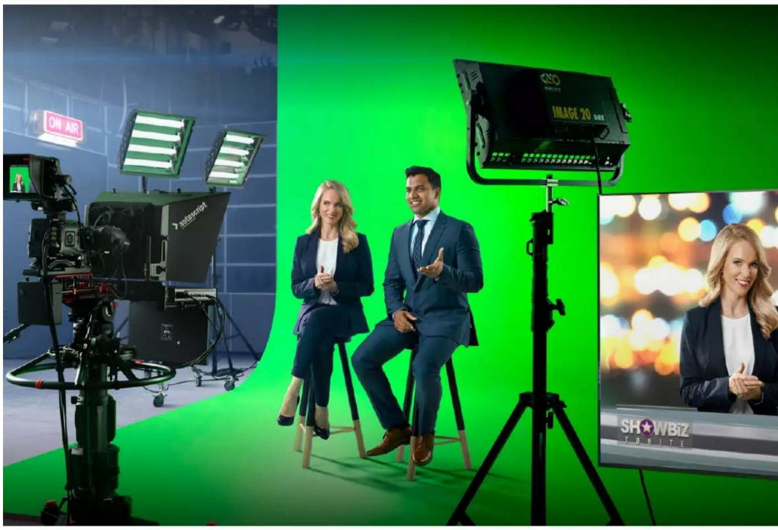

Gentile utente
CEO Blackmagic Design
Indices
I modelli Ultimatte 12 822
Cos' un matte? 822
Tipidimatte 823
Developer Information (English) 900
Controlling Ultimatte using Telnet 900
Blackmagic Ultimatte 12 Ethernet Protocol 901
Red, Green, e Blue Density
Matte Process/Screen Correction
Ambiance Level Red, Green, Blue
Ambiance Level Master
Direct Light Red, Green, Blue
LY Input Realistic/Linear/Additive
Window Position Top, Bottom, Left, Right
Window Softness Top, Bottom, Left, Right
Window Skew Top, Bottom, Left, Right
Frame Delay FG Input
FG Input UV Position
| Standard | Inputs |
| PGM Out | BG In |
| FG In | Layer In |
| BG In | BG Matte In |
| Combined Matte | Garbage Matte In |
| Internal Matte | Holdout Matte In |
| Fill Out | Layer Matte In |
2 Nella tab Options, premi Exit to Desktop.
Developer Information (English)
Controlling Ultimatte using Telnet
The Blackmagic Ultimatte 12 Ethernet Protocol gives you the freedom to build your own custom control solutions for your Ultimatte 12. For example, you can create your own software application and control your Ultimatte via Ethernet from your computer.
The first step is to connect your Ultimatte to your computer via Ethernet. You can do this by connecting Ultimatte to the same network your computer is connected to, or you can connect Ultimatte directly to your computer.
NOTE If your Blackmagic Ultimatte is connected directly to your computer, set your computer to a manual static IP address. Set the first three blocks of numbers in the IP address to match your Ultimatte and set the subnet mask to 255.255.255.0. You can leave the gateway or router setting blank as it will not be used in a direct connection between your computer and Ultimatte.
If your network settings are set correctly, you can now open the Terminal application on Mac OS, or enable Telnet command line utilities on Windows and enter Ultimatte control protocol commands. These commands can be programmed into your application and triggered by related items on a custom user interface of your own design.
Below is a basic example of using Telnet to change the backing color, restore to factory defaults, and adjust the matte density control.
1 In the Terminal application, type the following:
telnet (IP address of main unit (space) port number)(enter)
For example: telnet 192.168.10.220 9998
Press 'enter'.
A list of status information will appear and you are ready to control your Ultimatte.
2 Now type the following:
control: (press enter)
backing color: blue (press enter twice)
Terminal will acknowledge the action with 'ack' and confirm it so you know your setting has been performed.
You have now changed Ultimatte's backing color to blue.
3 To restore to factory defaults, type the following:
control: (press enter)
factory defaults: yes (press enter twice)
This restores your Ultimatte to factory default settings and performs an automatic composite.
4 To adjust the matte density setting, type the following:
control: (press enter)
matte density: 273 (press enter twice)
Terminal will acknowledge and confirm the action.
You have now adjusted the matte density setting.
5 To exit Telnet
Hold down the control button and press the 'J' key. The Telnet prompt will appear.
Type the following:
quit press enter)
A status message will appear confirming the connection is closed.
Blackmagic Ultimatte 12 Ethernet Protocol
Version 2.0
If you are a software developer you can use Ultimatte Ethernet Protocol to construct devices that integrate with our products. Here at Blackmagic Design our approach is to open up our protocols and we eagerly look forward to seeing what you come up with!
Overview
The Blackmagic Ultimatte Ethernet Protocol is a text based protocol that is accessed by connecting to TCP port 9998 on an Ultimatte.
Ultimatte sends information in blocks. Each block has an identifying header in all caps, followed by a full colon. A block spans multiple lines and is terminated by a blank line. Each line in the protocol is terminated by a newline character.
Upon connection, the Ultimatte device sends a complete update of its status. After the initial status transmission, status updates are sent every time the Ultimatte device's status changes.
To be resilient to future protocol changes, clients should ignore blocks they do not recognize, up to the trailing blank line. Within existing blocks, clients should ignore lines that they do not recognize.
Protocol Preamble
The first block sent by Ultimatte is always the protocol preamble:
PROTOCOL PREAMBLE: Version: 2.0
The version field indicates the protocol version. When the protocol is changed in a backwards compatible way, the minor version number will be updated. If incompatible changes are made, the major version number will be updated.
Identity
The next block contains information about the device identity.
ID EN T IY:
Model: Ultimatte 12 8K
Label: Ultimatte 12 8K
Unique ID: 12345678
Network Information
There are two network blocks. The first describes the general network information and the second describes the network interface details.
NETWORK: Interface count: 1 Default Interface: 0 Static DNS Ser vers: 8.8.8.8, 8.8.4.4 Cu rrent DNS Ser vers: 8.8.8.8, 8.8.4.4
NETWORK INTERFACE 0:
Name: Cadence GigE Ethernet MAC
Priority: 0
MAC Address: xx.xx.xx.xx.xx.xx
Dynam icIP: false
Cu rre nt A d d re s s: 10.0.0.2/255.255.255.0
Cu rre nt G ate way: 10.0.0-1
Static A dd resses: 10.0.0.2/255.255.255.0
Static Gate w ay: 10.0.0.1
Version Information
The version information describes the hardware and software version numbers and identifiers of the device. For example, the "Product ID" field contains the hexadecimal USB Product Identifier.
VERSION: Product ID: BE84 Hardware Version: 0100 Software Version: 09A89B7A Software Release: 2.Q
Device Information
The next block contains general information about the connected Ultimatte device.
NOTE Some Ultimatte models will only have a subset of the above-mentioned inputs.
For example, the Ultimatte 12 HD Mini only has the following inputs:
- Foreground input (FG In), and
Background input (BG In).
Similarly, the Ultimatte 12 HD only has the following inputs:
- Foreground input (FG In),
Background input (BG In),
Garbage Matte input (GMATTE In),
Holdout Matte input (H MATTE In),
Monitor Input (MONITOR In), and
Reference Input (REF In).
Video Formats Information
The Video Formats blocks lists the video formats supported by the device. See the Video Format Control list to find the formats supported by each device.
VIDEO FORMATS: auto detect 525.59.94 NTS C 4:3625i50 PAL 4:3720p60
…
Initial Status Dump
The next eleven blocks provide the control values, control default values, current file, file list, the GPI lists, the Frame Buffer Image List and Frame Buffer State.
CONTROL:
Matte Density: 0
Red Density: 0
Green Density: 0
...(Full list in Controls section)
<sup>+</sup>
CONTROL DEFAULT LT:
Matte Density: 0
Red Density: 0
Green Density: 0
...(Full list in Controls section)
<sup>+</sup>
CUR R ENT FILE
Filename <sup>+</sup>
<sup>+</sup>
FILE LIST:
File 1
File 2
<sup>+</sup>
GPI LIST:
ID: 1
Index: 0
File 1
File 2
NOTE The Ultimatte 12 HD Mini does not have GPI inputs, so this block is not available on that device.
The IMAGE LIST block contains the filenames of images that are currently stored on the device. These images can be assigned to Frame Buffer inputs.
IM AGE LIST: Image 1 Image 2
The FRAME BUFFER block contains the status of the Frame Buffers on the device.
This information will show:
How many image buffers are available,
- whether a frame buffer is enabled and has an image buffer assigned to it, and
- how frame buffer transitions are set up for those frame buffers that support transitions.
NOTE Frame Buffer Duration time is in milliseconds.
FRAME BUFFER: Number Of Frame Buffers: 46 BG 1 Frame Buffer Enable: off BG 1 Frame Buffer Index: 0 LY 1 Frame Buffer Enable: off LY 1 Frame Buffer Index: 0 BG 2 Frame Buffer Enable: off BG 2 Frame Buffer Index: 0 LY 2 Frame Buffer Enable: off LY 2 Frame Buffer Index: 0 GM Frame Buffer Enable: off GM Frame Buffer Index: 0 HM Frame Buffer Enable: off HM Frame Buffer Index: 0 BG Frame Buffer Mix: 0 LY Frame Buffer Mix: 0 BG Transition Duration: 0 LY Transition Duration: 0 Frame Buffer 1: Image 1 Frame Buffer 2: Image 2 ...
End Prelude
The final block of the status dump sent by Ultimatte is always end prelude:
END PRELUDE:
Status Updates
When any Control is changed on an Ultimatte device, the Ultimatte device replies with the applicable status block to all connected clients, containing only the items that have changed. For example, if Matte Density has been changed, the following block will be sent:
CONTROL: Matte Density: 0
If multiple items are changed, multiple items may be present in the update:
CONTROL: Matte Density: 0 Red Density: 0
These notifications are sent whether the change originated from the front panel, or from any other connected client.
Requesting Changes
To update a Control the client should send a block of the same form Ultimatte sends when its status changes. For example, to change Matte Density to 100, the client should send the following block:
CONTROL: Matte Density: 100
The block must be terminated by a blank line. On receipt of a blank line, Ultimatte will either acknowledge the request by responding:
ACK←
←
or indicate that the request was not understood by responding:
NAK
After a positive response, the client should expect to see a status update from Ultimatte showing the status change. This is likely to be the same as the command that was sent, but if the request could not be performed, or other changes were made simultaneously by other clients, there may be more updates in the block, or more blocks. Simultaneous updates could cancel each other out, leading to a response that is different to that expected.
In the absence of simultaneous updates, a simple control change will result in the following protocol exchange:
CONTROL:
Matte Density: 0 ACK
CONTROLC:
Matte Density: 0
The asynchronous nature of the responses means that a client should never rely on the desired update actually occurring and must simply watch for status updates from Ultimatte and use only these to update its local representation of Ultimatte's state.
A client may also request Ultimatte to change a control by a relative amount. For example, to change Matte Density by 10, the client should send the following block:
CONTROL:
Offset Matte Density: 10
Only controls with numerical ranges support this relative mode.
Requesting a Status Dump
The client may request that Ultimatte resend the complete state of any status block by sending the header of the block, followed by a blank line. In the following example, the client requests Ultimatte resend the control status:
CONTROL: ACK
CONTROL:
Matte Density: 0
Red Density: 0
Green Density: 0
... (Full list in Controls section)
File System
The client may request that Ultimatte load, save, delete, or rename a file. To load a file the client should send the following block:
FILE:
Load:
Ultimatte will respond with an ACK followed by a Current File block or a Message block.
To save, delete, or rename a file the client should send one of the following blocks:
FILE:
Save: <filename>
<
FILE:
Delete: <filename>
<
FILE:
Rename: <filename>
To: <filena me>
<
In each case Ultimatte will respond with an ACK followed by a File List block or a Message block.
GPI Event List
The client may request that Ultimatte add, insert or remove an event to a GPI Event List by sending an Insert GPI Event or Remove GPI Event command, followed by a blank line.
For example, to insert an event, the client should send the following block:
GPI:
ID: 1
Insert: <filename>
At: -1 {The insertion index. A '-1' represents the end of the list}
To remove an event a client would send the following block:
GPI:
ID: 1
Remove: 1 ← {Event index to remove. A '0' will delete all events}
To set the current event index a client would send the following block:
GPI: ID: 1 Index: 1
Ultimatte will respond with an ACK message followed by either a GPI List Block or a Message Block.
GPI LIST:
ID: 1
Index: 0
File 1
File 2
...
or
MESSAGE:
Warning: Event limit exceeded
Frame Buffer
The client may request that the Ultimatte device assign a pre-loaded image from its Media Pool into a particular frame buffer and enable/disable the frame buffer. To assign and enable an image to the BG frame buffer the following commands are required:
FRAME BUFFER:←
BG 1 Frame Buffer Index: 1 BG 1 Frame Buffer Enable: on-
To disable the frame buffer only the enable command is required:
FRAME BUFFER: BG1FrameBufferEnable:on
NOTE The Telnet interface does not currently provide loading or removing images in the Media Pool. This has to be done from either a Smart Remote 4, or using the Software Control application. Refer to the 'using the media pool' section of this manual for more information.
Camera Control
Ultimatte 12 HD Mini can be used to control an attached camera via SDI or HDMI, please refer to the 'Camera Control via Ultimatte 12 HD Mini' section for more information. For SDI Camera Control, the Ultimatte device's Camera ID may be changed using the CAMERACONTROL block:
CAMERACONTROI CameraId:1←
NOTE This control block is only available on the Ultimatte 12 HD Mini.
| Controls | |
| Matte Density 0-10000 | |
| Black Gloss 0-10000 | |
| Blue Density 0-10000 | |
| Green Density 0-10000 | |
| Red Density 0-10000 | |
| Shadow Level 0-10000 | |
| Shadow Threshold 0-10000 | |
| Matte Correct Horizontal Size 0-6 | |
| Matte Correct Vertical Size 0-3 | |
| Cursor X 0-10000 | |
| Cursor Y 0-10000 | |
| Cursor 2 X 0-10000 | |
| Cursor 2 Y 0-10000 | |
| Vell Master 0-10000 | |
| Vell Red 0-10000 | |
| Vell Green 0-10000 | |
| Vell Blue 0-10000 | |
| Vell Correct Horizontal Size | 0-6 |
| Vell Correct Vertical Size | 0-61 |
| Wall Color Red | 0-10000 |
| Wall Color Green | 0-10000 |
| Wall Color Blue | 0-10000 |
| Floor Color Red | 0-10000 |
| Floor Color Green | 0-10000 |
| Floor Color Blue | 0-10000 |
| Cleanup Level 0-10000 | |
| Cleanup Dark Recover | 0-10000 |
| Cleanup Light Recover | 0-10000 |
| Cleanup Strength | 0-10000 |
| GM Cleanup Level | 0-10000 |
| GM Cleanup Dark Recover | 0-10000 |
| GM Cleanup Light Recover | 0-10000 |
| GM Cleanup Strength | 0-10000 |
| Correction Level | 0-10000 |
| Noise Level | 0-10000 |
| Black Balance 0-10000 | |
| Gray Balance | 0-10000 |
| White Balance 0-10000 | |
| Flare Level 0-10000 | |
| Cool 0-10000 | |
| Skin Tone 0-10000 | |
| Light Warm 0-10000 | |
| Dark Warm 0-10000 | |
| Flare Correct Horizontal Size 0-6 | |
| Flare Correct Vertical Size 0-6 | 1 |
| Ambiance Master 0-10000 | |
| Ambiance Red 0-10000 | |
| Ambiance Green 0-10000 | |
| Ambiance Blue 0-10000 | |
| Ambiance Strength 0-10000 | |
| Direct Light Red | 0-10000 |
| Direct Light Green | 0-10000 |
| Direct Light Blue | 0-10000 |
| Direct Light Mix | 0-10000 |
| Vertical Blur | 0-10000 |
| FG Saturation Red | 0-10000 |
| FG Saturation Green | 0-10000 |
| FG Saturation Blue | 0-10000 |
| FG Saturation Master | 0-10000 |
| FG Contrast Red | 0-10000 |
| FG Contrast Green | 0-10000 |
| FG Contrast Blue | 0-10000 |
| FG Contrast Master | 0-10000 |
| FG Black Red | 0-10000 |
| FG Black Green | 0-10000 |
| FG Black Blue | 0-10000 |
| FG Black Master | 0-10000 |
| FG White Red | 0-10000 |
| FG White Green | 0-10000 |
| FG White Blue | 0-10000 |
| FG White Master | 0-10000 |
| FG Contrast Crossover | 0-10000 |
| Fade Mix | 0-10000 |
| BG Saturation Red | 0-10000 |
| BG Saturation Green 0-10000 | |
| BG Saturation Blue 0-10000 | |
| BG Saturation Master 0-10000 | |
| BG Contrast Red 0-10000 | |
| BG Contrast Green 0-10000 | |
| BG Contrast Blue 0-10000 | |
| BG Contrast Master 0-10000 | |
| BG Black Red 0-10000 | |
| BG Black Green 0-10000 | |
| BG Black Blue 0-10000 | |
| BG Black Master 0-10000 | |
| BG White Red 0-10000 | |
| BG White Green 0-10000 | |
| BG White Blue 0-10000 | |
| BG White Master 0-10000 | |
| BG Contrast Crossover 0-10000 | |
| BG Filter 0-10000 | |
| Test Signal Master | 0-10000 |
| Test Signal Red | 0-10000 |
| Test Signal Green | 0-10000 |
| Test Signal Blue | 0-10000 |
| LY Saturation Red | 0-10000 |
| LY Saturation Green | 0-10000 |
| LY Saturation Blue | 0-10000 |
| LY Saturation Master 0-10000 | |
| LY Contrast Red | 0-10000 |
| LY Contrast Green | 0-10000 |
| LY Contrast Blue | 0-10000 |
| LY Contrast Master 0-10000 | |
| LY Black Red | 0-10000 |
| LY Black Green | 0-10000 |
| LY Black Blue | 0-10000 |
| LY Black Master | 0-10000 |
| LY White Red | 0-10000 |
| LY White Green | 0-10000 |
| LY White Blue | 0-10000 |
| LY White Master | 0-10000 |
| LY Contrast Crossover 0-10000 | |
| LY Filter 0-10000 | |
| LY Test Signal Master 0-10000 | |
| LY Test Signal Red 0-10000 | |
| LY Test Signal Green 0-10000 | |
| LY Test Signal Blue 0-10000 | |
| LY Fade Mlx 0-10000 | |
| Lighting Level Red 0-10000 | |
| Lighting Level Green 0-10000 | |
| Lighting Level Blue 0-10000 | |
| Lighting Level Master 0-10000 | |
| Lighting Minimum Level 0-10000 | |
| Window Position Top 0-[Based on Video Format] | |
| Window Position Bottom 0-[Based on Video Format] | |
| Window Position Left 0-[Based on Video Format] | |
| Window Position Right 0-[Based on Video Format] | |
| Window Softness Top 0-10000 | |
| Window Softness Bottom | 0-10000 |
| Window Softness Left 0-10000 | |
| Window Softness Right | 0-10000 |
| Window Skew Top 0-10000 | |
| Window Skew Bottom | 0-10000 |
| Window Skew Left | 0-10000 |
| Window Skew Right | 0-10000 |
| Window Skew Offset Top | 0-10000 |
| Window Skew Offset Bottom | 0-10000 |
| Window Skew Offset Left | 0-10000 |
| Window Skew Offset Right | 0-10000 |
| Transition Rate | 1-120 |
| BM Process Horizontal | 0-3 |
| BM Process Vertical | 0-3 |
| BM Filter | 0-10000 |
| BM Input Level | 0-10000 |
| BM Input Offset | 0-10000 |
| GM Process Horizontal | 0-3 |
| GM Process Vertical | 0-3 |
| GM Filter | 0-10000 |
| GM Input Level 0-10000 | |
| GM Input Offset 0-10000 | |
| HM Process Horizontal 0-3 | |
| HM Process Vertical 0-3 | |
| HM Filter 0-10000 | |
| HM Input Level 0-10000 | |
| HM Input Offset 0-10000 | |
| LM Process Horizontal 0-3 | |
| LM Process Vertical 0-3 | |
| LM Filter 0-10000 | |
| LM Input Level 0-10000 | |
| LM Input Offset 0-10000 | |
| Noise Cursor X 0-10000 | |
| Noise Cursor Y 0-10000 | |
| FG Input Frame Delay 0-14 | |
| FG Input U Position 0-10000 | |
| FG Input V Position | 0-10000 |
| FG Input UV Position | 0-10000 |
| Talent Highlight Level** | 0-10000 |
| Monitor Highlight Level | 0-10000 |
| Matte Out Level 0-10000 | |
| Output Offset | -1500-+1500 |
| GP Out Delay* | 1-120 |
| GP1 Input Delay* | 1-120 |
| GP2 Input Delay* | 1-120 |
| GP3 Input Delay* | 1-120 |
| GP4 Input Delay* | 1-120 |
| GP5 Input Delay* | 1-120 |
| Matte Enable | On/Off |
| Screen Correct On/Off | |
| GM Cleanup Enable | On/Off |
| Noise Enable | On/Off |
| Noise Cursor Enable | On/Off |
| FG Freeze | On/Off |
| FG Advanced Contrast Enable | On/Off |
| Advanced Flare Enable | On/Off |
| HM Flare Enable | On/Off |
| Ambiance Enable On/Off | |
| BG Gradient Enable On/Off | |
| BG Freeze On/Off | |
| BG Advanced Contrast Enable On/Off | |
| BG Test Signal Enable On/Off | |
| LY Input Enable On/Off | |
| LY Advanced Contrast Enable On/Off | |
| LY Freeze** On/Off | |
| LY Test Signal Enable On/Off | |
| Lighting Enable On/Off | |
| Window Enable On/Off | |
| Window BM Enable On/Off | |
| Window GM Enable | On/Off |
| Window HM Enable | On/Off |
| Window LM Enable | On/Off |
| Window Invert | On/Off |
| Wall Cursor Position Enable | On/Off |
| Floor Cursor Position Enable | On/Off |
| Dual Cursor | On/Off |
| Manual Color Enable | On/Off |
| Custom Powerup(deprecated) | On/Off |
| BM Enable | On/Off |
| BM Invert | On/Off |
| BM Process Invert | On/Off |
| BM Freeze** | On/Off |
| GM Enable | On/Off |
| GM Invert | On/Off |
| GM Process Invert | On/Off |
| GM Freeze* | On/Off |
| HM Enable | On/Off |
| HM Invert | On/Off |
| HM Process Invert | On/Off |
| HM Freeze* | On/Off |
| LM Invert | On/Off |
| LM Process Invert | On/Off |
| Monitor To Program | On/Off |
| Monitor To Talent** | On/Off |
| Fill Linear Mix Correction* On/Off | |
| Talent Mirror** On/Off | |
| Monitor Cascade On/Off | |
| Matte Out Invert* On/Off | |
| On Air Enable On/Off | |
| On Air Lockout On/Off | |
| Matte View Range On/Off | |
| Matte View Invert On/Off | |
| Monitor Out RGB On/Off | |
| Monitor Out Red Only On/Off | |
| Monitor Out Green Only On/Off | |
| Monitor Out Blue Only On/Off | |
| GP Out Save* On/Off | |
| Quickload 1 | On/Off |
| Quickload 2 | On/Off |
| Quickload 3 | On/Off |
| Quickload 4 | On/Off |
| Quickload 5 | On/Off |
| Quicksave 1 | On/Off |
| Quicksave 2 | On/Off |
| Quicksave 3 | On/Off |
| Quicksave 4 | On/Off |
| Quicksave 5 | On/Off |
| GP1 Input Enable* On/Off | |
| GP2 Input Enable* | On/Off |
| GP3 Input Enable* | On/Off |
| GP4 Input Enable* | On/Off |
| GP5 Input Enable* | On/Off |
| GP1 High Enable* | On/Off |
| GP2 High Enable* | On/Off |
| GP3 High Enable* On/Off | |
| GP4 High Enable* On/Off | |
| GP5 High Enable* | On/Off |
| Tally Active | On/Off [Read Only] |
| 3G SDI level | A/B |
| Color Space* | Rec.709/Rec.2020 |
| Filter Mode | Median/Average |
| Filter Median 0/1/2/3/4 | |
| Filter Average 0/1/2/3/4 | |
| LY In Mix Mode Realistic/Linear/Additive | |
| Backing Color Red/Green/Blue | |
| Cursor Position Default/Last | |
| GP Out Level" High/Low | |
| Output Range Normal/Full | 2 |
| Monitor Out Program, FG, BG, Combined | Matte, Internal Matte, Fill, Layer In, Background Matte In, Garbage Matte In, Holdout Matte In, Layer Matte In, Processed LM, Processed HM, Processed GM, Processed BM, Screen Correction |
| Layer Order FG/Layer/BG Layer/BG, Layer/FG/ | BG Layer/BG, Layer/BG Layer/FG/BG, BG Layer/Layer/FG/BG, BG Layer/FG/ |
| Layer/BG, FG/BG Layer/Layer/BG, FG/BG Layer/BG, BG Layer/FG/BG, FG/Layer/BG, Layer/FG/BG | |
| Video Format Auto Detect, 525i59.94 NTSC 4:3, | 625i50 PAL 4:3, 720p60, 720p59.94, 720p50, 1080i60, 1080i59.94, 1080i50, 1080p60, 1080p59.94, 1080p50, 1080p30, 1080p29.97, 1080p25, 1080p24, 1080p23.98, 1080PsF30, 1080PsF29.97, 1080PsF25, 1080PsF24, 1080PsF23.98, 2160p60, 2160p59.94, 2160p50, 2160p30, 2160p29.97, 2160p25, 2160p24, 2160p23.98, 4320p60, 4320p59.94, 4320p50, 4320p30, 4320p29.97, 4320p25, 4320p24 and 4320p23.984 |
| Factory Defaults Yes | 5 |
| User Defaults Yes | 5 |
| Auto Screen Sample Yes | 5 |
| Screen Capture Yes | 5 |
| Noise Select | Yes5 |
| Sample Wall | Yes5 |
| Sample Floor | Yes5 |
| Matte Reset Yes | 5 |
| Cleanup Reset | Yes5 |
| GM Cleanup Reset | Yes5 |
| FG Color Reset | Yes5 |
| BG Color Reset Yes | 5 |
| Flare Reset | Yes5 |
| Ambiance Reset Yes | 5 |
| BG Test Signal Color Reset Yes | 5 |
| LY Color Reset Yes | 5 |
| LY Test Signal Color Reset Yes | 5 |
| Window Reset Yes | 5 |
| Window Skew Reset Yes | 5 |
| GP Out* Yes | 5 |
1 These ranges are Ultimatte device dependent. For Ultimate 12 8K running protocol 2.0, the range is 0-6. For Ultimatte 12 running version 1.2, the range is 0-3.
2 These controls are only available in protocol version 2.0 and up.
3 Loop outputs for 'garbage matte' and 'holdout matte' inputs are available for Ultimatte 12, not Ultimatte 12 8K.
4 Supported video formats are Ultimatte device dependent. 4320p formats are available for Ultimatte 12 8K. Ultimatte 12 HD Mini does not support PsF video formats.
5 These controls represent functions. Send 'Yes' to execute the function. Ultimatte will respond with a 'Yes' to indicate the function is complete.
* These controls are not available on the Ultimatte 12 HD Mini
These controls are not available of the Ultimatte 12 HD or HD Mini
| Glossary | |
| FG | Foreground |
| BG | Background |
| LY | Layer |
| GM | Garbage Matte |
| BM | Background Matte |
| HM | Holdout Matte |
| LM | Layer Matte |
Assistenza clienti
Assistenza tecnica
Ajustar Brightness, Color, Contrast Saturation 964
Botoes do Menu Principal
Red Density, Green Density e Blue Density
Matte Process/Screen Correction
Matte Correct Vertical Size
Black, Gray e White Balance
Ambiance Level Red, Green, Blue
Ambiance Level Master
Estacnagaoajusto nvelgerdaambienciaqueinfluenciaraosnveisdascoresdo primeiro plano.Aoajustarestecontrole,a diferencarelativaentreoscomponentesvermelho,verde e azul do ambiente sera mantida.
Ambiance Strength
Direct Light Red, Gree, Blue
Ajustar Brightness, Color, Contrast e Saturation
Lighting Level - Red/Green/Blue
Lighting Level - Master
Layer Input Realistic/Linear/Additive
Window Position Top/Bottom/Left/Right
Window Softness Top/Bottom/Left/Right
Window Skew Top/Bottom/Left/Right
Window Skew Offset Top/Bottom/Left/Right
Foreground Input UV Position
Fill Linear Mix Correct
GPI OUT Delay Frames
Monitor Out Red, Green e Blue
| Standard | Inputs |
| PGM Out | BG In |
| FG In | Layer In |
| BG In | BG Matte In |
| Combined Matte | Garbage Matte In |
| Internal Matte | Holdout Matte In |
| Fill Out | Layer Matte In |