Ninfa - Cooker EDILKAMIN - Free user manual and instructions
Find the device manual for free Ninfa EDILKAMIN in PDF.
| Product type | Wood-burning stove |
| Brand | Edilkamin |
| Model | Ninfa |
| Overall thermal output | 12 kW (estimated) |
| Hourly wood consumption | 2.5 kg/h (estimated) |
| Flue outlet diameter | 150 mm (estimated) |
| Heating volume | 150 m³ (estimated) |
| Weight | 120 kg (estimated) |
| Dimensions (L x D x H) | 60 x 50 x 90 cm (estimated) |
| Baking oven | Yes, stainless steel |
| External air intake | Minimum cross-section of 200 cm² |
| Firebox materials | Cast iron, cast iron grate, steel sheet cladding 2 mm |
| Exterior cladding | Enameled refractory ceramic |
| Fuel | Wood (dry beech/birch) or lignite briquettes (max 3) |
| Main functions | Oven cooking, radiant and convection heating, primary and secondary air adjustment, self-cleaning glass |
| Routine maintenance | Cleaning glass with special product, emptying ash drawer, periodic cleaning of firebox |
| Flue maintenance | Sweep at least once a year |
| Safety | Locked door, anti-burn handle, safety distances (80 cm from furniture, 10 cm from wall) |
| Ceramic assembly | Assembly possible with aluminum uprights and inserts |
| Repairability | Spare parts available (contact dealer) |
Frequently Asked Questions - Ninfa EDILKAMIN
User questions about Ninfa EDILKAMIN
0 question about this device. Answer the ones you know or ask your own.
Ask a new question about this device
Download the instructions for your Cooker in PDF format for free! Find your manual Ninfa - EDILKAMIN and take your electronic device back in hand. On this page are published all the documents necessary for the use of your device. Ninfa by EDILKAMIN.
USER MANUAL Ninfa EDILKAMIN
- Wood-burning stoves must be installed "in a workmanlike manner" in compliance with the SAFETY REGULATIONS in force and, most importantly, by qualified expert staff.
- We advise you to read these instructions and general rules of conduct carefully in order to get the most from your wood-burning stove.
- Furthermore, due to the distinct characteristics of each installation, Italiana Camini declines all responsibility for breakdown, damage or malfunction caused by failure to comply with these instructions for use.
CAUTION:
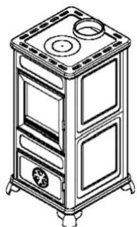
The stove has been designed to work with the door closed only. Heat is propagated by radiation and convection simultaneously.
INSTALLATION
- The stove is delivered on a pallet covered with a cardboard box. The first thing to do is remove the stove from its packaging, check that the model is the one ordered, and make sure it has not been damaged during transport. Any complaints must be made to the carrier (in writing on the accompanying consignment note) when the stove is received.
- Before positioning the stove, make sure the flue is suitable for the smoke produced. The fact an old oven or stove connected to the same flue worked correctly does not necessarily mean the new one will work well.
- When installing the wood-burning stove, take the position of the flue into consideration; the size of the flue must comply with the specifications shown in the table in these instructions. It is advisable to use insulated circular section flues made of refractory material or stainless steel, with smooth internal walls. The flue cross-section should be constant for its whole length (a minimum height of 3,5 - 4 m is advisable). It is advisable to fit a chamber at the base of the flue to collect solid material and any condensate. Dilapidated flues and flues made of unsuitable materials (asbestos, galvanized steel, corrugated iron, etc.) with rough or porous internal surfaces are illegal and detrimental to stove operation.
- The room where the stove is installed must have a suitable outside air intake with a through surface area of at least 200cm^2 to replenish the burnt oxygen and ensure an adequate flow of combustion air.
- Place the stove (DIS. 1) away from flammable materials and objects; leave a distance of 80 cm from furniture and at least 10 cm from the wall. These distances are for furniture or walls which are either fireproof or able to withstand being raised to an environmental temperature of 80^ C without overheating to the point that they catch fire. The air circulation which is created around the stove thanks to these distances ensures efficient ventilation and improves thermal efficiency.
- If the stove is installed on a floor made of a flammable material, it is advisable to place it on a steel plate, which is available as an optional extra.
- For a good draught, the flue should be free from obstructions, such as bottlenecks, horizontal sections and sharp edges;
- The chimney pot must have a wind guard, an internal section equivalent to that of the flue, and smoke outlet cross-section at least twice that of the internal flue cross-section.
- To avoid problems with the draught, every stove must have its own independent flue. If there are several flues on the roof, the others should be at least 2 metres away and the stove chimney pot should be at least 50~cm higher than the others.
Figures 2 and 3 (pag. 42) show the UNI Standard 10683 requirements regarding distances between chimney pots and their positions.
UNI (Italian Standards Institution) chimney pot standard 10683, examples of distances and positions (TAB. 1 pag. 42)
A = Slope of roof
B = Distance between the roof ridge axis and the stack *
C = Minimum height between the outlet and the roof
* if the distances are less than or equal to those shown, the chimney pot must be at least 50 cm higher than the roof ridge
N.B. If the flue to be used has previously been used for other stoves or fireplaces, it must be carefully cleaned to prevent faulty operation and avert the risk of unburnt deposits on the internal flue walls catching fire. In normal working conditions, the flue must be cleaned at least once a year.
N.B. For optimum operation, the flue draught must create a pressure drop of between 0.12 and 0.2 mbars. Lower values may lead to unpleasant smoke emissions when loading the stove and produce excessive soot deposits; higher values would lead to excessively fast combustion and a decrease in thermal efficiency. To fall within the correct values, it is enough to comply with the UNI Standard 10683 table.
N.B. ITALIANA CAMINI (Division Edilkamin S.p.A.) declines all responsibility for installations which do not comply with the laws in force and for misuse of the stove.
STOVE SPECIFICATIONS (TAB. 2 pag. 42)
A = Heat output
B = Hourly wood consumption *
C = Smoke outlet pipe diameter
D = Heatable room dimensions m ^3
E = Weight
F = Stove dimensions (width)
G = Stove dimensions (depth)
H = Stove dimensions (height)
I = Oven
L = Air intake
* wood consumption greater than that shown could cause damage to the firebox and external ceramic covering
DAFNE FORNO, ELF FORNO STOVE
The Dafne oven and Elf oven stove has a stainless steel oven for cooking all kinds of food (fruit, meat, desserts, etc.). For best results, the oven must be kept at the right temperature for the particular food to be cooked. To change the temperature, simply turn the primary air valve on the firebox.
To increase the temperature, turn the valve anticlockwise; to decrease it, turn the valve clockwise.
CONSTRUCTIONAL CHARACTERISTICS
- Cast iron firebox door with ceramic glass pane and chrome-plated steel handle with burn preventing insert.
- Firebox with basket and grate completely made of cast iron with 2 mm sheet metal cladding for optimum operation: the primary air may be adjusted using the valve (DIS. 4 - A) found in the middle of the lower door. To increase combustion air, turn the valve anticlockwise; to decrease it, turn the valve clockwise.
- The secondary air reaches the firebox in a fixed quantity through the openings in the upper glass holder on the fire door.
Besides keeping the ceramic glass pane clean, the secondary air burns any gases which may be given off by incomplete wood combustion, therefore reducing emissions of unburnt material into the environment. - The knob (DIS. 4 - B) on the inside of the lower door is for cleaning the grate (grate shaker); it is advisable to use it when the stove is alight every time the flame tends to die down.
- The ashpan (DIS. 4 - C) inside the lower door should be checked regularly and emptied if necessary. To pull it out, lift slightly using the handgrip.
- The stove is covered in refractory ceramic tiles available in various colours.
The tiles are fixed in place with external painted aluminium guides.
INSTRUCTIONS FOR USE
Caution: when the fire is alight, some parts of the stove reach high temperatures. It is therefore advisable to keep any children who may approach the stove under control. It is not advisable to keep heat sensitive objects near the stove (plastic, etc.).
Nearby extractor hoods may draw unburnt gases out into the room when the stove is alight.
Hot ash must never be poured into waste bins since it may cause fire.
Caution: the firebox door reaches high temperatures when the fire is alight. To load wood, open the door in two stages: first slowly and partially (3 or 4 cm), then - after a few seconds - completely, thus preventing smoke from getting out through the door.
FIRST LIGHTING (DIS. 4 pag. 43)
Any unpleasant smells or smoke are caused by materials used during construction evaporating or drying. This tends to die down after a few days.
- Proceed as follows: put screwed up paper balls in the firebox and cover with a few twigs or a few pieces of thin well seasoned wood, so that the flames grow as much as possible.
- Open combustion air valve A and open the draught valve (if fitted) on the flue connecting pipe (smoke duct).
- Light the paper and add about half the recommended amount of wood as the flames grow (see wood consumption table). As soon as the flames go out and a good bed of embers has formed, load the firebox with the normal amount of wood.
- If the fire is too lively, it is advisable to close the combustion air valve partially by turning valve A and slightly close the draught valve (if fitted) on the flue connecting pipe (smoke duct)
- Make sure the firebox door is always tightly shut when the fire is alight; if it remains open for a long time, smoke may get out.
N.B.: do not use alcohol, petrol, kerosene or other liquid fuels to light the fire. Keep liquid fuels away from the fire. Do not use firelighters made from petroleum or chemical substances: they may cause serious damage to the firebox walls. Only use eco-friendly firelighters.
Overloading (more kilos than in the table shown earlier) or excessively lively flames may damage the firebox compartment and the external covering.
SECONDARY AIR
Secondary air is the air which flows in the upper part of the flame. Gases which are not burnt during wood combustion itself catch alight and burn on the top of the flame, thus optimizing heat output and reducing emissions of unburnt material into the atmosphere.
TYPE OF FUEL
The stove should preferably be loaded with well seasoned beech/birch wood or with lignite briquettes (three pieces at most in order not to damage the firebox and outer covering due to the high level of heat these give off). Every type of wood has different characteristics and these affect combustion output. The rated output (in kW) declared may be obtained by burning the right amount of wood and being careful not to overload the combustion chamber (firebox).
ASH REMOVAL
The ashpan under the firebox door must be emptied as soon as it is full since, otherwise, the ash could cause the cast iron firebox grate to overheat and block air flow in the firebox itself. In any case, it is advisable to empty the ashpan regularly to optimize firebox combustion air intake. It is advisable to empty the stove when cold, for example every morning before lighting.
CLEANING THE GLASS PANE
Use the specific detergent available from dealers to clean the inside glass surface.
Do not clean the glass during stove operation or while hot!
N.B.: ceramic glass withstands high temperatures, but it is fragile, so protect it from accidental blows!
CLEANING THE CERAMIC COVERING
The ceramic covering must be cleaned with a gentle detergent and damp cloth. Do not use cold water when the stove is hot since the sudden temperature change could damage the ceramic covering.
CLEANING THE FIREBOX
Clean the firebox compartment regularly or, in any case, when soot deposits become excessive. This leads to better stove operation and output.
CLEANING THE FLUE
This must be done before periods of stove use and every time you see a layer of soot and tar (easily flammable substances) on the inside of the duct. When deposits reach a thickness of 5 - 6 mm, high temperatures and sparks may set them on fire with easily imaginable consequences both for the flue and your home. It is therefore advisable to clean the flue at least once a year or in any case when necessary.
FITTING THE CERAMIC TILES (TAB. 3 pag. 42)
The DAFNE, DAFNE OVEN, NINFA, ELF, ELF OVEN stoves have a metal and cast iron structure with four painted aluminium uprights with grooves for fitting ceramic tiles.
The table below shows the number and type of tiles needed for each model:
DESCRIPTION
A = side tiles
B = front tiles
C = side tiles
D = side tiles
E = front tiles
I = burgundy red full series tiles
L = leather full series tiles
M= beige full series tiles
N= soap stone full series tiles
The stoves are delivered with the ceramic tiles separately packed to avoid breakage and damage during transport.
The rear tile faces may have fine surface cracks, which however do not affect their quality in the slightest.
Unpack the tiles only once they are on the installation site.
Each stove is fitted with its ceramic covering during construction and testing, to make sure assembly is as quick and easy as possible.
The tiles are then removed and packed separately.
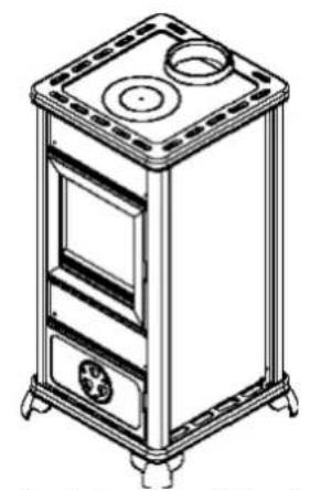
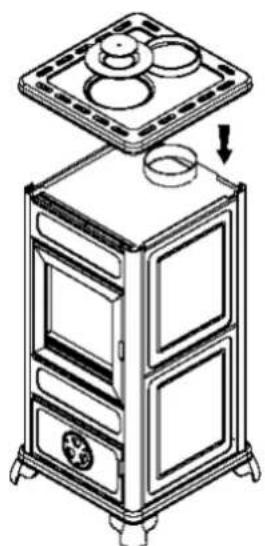
Ceramic tile fitting procedure (DIS. 5 pag. 43)
- figure 1 shows the stove as it is delivered
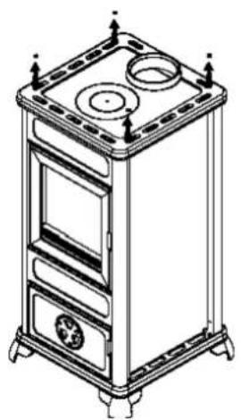
- remove the top by unscrewing the 4 screws (fig. 2).
- slip the front bar out by lifting it (fig. 3).
- slip the tiles in place in the front panels (fig. 4).
- put the front bar back in place as before.
- slip the ceramic tiles into the side guides provided, from top to bottom (fig. 5).
- put the top back on the frame and tighten the 4 screws (fig. 6).
- fig. 7 shows the fully assembled stove.
INFORMATIE PENTRU INSTALATOR
NB:
-Instalarea sobelor cu lemne se va face in conformitate cu Normele de Siguranta in vigoare, de catre persoane competente si calificate.
-UNI -(Institutul Italian De Standardizare)
UNI 10683 - Cosuri, exemple de distante si pozitionari. (Tab 1 pag. 42)
text_image
Technical diagram showing three views (A, A1, A2) of a device with labeled components and internal features, likely illustrating a mechanical or electrical assembly.DIS. 5
natural_image
Line drawing of a simple electrical cabinet with three circular vented lights and a fan (no text or symbols)fig. 1 fig. 2 fig. 3 fig. 4
natural_image
Line drawing of a multi-tiered industrial or electrical cabinet with ventilation grilles and mounting feet (no text or symbols)
natural_image
Line drawing of a portable oven with a vertical tube and fan, no text or symbols present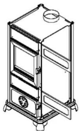
natural_image
Technical line drawing of a multi-level industrial cabinet or oven unit with ventilation grilles and a top vent (no text or symbols)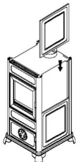
natural_image
Line drawing of a multi-tiered computer tower with a monitor on top, showing internal compartments and a hanging device (no text or symbols)fig. 5 fig. 6 fig. 7
natural_image
Line drawing of a multi-tiered industrial stove or oven unit with a top shelf and side panels, showing internal components and airflow direction (no text or symbols)