
TRESOR - Cooker EDILKAMIN - Free user manual and instructions
Find the device manual for free TRESOR EDILKAMIN in PDF.
| Product type | Pellet stove |
| Brand | Edilkamin |
| Model | TRESOR |
| Nominal power | 15 kW |
| Water power | 12 kW |
| Overall efficiency | 91,6 % |
| Max pressure | 3 bar |
| Operating pressure | 1,5 bar |
| Flue gas outlet temperature | 129 °C |
| Minimum draft | 12 / 5 Pa |
| Autonomy min/max | 5 / 18 hours |
| Fuel consumption min/max | 1 / 3,4 kg/h |
| Pellet hopper capacity | 21 kg |
| Heating volume | 390 m³ |
| Weight | 240 kg |
| Flue pipe diameter | 80 mm |
| External air intake diameter | 40 mm |
| Power supply | 230 V +/-10% 50 Hz |
| Average power consumption | 100 W |
| Ignition power consumption | 400 W |
| Fuel | Wood pellets (diameter 6 mm) |
| Control system | Leonardo® for optimal combustion |
| Functions | Water and air heating, possible DHW production |
| Maintenance | Daily (crucible, ashes), weekly (fireplace), seasonal by dealer |
| Safety | Thermocouple, air flow sensor, safety thermostat, 3 bar valve, etc. |
Frequently Asked Questions - TRESOR EDILKAMIN
User questions about TRESOR EDILKAMIN
0 question about this device. Answer the ones you know or ask your own.
Ask a new question about this device
Download the instructions for your Cooker in PDF format for free! Find your manual TRESOR - EDILKAMIN and take your electronic device back in hand. On this page are published all the documents necessary for the use of your device. TRESOR by EDILKAMIN.
USER MANUAL TRESOR EDILKAMIN
Congratulations and thank you for choosing our product.
Please read this document carefully before you use this product in order to obtain the best performance in complete safety.
For further details or assistance, please contact the DEALER where you purchased the product or visit our website www.edilkamin.com. and click on DEALERS.
NOTE
- After having unpacked the boiler-stove, ensure that its contents are complete and intact (covering, remote control with display, pipe fitting complete with clamp and silicone gasket, "cold hand" handle, guarantee booklet, glove, CD/specifications, spatula, dehumidifying salt, allen wrench).
In case of anomalies please contact the dealer where you purchased the product immediately.
You will need to present a copy of the warranty booklet and valid proof of purchase.
- Commissioning/ testing
Commissioning and testing must be performed by the DEALER. Failure to do so will void the warranty.
Commissioning, as specified in standard UNI 10683 consists in a series of inspections to be performed with the boiler-stove installed in order to ascertain the correct operation of the system and its compliance to applicable regulations.
-
Incorrect installation, incorrect maintenance, or improper use of the product, shall relieve the manufacturer from any damage resulting from the use of this product.
-
the proof of purchase tag, necessary for identifying the boiler-stove, is located:
-
on the top of the package
-
in the warranty booklet found inside the fi rebox
-
on the ID plate affixed to the back side of the unit;
This documentation must be saved for identification together with the valid proof of purchase receipt. The data contained therein must be reported when requesting information and made available should servicing be required;
- All images are for illustration purposes only; actual products may vary.
The undersigned EDILKAMIN S.p.a. with head office headquarters at Via Vincenzo Monti 47 - 20123 Milan - Italy - VAT IT00192220192
Declares under its own responsibility as follows:
The pellet Boiler-stoves illustrated below conforms to Regulation EU 305/2011 (CPR) and to the harmonised European Standard EN 14785:2006
WOOD PELLET BOILER-STOVES, trademark EDILKAMIN, called BIJOUX - TRESOR - STRASS - CAMEO
Year of manufacture: Ref. Data nameplate
Declaration of performance (DoP - EK 092): Ref. data tag plate
In addition, it is hereby declared that:
The wood pellet Boiler-stoves BIJOUX - TRESOR - STRASS - CAMEO is in compliance with the requirements of the European directives:
2006/95/EC - Low voltage directive
2004/108/EC - Electromagnetic compatibility directive
EDILKAMIN S.p.a. will decline all responsibility of malfunctioning or damage to the equipment in case of unauthorized substitution, assembly or modifications of any sort on the said equipment on the part of non-EDILKAMIN personnel.
SAFETY INFORMATION
THE BOILER-STOVE MUST NEVER BE MADE TO OPERATE WITHOUT WATER IN THE SYSTEM.
IT CAN BE DAMAGED IF IT IS IGNITED WITH NO WATER IN THE SYSTEM.
MUST BE MADE WITH A PRESSURE OF ABOUT 1.5 BAR.
- The boiler-stove is designed to heat water by means of automatic combustion of pellets in the hearth.
- The only risks that may derive from using the pertain to noncompliance with the installation regulations, direct contact with live electrical parts (internal), contact with the fire or hot parts, or foreign substances being put into the boiler.
- Should components fail, the boiler-stove is equipped with safety devices to guarantee its automatic shutdown. These are activated without any intervention required.
- In order to function correctly, the boiler must be installed in accordance with the instructions given herein and the door must not be opened during operation: combustion is fully automatic and requires no intervention.
- Only use wood pellets as fuel.
- Under no circumstances should any foreign substances be put into the hearth or the hopper.
- Do not use flammable products to clean the smoke channel (the flue section connecting the boiler-stove smoke outlet to the chimney flue).
- Do not clean when hot.
- Hearth and hopper components must only be cleaned with a vacuum cleaner.
-
The glass can be cleaned when COLD with a suitable product and a cloth.
-
Make sure the boiler-stove is installed and ignited the first time by Edilkamin-qualified CAT personnel (technical assistance centre) in accordance with the instructions provided here within; this is an essential requirement for the validation of the guarantee.
-
Whilst the boiler-stove is in operation, the exhaust pipes and door become very hot (do not touch without using the right gloves).
-
Do not place anything, which is not heat resistant near the boiler-stove.
-
NEVER use liquid fuel to ignite the boiler-stove or rekindle the embers.
- Do not obstruct the ventilation apertures in the room where the boiler-stove is installed, nor the air inlets of the boiler-stove itself.
Do not wet the boiler-stove and do not go near electrical parts with wet hands.
- Do not use reducers on the smoke exhaust pipes.
- The boiler-stove must be installed in a room that is suitable for fire prevention and equipped with all that is required (power and air supply and outlets) for the boiler-stove to function correctly and safely.
- The boiler-stove must be kept in a room where the temperature is above 0^ .
- Use appropriate anti-freeze additives for the water of the system.
- In the event that the water used for filling and toping up has a hardness greater than 35^ , use a water softener. For suggestions please refer to regulation UNI 8065-1989 (Water Treatment In Heating Systems For Civil Use).
- SHOULD IGNITION FAIL, DO NOT RE-IGNITE UNTIL YOU HAVE EMPTIED THE COMBUSTION CHAMBER.
attention: the pellet emptied from the combustion chamber must not be deposited inside the hopper.
IMPORTANT!!!
If a fire begins on the thermo stove, in the smoke duct or the flue pipe, proceed as follows:
- Disconnect the power supply
- Use a carbon dioxide (CO^2) extinguisher
- Call the fire brigade
DO NOT ATTEMPT TO PUT THE FIRE OUT WITH WATER!
After the event, have the appliance checked by an authorised Service Centre and have an authorised technician check the flue.
FEATURES
The boiler-stove is fuelled by pellets. These are little, cylindrical shapes of pressed wood whose combustion is controlled electronically.
The thermo-stove is able to heat water to feed the heating system (radiators, heated towel rails, and underfloor heating panels), as well as producing hot air with a fan to heat the room in which it is installed.
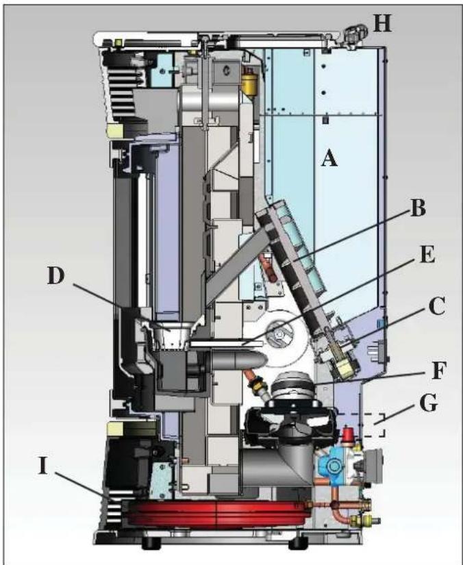
The fuel tank (A) is located at the rear of the boiler-stove. Filling the tank is through the back of the lid at the rear of the top. The fuel (pellets) is taken from the storage tank (A) and, via an Archimedes' screw (B) activated by a gear motor (C) it is then transported to the combustion crucible (D).
The ignition of the pellet is via air heated by an electrical heating element (E) and is sucked into the crucible by a smoke extractor (F).
The combustion air is drawn into the room (where there must be an air intake) smoke extractor (F).
The smoke produced by combustion, is extracted from the boiler-stove through the smoke extractor (F), and expelled from the pipe union (G) located in the bottom portion of the rear of the boilerstove.
The ash falls under and beside the crucible in which is housed an ash tray from which the ash must be periodically removed by vacuuming when cool.
The hot water produced by the boiler-stove is transferred via a circulator built into the boiler-stove itself, to the heating system circuit.
The boiler-stove is designed to function with closed expansion tank (I) and pressure valve, both of which are built in.
Fuel quantity, smoke extraction/combustion air supply and pump activation are regulated by the control board which is equipped with Leonardo software to achieve high combustion efficiency and low emissions.
The synoptic panel (H) is installed on the top, through which all phases of operation can be displayed and controlled.
The main phases can even be handled by remote control.
A serial port is found at the back of the boiler-stove (optional cable: code 621240) to be connected to devices that allow remote ignition (e.g. remote telephone, local thermostat).
Operating modes
(for further details, please see page 47)
The temperature of the water required in the system is set via the panel (standard recommendation 70^ ) and the boiler manually or automatically modulates the power to maintain or reach this temperature.
The Eco function can be enabled in small systems (the boiler shuts down and goes on again according to the water temperature required).
FEATURES
- ELECTRONIC CIRCUIT BOARD
LEONARDO® is a combustion safety and control system which allows optimal performance in all conditions thanks to two sensors measuring the pressure level in the combustion chamber and smoke temperature.
The detection of and subsequent optimisation of these two parameters is continuous in order to correct operation anomalies in real time.
The LEONARDO® system offers constant combustion, automatically regulating the draft based on the characteristics of the chimney flue (bends, length, shape, diameter, etc.) and environmental conditions (wind, humidity, atmospheric pressure, installations at high altitude, etc.).
The standards for installation must be respected. LEONARDO® system is also able to recognise the type of pellets and automatically djust the flow moment by moment to ensure the required level of combustion.

ELECTRONIC CIRCUIT BOARD
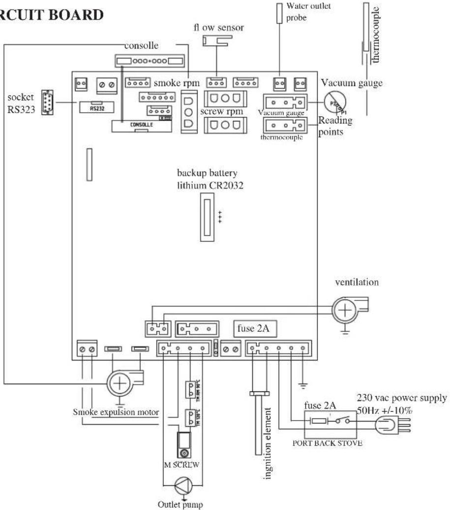
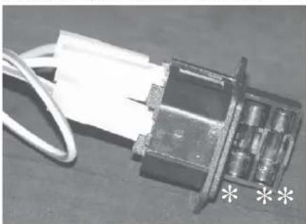
FUSE two fuses are inserted in the socket with switch, located on the back of the boiler-stove, one of which operational (^) and the other is held in reserve (^*) .
SERIAL PORT
The Dealer can install an optional on the AUX outlet for controlling the process of switching on and off (e.g. telephone remote, local thermostat), located at the rear oh the boiler-stove. Can be connected via special optional trestle (code 640560).
BACKUP BATTERY
A backup battery is found on the control board (3-Volt CR 2032 battery). Its malfunction is indicated with the following messages (not considered a defect but due to normal wear-and-tear): "Battery check". For more detailed information, please contact the DEALER who has performed the first 1st ignition.
FEATURES
- EXTERNAL FINISHES
BIJOUX
off-white ceramic sides, top and inserts red ceramic sides, top and inserts
TRESOR
steel sides, grey ceramic top and inserts steel sides, off-white ceramic top and inserts steel sides, red ceramic top and inserts
STRASS
soapstone sides, top and inserts
CAMEO
sandstone sides, top and inserts
DIMENSIONI
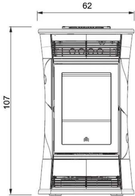
FRONT
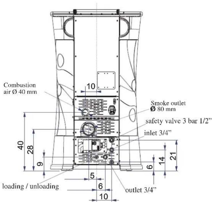
BACK
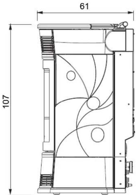
SIDE
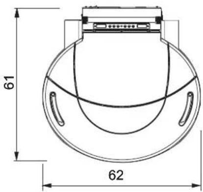
SYSTEM
FEATURES
| TECHNICALAND HEATING SPECIFICATIONS | ||
| Rated power | 15 | kW |
| Water heating power | 12 | kW |
| Approx. overall effi ciency | 91,6 | % |
| CO emission (13% O2) | 0,010 | % |
| Max. pressure | 3 | bar |
| Operating pressure | 1,5 | bar |
| Smoke output temperature from test EN 4785/303/5 | 129 | °C |
| Minimum draught | 12 / 5 | Pa |
| Min./max. autonomy | 5 / 18 | hores |
| Fuel consumption min./max. | 1 / 3,4 | kg/h |
| Hopper capacity | 21 | kg |
| Heating capacity | 390 | m3 |
| Weight including packing BIJOUX / TRESOR / STRASS / CAMEO | 246 / 240 / 258 / 248 | kg |
| Diameter of smoke extract duct male thread (male) | 80 | mm |
| Air intake pipe diameter (male) | 40 | mm |
- The heatable room dimensions are calculated on the basis home insulation in compliance with Italian law 10/91, and subsequent changes together with an expected heat output of 33Kcal/m^3 per hour.
| ELECTRICAL CHARACTERISTICS | |
| Power supply 230Vac +/- 10% 50 Hz | |
| On/off switch yes | |
| Average power consumption | 100 W |
| Power consumption during ignition 400 W | |
| Remote control frequency Infrared | |
| Protection on mains power supply (see page 33) Fuse 2AT, 250 Vac 5x20 | |
| Protection on electronic circuit board Fuse 2AT, 250 Vac 5x20 | |
N.B.
1) keep in mind that external devices can cause interference to the operation of the circuit board.
2) caution: live parts. Servicing and/or inspections must be carried out by qualified staff.
(Before carrying out any maintenance, disconnect the device from the mains power supply)
The data shown above is purely indicative.
EDILKAMIN s.p.a. reserves the right to change the products at its discretion without notice.
FEATURES
COMPONENTS - SAFETY AND DETECTION DEVICES
Smoke thermocouple
on the smoke outlet. It reads the smoke temperature. It regulates the ignition stage and shuts the boiler-fireplace down if the temperature is too high or too low.
Flow sensor
located in the extraction duct, is activated and shuts down the thermo stove when the flow of combustion air is incorrect, which means a resulting risk of low pressure problems in the smoke circuit.
Feed Screw safety thermostat
Placed near the pellet hopper. It disconnects the electrical supply to the gear motor if the temperature detected is too high.
Water temperature detector
It reads the water temperature in the boiler and sends the circuit board information for pump management and boiler power modulation.
If the temperature is too high, it starts a shutdown.
Water overheating safety thermostat
detects the water temperature in the thermo-stoves. If this is too high, it triggers the shutdown process by disconnecting the electrical supply to the gear motor.
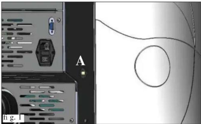
If the thermostat has been activated, it must be reset by pushing the red emergency button located on the left hand side of the thermo stove (A -fi g. 1).
Overpressure valve 3 bar
Upon reaching the pressure stipulated on the plate, the system is triggered to discharge the water and consequently the water must be topped up.
WARNING!!! remember to carry out the connection with the sewage system.
Electric coil
It sets off of the combustion of the pellets and it remains lit until the flame has been ignited. This component is subject to wear.
Smoke extractor
"Pushes" the smoke into the flue and draws out combustion air via a vacuum.
Vacuum gauge (electronic pressure sensor):
positioned on the smoke extractor, which detects the vacuum value (compared to the installation environment) in the combustion chamber.
Tank safety thermostat:
Located on the system that loads the pellets from the hopper. Trips when the temperature inside the boiler-stove is too high. It stops pellet loading, causing the boiler-stove to go out.
Pump (circulator)
"Pushes" water toward the heating system.
Closed expansion tank
absorbs" the variations in the volume of water contained inside the boiler-stove due to the heating effect.
Aheating technician must evaluate the need to add a second tank to the existing one, depending on total amount of water in the system.
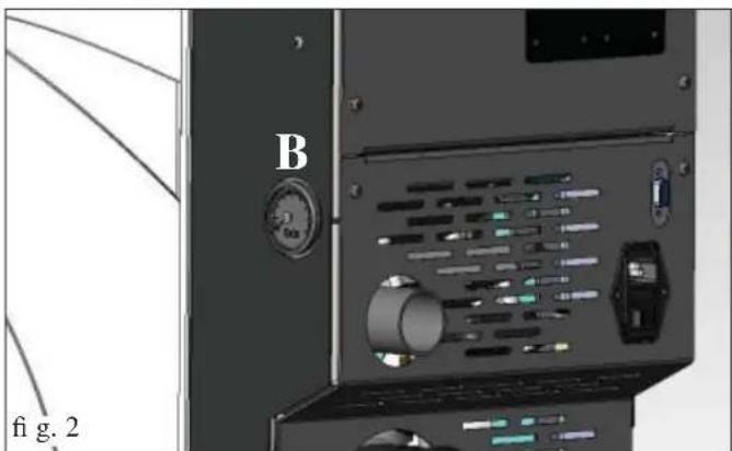
Manometer
It is located on the right side of the thermo stove (B -fig. 2), and is used to read the water pressure.
When the thermo stove is running, the recommended pressure is 1,5 bar.
Drain tap
positioned on the back of the thermo stove, low down. It must be opened if the water the unit contains needs to be drained.
Venting valve:
positioned in the upper part (see page 46), it allows for the "bleeding" of any air present during the loading of water inside the boiler-stove.
The plumbing connection must be formed by qualified personnel that are able to issue a declaration of conformity in terms of Ministerial Decree 37 ex Law 46/90.
All local and national laws and European standards must be met when installing and using the appliance. In Italy, refer to the UNI 10683 standard, as well as any regional or local health authority regulations
However, it is essential that reference be made to current laws in the individual countries. If installing in an apartment building, check with the management company first.
VERIFY COMPATIBILITY WITH OTHER DEVICES
The thermo stove MUST NOT be installed in the same space as that used to house type B gas hearing units (e.g. gas boilers, stoves and equipment served by an extraction hood) as the thermo stove may cause a low pressure area in the space, compromising how this equipment operates or be influenced by the same.
VERIFYTHE POWER SUPPLY
CONNECTION (the plug must be accessible)
The boiler-stove is supplied with a power cable that is to be connected to a 230V50Hz socket, preferably fitted with a magnetothermic switch.
The electrical system must comply with the law; particularly verify the efficiency of the earthing system.
The power line must have a suitable cross-section for the boiler power.
An inadequate earthing system can cause anomalies for which Edilkamin cannot be held liable.
FIRE SAFETY DISTANCES AND LOCATION
For correct operation the boiler must be level.
Check the load-bearing capacity of the floor.
The boiler must be installed in compliance with the following safety conditions:
-
medium flammability items must be kept at a minimum distance of 20cm from the sides and back of the boiler-stove
-
highly flammable items must be kept at a minimum distance of 80~cm if placed in front of the boiler-stove
-
if the boiler-stove is installed on a flammable floor, a sheet of heat insulating material must be placed between the boiler-stove and the floor, which protrudes by at least 20cm at the sides and 40cm at the front.
Flammable objects must not be placed above the boiler or at a distance that is any less than the stipulated safety distances.
If connected to wooden walls or other flammable materials, the smoke exhaust pipe must be appropriately insulated with ceramic fi bre or other similar material.
AIR INLET (to be mandatorily implemented)
The room where the stove is located must have an air intake with cross section of at least 80cm^2 to ensure replenishment of the air consumed by combustion. Alternatively, the stove air may be taken directly from outside through a 4cm steel extension of the pipe.
In this case, there may be condensation problems and it is necessary to protect the air intake with a grille, which must have a freesection of at least 12cm^2
The pipe must be less than 1 metre long and have no bends. It must end with section at 90^ facing downwards or be fitted with a wind guard. In any case all the way air intake duct must be a free section of at least 12cm^2
The external terminal of the air inlet channel must be protected with an anti-insect netting that does not reduce the 12cm^2 through passage.
SMOKE OUTLET
The boiler-stove must have its own smoke outlet (the smoke cannot be discharged into a smoke flue used by other devices).
The smoke is discharged through the 8cm diameter outlet at the back of the boiler. A T-junction must be set up with a condensation collection stopper at the beginning of the vertical section. The smoke outlet must be connected to outside by means of suitable steel pipes EN 1856 certifi ed.
The pipe must be hermetically sealed. The material used to seal and if necessary insulate the pipes, must be resistant to high temperatures (high temperature silicone or mastic).
The only horizontal section allowed may be up to 2m long. It may have up to three 90^ bends.
If the outlet is not fitted into a chimney flue, a vertical section and a wind guard are required (reference UNI 10683).
The vertical duct can be internal or external.
If the smoke channel (part of the pipe that goes from the boiler-stove to the chimney flue) is outside, it must be appropriately insulated. If the smoke channel is fitted inside a chimney flue, the latter must be suitable for solid fuel.
If it is wider than 150mm in diameter it must be improved by entering a pipe that has a suitable cross-section and is made of suitable material (e.g. 80mm diameter steel).
All sections of the smoke duct must be accessible for inspection. If it is not removable, it must have inspection holes to allow for cleaning.
The thermo stove is designed to operate under any weather conditions.
In the case of particularconditions, such as strong winds, safety systems may intervene that extinguish the thermo stove. In this case, do not operate the appliance while the safety devices are disabled. If the problem persists, contact the Service Centre.
TYPICAL EXAMPLES
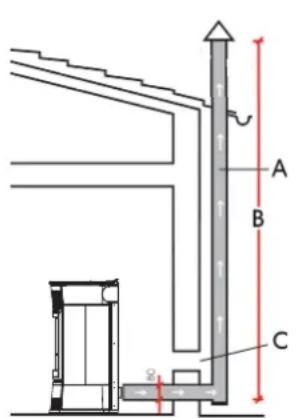
Fig. 1
Fig.
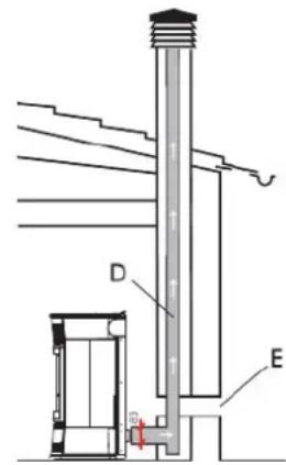
A: insulated steel chimney flu, Insulated
B: minimum height 1.5m and however beyond the eaves of the roof C-E: air intake from outside (through section at least 80~cm^2
D: steel chimney flue inside existing masonry chimney flue
CHIMNEY POT
The main characteristics are:
- an internal cross-section at the base, which is the same as that of the chimney flue
- an outlet cross-section which is no smaller than twice that of the chimney flue
- its position must be high enough to catch the wind and avoid downdraft areas in turbulent wind.
INSTALLATION
HYDRAULIC CONNECTIONS:
HEATING SYSTEM WITH THE THERMO STOVE AS THE ONLY HEAT SOURCE
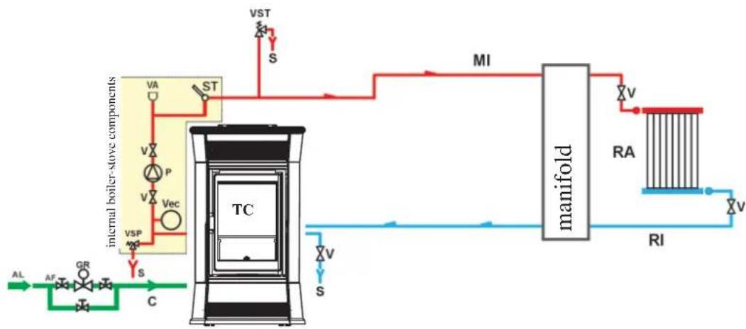
LEGEND
AF: Cold Water
AL: Water supply
C: Filling/Topping up
GR: Filling unit
MI: Outlet to system
P: Pump (circulator)
RA: Radiators
RI: Inlet from system
S:Drain
ST: Temperature Detector
TC: Boiler-stove
V: Ball valve
VA: Automatic bleed valve
Vec: Closed Expansion Tank
VSP: Safety Pressure Valve
VST: High Temperature
nage Valve
HEATING SYSTEM WITH THE THERMO STOVE COMBINED WITH A BOILER
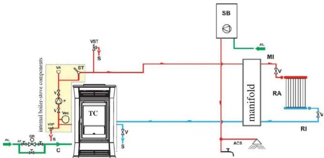
LEGEND
ACS: Household hot water
AF: Cold water
AL: Water supply input
C: Fill/Top up
GR: Pressure reducer
MI: System in
P: Pump (circulation)
RA: Radiators
RI: System return
S:Drain
SB: Water boiler
ST: Temperature probe
TC: Boiler-stove
V: Spherical valve
VA: Automatic air vent
Vex: Closed surge tank
VSP: Safety valve
VST: Thermal discharge valve
HEATING SYSTEM WITH THE THERMO STOVE AS THE ONLY SOURCE OF HEAT, WITH SANITARY HOT WATER BEING PRODUCED BY A BOILER
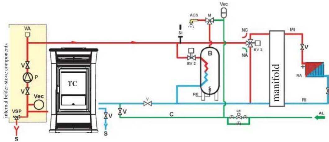
LEGEND
ACS: Household hot water
AL: Water supply input
B:Boiler
C: Fill/Top up
EV2: 2-way electro-valve
EV3: 3-way electro-valve
NA: Normally Open
NC: Normally Closed
GR: Pressure reducer
MI: System in
P: Pump (circulation)
RA: Radiator
RI: System return
S:Drain
TC: Boiler-stove
V: Spherical valve
Vcc: Closed surge tank
VSP: Safety valve
This layout is purely indicative. Have a plumber design and install the system.
ACCESSORIES:
In the diagrams referred to in the previous pages the use of accessories available from the Edilkamin catalogue has been assumed.
Individual spare parts are also available (exchanger, valves, etc). For information, please contact your local dealer.
COVERING INSTALLATION BIJOUX
For proper assembly of the ceramics series on the boiler-stove, proceed as indicated in the sequence
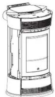
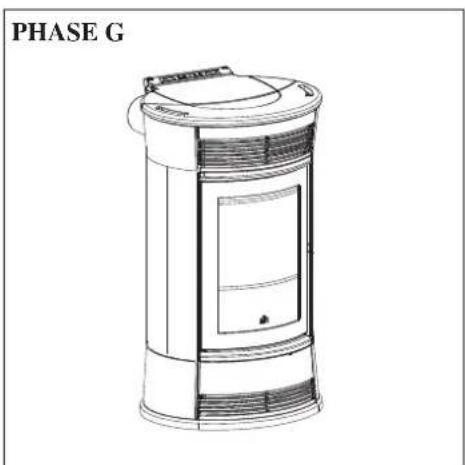
The stove as it is after unpacking.
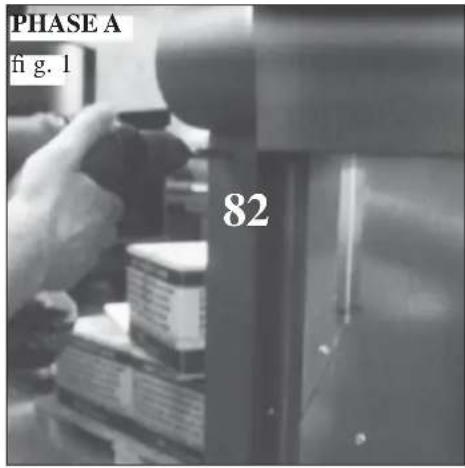
PHASE A
Fig. 1 Unscrew the screws to remove the two rear ceramic fastening profiles (82)
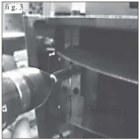
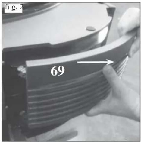
Fig. 2 Disassemble the upper front cast iron grille (69) assembled fitted into place on the boiler-stove.
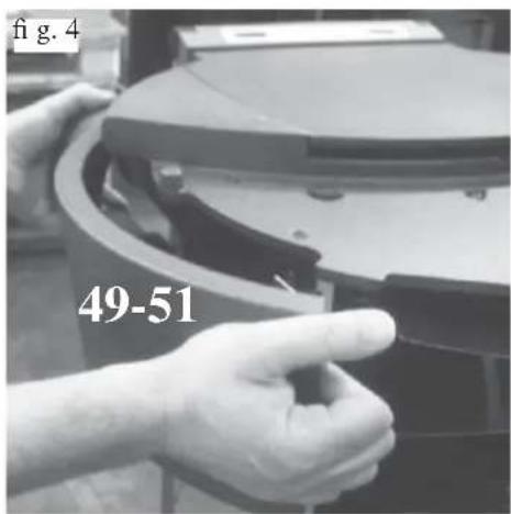
Fig. 3-4 Unscrew the screws (fig. 3) to remove the upper side front cast iron panels on the right and left sides (51 - 49)
PHASE B
fi g.6
f1g.7
PHASE B
RIGHT SIDE CERAMIC PANEL ASSEMBLY (HANDLE SIDE):
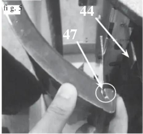
Fig. 5
- Open the hearth door
- Align the apertures present on the front part of the ceramic panel (47) to the fastening brackets (44) located on the structure (fi g. 5).
- Insert the ceramic panel in the brackets
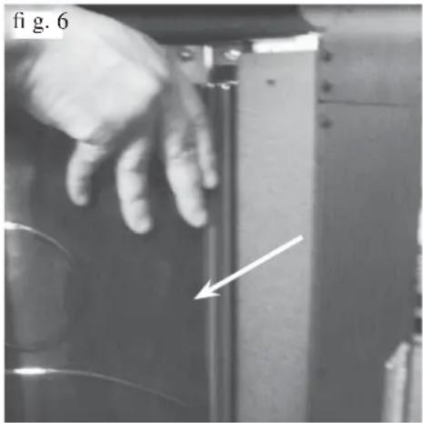
Fig. 6
- Rest the rear part of the ceramic panel on the galvanised side of the boiler-stove and back on the rear ceramic fastening profil e.
- Close the hearth door.
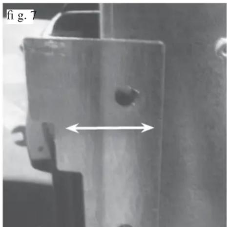
Fig. 7
- Check that there is enough usable space between the side ceramic panel and the hearth door to permit easy opening with the handle, and if there is no such space, disassemble the ceramic panel and adjust as follows:
- loosen the upper bracket and lower bracket screws
- adjust the brackets "just enough"
-
tighten the bracket stop screws
-
Reassemble the ceramic panel according to the sequence from points 5 to 6; once suitable ideal space is reached between the ceramic panel and the hearth door, complete assembly sequence.
-
Reposition the upper side cast iron front panel (51)
- Reposition the rear fastening ceramic right profile (82)
Note: silicone pads have been supplied to be used for any alignments between the ceramic panel and cast iron parts, where 3 pads are to be placed at an equal distance on the base of the lower cast iron front panel.
LEFT SIDE CERAMIC PANEL ASSEMBLY:
Fig. 5
- Keep the hearth door closed
- Align the apertures present on the front part of the ceramic panel (47) to the fastening brackets (44) located on the structure.
- Insert the ceramic panel in the brackets
Fig. 6
- Rest the rear part of the ceramic panel on the galvanised side of the boiler-stove and back on the rear ceramic fastening profilc.
Fig. 7
If necessary, adjust the fastening brackets as per point 9
- Reposition the upper side cast iron front panel (49)
- Reposition the rear fastening ceramic right profile (82)
Note: silicone pads have been supplied to be used for any alignments between the ceramic panel and cast iron parts, where 3 pads are to be placed at an equal distance on the base of the lower cast iron front panel
COVERING INSTALLATION BIJOUX
PHASE C
PHASED

PHASESE6
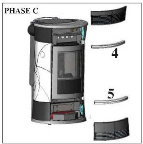
PHASE C
CERAMIC FRONT PANEL ASSEMBLY:
- Line up the holes in the upper ceramic front panel (53) with the corresponding holes in the front grille (69).
- In order to fasten the upper ceramic front panel (53) to the upper front grille (69), insert the knurled washer onto the thread of the pin and tighten it manually (without the use of any tools).
- Assemble the grille including the ceramic panel to the boiler-stove, putting suitable pressure to hook it on to the stop springs
Remove the lower front cast iron grille (52) by applying suitable pressure to release it from the special locking springs.
- Line up the holes in the lower ceramic front panel (53) with the corresponding holes in the front grille (69).
- In order to fasten the lower ceramic front panel (53) to the lower front grille (69), insert the knurled washer onto the thread of the pin and tighten it manually (without the use of any tools).
- Assemble the grille including the ceramic panel to the boiler-stove and screw in the previously removed grille stop screws.
PHASED
CERAMIC TOP ASSEMBLY:
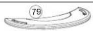
- Place the ceramic top (79) over the cast iron boiler-stove top
- If the ceramic top proves unstable, remove it
- Stability of the ceramic top is to be carried out, where necessary, using the provided washer between the pad and the cast iron top
- Reposition the ceramic top
PHASE E
- The boiler-stove is now ready to be positioned.
BIJOUX COVERING DISASSEMBLY
For proper disassembly of the ceramic series proceed as follows:
PHASE A
- Remove the ceramic top (1).
PHASE B/C
DISASSEMBLING THE CERAMIC FRONT PLATES:
- Remove the upper grille (2) and lower grille (3) by applying suitable pressure to release them from the special locking springs.
- Remove the ceramic front panels (4-5) by removing the milled sealing washers.
PHASED
DISASSEMBLY RIGHT SIDE CERAMIC (HANDLE):
- Open the door.
- Remove the rear profile (6) by unscrewing the fastening screws.
- Remove the ceramic (7) disengaging it from the holding brackets.
Close the door.
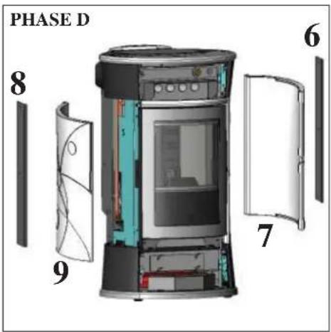
DISASSEMBLY LEFT SIDE CERAMIC:
- Keep the door closed.
- Remove the rear profile (8) by unscrewing the fastening screws.
- Remove the ceramic (9) disengaging it from the holding brackets.
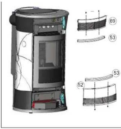
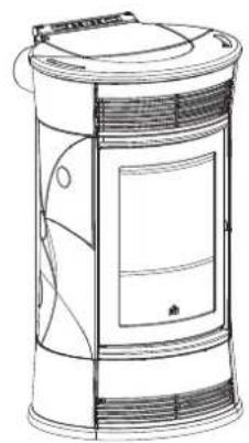
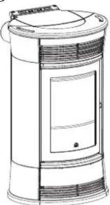
COVERING INSTALLATION TRESOR
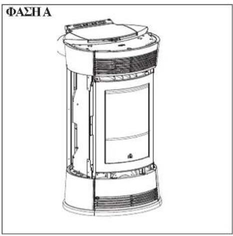
PHASE A
PHASE A
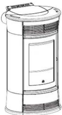
- This phase presents the boiler-stove after being unpacked and positioned in the room
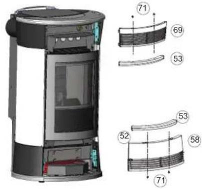
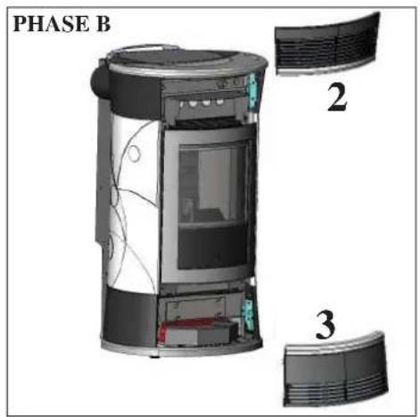
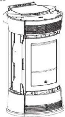
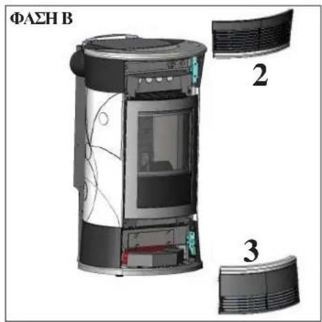
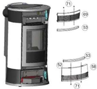
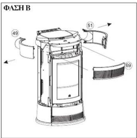
PHASE B
PHASE B
- Remove the cast iron front panels (69 -52) that are slotted in, then with the screws (71) provided, mount the ceramic front panels (53) onto the cast iron panels (69 - 52), and reposition them.
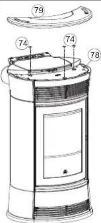
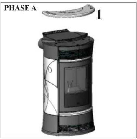
PHASE C
PHASE C
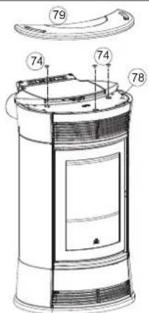
- Position the cast iron top (78), the three pads (74) in their housing, then place the ceramic top (79) over.
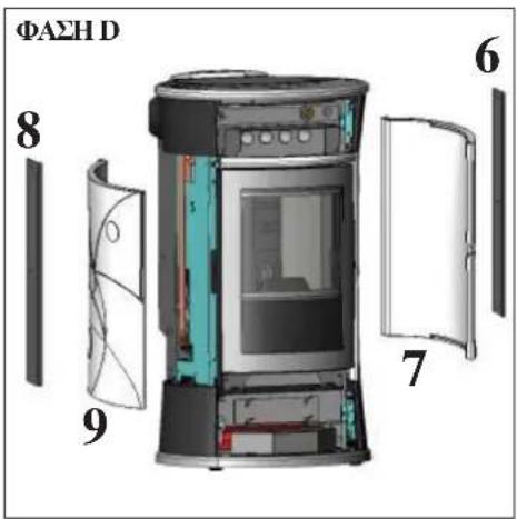
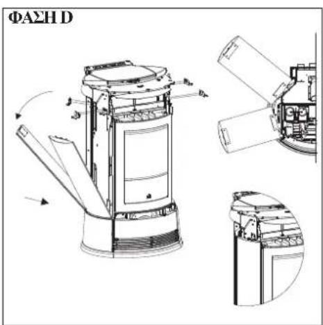
PHASE D
PHASED
- The boiler-stove is now ready to be positioned.
COVERING INSTALLATION STRASS/CAMEO
PHASE A
PHASE A
This phase presents the boiler-stove after being unpacked and positioned in the room
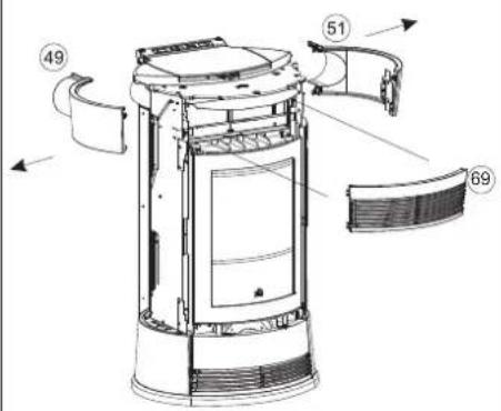
PHASE B
PHASE B
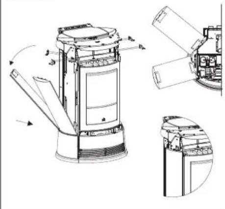
- Remove the front panel (69) to remove the two screws holding the upper right (51) and left (49) cast iron front panels
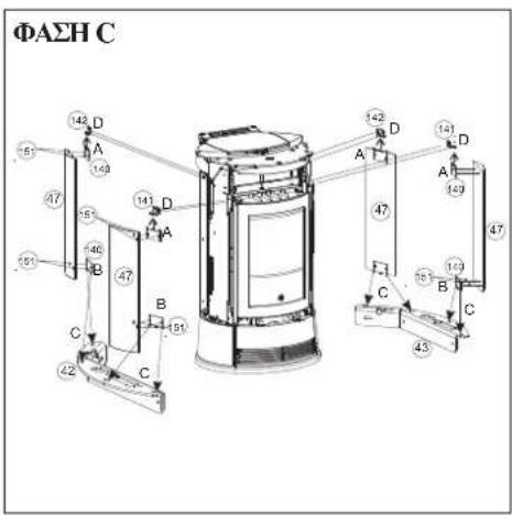
PHASE C
PHASE C/D
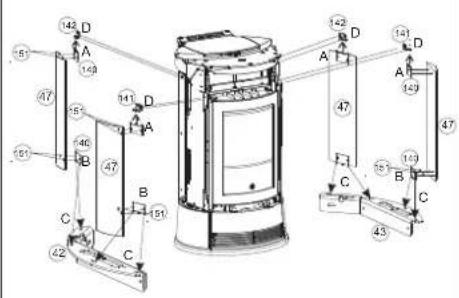
- Assemble the plates (140) to the stone sides "A-B" (47) with TE M 6x12 screws supplied and point in the 4.2 × 9.5 self-tapping screws without tightening them to the two front and rear locking brackets (141-142-152-153) to the structure.
- Now insert the stone side (47), first inserting it in the rear part "C" and then turning it and resting it on the upper part, fitting it in the front bracket "D" (141-152).
- Now tighten screws, which were previously pointed in, on the front and rear locking brackets (141-142-152-153).
PHASED
Note:
During the assembly phase of the stone series, check that the stones are aligned with the cast iron top. If they are not, or rather they are within a few mm, a flat washer must be placed between the side stone and the centring bracket (151) to compensate for the indentation of the coating.
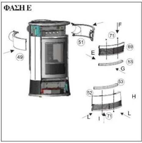
COVERING INSTALLATION STRASS/CAMEO
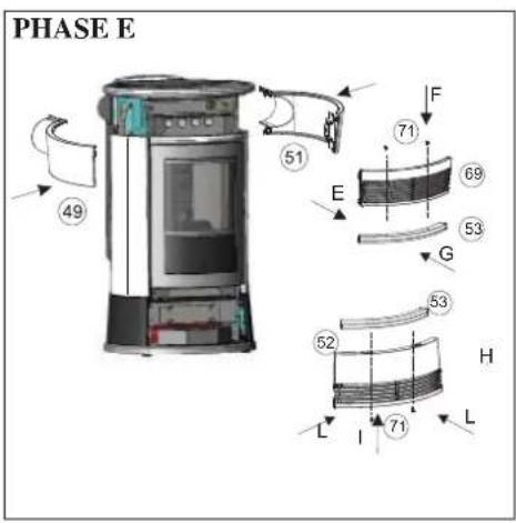
PHASE E
- Using the screws (71) and washers (151) supplied, mount the cast iron front panel (53) onto the upper front panel (69) and reposition it "G".
- Remove the lower front panel "H" (52)
- Using the screws (71) and washers (151) supplied, mount the cast iron front panel (53) onto the lower front panel (52) and reposition it in housing "T".
- Replace the two upper right (51) and left (49) front panels and screw the front with the previously removed screws.
- Position the front grille (69) by pressing
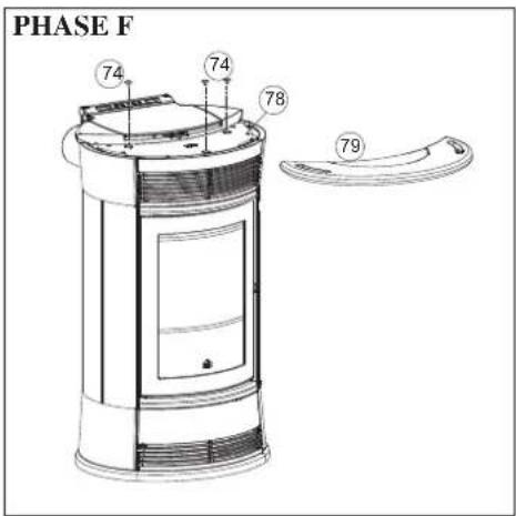
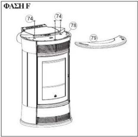
PHASE F
- Position the cast iron top (78), the three pads (74) in their housing, then place the stone top (79) over.
PHASE G
- The boiler-stove is now ready to be positioned.
INSTRUCTIONS FOR USE
1st ignition/test by the Edilkamin authorised Dealer
Commissioning must be done as laid down in the UNI 10683. This standard indicates the control operations to be carried out in situ, aimed at ascertaining correct system function.
Edilkamin's Technical Assistance staff (CAT) will also calibrate the boiler-stove based on the pellet type used and the installation conditions.
Edilkamin's Technical Assistance staff (CAT) must commission the boiler in order for the guarantee to be activated.
The DEALER must also:
- Verify that the hydraulic system is correctly installed and is equipped with an expansion tank that is sufficiently large to guarantee safety.
The presence of a tank within the boiler-stove does NOT guarantee appropriate protection from thermal expansion occurring in the whole system.
Therefore the installer must assess whether an additional expansion tank is needed, depending on the type of system installed.
- Connect the electrical power to the boiler and implement a cold test (to be carried out by the DEALER).
- Fill the system using the filling tap (it is recommended not to exceed a pressure of 1,5 bar).
When flling, 'bleed' the pump and the relief tap.
There may be a slight smell of paint the first few times it is ignited, however, this will disappear quickly.
Before igniting you must check:
- that installation is correct
the power supply - that the door closes properly to a perfect seal
- that the combustion chamber is clean
- that the display is on stand-by (time and temperature set).
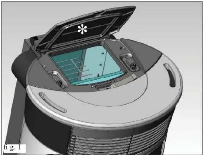
FILLING THE PELLET HOPPER
the hopper lid opens and closes with a practical click-clack system. simply apply slight pressure to the front part of the cast iron lid * (fi g. 1-2).
ATTENTION:
Use the glove supplied when filling the stove whilst it is running and therefore is hot.
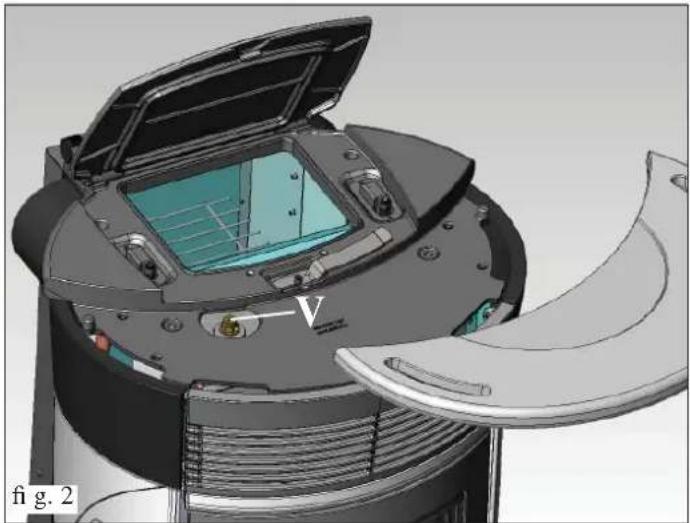
ATTENTION:
When igniting for the first time, do an air/water purge using the manual valve (V) on the front of the top.
The operation must be repeated during the first days of use and in the event the plant has only been partially reloaded.
The presence of air in the ducts does not allow for proper operation.
To facilitate venting operations, the valve is fitted with rubber hoses.
NOTE regarding the fuel.
Boiler-stove is designed and programmed to burn wood pellets with 6mm diameter. Pellets are a type of fuel in the form of little cylinders, made from compacted sawdust, compressed under high pressure with no adhesives or foreign materials. They are sold in bags of 15kg .
For the boiler to function properly, you MUST NOT burn anything else in it. Using other materials (including wood) will render the warranty null and void. Such use is detected by laboratory analyses.
Edilkamin has designed, tested and programmed their boiler-stoves to guarantee the best performance when pellets with the following characteristics are used:
-diameter:6 millimetres
- maximum length: 40 mm
maximum moisture content: 8%
-calorificvalue:atleast4300
If pellets with different characteristics are used, the boiler-stoves must be recalibrated - a similar procedure to that carried out by the DEALER when the boiler is ignited the first time. Using unsuitable pellets may: decrease efficiency; cause malfunctions; stop the boiler-stove from functioning due to clogging, dirt on the glass, unburnt fuel, etc.
A simple, visual analysis of the pellets may be carried out:
Good quality: smooth, uniform length, not very dusty.
Poor quality: with longitudinal and transverse cracks, very dusty, various lengths and mixed with foreign matter.
INSTRUCTIONS FOR USE
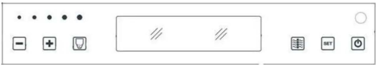
Mimic panel

bottom 0/1: to turn on and off (hold down for 2^ ) and to exit from the menu during programming

Pressing briefly displays the set temperature and the working temperature; holding it down (hold for 2") allows you to access various programming menus.

to increase the various settings

to decrease the various settings; pressing for 5s locks the keypad, pressing for another 5s unlocks the keypad

Each time you press informs the memory of the electronic board that has been inserted into the 15Kg tank; a constant pressure of 5"deletes Kg residues or those previously entered

(ventilation button) sets the operation of the fan as follows:
- Air OFF: no ventilation; the stove channels all the power to the water
- Air AUTO: ventilation is optimised by an automatic programme
- Air MAN 1-2-3-4-5: ventilation is chosen manually by the user using the slider-led
1
2
1
Tap on the LED points to select the desired fan speed environment
Filling the feed screw
If the pellet storage tank is completely emptied, it follows that the Archimedes' screw is also emptied.
Before restarting the stove you must fill it by following these steps: press the +/- keys simultaneously (via the remote control or the synoptic panel) for a few seconds, after which, having released the keys, the display will show the text "Reload".
It is quite normal for some pellet residue to remain inside the hopper, this is what the feed screw is unable to pick up.
Once a month, fully vacuum the hopper to prevent dusty residue from accumulating.
Automatic ignition
With the boiler-stove on stand-by, press the 0/1 button for 2 seconds (on the synoptic panel or remote control).
This will start-up the ignition process, 'Start-up' will appear on the display and a countdown will commence in seconds (1020).
There is no preset time for the ignition process: its duration will be automatically shortened if the control board detects that certain tests have been carried out positively.
The fl ame appears after about 5 minutes.
Manual ignition (in case of start up failure)
At a temperature lower than 3^ - too low for the electrical resistance to become red hot - or if the resistance is temporarily not working, you can use a firefighter to ignite the boiler-stove. Insert a well-lit firefighter into the combustion chamber, close the door and press 0/1 on the synoptic panel or remote control.
Operating modes
Operating from synoptic panel/remote control.
With the boiler-stove running or on stand-by, from the synoptic panel.
Press the + or - keys to increase or decrease the desired water temperature.
- Pressing the ventilation button causes the cyclic rotation of the 3 different settings of the stove's internal ventilation system (Air display).
You can turn the ventilation off (OFF), make it work in automatic mode (AUTO) or manually select the desired speed (MAN: 1-2-3-4-5).
In either case (automatic or manual), ventilation is activated when the stove is operational and automatically deactivates when the stove is on stand-by.
INSTRUCTIONS FOR USE
Shutdown
While the boiler-stove is working pressing the 0/1 key for 2 seconds begins the shutdown process and "STOPPING" is displayed (for 10 minutes). The turning off phase includes:
- The interruption of falling pellets
- The circulation of running water.
- Smoke extractor operating at maximum speed.
Air ventilation
Never pull the plug during shutdown.
N.B. Please note that the circulator runs until the water temperature drops below 40^ .
Setting the clock
Press the MENU button for 2 seconds and use the + and - keys to follow the instructions given on the display to access the 'Clock' menu. This allows you to set the time on the electronic control board. Then press MENU and the following data appears in sequence - this can be adjusted: day, month, year, hour, minutes, day of the week. When 'Save?' appears on the display, you can check that the settings have been entered correctly before confirming. Press MENU to save the information ('Save OK' then appears on the display).
Programmer to ignite and shutdown the thermal stove at various times during the week.
Press the MENU button on the remote control or the synoptic panel for 2 seconds to access the time setting function and press the + key to access the weekly timer function 'Program ON/OFF' will appear on the display. The timer allows you to set a number of ignitions and shutdowns per day (up to a maximum of three), for each day of the week. As you confirm via the MENU button, one of the following options will appear:
-
No Prog. (no program is set)
-
Program/daily (a single program is set for every day)
-
Program/weekly (a program is set for each day of the week)
Move from one to the other using the + and - keys.
Use the MENU button to confirm the 'Daily program' option and access the selection of the number of programs (ignition/shutdown) to be set per day. Use the 'Program/daily' option to set the identical program/s for every day of the week.
The following will be displayed if the + key is pressed:
- No Prog.
-Prog.No.1 (one ignition and one shutdown per day),Prog.
No. 2 (same as before), Prog. No. 3 (same as before)
Use the button to show them in reverse order. If the 1st program is selected, the ignition time is shown.
The display shows: 1 Ignition Hour 10.30; use the + / - keys to change the hour and press MENU to confirm.
The display shows: 1 Ignition Minutes 10.30; use the + / - keys to change the minutes and press MENU to confirm.
In the same way, adjust the shutdown times.
The program is confirmed by pressing the MENU button when "Saved" appears on the display.
When confirming 'Program/week', you will need to choose the day to which the program is to apply:
1 Mon; 2 Tues; 3 Wed; 4 Thurs; 5 Fri; 6 Sat; 7 Sun
Once you have chosen the day by scrolling through them with the + and - keys, confirm by pressing MENU and proceed with the settings of the programs in the same way as for the 'Program/daily', selecting whether or not to enable a program for each day of the week and choosing the number and times of interventions.
Should you make a mistake whilst setting the programs you can exit without saving by pressing the 0/1 key and 'Saved' will appear on the display. Should the hopper run out of pellets, the boiler-stove will block and 'Stop/Flame' will appear.
Pellet reserve warning
The boiler-stove is equipped with an electronic pellet detection system.
The pellet detection system is integrated into the electronic control board, allowing the stove to monitor how many kilos of pellets are left.
This verification is implemented at any point whilst the stove is in operation mode.
For correct system operation, it is important that the following procedure is adhered with during the first ignition (that must be implemented by the DEALER). Before starting to use the pellet detection system, you must load and consume a full sack of pellets.
This allows for a brief running-in of the loading system.
Subsequently load 15kg of pellets.
Then press the 'reserve' button once, thereby storing the data into the memory that 15kg have been loaded.
From now on the display will show the remaining pellets as they decrease in kg (15...14...13). Each time pellets are reloaded you must
enter the quantity. E.g. when loading 15kg simply press the 'pellet load' button to enter this into the memory.
For other quantities, or in the event of an error, you can specify the quantity using the pellet reserve menu as follows:
Press the MENU button for 2 seconds to view the SETTINGS. Press + or - consecutively to view T. Max exit.
ConfirrmbypressingMENUandthememainingquantityofpelletswill be displayed ^+ thatbeingloaded(defaultis15andcan be changed using the + / - keys).
Press the + button to increase the kg value to be entered, press the -button to reduce the value, repeatedly press the -button to get 00kg load (R on the display), which allows deletion of the residual load.
Should the hopper run out of pellets, the boiler-stove will block and 'Stop/Flame' will appear.
Variation feeding pellets (ONLY AFTER SUGGESTED BY DEALER)
Press and hold the "M" key on the remote control for two seconds. Scroll through the display instructions using the "+" and "-" keys, to the description "ADJ-PELLET". By confirming this function using the menu key you can adjust the supply of pellets,
by reducing the set value, you decrease the supply of pellets, increasing the set value increases the supply of pellets. This function can be useful in the event that one changes the type of pellets used, no longer using those for which the boiler-stove was calibrated, thus necessitating an adjustment of the load setting.
INSTRUCTIONS FOR USE
Should this correction not suffice, contact the Edilkamin-authorised Dealer, to establish the new operating axis.
Notes on flame variability: Any changes in the state of the flame depend on the type of pellets used, as well as on normal variation of solid fuel flames and on the periodic cleaning of the crucible the boiler-stove automatically carries out (Note: This does NOT replace the necessity cold vacuuming by the user prior to start up).
Environmental temperature control
this comfortable and simple adjustment feature, as standard in this line of products, allows you to manage the stove power based on the environmental temperature.
After activating the "Comfort Clima" function from the parameters menu (ask the technical assistance centre - TAC), press the SET button briefly a couple of times to switch from classic "Modulate_Power" mode to "Comfort Clima" mode; then select the desired mode from the display.
Modulate power mode
the stove modulates its power by following the output temperature set by the user.
Comfort Clima mode
the stove modulates its power by following the output temperature set by the user. You can also use the remote control as a room thermostat: on reaching the set temperature the stove will go to minimum power.
Setting the environmental temperature
In "Comfort Clima" mode, by pressing the + / - buttons on the synoptic panel or on the remote control, you can set the display to the desired environmental temperature.
-At environmental temperatures below the set temperature, the stove modulates power normally to reach the set output.
-With environmental temperature reached (+2^) the stove goes to minimum power.
The environmental temperature is transmitted from the remote control; the remote control transmitter must be visually aligned with the receiver of the synoptic panel
If the remote control is incorrectly positioned, it cannot send its recorded temperature. The stove therefore independently decides to operate at minimum power and continues thus until the connection with the remote is restored
Temperature control with external thermostat
another temperature control system is available as an alternative to the remote control. You can in fact connect the thermostat serial port to your home thermostat or any (clean output contact) easily available one
The stove will automatically recognise the connection with the thermostat serial port under the following conditions:
With environmental temperature lower than the thermostat setting (contact closed), the stove modulates power normally to reach the set temperature
-With environmental temperature reached by the thermostat (contact open), the stove goes to minimum power
| Confi guration | Temperature provided by the remote control | Temperature provided by external environmental thermostat | No adjustment (factory setting) |
| "Comfort Clima" parameter | ON ON ON | ||
| "SONDA IR" parameter | ON OFF ON | ||
| Connection to serial port | NO no connection | Yes with blue serial cable | NO no connection |
INSTRUCTIONS FOR USE
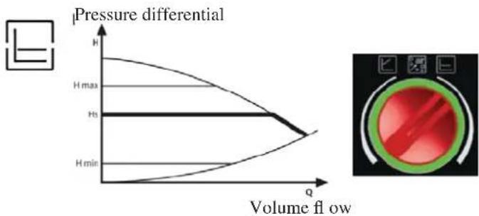
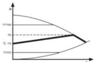
THE ELECTRONIC CIRCULATOR
The product you have purchased is equipped with a circulator with electronic motor.
Electronic control of operation:
a) Control mode p - c
In this mode, the electronic controller keeps the differential pressure generated by the pump at a constant set value of H s.
c) Venting procedure
This procedure allows the expulsion of air present in the hydraulic circuit. After manual selection of the "AIR" mode, the pump will automatically alternate between maximum and minimum speed for 10 minutes. At the end of the procedure, the circulator will go to the pre-set speed. You can then select the desired mode of operation


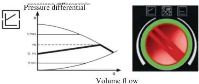
b) Control mode p - v
In this mode, the electronic controller varies the pressure
differential between the set value Hs and 1 / 2H s. The pressure
differential varies with the volume flow.
| LEDMEANINGWORK CONDITIONONCAUSERRESOLUTIVEACTION | ||||
| Green led on Working pump The pump works in base of its settings | Normally work | |||
| The green led flash quickly | Normally work | |||
| The led flash with light red/green | The pump is ready to work but doesn't turn | - undervoltage U < 160V overvoltage U > 253V - Engine temperature too high | - Check the voltage 195V < U < 253V - Check the water temperature | |
| The led flash with red light | Pump out of service The pump is stopped (blocked) The voltage doesn't receive the voltage | - The pump isn't connected on the motherboard - The led is defective - The pump is defective | - Check the wire connection - Check if the pump works - Change the pump | |
| Led off No supply | The pump doesn't receive the voltage | - The pump isn't connected on the motherboard - The led is defective - The pump is defective | - Check the wire connection - Check if the pump works - Change the pump | |
INSTRUCTIONS FOR USE
REMOTE CONTROL
This controls all the functions. It is necessary to point it directly at the boiler-stove.
For further information contact our customer service centre.

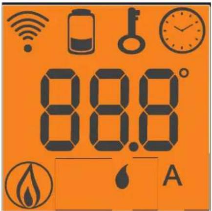
Key to buttons and display:
: ignition / shutdown button
+/- : to increase/decrease the various regulations
A : button to switch to the "EASY TIMER" program
M : key for viewing/setting the set temperature (Set 70^ )

Indicates data transmission between the remote control and the control board.

blocked keypad; avoid turning on the remote control for no reason (press "A" and "M" simultaneously for a few seconds to block/unblock the keypad)

low batteries; replace them and put them in their appropriate containers.

Indicates that ignition/shutdown is being via the "EASY TIMER" program
Indicates the room temperature detected by the remote control (it indicates the values of the set parameters during its technical set-up).

On icon: boiler-stove in start-up/operating phase

Indicates that the boiler-stove is operating in automatic mode

pellet/water boiler-stove remote control setting indicator
USING THE "EASY TIMER" PROGRAM

The new remote control allows you to manage a timer program that is very intuitive and easy to use:
- If the boiler-stove is on: a delayed shutdown can be set from the remote control - from one to twelve hours. The remaining time for the scheduled shutdown is shown on the display of the synoptic panel.
- If the boiler-stove is off: a delayed ignition can be set from the remote control - from one to twelve hours. The remaining time for the scheduled ignition is shown on the display of the synoptic panel.
- Setting: proceed as follows to set the timer:
a) Press the "A" button and the icon will light up on the display, thereby confirming the "Easy timer" program has been accessed.
b) Set the hours by pressing the + / - buttons, for example:

c) Point the remote control towards the synoptic panel receiver d) Confirm the setting by pressing the "A" button for a few seconds; the icon will go off and the remaining time will appear on the synoptic panel after which the "Easy timer" setting will intervene.
e) Repeat points a), b), c), d) to cancel the setting, and set the hours to "00H"
BLOCKED KEYPAD
The remote control buttons can be blocked so as to prevent it from going on accidentally.
Press the A and M buttons simultaneously and the key symbol will light up confirming that the keys have been blocked.
Press the A and M buttons simultaneously once again to unblock the keypad.
LOW BATTERY INDICATOR
When the battery icon lights up it indicates that the batteries inside the remote control are almost fl at.
Replace them with three new batteries of the same model (size AAA 1.5V).
- Do not use new batteries with used ones.
- Do not mix brands and different types as every type and brand has a different capacity.
- Do not mix traditional batteries with rechargeable ones;
- Do not try recharging alkaline and zinc-carbon batteries as this can cause them to break and/or a liquid leakage.
MAINTENANCE
Before performing any maintenance, disconnect the appliance from the mains.
Regular maintenance is required for the boiler-stove to function correctly.
The boiler-stove will trigger the message: 'smoke ^ C / high or 'Mainten.' to appear on the panel when further cleaning is necessary. This is preceded by Clean exchang. appearing on the display.
FAILURE TO PERFORM REGULAR MAINTENANCE, at least on a SEASONAL basis, could lead to poor functionality.
Any problems resulting from lack of maintenance will immediately void the warranty.
NOTE: The DEALER, upon commissioning, sets the kg value of consumed pellets; after which, the message "SERVICE UTE" will appear on the display. The boiler-stove continues operation, but the end client is invited to perform careful maintenance, described above and explained by the DEALER during commissioning, to the extent of his abilities. To eliminate the message from the display, press the ventilation button for at least 5 seconds after having completed maintenance.
N.B.
- Any unauthorised modification is forbidden
- Use spare parts recommended by the manufacturer
DAILY MAINTENANCE
Operations must be performed when the stove is off, cold and unplugged from the power supply.
Cleaning should be carried out with the aid of a vacuum cleaner (see optional page. 57), the whole procedure takes up a few minutes.
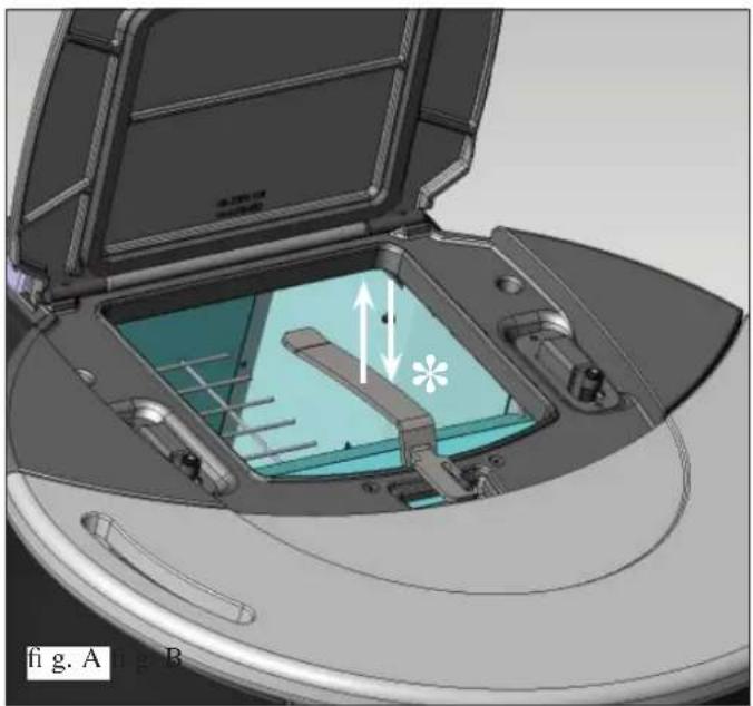
- THE CLEANING RODS (*) MUST BE AGITATED ONCE A DAY WITH THE GLOVE IN EQUIPMENT ALSO FREQUEN WHILE THE BOILER-STOVE IS IN FUNCTION) IN ORDER TO ALLOW FOR FUEL SAVINGS:
Shake the cleaning rod by the handle supplied, located towards the top on the front, below the tank cover (fig.A).
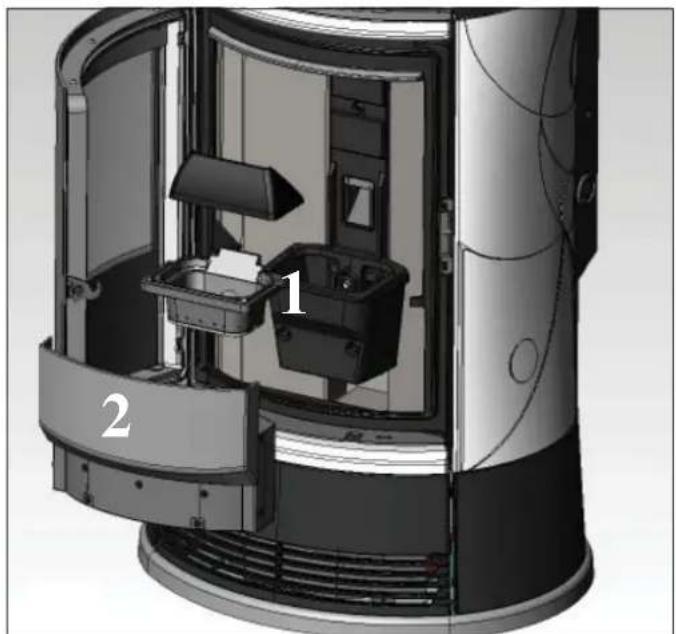
- Open the door, remove the combustion chamber (1 - fig. B) and empty the residue out into the ash pan.
- Scrap the combustion chamber with the spatula provided, removing any obstructions in the openings.
DO NOT EMPTY THE RESIDUE OUT INTO THE PELLET HOPPER.
- Take out and empty the ash (2 - fig B) pan into a fireproof container (the ash may still contain hot parts and/or embers).
- Remove the combustion chamber or use the spatula to scrape it and clean out any blocked holes on all sides
- Vacuum the combustion chamber holder, clean the edges where the combustion chamber is lodged into its seat.
- Clean the glass, if necessary (when cold).
NEVER SUCTION HOT ASH, as this could damage the suction device and possibly cause a fire.
ATTENTION: MAKE SURE THE ASH PAN IS CORRECTLY POSITIONED IN ITS HOUSING
WEEKLY MAINTENANCE
Clean the hearth (with the tube brush).
Vacuum the pipe near the electric coil.
MAINTENANCE
SEAS ONAL MAINTE NANCE (implemented by the DEALER)
Consists in:
Clean the stove internally and externally
- Carefully clean the heat exchange tubes
- Carefully clean and remove dirt from the combustion chamber and the relative compartment
- Clean fans, verify mechanical and clamp loosening
- Clean smoke channel (replace seals on smoke exhaust pipe)
Clean smoke duct
- Check the expansion tank
- Check and clean the circulator
Clean smoke extraction fan compartment.
- Clean smoke flow sensor.
- Clean smoke check thermocouple.
- Empty the pellet hopper and clean the base with the vacuum cleaner.
- Clean, inspect and scrape any residue from the ignition resistance compartment and if necessary, replace it
Clean/check the Synoptic Panel
- Visually inspect the electrical wires, connections and power cable
- Clean the pellet hopper and check loosening of the feed screw - gear motor assembly
- Replace the door seal
- Functionality test: load the feed screw, ignite, let it run for 10 minutes and shutdown
If the boiler-stove is used very often, it is recommended to clean the smoke channel every 3 months.
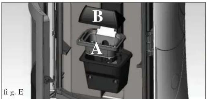
ATTENTION !!!
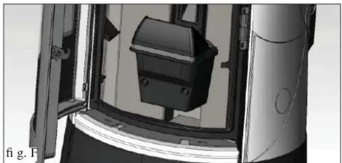
After implementing a normal cleaning procedure, INCORRE CT coupling of the upper (A) (figura E) and lower (B) (figura E) combustion chambers can compromise the boiler-stove's performance.
Before igniting the boiler-stove, make sure the combustion chambers are correctly paired as indicated in (fig. F) without ash or unburnt material present on the support perimeter.
We remind you that using the stove without cleaning the melting pot, may cause a sudden ignition gas inside the combustion chamber with the consequent breaking of the glass
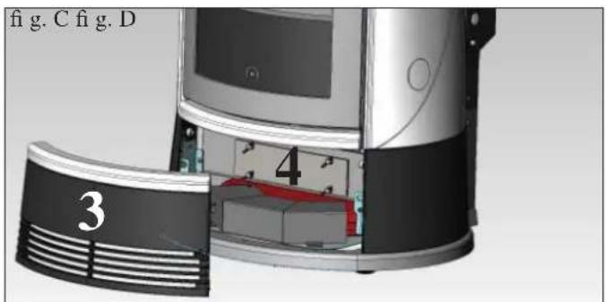
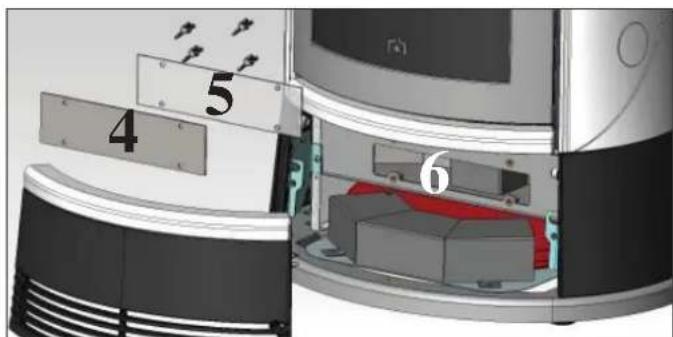
Cleaning the smoke duct
- When the thermo stove is off and cold, agitate the cleaning rod energetically (see previous page).
Remove the lower front cast iron panel (3 - fig. C) and remove the steel inspection panel (4 - fig. C/D), complete with silicone gasket (5 - fig. D), fixed with wing nuts. Clean the silicone gasket and vacuum resid from the flue pipe (6 - fig. D).
The thermo stove comes with a spare silicone gasket.
The amount of residue will depend on the type of fuel and system.
Failure to carry out this cleaning procedure may cause the boiler-stove to block.
ONCE THE PROCEDURE IS IMPLEMENTED,ENSURE THAT THE INSPECTION HATCH IS CLOSED PROPERLY.
POSSIBLE TROUBLESHOOTING
In the event of problems the boiler-stove stops automatically and runs the shutdown process and the display shows text regarding the motivation of the shutdown (see the various alarms below).
Never pull the plug during shutdown on account of malfunction.
To start the boiler-stove up again after a shutdown, let the shutdown procedure end (10 minutes marked by a beep) and then press the button 0/1.
Do not turn the boiler-stove on again before checking the cause of the malfunction and CLEANING/ EMPTYING the crucible.
INDICATION OF POSSIBLE CAUSES OF MALFUNCTION AND INDICATIONS AND REMEDIES:
1) Signalling: H2O PTC_FAULT
Problem: Shut down due to the water temperature sensor being broken or disconnected.
Actions: - Check connection of the sensor to the control board.
- Verify functionality by means of a cold test
2) Signalling: Verific./extract.: (this trips if the smoke extraction speed sensor detects a fault)
Problem: Shutdown for smoke extraction speed fault detection
Actions: Check smoke extractor function (devolution sensor connection) and board (DEALER).
- Check smoke channel for dirt
- Verify the electrical system and earthing system.
- Check electronic circuit board (DEALER).
3) Signalling: Stop/Flame: (this trips if the thermocouple detects a smoke temperature lower than the value set, which it interprets as the absence of fl ames)
Problem: Turns off due to drop in smoke temperature
Flame may fail for any of the following reasons:
-
lack of pellets
-
too many pellets have suffocated the flame, check pellet quality (DEALER)
- the maximum thermostat has intervened (rare, this only intervenes in the event of excessive smoke temperature) (DEALER)
4) Signalling: Block_FI/NO Start: (intervenes if a flame fails to appear within a maximum of 15 minutes, or if ignition temperature is not reached).
Problem: Turns off due to incorrect smoke temperature during ignition
Distinguish either of the following cases:
Flame does NOT appear
Actions: Check: - combustion chamber position and cleanliness;
-
arrival of combustion air in the combustion chamber;
-
if the heating element is working (DEALER);
- room temperature (if lower than 3^ use a firefighter) and damp.
- Try to light with a firelighter (see page 47).
Flames appear, but AF appears on the display after Ar.
Actions: Check: (only by the Dealer)
- if the thermocouple is working (DEALER);
- start-up temperature setting in the parameters (DEALER).
5) Signalling: Black Out: (not a defect of the boiler-stove).
Problem: Turns off due to lack of electricity
Actions: Check electricity connection and drops in voltage.
6) Signalling: Fault/RC: (intervenes if the thermo coupling has failed or is disconnected).
Problem: Turns off due to thermo coupling failed or disconnected
Actions: Check connection of thermo coupling to board:
- Check function in cold test (DEALER).
POSSIBLE TROUBLESHOOTING
7) Signalling: smoke ^ C / high : (turns off due to exceeding maximum smoke temperature).
Problem: Switching off due to exceeding the maximum smoke temperature.
Check (only by the Dealer):
-
pellet type, anomaly in smoke extraction,
-
smoke channel blocked,
- incorrect installation.
- gear motor 'drift'
8) Signalling: H2O TEMPALARM (Activated if the water sensor is faulty or disconnected)
Problem: Shut down due to water temperature being higher than 90^ .
An excessive temperature may occur because of the following:
- system too small: ask the DEALER to activate the ECO function
- blockage: clean the exchanger pipes, the combustion chamber and the smoke outlet.
9) Signalling: Verific./air flow: (intervenes if the flow sensor detects insufficient combustion).
Problem: Turns off for lack of depression
-
Flow may be insufficient if there is a hatch open or the hatch is not perfectly sealed (e.g. seal flawed).
-
This may also be the case if there is a problem with air intake or smoke extraction, or if the
-
combustion chamber is blocked or the flow sensor dirty (clean with dry air).
- Also check that the flow sensor limits are within the parameters.
- The depression alarm may also be signalled during ignition, if the chimney flue does not comply with
- specifications or the chimney flue and chimney pot are clogged.
10) Signalling: "Battery check"
Problem: The boiler-stove does not stop but the error appears on the display.
Actions: The buffer battery of the control board needs changing (DEALER).
11) Signalling: HIGH CURRENT ALARM: Activated when anomalous, excessive current is being absorbed by the gear motor.
Actions: Check functioning (CAT): gear motor - Electrical connections and electronic board.
12) Signalling: LOW CURRENT ALARM: Activated when anomalous, insufficient current absorption is detected on the gear motor.
Actions: Check functioning (CAT): gear motor - pressure switch - tank thermostat - electrical connections and electronic board
13) Problem: The pellet DOES NOT enter the crucible:
- The pellets are blocked in the hopper: use a vacuum cleaner to empty the pellet hopper.
- The gear motor is broken (an error is displayed on the synoptic panel).
- The feed screw safety thermostat 'disconnects' the electrical supply of the gear motor: check that it has not overheated. Use a tester or a temporary bridge to verify.
- The water overheating safety thermostat ' disconnects' the electrical supply of the gear motor: check that the boiler contains water. To reset push the button on the left side, after having removed the protective hood.
- If the problem is not resolved, contact the CAT.
14) Problem: synoptic panel is off:
Actions: check the power cable connection,
- check fuse (on power cable),
- check connection of fl at cable to synoptic panel
15) Problem: Remote control not working
Actions: closer to the receiver of the boiler-fireplace
- check the battery and if necessary, replace it.
16) Problem: Water is not hot enough:
Actions: clean the hearth exchanger
NOTA
All signals/warnings remain shown until you intervene on the remote control, by pressing the button 0/1.
Do not use the boiler-stove before having eliminated the problem.
It is important to tell the Dealer exactly what the panel signals.
FAQ
The answers are listed below in summary form, for further details see the other pages of this document.
1) What do I need to prepare in order to install the boiler-fireplace?
Flue pipe at least 80mm in diameter or direct connection to the outside.
An air inlet in the room that is at least 80~cm^2
34 G outlet and inlet ftting.
3 / 4 G drains connection for overpressure valve.
3 / 4 G load fitting
A certified electrical connection with a thermal magnetothermic switch 230V + / - 10% 50Hz
(assess the division of primary and secondary circuits).
2) Can the boiler-stove work without water?
NO. Using the boiler-stove without water will damage it.
3) Does the stove generate hot air?
Yes. Most of the heat produced is transferred to the water, while a fan produces hot air to heat the room.
4) Can I connect the inlet and outlet of the boiler-stove directly to a radiator?
NO, just like other boilers, it must be connected to a collector from which the water is then distributed to the radiators.
5) Do boiler-stove also supply hot sanitary water?
It is possible to produce hot sanitary water evaluating the power of the boiler-stove and the water plant.
6) Can I discharge the smoke from the boiler-stoves along the wall?
NO, a discharge which is conform with standards (UNI 10683) must reach the ridge of the roof, and in any case proper functioning requires a vertical stroke of at least 1.5 meters; avoiding that in case of power outage or wind, a slight amount of smoke forms in the installation environment.
7) Do I need an air inlet in the room where it is installed?
Yes, to replenish the air used by the boiler-stove for combustion; or direct connection t the outside.
8) What settings are required on the boiler-stove display?
The desired water temperature. The boiler-stove will then adjust the power accordingly to obtain or maintain this.
For small systems, a mode can be set that ignites and shuts down the boiler-stove accordingly, as the water temperature is reached. (contact DEALER for initial start up)
9) How often do I need to clean the combustion chamber?
Before each ignition, with the thermo stove off and cold. HAVING BRUSHED OUT THE EXCHANGER PIPES and agitated the flue pipe cleaning rod (see page 52).
10) Do I need to vacuum the pellet hopper?
Yes, at least once a month when the boiler-stove is not used for some time.
11) Can I burn other fuel apart from pellets?
NO. The boiler-stove has been designed to burn wood pellets that are 6mm in diameter. Any other material can damage it.
12) Can I ignite the boiler-stove by sending an SMS?
Yes, if the DEALER or an electrician has installed the connection via an optional cable code 621240 to the serial port behind the boiler-stove.
CHECK LIST
To be integrated with a complete reading of the technical specifications
Positioning and installation
Commissioning done by an approved CAT that issued the guarantee
- Room ventilation
Only the boiler-stove outlet passes through the smoke channel/chimney flue
The smoke channel has: a maximum of 3 curves a maximum of 2 horizontal metres
- The exhaust pipes are made of suitable material (recommended: stainless steel)
- When using any flammable materials (e.g. wood), all precautions have been taken to prevent a fire hazard
The heating capacity has been appropriately assessed considering radiator efficiency: how many kW have been estimated to be necessary???
The hydraulic system has been declared to be compliant with the Ministerial Decree 37 ex Law No. 46/90 by a qualified technician.
Use
- Good quality, dry wood pellets are used (diameter 6mm (maximum permissible humidity 8% ).
- The chimney pot and ash compartment are clean and well positioned.
- The cleaning rods are moved every day.
- The exchanger tubes and internal parts of the hearth are clean.
- The smoke extract duct is clean.
- The bleeding process has been applied to the hydraulic system.
- The pressure (shown on the pressure gauge) is at least 1,5 bar.
REMEMBER TO VACUUM THE COMBUSTION CHAMBER BEFORE EACH IGNITION Should ignition fail, DO NOT re-ignite until you have emptied the combustion chamber.
OPTIONAL
TELEPHONE COMBINER FOR REMOTE IGNITION (code 281900)
The boiler-stove can be ignited remotely by asking the DEALER to connect the telephone combiner to the serial port behind the boiler-stove via the optional cable (code 640560).
CLEANING ACCESSORIES


GlassKamin (code 155240) Used for cleaning the ceramic glass
Ash vacuum cleaner without motor (code 275400) Used for cleaning the hearth
INFORMATION FOR USERS
In accordance with Art. 13 of the Legislative Decree No. 151, dated 25 July 2005, "Implementation of Directives: 2002/95/EC, 2002/96/EC and 2003/108/EC, pertaining to the reduction of hazardous substances used in electrical and electronic equipment, as well as disposal of waste". The crossed-out wheeled bin symbol shown on the equipment or on the packaging indicates that the product must be disposed of separately at the end of its useful life. Therefore, at the end of the equipment's useful life, the user must hand in the equipment to suitable collection facilities for electrical and electronic waste, or return it to the retailer when a new, equivalent appliance is purchased in a ratio of one to one.
Madame, Monsieur,
2006/95/CE - Directive Basse Tension
MI: refoulement installation
RI: retour installation
S: evacuation
MI: refoulement installation
RI:retour installation
S: evacuation
SB: chauffc-bain
MI: refoulement installation
RI: retour installation
S: évacuation
TC: thermopôle
V: soupape a bille
Signalisation reserve pellet

Pression differentielle
a completeness on the lecture's completeness.
Colocacion e instalacion
BEKLEDING DEMONTEREN BIJOUX

Reservesignaling pellets
1) Signaling: H2O PTC_FAULT
10) Signaling: "Battery check"
INSTRUÇões PARA O USO
Painel sinóptico

Whenever the number of pellets is less than 10, the pellet is replaced by a new pellet.
INSTRUÇões PARA O USO
Variacao na alimentacao de pellets (APENAS APOS CONSELHO DO CAT).
Pressionar durantedoesometimesa tecla“M”do controlo remoto epercorrerasindicacoesdo displaycomasteclas " + / - " 1,paraencuentraradiiscriao“ADJ-PELLET”.Confirmarestafa funcao coma tecla menue passarara regulacao da alimentaciono depellets,se diminuirov valor configurado diminuiraalimentacao depellets,seaugentarov valor configurado aumentarale alimentaciono depellets.
INSTRUÇões PARA O USO
CONTROLO REMOTO
TOIIOOETHsH AN Ω KEPAIMKHS EIIΦANEIAZ:
To0oTeHoe Tny avw Kepaui Huaivia (79) enavoo oto xutooi npo ts 6oTn
-Av n avw Kepaikn Eupavia dEiv aovt0epr, apapoeote tnv.
H OToaepooinon TnS avw Kepauuknc Eupavuaic npenei va yivetai, oou eivat anapaitto, toooteovtaus paobda n oioia napexetai, avaeoa sto laotixkka kTnv avw Eupavua Tc 6ouaa ano xotoioidno.
- EAnavatoOnoTeTnToe Tny Avo Kepaikn EInpavla
ΦAΣH E
H6oia eivai etoum yia va too0eetnei stn thon ts.
AΦAIPEΣH EΠENΔYΣΗ Σ BIJOUX

Tn oostn anosvapuoloyon twkapukov npoxnpnte 5s
ΦAΣHA
AopapoeTe tyv avw kepauiK eupaveta (1)
H B/C
AΦAIPEΣH ΠPOΣΟΙΝ KEPAMIKΩN:
Aioovapuolooyntv eavw (2) kai katow ypiua(3) eopapoucovtac 1aikn pieon yia va aodoeuevtai o ta aospalizopeva eaatpia
ApaipoeTe Tc KepaikEs PpOoysic (4-5) ByovtaC pObeLs otepwoon.

ΦAΣH D
AΦAIPEΣH KEPAMIKOY AIO TH ΕΕΙA ΠΑEYPA (XEIPOΛABH):
AvoiTe Tny npota.
AonovapuooynoTe to iioo npopia (6) 5eBodovotac tic Biedes otepoeosn.
ApaipoeTo KepaikO (7) anodoeovotao to ao ta lamakia ovkypatnoq.
Kλειστην πόρτα τοῦ θαλάμου κωσης.
AΦAIPEΣH KEPAMIKOY AIO THN API ΣTEPH ΠΑEYPA:
AopnoTe tyn npro klaetn.
AioovapuooynoTe to iio npoip (8) 5e10ovovtac ts bis stepewon.
ApaipoeTo kepaikco (9) anodeovot to ao ta laukia ovykpatnonca.
TOIOEETHSEIENAYSHTRESOR
ΦAΣHA
ΦAΣHA
H qan aon npovouaetn oupa stny kataoan nou piketau nva apiaepon tns oukeuaiaq ka tny toohton oto xopo.
ΦAΣH B
ΦAΣH B
Aopaeote tucuavteevic npoooyeic (69-52) noiv eiva otepeowevc, ony ouvexia ouvapmooyote me tic biides (71)noo napexovtai, tic kepaikek npoooyis (53) me tic uavteevic npoooyic (69-52), ony ouvexie c enavatoontheta te.
ΦA2H C
ΦAΣH C
Too0ehtote stny avw epiavvua ano xurooio (78) ta tria laotixkua 74) otnv epa tous kai stn ouveia too0ehtote ano naw vnv avw kepaumkn Epiaveia (79).
ΦA∑H D
ΦAΣH D
H6ouaivai etouynyua tonotheetno
TOIIOEETHENYENSTRASS/CAMEO
ΦAΣHA
H aon aut npovouiae tn oupa styn kataoan nou bioketau tnv apaipeon ts oskeuaic ka tny tootheon oto xopo.
ΦAΣH B
Apaepote to npo0io tma (69) npokmuov va npopoeetv a yalee tic do bidec noov ooykpatouv ta dvo npo0ia tmua ano yotoiOpno deia (51) kai apiotepa (49).
H C/D
- 2uvapuooynte tncnAkec (140) oTneipva nlaiv "A-B" (47) u Tg npexoeves c bioc T.E.M 6x12 kau tonoetne pnoopiv, xopiic va biodoe, tC wotodatpntkcs bioc 4,2x9,5 otig doo yovics mlookapioaoc eepoc kai iioo (141-142-152-153) sto kopiog oma.
Too0ctnoTe to nepivo a (47),too0eovtaCto npota cto 8pa "C", otn ouveia npioptpeyte to kai otnpicte to otny avo PEApa etoi 0ote va eapuooi otyn avw yovia D141-152. - 2to oetao aot ophi tte tic bi8c, nov eixote tootheetnoi npoospiva, otis yovies μλokapiogatoc εμnpoc kai πω (141-142-152-153).
HM_· ·
KaTn qoan ovvapuooynon npenei va baowtheta ot ni nertec ivai
eouypaumueves me nyn enavw enuavya ano xotoidno.
Se avtioen npinttoon, onlaoh av eivai nio ma oia vva evdo xiaotua, penei va
papeuBn0ei avaeoa st npertivo naiv to kau to aukk kevtpapoiatos
mu eineon poedla (151) ia va avtotaumotie n aoostao n ts neevduong.
TOIIOEETHENYENSTRASS/CAMEO
ΦAΣH E
- 2uvapuooynoe με tic βδεs (71) ka tic poδéλεc (151) nov παρεoxvta.η
μavεviα πoσoyn (53) σην επαν ω πoσoyn (69), ka επανατοπεθησe “G”.
ApaapéoTe Tny kato npocoyn H52 - 2uvapuooynoe uic ts biides (71) kua tis poedelac(151) nov napexovta nvy aevia npooyn (53) otyn kato npooyn (52) kau eavatoonthetaote stny dpaT
-Enavatoontheta ta 8do avo npoogia tmuata,8e5t (51) ka apotepo (49) ka biodote ta ano unpoota ie ts bioe nov eipae.
To0oTeiToe epiOn Tnv EppoOthia yipua (69).
H F
TooTheeToe stny avw eipavvua ano yotoiOnpo (78) ta tria laotixkua (74) otny epa touc kai stn ouvexia too0eTeTne a no navo to avo tu nma ano yotoiOnpo (79).
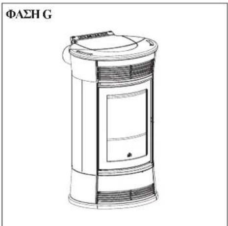
ΦAΣH G
H6oua eivai etouyn yua too0etnon.
O△HΓΕΣ XPHΞHΣ
1° Avapua/△okun με μeipuva tou εovouoodotμevov Kévtpou Tcyukic Ynoptipng ts Edilkamin (CAT)
H
Av n diopooan ovtn dev ivai apketn, eikovovnoe tto KTY, eoioodotnevo kvtpo taoyuknc vnooortnpns Tns Edilkamin, pokoieevov va kaopioeTe tn vaa o0uon naiotopyia.
PELETPAFYLDNING I BEHOLDEREN
After marking af段时间, the program was run on a PC with 10 GB RAM and 2 GB memory. After marking off time, the program was run on a PC with 10 GB RAM and 2 GB memory. After marking off time, the program was run on a PC with 10 GB RAM and 2 GB memory. After marking off time, the program was run on a PC with 10 GB RAM and 2 GB memory. After marking off time, the program was run on a PC with 10 GB RAM and 2 GB memory. After marking off time, the program were able to run on a PC with 10 GB RAM and 2 GB memory. After marking off time, the program was run on a PC with 10 GB RAM and 2 GB memory. After marking off time, the program was run on a PC with 10 GB RAM and 2 GB memory. After marking off time, the program was run on a PC with 10 GB RAM and 2 GB memory. After marking off time, the program was run on aPC with 10 GB RAM and 2 GB memory. After marking off time, the program was run on a PC with 10 GB RAM and 2 GB memory. After marking off time, the program was run on a PC with 10 GB RAM and 2 GB memory. After marking off time, the program was run on a PC with 10 GB RAM and 2 GB memory. After marking off time, the program was run on a PC with 1G RAM and 2GB memory. After marking off time, the program was run on a PC with 10 GB RAM and 2 GB memory. After marking off time, the program was run on a PC with 10 GB RAM and 2 GB memory. After marking off time, the program was run on a PC with 10 GB RAM and 2 GB memory. After marking off time, the program was run on a PC with 10 GB RAM and 2 GB memory. After marked off time, the program was run on a PC with 10 GB RAM and 2 GB memory. After marked off time, the program was run on a PC with 10 GB RAM and 2 GB memory. After marked off time, the program was run on a PC with 10 GB RAM and 2 GB memory. After marked off time, the program was run on a PC with 10 GB RAM and 2 GB memory. After marked off time, she was able to run all programs at once.
Must be proved to be the first to be able to use a computer.
PROVERKA ELEKTRICKEHO PRIPOJE (ZASUVKU UMISTETE NA LEHCE PRISTUPNEM MISTE)
MONTAZ PRAVE BOCNI KERAMIKY (BOK S KLIKCKOU):
Obr.5
PIECYK NIE MOZE FUNKCJONOWAC BEZ WODY W INSTALACJI.
EWENTUALNE ROZPALENIE PIECYKA ,NA SUCHO" SPOWODUJE USZKODZENIE URZADZENIA.
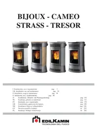
- NOTE
- SAFETY INFORMATION
- IMPORTANT!!!
- DO NOT ATTEMPT TO PUT THE FIRE OUT WITH WATER!
- FEATURES
- Operating modes
- - ELECTRONIC CIRCUIT BOARD
- ELECTRONIC CIRCUIT BOARD
- SERIAL PORT
- BACKUP BATTERY
- - EXTERNAL FINISHES
- BIJOUX
- TRESOR
- STRASS
- CAMEO
- DIMENSIONI
- COMPONENTS - SAFETY AND DETECTION DEVICES
- Smoke thermocouple
- Flow sensor
- Feed Screw safety thermostat
- Water temperature detector
- If the temperature is too high, it starts a shutdown.
- Water overheating safety thermostat
- Overpressure valve 3 bar
- Electric coil
- Smoke extractor
- Vacuum gauge (electronic pressure sensor):
- Tank safety thermostat:
- Pump (circulator)
- Closed expansion tank
- Manometer
- Drain tap
- Venting valve:
- VERIFY COMPATIBILITY WITH OTHER DEVICES
- VERIFYTHE POWER SUPPLY
- CONNECTION (the plug must be accessible)
- FIRE SAFETY DISTANCES AND LOCATION
- AIR INLET (to be mandatorily implemented)
- SMOKE OUTLET
- TYPICAL EXAMPLES
- CHIMNEY POT
- INSTALLATION
- HYDRAULIC CONNECTIONS:
- HEATING SYSTEM WITH THE THERMO STOVE AS THE ONLY HEAT SOURCE
- LEGEND
- HEATING SYSTEM WITH THE THERMO STOVE COMBINED WITH A BOILER
- HEATING SYSTEM WITH THE THERMO STOVE AS THE ONLY SOURCE OF HEAT, WITH SANITARY HOT WATER BEING PRODUCED BY A BOILER
- ACCESSORIES:
- COVERING INSTALLATION BIJOUX
- PHASE A
- PHASE B
- RIGHT SIDE CERAMIC PANEL ASSEMBLY (HANDLE SIDE):
- Fig. 5
- Fig. 6
- Fig. 7
- LEFT SIDE CERAMIC PANEL ASSEMBLY:
- PHASE C
- CERAMIC FRONT PANEL ASSEMBLY:
- PHASED
- CERAMIC TOP ASSEMBLY:
- PHASE E
- BIJOUX COVERING DISASSEMBLY
- PHASE B/C
- DISASSEMBLING THE CERAMIC FRONT PLATES:
- DISASSEMBLY RIGHT SIDE CERAMIC (HANDLE):
- DISASSEMBLY LEFT SIDE CERAMIC:
- COVERING INSTALLATION TRESOR
- COVERING INSTALLATION STRASS/CAMEO
- PHASE C/D
- Note:
- PHASE F
- PHASE G
- INSTRUCTIONS FOR USE
- 1st ignition/test by the Edilkamin authorised Dealer
- The presence of a tank within the boiler-stove does NOT guarantee appropriate protection from thermal expansion occurring in the whole system.
- FILLING THE PELLET HOPPER
- ATTENTION:
- NOTE regarding the fuel.
- Mimic panel
- Filling the feed screw
- Automatic ignition
- Manual ignition (in case of start up failure)
- Shutdown
- Setting the clock
- Programmer to ignite and shutdown the thermal stove at various times during the week.
- Pellet reserve warning
- Variation feeding pellets (ONLY AFTER SUGGESTED BY DEALER)
- Environmental temperature control
- Modulate power mode
- Comfort Clima mode
- Setting the environmental temperature
- Temperature control with external thermostat
- THE ELECTRONIC CIRCULATOR
- Electronic control of operation:
- REMOTE CONTROL
- Key to buttons and display:
- USING THE "EASY TIMER" PROGRAM
- BLOCKED KEYPAD
- LOW BATTERY INDICATOR
- MAINTENANCE
- N.B.
- DAILY MAINTENANCE
- WEEKLY MAINTENANCE
- SEAS ONAL MAINTE NANCE (implemented by the DEALER)
- ATTENTION !!!
- Cleaning the smoke duct
- POSSIBLE TROUBLESHOOTING
- INDICATION OF POSSIBLE CAUSES OF MALFUNCTION AND INDICATIONS AND REMEDIES:
- FAQ
- 1) What do I need to prepare in order to install the boiler-fireplace?
- 2) Can the boiler-stove work without water?
- 3) Does the stove generate hot air?
- 4) Can I connect the inlet and outlet of the boiler-stove directly to a radiator?
- 5) Do boiler-stove also supply hot sanitary water?
- 6) Can I discharge the smoke from the boiler-stoves along the wall?
- 7) Do I need an air inlet in the room where it is installed?
- 8) What settings are required on the boiler-stove display?
- 9) How often do I need to clean the combustion chamber?
- 10) Do I need to vacuum the pellet hopper?
- 11) Can I burn other fuel apart from pellets?
- 12) Can I ignite the boiler-stove by sending an SMS?
- CHECK LIST
- To be integrated with a complete reading of the technical specifications
- Positioning and installation
- Use
- REMEMBER TO VACUUM THE COMBUSTION CHAMBER BEFORE EACH IGNITION Should ignition fail, DO NOT re-ignite until you have emptied the combustion chamber.
- OPTIONAL
- TELEPHONE COMBINER FOR REMOTE IGNITION (code 281900)
- CLEANING ACCESSORIES
- INFORMATION FOR USERS
- Signalisation reserve pellet
- a completeness on the lecture's completeness.
- Colocacion e instalacion
- BEKLEDING DEMONTEREN BIJOUX
- Reservesignaling pellets
- INSTRUÇões PARA O USO
- Painel sinóptico
- Variacao na alimentacao de pellets (APENAS APOS CONSELHO DO CAT).
- CONTROLO REMOTO
- TOIIOOETHsH AN Ω KEPAIMKHS EIIΦANEIAZ:
- ΦAΣH E
- AΦAIPEΣH EΠENΔYΣΗ Σ BIJOUX
- ΦAΣHA
- H B/C
- AΦAIPEΣH ΠPOΣΟΙΝ KEPAMIKΩN:
- ΦAΣH D
- AΦAIPEΣH KEPAMIKOY AIO TH ΕΕΙA ΠΑEYPA (XEIPOΛABH):
- AΦAIPEΣH KEPAMIKOY AIO THN API ΣTEPH ΠΑEYPA:
- TOIOEETHSEIENAYSHTRESOR
- ΦAΣH B
- ΦAΣH C
- TOIIOEETHENYENSTRASS/CAMEO
- H C/D
- HM_· ·
- H F
- ΦAΣH G
- O△HΓΕΣ XPHΞHΣ
- PELETPAFYLDNING I BEHOLDEREN
- PROVERKA ELEKTRICKEHO PRIPOJE (ZASUVKU UMISTETE NA LEHCE PRISTUPNEM MISTE)
- MONTAZ PRAVE BOCNI KERAMIKY (BOK S KLIKCKOU):
- Obr.5
Brand : EDILKAMIN
Model : TRESOR
Category : Cooker