FX-DH116 - Heating Fuxtec - Free user manual and instructions
Find the device manual for free FX-DH116 Fuxtec in PDF.
User questions about FX-DH116 Fuxtec
0 question about this device. Answer the ones you know or ask your own.
Ask a new question about this device
Download the instructions for your Heating in PDF format for free! Find your manual FX-DH116 - Fuxtec and take your electronic device back in hand. On this page are published all the documents necessary for the use of your device. FX-DH116 by Fuxtec.
USER MANUAL FX-DH116 Fuxtec
natural_image
Line drawing of a golf power saw with wheels and wheel rim (no text or symbols)
natural_image
Orange icon of a person reading a book (no text or symbols)
natural_image
Icon of a hand pointing at an open book, rendered in gold outline on black background (no text or symbols)Inhalt
POLSKA WERSJA JEZYKOWA....110
Inhalt
- General information and safety regulations 22
- Device-specific safety instructions 22
- Intended use....24
- Technical data....25
- Assembly & Commissioning....27
- Maintenance....28
- Troubleshooting 31
- Symbols....32
- DECLARATION OF CONFORMITY EU 33
VERSION FRANCAISE....34
POLSKA WERSJA JEZYKOWA....110
natural_image
Line drawing of a portable lawn mower with wheels and a cylindrical top (no text or symbols)text_image
Technical diagram of a mechanical device with labeled parts A through K, showing internal components and directional arrows.text_image
Exploded view diagram of a mechanical assembly with numbered parts for identificationtext_image
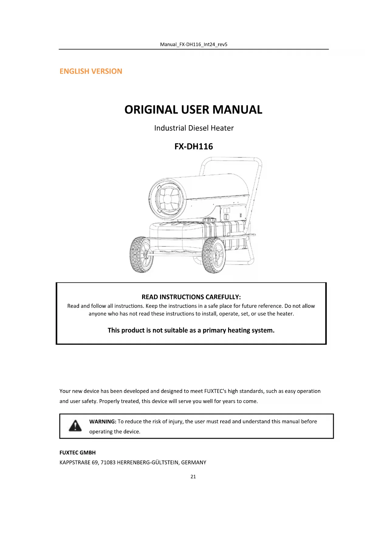
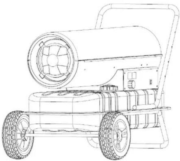
Technical drawing of a mechanical component with dimensional annotations including 5.4, 3.1, and 2.Industrial Diesel Heater
FX-DH116
natural_image
Line drawing of a portable lawn mower with wheels and a cylindrical top (no text or symbols)READ INSTRUCTIONS CAREFULLY:
Read and follow all instructions. Keep the instructions in a safe place for future reference. Do not allow anyone who has not read these instructions to install, operate, set, or use the heater.
This product is not suitable as a primary heating system.
Your new device has been developed and designed to meet FUXTEC's high standards, such as easy operation and user safety. Properly treated, this device will serve you well for years to come.

WARNING: To reduce the risk of injury, the user must read and understand this manual before operating the device.
FUXTEC GMBH
KAPPSTRAße 69, 71083 HERRENBERG-GÜLTSTEIN, GERMANY
We are continually striving to improve our products. Therefore technical data and illustrations can change!
10. General information and safety regulations
Only use the device after you have read and understood the user manual carefully. Familiarize yourself with the operating elements and the correct use of the device. Observe all safety instructions listed in the manual. Behave responsibly towards other people. The operator is responsible for accidents and danger to third parties. If in doubt about the connection or operation of the device, please contact customer service.
In the context of continuous product development, we reserve the right to implement technical changes for improvement. This document is the original user manual.
Read and observe all these instructions before you start up this machine. Keep the safety instructions in a safe place.
Working safely:
Keep your work area in order! Disorder at the workplace can result in accidents.
Take the environmental influences into account. Do not expose the tool to rain. Do not use the device in a damp or wet environment. Ensure good lighting. Do not use the device near flammable liquids or gases.
Keep other people away! Do not let other people, especially children, touch the tool or the cable. Keep them away from the workplace.
Proper storage! Unused devices should be stored in a dry, closed place and out of reach of children.
Do not overload your device. Work within the specified power range.
Use the correct device. Do not use the device for purposes for which it is not intended.
Maintain your device with care. Follow the maintenance instructions and notes. Check the cable of the device regularly and have it replaced by a recognized expert if it is damaged. Do not use the cable to pull the plug out of the socket. Protect the cable from heat and sharp edges. Be careful! Pay attention to what you do! Go to work with common sense. Do not use the device when you are tired.
Have your device repaired by a qualified technician! This device complies with the relevant safety regulations.
Repairs may only be carried out by a qualified technician using original spare parts. Otherwise, accidents may occur for the user.
WARNING!
The use of other accessories can cause a risk of injury to you.
11. Device-specific safety instructions
Read this user manual carefully and completely before attempting to assemble, operate, or maintain this heater. Improper use of this heater may cause severe injury or death by combustion, fire, explosion, electric shock, or carbon monoxide poisoning.
DANGER:
Carbon monoxide poisoning can be fatal!
Carbon Monoxide Poisoning: The early signs of carbon monoxide poisoning are similar to those of the flu, such as headache, dizziness, and nausea. If you notice these symptoms, it could be a sign that your heater is not working correctly. Go outside immediately! Have your heater checked. Some people are more susceptible to carbon monoxide than others: e.g., pregnant women, people with heart or lung disease or anemia, people
under the influence of alcohol, and those at high altitudes. Make sure that you have read and understood all warnings. Keep these instructions for future reference. It is your guide to the safe and proper operation of this heater.
Use only diesel to avoid the risk of fire and explosion. Never use gasoline, naphtha, paint solvents, alcohol, or other highly flammable fuels.
Fuel:
Personnel involved in fuel refilling must be trained and thoroughly familiar with the manufacturer's instructions and applicable guidelines for safe heater refilling. Only diesel fuel may be used. Any flame, including the pilot light, must be extinguished to allow the heater to cool before refilling with fuel.
All fuel lines and connections must be checked for leaks while fuel is being filled. Any leaks must be repaired before the heater is put back into operation.
Do not store more than the daily amount of fuel inside buildings near the heater. All fuel storage facilities must have a minimum distance of 7m from heaters, burners, welding equipment, and similar ignition sources (except the fuel tank integrated into the heater). If possible, fuel storage should be limited to areas where the floor construction prevents the accumulation of fuel spillage, and lower fire sources cannot ignite fuel. Fuel storage must be following local government regulations.
General:
Never operate the heater near gasoline, paint solvents, or other highly flammable vapors.
Follow all local rules and regulations for the use of this heater.
Heaters that are operated near cover mats, tent canvas, or other roofing materials must be placed at a safe distance from these materials. The recommended minimum distance is 3.5m. It is also recommended that fireproof roofing materials are used. The roofing materials must be securely fastened to protect them from the ignition and to prevent them from touching or tipping over the heater in gusts of wind.
Use only in well-ventilated rooms. Before the operation, make sure that per 100,000 BTU/hour heat output, there is a ventilation opening of at least 2800cm ^2 to the fresh outside air.
Use only in places where no flammable vapors or high dust content is present.
Only operate under the voltage and frequency specified on the type plate.
Always use a properly grounded extension cable with a three-pin plug.
To avoid fire hazard, the hot or operating heater must be placed on a safe, level surface.
The heater must be moved or stored in a horizontal position to prevent fuel spillage. Keep the customer and pets away from the heater.
Disconnect the plug from the socket when the heater is not in operation.
Never use the heater in living rooms or bedrooms.
Never block the air inlet (rear) or the air outlet (front) of the heater.
Never move, operate, fill with fuel, or service the hot, operating, or mains connected heater.
CAUTION:
Use only diesel to avoid the risk of fire or explosion.
The use as a heating source for events and festivities, as well as the operation in stables, is strictly prohibited.
Conduct in an emergency:
Initiate first aid measures appropriate to the injury and request qualified medical assistance as soon as possible. Protect the injured person from further damage and keep him or her sedated.
In case of an accident, a first-aid kit, according to DIN 13164, should always be available at the workplace. Any
material removed from the first-aid kit must be refilled immediately.
If you request assistance, please provide the following information:
- Place of the accident
- Type of accident
- Number of injured
- Nature of the injuries
Disposal:
The disposal instructions result from the pictograms on the device or packaging. A description of the individual meanings can be found in the chapter "Symbols."
Disposal of transport packaging:
The packaging protects the device from damage in transit. As a rule, the packaging materials are selected according to environmentally friendly and disposal aspects and can therefore be recycled. Returning the packaging to the material cycle saves raw materials and reduces the amount of waste. Packaging components (e.g., foils, polystyrene) can be dangerous for children. There is a danger of suffocation! Keep the packaging parts out of reach of children and dispose of them as soon as possible.
Qualification:
Apart from detailed instruction by a competent person, no special qualification is required for the use of the device.
Minimum age:
The product is intended for use by persons over 16 years of age.
If the product is to be used by children over 8 years of age or by persons with reduced physical, sensory or mental abilities or lack of experience and knowledge, you must be supervised or instructed regarding the safe use of the device and understand the resulting dangers. Children must not play with the device. Children must not perform cleaning and user maintenance without supervision.
Training:
The use of the device only requires appropriate instruction by a competent person or the user manual. Special training is not necessary.
12. Intended use
The DH series oil burners are to be used exclusively for indirect heating and drying in well-ventilated rooms or dry outdoor areas, at a safe distance from burning materials as well as people and living beings. Make sure that the surface is stable and horizontal during operation. Only diesel is permitted as fuel.
Safety devices:
The oil heating burner is equipped with an electronic flame monitoring system. If one or more malfunctions occur, this will cause the device to stop. If the oil burner overheats, an overheating thermostat will intervene and stop the fuel supply; the thermostat will reset itself when the temperature of the combustion chamber has fallen to the maximum permitted value. Before restarting the oil burner, the cause of overheating must be
found and eliminated (e.g., clogging of the air intake or outlet or stoppage of the fan). To restart the device, follow the instructions in the "Startup" section.
13. Technical data
Model: FX-DH116
Engine power fan: 30kW
Fan power: 750m^3/h
Chimney connection diameter: 120mm
Fuel supply: Diesel
Consumption: 2.4kg/h
Electrical supply: 220V-240V/50Hz
Air pressure adjustment range: 0,31
Electrical input power: 230W
Weight without fuel: 19,2 kg
Tank capacity: 38L
Product size: 855*470*588mm
| Model identifier: FX-DH116 | |||||||
| The functionality of indirect heating: [no] | |||||||
| Direct heat emission: 30(kW) | |||||||
| Indirect heat emission: N/A (kW) | |||||||
| Fuel | Emissions of ambient heat (*) | ||||||
| NOx | |||||||
| Select fuel type | [Liquid] | Kerosene | 69 [mg/ kWhinput] (GCV) | ||||
| Element | Symbol | Value | Unit | Element | Symbol | Value | Unit |
| Heat output | Efficiency (NCV) | ||||||
| Nominal heat output | Pnom | 30 | kW | Efficiency at the nominal heat output | _th,nom | 100 | % |
| Minimum heat output (indicative) | Pmin | N/A | kW | Efficiency at minimum heat output (indicative) | _th,min | N/A | % |
| Auxiliary power consumption | Type of heat output/room temperature control (selection) | ||||||
| At nominal heat output | elmax | 0,002 | kW | Single-stage heat output, no room temperature control | [no] | ||
Manual_FX-DH116_Int24_rev5
| At minimum heating power | el_min | N/A | kW | Two or more manual steps, no room temperature control | [no] | ||
| In standby mode | elsb | N/A | kW | With mechanical thermostat room temperature control | [no] | ||
| With electronic room temperature control | [yes] | ||||||
| with electronic room temperature control plus daily time switch | [no] | ||||||
| with electronic room temperature control plus weekly time switch | [no] | ||||||
| Further control options (multiple selections possible) | |||||||
| Room temperature control, with presence detection | [no] | ||||||
| Room temperature control, with open window detection | [no] | ||||||
| With distance control option | [no] | ||||||
| With adaptive start control | [no] | ||||||
| With the working time limit | [no] | ||||||
| With black ball sensor | [no] | ||||||
| Permanent pilot flame power required | |||||||
| Pilot flame performance requirements (if applicable) | P_pilot | 0 | kW | ||||
| Contact details | FUXTEC GmbH, Kappstr. 69, 71038 Herrenberg | ||||||
| (*) NOx = nitrogen oxides | |||||||
| The seasonal space heating energy efficiency ηS | |||||||
| Element | Symbol | Value | Unit | ||||
| Seasonal room heating energy efficiency in active operation | ηS, on | 100 | % | ||||
| a correction factor (F1) | / | 0 | % | ||||
| a correction factor (F2) | / | 7 | % | ||||
| a correction factor (F3) | / | 0 | % | ||||
| a correction factor (F4) | / | 0 | % | ||||
Manual_FX-DH116_Int24_rev5
| a correction factor (F5) | / | 0 | % |
| Biomass label factor | BLF | 1 | / |
| The seasonal space heat energy efficiency ηS | ηs | 97 | % |
| Energy efficiency classes | A | ||
14. Assembly & Commissioning
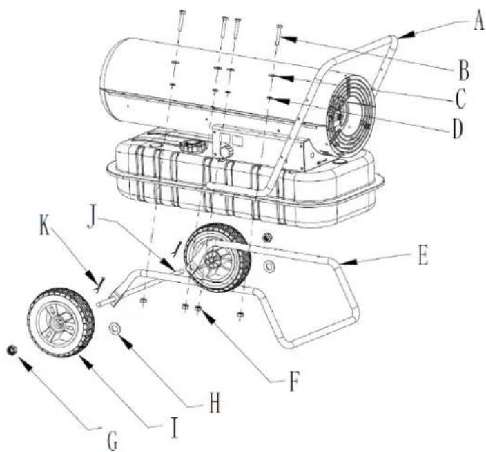
text_image
Technical diagram of a mechanical device with labeled components and directional arrows indicating motion or assembly.Mount the device, as shown in the picture.
Start it:
Fill the tank with clean fuel. Use only diesel fuel. You can read the level in the fuel gauge above the tank.
Connect the power cord. Grounding is mandatory. Now the ambient temperature is displayed. Slide the power switch to "ON." If the temperature control is set so that the temperature is higher than the ambient
temperature, the heater will start after 7 seconds.
If the temperature controller is set lower, the device will not start.
Cold start:
At low temperatures, keep the air vent closed with one finger to start.
If the heater locks up, you will have to do a manual restart:
Check and remove the cause of the lockout before restarting the heater. To reset, set the On/OFF switch to 0
and then back to I. If the lockout is repeated, contact customer service.
Switch off:
Slide the switch to OFF and disconnect the device from the power supply.
Do not disconnect from the power supply during operation. Keep the device connected during the cooling sequence. Do not cover the heater. Do not block the air inlet and outlet. The heater cover is very hot after operation. Do not touch it! Wear protective clothing. Do not touch the device with wet hands.
15. Maintenance
Keep the air slots and the housing dust and dirt free and the housing dust and dirt free. Use a soft cloth and a mild soap solution for cleaning. Avoid direct contact with harsh cleaning agents with the device. Do not use aggressive, volatile, or corrosive cleaning agents. The device must be protected from moisture and dust. When not in use for a more extended period, keep the device covered and in a dry, safe place out of reach of children.
ATTENTION!
Do not carry out any maintenance work as long as the heater is connected to the socket, in operation, or hot. Failure to do so may result in severe burns and electric shock.
Inspection and maintenance plan:
Wipe the housing regularly with a soft sponge or cloth. For very dirty parts, use a sponge with lukewarm water and a mild detergent. Check the power cord regularly: if it is worn or damaged, it must be repaired by a specialist. Store the device in a dry and cool place.
Nozzle:
Carefully unscrew the nozzle, clean the nozzle head from dirt, and replace the nozzle if damaged.
Air Filter:
Clean the air filter. Remove the cover at the end of the filter (11), clean the air inlet filter (10) with detergent and dry it thoroughly before reinstalling. Replace the air inlet filter (9) once a year.
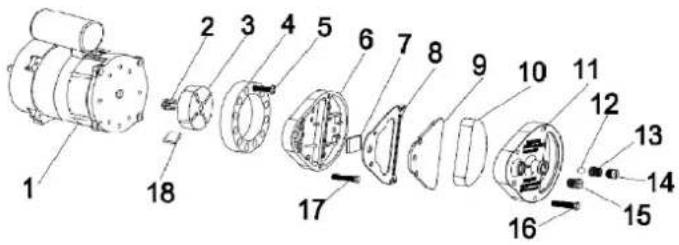
text_image
Exploded view diagram of a mechanical assembly with numbered parts for identificationDo not carry out any electrical repairs yourself. Contact a specialist. Do not use a defective device. When cleaning, make sure that no water gets into the housing. Do not open the housing to access the internal parts.
Do not spray water into the heater.
Do not use solvents, gasoline, toluene, or similar aggressive chemicals to clean the heater.
Ignition electrodes:
Clean, adjust, and, if necessary, replace the ignition electrode. For electrode gaps, dimensions in MM.
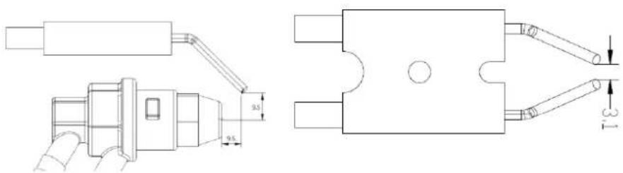
text_image
Technical drawing of a mechanical component with dimensional annotations including 3.5 and 3.1 measurements.Compressor pressure setting:
The compressor is delivered ex-works and may only be checked and adjusted by qualified personnel.
Interventions in the device can be dangerous.
Remove the cap. If necessary, adjust the pressure to the correct value, turn the screw clockwise for pressure increase, counterclockwise for the decrease. Air pressure should be (bar) 0.31.
Electrically:
Check cables, electrical parts, and connections regularly.
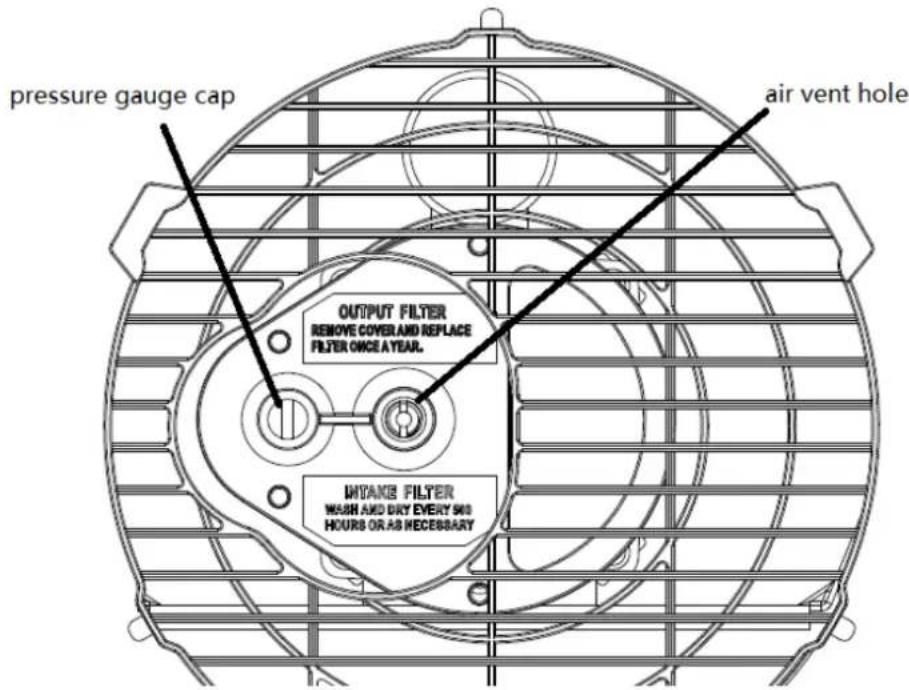
text_image
pressure gauge cap air vent hole OUTPUT FILTER REMOVE COVER AND REPLACE FILTER ONCE A YEAR. INTAKE FILTER WASH AND DRY EVERY 500 HOURS OR AS NECESSARYCircuit diagram:
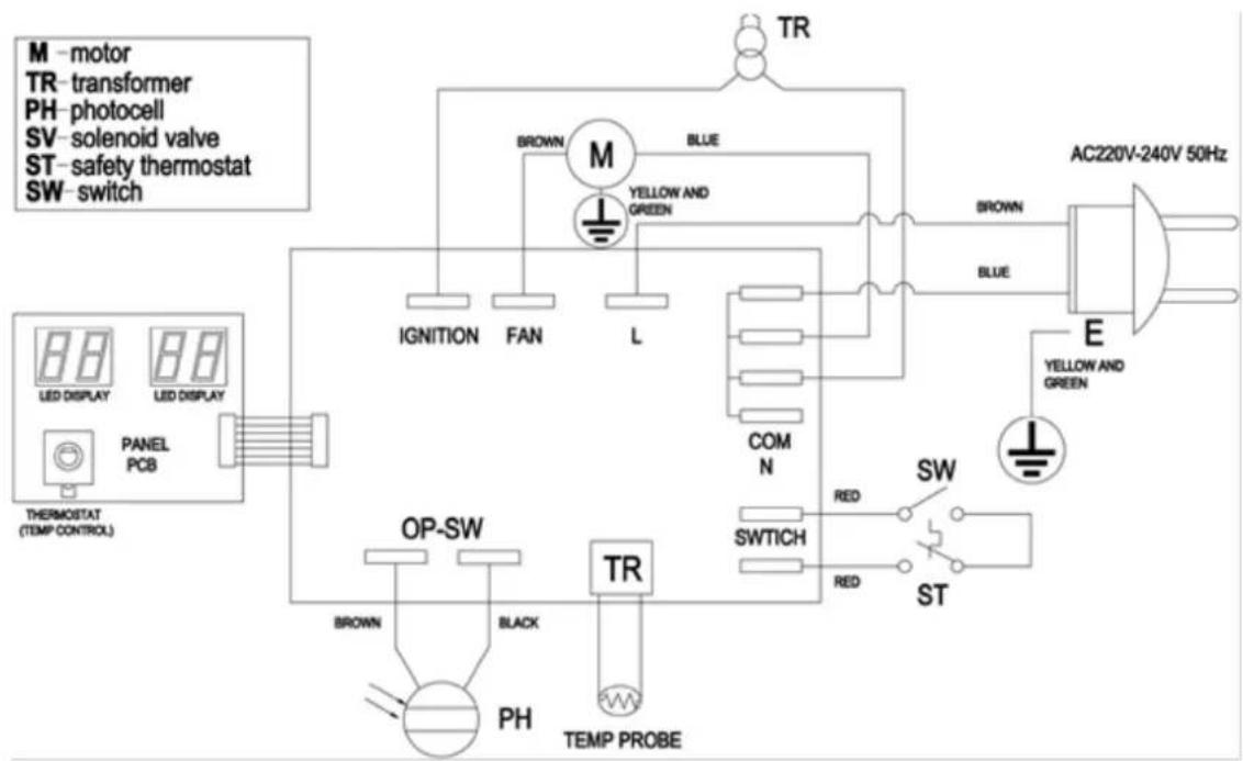
flowchart
graph TD
    A["AC220V-240V 50Hz"] --> B["TR"]
    B --> C["M"]
    C --> D["BROWN"]
    C --> E["BLUE"]
    C --> F["L"]
    C --> G["MINI"]
    C --> H["COM N"]
    C --> I["SWITCH"]
    C --> J["ST"]
    K["THEMORSTAT (TEMP CONTROL)"] --> L["LED DISPLAY"]
    K --> M["PANEL PCB"]
    K --> N["OP-SW"]
    K --> O["PH"]
    K --> P["TR"]
    P --> Q["BROWN"]
    P --> R["BL"]
    P --> S["BL"]
    P --> T["SWITCH"]
    P --> U["ST"]
    V["BRIDGE"] --> W["TR"]
    X["BRIDGE"] --> Y["TR"]
    Z["BRIDGE"] --> AA["TR"]
    AB["BRIDGE"] --> AC["TR"]
    AD["BRIDGE"] --> AE["TR"]
    AF["BRIDGE"] --> AG["TR"]
    AH["BRIDGE"] --> AI["TR"]
    AJ["BRIDGE"] --> AK["TR"]
    AL["BRIDGE"] --> AM["TR"]
    AN["BRIDGE"] --> AO["TR"]
    AP["BRIDGE"] --> AQ["TR"]
    AR["BRIDGE"] --> AS["TR"]
    AT["BRIDGE"] --> AU["TR"]
    AV["BRIDGE"] --> AW["TR"]
    AX["BRIDGE"] --> AY["TR"]
    AZ["BRIDGE"] --> BA["TR"]
- Troubleshooting
| Fault | Cause | Measure |
| The engine does not startE1 Error on the display | - No current or low voltage- Power cable defective or damaged- Engine/Capacitor defect- Device locked due to overheating | - Check the power line and voltage, check the fuse- Check the power cord and replace it- Check the engine and capacitor and replace it if necessary.- Determine the cause of overheating- Wait a few minutes and restart the device |
| The engine runs, but the heater does not ignite and locks after a short time | - Empty fuel tank, dirty or wrong fuel- Fuel filter clogged- Hole in the oil line- Burner nozzle clogged- Fuel Viscosity not good | - Remove wrong or dirty fuels- Fill the tank with clean diesel- Clean or replace the fuel filter- Check Hoses- Clean nozzle, blow in compressed air |
| Flames come out of flame tube outletE1 or E4 Error on display | - Insufficient airflow in the combustion chamber- Compressor pressure too high- The thermostat adjusted to room temperature and reached | - Check air intake, fan, motor.- Check air pressure- The regular operation, To turn the temperature control knob clockwise |
| The heating stops during operationE1 or E4 Error on display | - Flame failure- Poor combustion- Airflow reduced- Overheating | - Check and remove the cause of the fault- Turn the power switch to 0 and then to 1- Call the customer service |
17. Symbols

18. DECLARATION OF CONFORMITY EU
Herewith we,
FUXTEC GMBH
KAPPSTRAße 69, 71083 HERRENBERG, GERMANY
declare that the machine described below, due to its design and construction and in the version marketed by us, complies with the relevant essential health and safety requirements of the EC directives.
Designation of the machine:
Industrial Diesel Heater
Machine type:
FX-DH116
Trademark:
FUXTEC
Applied harmonized EN 13842:2004
standards:
EN 60335-1:2012+A1
EN 60335-2-102:2006+A1
EN 62233:2008
EN 55014-1:2006+A1+A2
EN 55014-2:2015
EN 61000-3-2:2013
EN 61000-3-3:2014
Manufacturer signature/date:
C. Jille
Leonhard Zirkler, 13.09.2022
The name and address of the person
FUXTEC GMBH - KAPPSTRAße 69, 71083 HERRENBERG, GERMANY
authorized to compile the technical
documentation established within the
Community
VERSION FRANCAISE
MODE D'EMPLOI ORIGINAL
natural_image
Line drawing of a manual lawn mower with two wheels and a cylindrical top (no text or symbols)LISEZ ATTENTIVEMENT LES INSTRUCTIONS :
text_image
Technical diagram of a mechanical device with labeled parts A through K, showing exploded and assembled views.text_image
Exploded view diagram of an electric motor with numbered parts for identificationFig.3
text_image
Technical diagram showing a mechanical assembly with labeled dimensions 9.5 and 9.5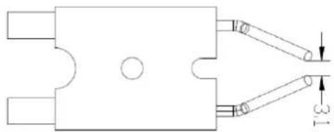
natural_image
Pure mechanical component diagram without any text, numbers, or symbolsFig. 5
text_image
pressure gauge cap output filter REMOVE COVER AND REPLACE FILTER ONCE A YEAR. INVAKE FILTER WASH AND DRY EVERY 500 HOURS OR AS NECESSARY air vent holenatural_image
Line drawing of a portable lawn mower with wheels and a cylindrical top (no text or symbols)LEGGERE ATTENTAMENTE LE ISTRUZIONI:
text_image
Technical diagram of a cylindrical structure with labeled components A, B, and C, showing internal flow or movement arrows.text_image
Exploded view diagram of an electric motor with numbered parts for identificationall'anno.
text_image
Technical drawing of a mechanical component with dimensional annotations including 3.5 and 3.1 unitstext_image
pressure gauge cap air vent hole OUTPUT FILTER REMOVE COVER AND REPLACE FILTER ONCE A YEAR.natural_image
Line drawing of a portable lawn mower with wheels and a cylindrical top (no text or symbols)LER ATENTAMENTE AS INSTRUÇÕES:
text_image
Technical diagram of a mechanical device with labeled parts A through K, showing internal components and directional arrows.Montar o aparelho como indicado na figura.
Inicio:
text_image
Exploded view diagram of a mechanical assembly with numbered parts for identificationtext_image
Technical drawing of a mechanical component with dimensional annotations including 0.5 and 3.1 units.natural_image
Line drawing of a portable lawn mower with wheels and a cylindrical top (no text or symbols)LEES DE INSTRUCTIES ZORGVULDIG DOOR:
Gedrag in noodsituaties:
text_image
Technical diagram of a mechanical device with labeled parts A through K, showing internal components and directional arrows.text_image
Exploded view diagram of a mechanical assembly with numbered parts for identificationtext_image
Technical drawing of mechanical components with dimension annotations including 5.4, 9.5, and 3.1Compressordrukinstelling: