FX-GH51 - Heating Fuxtec - Free user manual and instructions
Find the device manual for free FX-GH51 Fuxtec in PDF.
| Brand | Fuxtec |
| Model | FX-GH51 |
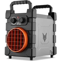
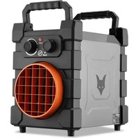
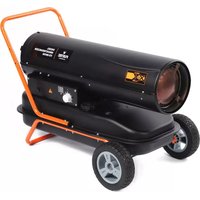
| Product type | Gas heater |
| Recommended use | Outdoors or well-ventilated industrial areas |
| Gas supply | Liquid gas (LPG) |
| Gas supply pressure | 1500 mBar |
| Gas consumption | 2.18 - 3.63 kg/h |
| Thermal power | 10,200 - 17,000 BTU (30 - 50 kW) |
| Power supply | 220-240 V ~ 50 Hz |
| Ignition | Manual piezoelectric |
| Flame control | Gas valve with thermal sensor |
| Overheat protection | 110°C |
| Blown air temperature | 360°C |
| Built-in fan | Yes, with fan-only function |
| Grounding required | Yes |
| Minimum safety distance | 3 m from flammable materials |
| Maintenance | Annual check by a professional, cleaning with compressed air |
| Spare parts | Gas hose, regulator, electrode, original parts recommended |
| Recycling | Triman marking, separation of packaging |
| Standards | EN1596:1998 + A1:2004, EU directive 2016/426 |
Frequently Asked Questions - FX-GH51 Fuxtec
User questions about FX-GH51 Fuxtec
0 question about this device. Answer the ones you know or ask your own.
Ask a new question about this device
Download the instructions for your Heating in PDF format for free! Find your manual FX-GH51 - Fuxtec and take your electronic device back in hand. On this page are published all the documents necessary for the use of your device. FX-GH51 by Fuxtec.
USER MANUAL FX-GH51 Fuxtec
natural_image
Line drawing of a black FUXTEC air purifier with attached device (no text or symbols)
natural_image
Orange icon of a person reading a book on black background (no text or symbols)
Inhalt
DEUTSCHE VERSION....6
ENGLISH VERSION....19
VERSION FRANCAISE 27
POLSKA WERSJA JEZYKOWA 100
Sommaire
Inhalt....1
Sommaire....3
DEUTSCHE VERSION....6
POLSKA WERSJA JEZYKOWA 100
natural_image
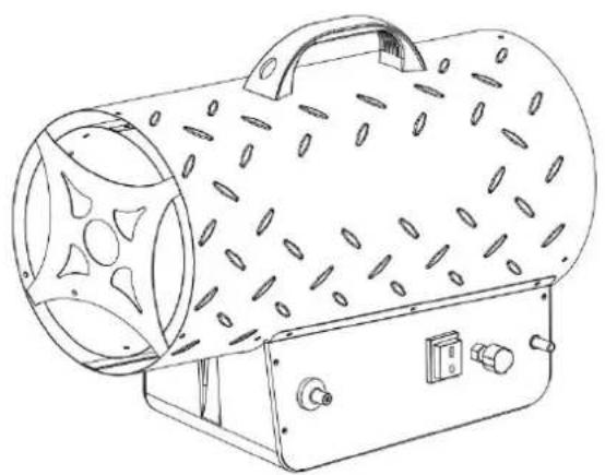
Line drawing of a cylindrical industrial device with perforated panel and control buttons (no text or symbols)- SCHALTPLAN
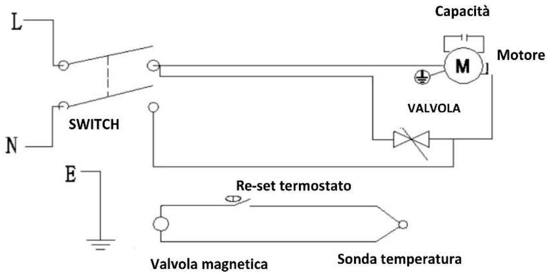
text_image
L N E SWITCH Capacitance M Motor VALVE Re-set thermostat Deflated magnetic valve Temperature probe- SPEZIFIKATIONEN DES HEIZGERÄTES
natural_image
Line drawing of a gas cylinder connected to a portable air vent (no text or symbols)(Abbildung 1)
natural_image
Simple line drawing of a wall-mounted electrical outlet with a warning symbol (no text or labels)Abbildung 2
natural_image
Simple line drawing of a door switch, lock, and handle (no text or symbols)
natural_image
Technical line drawing of a mechanical component with no visible text or symbolsnatural_image
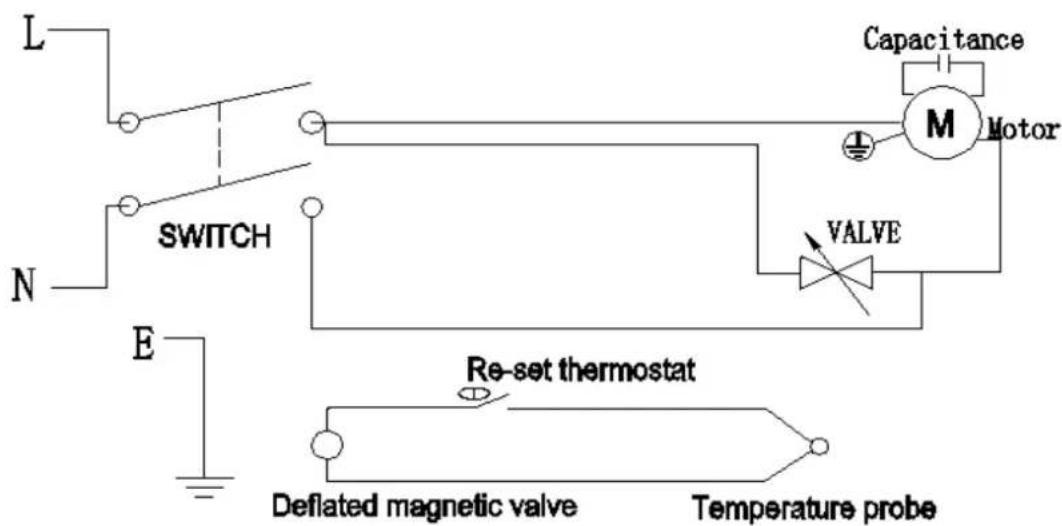
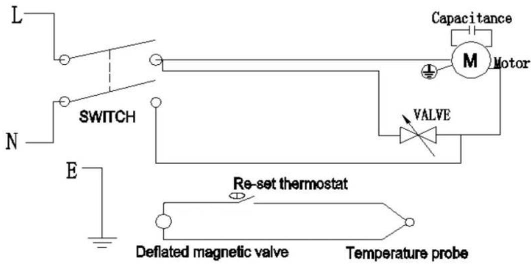
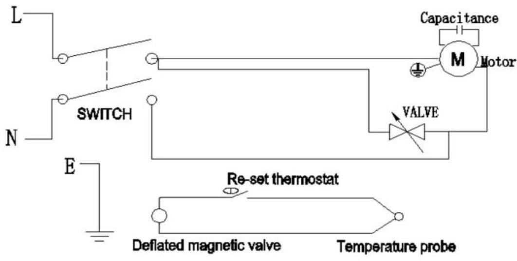
Line drawing of a cylindrical industrial device with perforated panel and control buttons (no text or symbols)12. CIRCUIT DIAGRAM

text_image
L N E SWITCH Capacitance M Motor VALVE Re-set thermostat Deflated magnetic valve Temperature probe13. HEATER SPECIFICATIONS
| Model | BGA1401-30T | BGA1401-50T |
| Rating | 61,500BTU-10,2000BTU(18-30kw) | 10.2000BTU-17,0000BTU(30-50kw) |
| Fuel Consumption | 1.30-2.18kg/h | 2.18-3.63kg/h |
| Fuel Orifice Port Size | 1.28mm | 1.4mm |
| Air Flow Temp. | 430°C | 360°C |
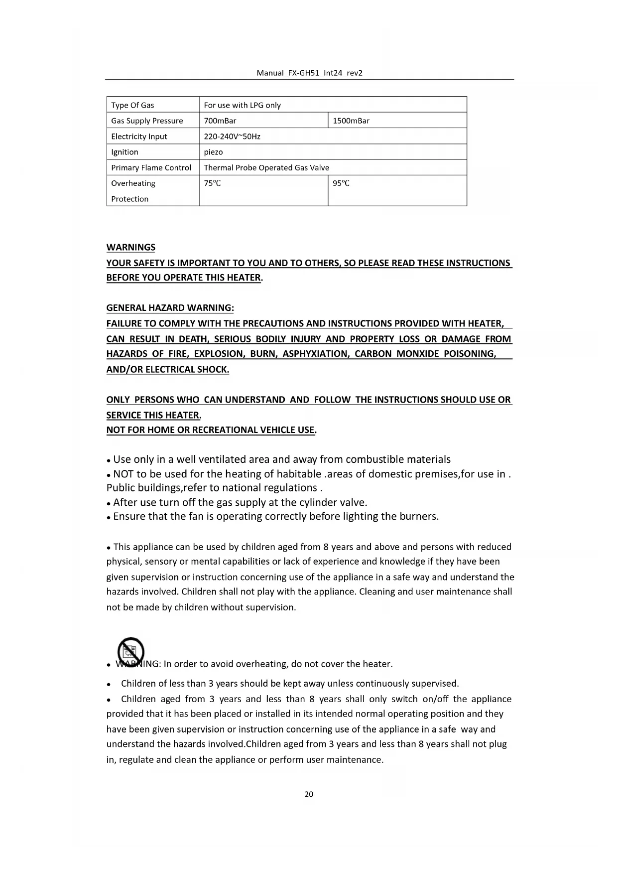
| Type Of Gas | For use with LPG only | |
| Gas Supply Pressure | 700mBar | 1500mBar |
| Electricity Input | 220-240V~50Hz | |
| Ignition | piezo | |
| Primary Flame Control | Thermal Probe Operated Gas Valve | |
| Overheating Protection | 75°C | 95°C |
WARNINGS
YOUR SAFETY IS IMPORTANT TO YOU AND TO OTHERS, SO PLEASE READ THESE INSTRUCTIONS BEFORE YOU OPERATE THIS HEATER.
GENERAL HAZARD WARNING:
FAILURE TO COMPLY WITH THE PRECAUTIONS AND INSTRUCTIONS PROVIDED WITH HEATER, CAN RESULT IN DEATH, SERIOUS BODILY INJURY AND PROPERTY LOSS OR DAMAGE FROM HAZARDS OF FIRE, EXPLOSION, BURN, ASPHYXIATION, CARBON MONXIDE POISONING, AND/OR ELECTRICAL SHOCK.
ONLY PERSONS WHO CAN UNDERSTAND AND FOLLOW THE INSTRUCTIONS SHOULD USE OR SERVICE THIS HEATER.
NOT FOR HOME OR RECREATIONAL VEHICLE USE.
- Use only in a well ventilated area and away from combustible materials
- NOT to be used for the heating of habitable .areas of domestic premises,for use in . Public buildings,refer to national regulations .
• After use turn off the gas supply at the cylinder valve. - Ensure that the fan is operating correctly before lighting the burners.
- This appliance can be used by children aged from 8 years and above and persons with reduced physical, sensory or mental capabilities or lack of experience and knowledge if they have been given supervision or instruction concerning use of the appliance in a safe way and understand the hazards involved. Children shall not play with the appliance. Cleaning and user maintenance shall not be made by children without supervision.

- WARNING: In order to avoid overheating, do not cover the heater.
• Children of less than 3 years should be kept away unless continuously supervised. - Children aged from 3 years and less than 8 years shall only switch on/off the appliance provided that it has been placed or installed in its intended normal operating position and they have been given supervision or instruction concerning use of the appliance in a safe way and understand the hazards involved. Children aged from 3 years and less than 8 years shall not plug in, regulate and clean the appliance or perform user maintenance.
- CAUTION-some parts of this product can become very hot and cause burns. Particular attention has to be given where children and vulnerable people are present.
Safety Clearance
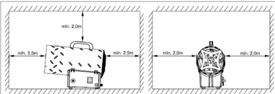
- The heaters mentioned in this manual must only be used outdoors or in well ventilated surroundings.
- For every KW it is necessary to have permanent ventilation of 25cm^3 , equally distributed between the floor and high level, with a minimum outlet of 250cm^3 .
• Gas cylinders must be used and kept in accordance with current regulations. - Never direct the hot air flow towards the cylinder.
- Use only the supplied pressure regulator.
- Never use the heater without its cover.
- Do not exceed 100W/m^3 of free room. The minimum volume of the room must be larger than 100m^3 .
- Do not obstruct the inlet or outlet sections of the heater.
- If the heater has to work for a long period at its maximum capacity, it's possible that ice will form on the cylinder. This is due to excessive vapour withdrawal. Not for this reason, or for any other, should the cylinder be heated. To avoid this effect, or at least to reduce it, use a large cylinder or two cylinders linked together (figure1).
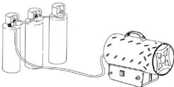
natural_image
Line drawing of a gas cylinder connected to a cylindrical device with attached tubing (no text or symbols)(figure1)
- Do not use the heater in cellars, basements or in any room below the ground level.
• In case of malfunction, please contact the technical assistance service.
• After use, turn the gas cylinder tap off.
- The gas bottle must always be replaced following safety rules away from any possible source of ignition.
• The gas hose must not be twisted or bent.
- The heater must be placed where there is no risk of fire, the hot air outlet must be at least 3m from any flammable wall or ceiling and must never be directed towards the gas bottle.
- Only use original gas hose and spare parts.
• Heaters described in this leaflet are not intended for domestic use.
- In the case that a gas leak is found or suspected, immediately close the gas cylinder, switch the heater off and do not use it again until it has been checked by a qualified service centre. If the heater is installed indoors, provide a good ventilation by opening door and windows completely. Do not produce sparks or free flames.
• If in any doubt contact your supplier.
15. INSTALLATION
- Connect the heater to a suitable electric socket /230V\~50Hz
• Make sure that the machine is properly earthed.
- Connect the gas supply hose to the pressure regulator and connect the regulator to a suitable LPG cylinder.
- Open the tap of the cylinder and check the supply hose and fittings for gas leak. For this operation it is recommended to use an approved leak detector.
- For automatic appliances, connect the room thermostat to the socket on the appliance and adjust it to the required temperature.
16. INSTRUCTION FOR USE
PREPARING FOR OPERATION
- Check the heater for possible shipping damage.
- Connect the hose and regulator assembly to the LPG cylinder by rotating the nut counterclockwise into the LPG cylinder's valve outlet and securely tighten.
- Open the cylinder's gas valve and check all gas connections with a soap and water solution.
- Connect power cord to well-grounded 220-240V\~, 50Hz source of power.
IGNITION / Manual ignition
- Turn the power switch to position I and check that the fan starts running correctly. (Figure. 2)
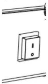
natural_image
Simple line drawing of a wall-mounted electrical switch with an exclamation mark (no text or symbols)Figure.2
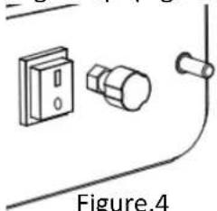
- Push the gas valve button and push repeatedly the piezoelectric lighter until the flame lights up. (Figure 3-4)
natural_image
Simple line drawing of a door switch and knob with a separate lock, labeled Figure.4 (no text or symbols on the diagram itself)Figure.3

natural_image
Technical line drawing of a mechanical component with a central hub and mounting holes (no text or symbols)Figure.4
- As the flame lights up, keep the valve button pushed for 10 seconds approx. should the heater stop when the valve button has been released, wait one minute and repeat the starting operation keeping the valve button pushed for a longer time.
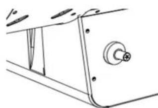
- Regulate the gas flow pressure according to the thermal power desired, by turning the wheel of the pressure reducer anticlockwise to increase the pressure or clockwise to decrease.
- Contact your supplier should any problem continue.
- Regulate the flame and output by turning the adjustable knob anticlockwise to increase or clockwise to decrease. (Figure 3).
CAUTION
If ignition is difficult or irregular before repeating the ignition operations make sure that the fan is not locked and the air inlet and outlet are unobstructed.
SWITCH OFF
To stop the heater, shut off the gas cylinder tap. Let the fan run until the flame shuts down and then turn the fan switch to position O.
AIR CONDITIONING
• The heater can also be used as a ventilator.
- In this case remove the gas supply hose and connect the plug of heater to a suitable electrical supply.
- Set the fan switch to position I.
ODOR FADE WARNING
! ! ! WARNING
Asphyxiation Hazard
- Do not use heater for heating human quarters.
- Do not use in unventilated areas.
- The flow of combustion and ventilation air must not be obstructed.
- Proper ventilation air must be provided to support the combustion air requirements of the heater being used.
- Lack of proper ventilation air will lead to improper combustion.
- Improper combustion can lead to carbon monoxide poisoning leading to serious injury or death. Symptom of carbon monoxide poisoning can include headaches dizziness and difficulty in breathing.
FUEL GAS ODOR
LP gas and natural gas have manmade odorants added specifically for detection of fuel gas leaks.
If a gas leak occurs you should be able to smell the fuel gas. Since Propane (LP) is heavier than air you should smell for the gas odor low to the floor. ANY GAS OROR IS YOUR SIGNAL TO GO INTO IMMEDIATE ACTION!
- Do not take any action that could ignite the fuel gas. Do not operate any electrical switches. Do not pull any power supply or extension cords. Do not light matches or any other source of flame. Do not use your telephone.
- Get everyone out of the building and away from the area immediately.
- Close all propane (LP) gas tank or cylinder fuel supply valves, or the main fuel supply valve located at the meter if you use natural gas.
- Propane (LP) gas is heavier than air and may settle in low areas. When you have reason to suspect a propane leak, keep out of all low areas.
- Use your neighbor's phone and call your fuel gas supplier and your fire department. Do not reenter the building or area.
- Stay out of the building and away from the area from the area until declare safe by the firefighters and your fuel gas supplier.
- FINALLY, let the fuel gas service person and the firefighters check for escaped gas. Have them air out the building and area before you return. Properly trained service people must repair any leaks, check for further leakages, and then relight the appliance for you.
17. MAINTENANCE
- The repairs or maintenance operations must only be carried out by qualified personnel.
-
The unit must be checked by a qualified technician at least once a year.
-
Regularly check the conditions of gas hose, and gas regulator if it must be replaced only use original spare parts.
- Before starting any maintenance operation on the heater disconnect from both gas and electrical suppliers.
- If the unit has not been used for a long period we advise that a technician carries out a general check up before using. It is important to control the following:
- Periodically check the gas supply hose conditions and, should it be changed, use only original spare parts.
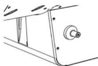
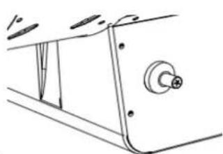
- Check the starting electrode position (see Fig.5).
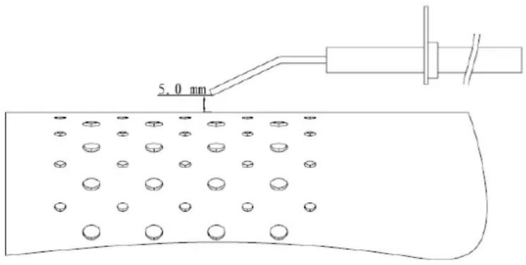
text_image
5.0 mm- Check the connections of the safety thermostat and of the thermocouple: they must always be clean.
If necessary clean the fan blade and the inside of the heater using compressed air.
- TROUBLESHOOTING
| PROBEM | CAUSES | SOLUTIONS |
| The motor does not work | No electricity supply | Check the terminal board with a tester |
| The safety thermostat is on | Wait about one minute then restart | |
| The motor works, but the burner does not light up and after few seconds the heater stops | The cylinder gas tap is closed | Open the gas tap |
| The cylinder is empty | Use a new cylinder | |
| The nozzle is obstructed | Remove the nozzle and clean it. | |
| The solenoid gas valve is not open | Check that the solenoid valve works | |
| There is no spark | Check the position of electrode | |
| The burner lights up but after few seconds the heater stops | No connection with the earthing system | Check and connect properly |
| Defective connection between sensor and safety device | Check and connect properly | |
| Defective safety device | Replace the safety device | |
| The heater stops during operation | Excessive gas supply | Check the pressure reducer and if required replace it |
| Insufficient air flow | Check that the motor works properly | |
| Insufficient gas supply due to ice formation on the cylinder | Check and use a larger cylinder or two cylinders connected together. |
19. EU Declaration of Conformity
We, FUXTEC GmbH, Kappstraße 69, 71083 Herrenberg - Germany, herewith declare the product described below complies with the safety and health requirements of the relevant European standards due to its design and construction and in the version placed on the market by us.
In the event of a change to the products not agreed with us, this declaration loses its validity.
Designation of the product: Gas heating canon
Product type: Gas heater
Brand: FUXTEC
Serien-No.: FX-GH51....
The article complies with the EC Directives: (EU) 2016/426
Applied harmonised standards:
EN1596:1998 + A1:2004
Herrenberg, 11.07.2023
C. Jille
Leonhard Zirkler CEO
LISEZ ATTENTIVEMENT LES INSTRUCTIONS :
natural_image
Line drawing of a cylindrical industrial device with perforated lid and control panel (no text or symbols)text_image
L N E SWITCH Capacitance M Motor VALVE Re-set thermostat Deflated magnetic valve Temperature probenatural_image
Line drawing of a gas cylinder connected to a portable air vent (no text or symbols)(Figure 1)
natural_image
Simple line drawing of a wall-mounted electrical outlet with a warning symbol (no text or labels)Figure 2
natural_image
Simple line drawing of a door switch, lock, and bulb components (no text or symbols)Figure 3
natural_image
Technical line drawing of a mechanical component with mounting holes and a central hub (no text or symbols)natural_image
Line drawing of a cylindrical industrial device with perforated panel and control buttons (no text or symbols)- SCHEMA ELETTRICO
natural_image
Line drawing of a portable gas cylinder connected to a cylindrical device with attached tubing (no text or symbols)(Figura1)
natural_image
Simple line drawing of a wall-mounted electrical switch with an exclamation mark (no text or symbols)Figura 2
natural_image
Simple line drawing of a door handle and keyhole (no text or symbols)Figura 3
natural_image
Technical line drawing of a mechanical component with a knob and mounting bracket (no text or symbols)Figura 4
natural_image
Line drawing of a cylindrical industrial device with perforated panel and control buttons (no text or symbols)42. DIAGRAMA DE CABLEADO
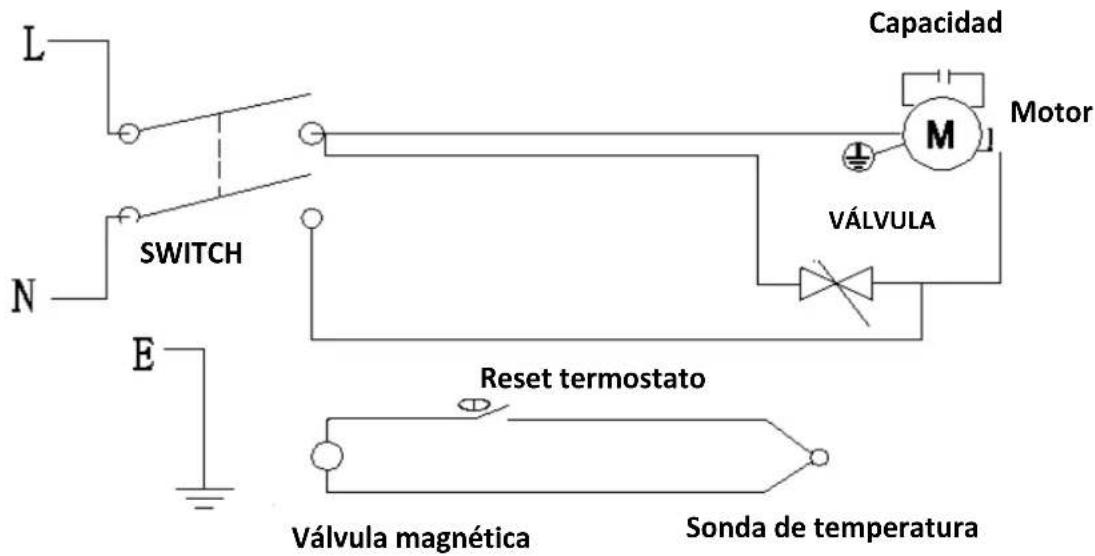
text_image
Capacidad Motor M VÁLVULA SWITCH N E Reset termostato Válvula magnética Sonda de temperaturanatural_image
Line drawing of a gas cylinder connected to a portable air vent (no text or symbols)(Figura1)
natural_image
Simple line drawing of a wall-mounted electrical outlet with warning symbol (no text or labels)Figura 2
natural_image
Simple line drawing of a door switch, bulb, and clip components (no text or symbols)
natural_image
Technical line drawing of a mechanical component with a central knob and flange (no text or symbols)Figura 3
natural_image
Line drawing of a cylindrical industrial device with perforated panel and control panel (no text or symbols)- PLANO DE CABLAGEM

text_image
L N E SWITCH Capacitance M Motor VALVE Re-set thermostat Deflated magnetic valve Temperature probe- ESPECIFICAÇÕES DO AQUECEDOR
natural_image
Line drawing of a gas cylinder connected to a portable air vent (no text or symbols)(Figura 1)
natural_image
Simple line drawing of a wall-mounted electrical switch with an exclamation mark (no text or symbols)Figura 2
natural_image
Simple line drawing of a door handle and lock components (no text or symbols)Figura 3 Figura 4
natural_image
Technical line drawing of a mechanical component with mounting holes and a central knob (no text or symbols)natural_image
Line drawing of a cylindrical industrial device with perforated panels and control buttons (no text or symbols)- BEDRADINGSSCHEMA
text_image
L N E SWITCH Capacitance M Motor VALVE Re-set thermostat Deflated magnetic valve Temperature probe- SPECIFICATIES VAN DE VERWARMING
natural_image
Line drawing of a portable air conditioner unit connected to three cylindrical gas cylinders (no text or symbols)(Afbeelding 1)
natural_image
Simple line drawing of a wall-mounted electrical switch with an exclamation mark (no text or symbols)Figuur 2
natural_image
Simple line drawing of a door handle and keyhole (no text or symbols)natural_image
Technical line drawing of a mechanical component with a central knob and flanges (no text or symbols)!!!! WAARSCHUWING !!!!!
Verstikkingsgevaar
natural_image
Line drawing of a cylindrical industrial device with perforated panels and control buttons (no text or symbols)- SCHEMA FÖR KABELDRAGNING

text_image
L N E SWITCH Capacitance M Motor VALVE Re-set thermostat Deflated magnetic valve Temperature probe- SPECIFIKATIONER FÖR VÄRMAREN
natural_image
Line drawing of a portable air conditioner unit connected to three cylindrical gas cylinders (no text or symbols)(Bild 1)
natural_image
Simple line drawing of a wall-mounted electrical outlet with a warning symbol, no text or labels presentnatural_image
Simple line drawing of a door handle and keyhole (no text or symbols)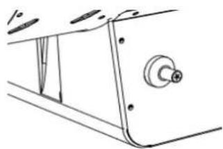
natural_image
Technical line drawing of a mechanical component with no visible text or symbolsBild 3 Bild 4
WARNING FÖR LUKTAVFÄRGNING
!!!! WARNING !!!!!
Risk för kvävning
POLSKA WERSJA JEZYKOWA
81. SCHEMAT STRUKTURY
natural_image
Line drawing of a cylindrical industrial machine with perforated panel and control buttons (no text or symbols)- HARMONOGRAM OKABLOWANIA
text_image
L N E SWITCH Capacitance M Motor VALVE Re-set thermostat Deflated magnetic valve Temperature probe- SPECYFIKACJA GRZEJNIKA
natural_image
Line drawing of a gas cylinder connected to a portable air vent (no text or symbols)(Rysunek 1)
natural_image
Simple line drawing of a wall-mounted electrical outlet with a warning symbol, no text or labels presentnatural_image
Simple line drawing of a door switch, lock, and handle (no text or symbols)Rysunek 3 Rysunek 4