FX-PS152 - Lawn mower Fuxtec - Free user manual and instructions
Find the device manual for free FX-PS152 Fuxtec in PDF.
| Product Type | Professional gas-powered brush cutter |
| Brand | Fuxtec |
| Model | FX-PS152 |
| Engine | 2-stroke, air-cooled |
| Displacement | 52 cm³ |
| Maximum power | 2.2 kW (at 7,500 rpm) |
| Maximum engine speed | 9,000 rpm |
| Idle speed | 3,000 rpm |
| Cutting diameter | 440 mm (nylon line Ø 2.5 mm) |
| Cutting tool types | Nylon line, 3-tooth metal blade |
| Fuel tank capacity | 1.2 L |
| Fuel consumption | 0.98 kg/h |
| Dry weight | 8.5 kg |
| Sound pressure level | 99.5 dB(A) (K=3 dB) |
| Guaranteed sound power level | 113 dB(A) |
| Handle vibration | 5.259 m/s² (k=1.5 m/s²) |
| Power source | Unleaded gasoline mixed with 2-stroke oil (40:1) |
| Main functions | Cutting grass, weeds, bushes |
| Regular maintenance | Air filter cleaning, spark plug, blade sharpening, fuel drain for storage |
| Warranty | 24 months |
| Country of manufacture | Germany (FUXTEC GmbH headquarters) |
Frequently Asked Questions - FX-PS152 Fuxtec
User questions about FX-PS152 Fuxtec
0 question about this device. Answer the ones you know or ask your own.
Ask a new question about this device
Download the instructions for your Lawn mower in PDF format for free! Find your manual FX-PS152 - Fuxtec and take your electronic device back in hand. On this page are published all the documents necessary for the use of your device. FX-PS152 by Fuxtec.
USER MANUAL FX-PS152 Fuxtec
natural_image
Line drawing of a manual tool with a mounted sensor or measuring device against a black background (no text or symbols)
natural_image
Orange icon of a person reading a book (no text or symbols)
natural_image
Icon of a hand pointing at an open book with horizontal lines representing text (no actual text or symbols)DEUTSCHE VERSION....11
ENGLISH VERSION....37
VERSION FRANCAISE....62
POLSKA WERSJA JEZYKOWA ......217
Inhalt
DEUTSCHE VERSION....11
-
Technical Data 38
-
Symbols and safety instructions on the machine....39
-
Intended use and general safety instructions 42
-
Notes on accessories .... 44
-
Notes on working with the metal blade....45
-
Putting on the shoulder harness 46
-
Component overview ....47
-
Mounting the device....48
-
Cold start of the engine 52
-
Warm start of the engine ....53
-
Stopping the device ....53
-
Trimming techniques....53
-
Replacing Nylon Thread....55
-
Maintenance plan....56
-
Storage of the device....58
-
Troubleshooting....59
-
Customer Service....60
-
Warranty....60
-
Disposal note 60
-
EU Declaration of Conformity....61
VERSION FRANCAISE....62
POLSKA WERSJA JEZYKOWA 217
natural_image
Exterior view of a manual grass meter with black body, orange handle, and metal rod (no text or symbols visible)CE
natural_image
Technical line drawing of a mechanical assembly with no visible text or symbolsnatural_image
Mechanical assembly diagram showing a lever mechanism with a black base and arrow indicating motion (no text or symbols)
natural_image
Close-up of a hand holding a metallic mechanical component with arrows indicating direction (no text or symbols visible)
natural_image
Hand holding a metallic tool with a handle, against a plain white background (no text or symbols visible)Installation des Schutzschildes
natural_image
Close-up of a black and orange robotic brush tool with a circular base, mounted on a metal rod (no text or symbols visible)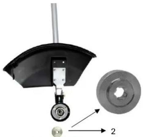
natural_image
Mechanical component diagram showing a wheel assembly with a gear and a circular component, no text or symbols present.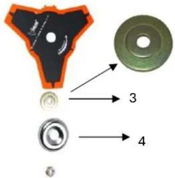
text_image
Diagram of mechanical components with numbered parts labeled 3 and 4, showing cross-sectional views of a component.
natural_image
Two-step diagram showing a tool being inserted into a mechanical component, with no visible text or symbols.Montage des Rasentrimmers (Fadenspule)
Schritt 1:
text_image
2 1 Warning! !Warnung!
text_image
Tankdeckel max_Füllstandnatural_image
Close-up of a black and orange handheld device with a red arrow indicating motion or change (no text or symbols visible)
natural_image
Close-up of a mechanical component with orange and black parts, showing a red arrow pointing to a green cable or wire (no text or symbols visible)natural_image
Close-up of a black and orange electric shock absorber with a hand adjusting its top panel, showing a red arrow indicating the tool (no text or symbols visible)
natural_image
Close-up of a hand adjusting a black industrial machine component with orange clamps (no visible text or symbols)natural_image
Illustration of a naval gun firing from a ship deck, with no visible text or symbols
natural_image
Technical line drawing of a mechanical assembly with an arrow indicating a component (no text or symbols present)natural_image
Diagram of a mechanical device emitting particles or smoke, with arrows indicating direction (no text or symbols)TRIMMEN UM BÄUME
natural_image
Close-up of a black plastic component with an orange plastic cover and red directional arrows indicating motion or flow (no text or symbols)14. Wartungsplan
natural_image
Close-up of a hand adjusting a black FIXTEC device with orange handle (no visible text or symbols)
natural_image
Close-up of a mechanical device with black housing and orange handle (no visible text or symbols)
natural_image
Close-up of a black plastic electronic device casing with a circular vent and a rectangular cover (no visible text or symbols)Wartung Zündkerze
text_image
0.6~0.7mmWARNUNG

natural_image
Black and orange manual lawn brush tool with attached lever and head (no visible text or symbols)CE
Your new device has been developed and designed to meet FUXTEC's high standards, such as easy operation and user safety. Properly treated, this device will serve you well for years to come.

WARNING: To reduce the risk of injury, the user must read and understand this manual before operating the device.
FUXTEC GMBH
CAPPING ROAD 69, 71083 HERRENBERG, GERMANY
We are continually striving to improve our products. Therefore technical data and illustrations may change!
- Technical Data
| Type | FX-PS152 | FX-PS162 |
| Engine | air-cooled; 2-stroke | air-cooled; 2-stroke |
| Cubic capacity | 51.7cm^3 | 62cm^3 |
| Maximum output power (kW)(conformity with ISO 8893) | 2.2kW / 7,500min^-1 | 2.6kW / 7,500min^-1 |
| The maximum speed of the engine | 9,000 min^-1 | 9,000 min^-1 |
| Idle speed of the device | 3,000 min^-1 | 3,000 min^-1 |
| The maximum speed of the spindle (motor scythe) | 7,100 min^-1 | 7,100 min^-1 |
| The maximum speed of the spindle (lawn trimmer) | 6,600 min^-1 | 6,600 min^-1 |
| L_PA at the operator's position | 99.5dB(A) (K=3dB) | 101.0 dB(A) (K=3dB) |
| Measured L_WA according to ISO 10884 | 107.7dB(A) (K=3dB) | 106.9 dB(A) (K=3dB) |
| Guaranteed L_WA | 113dB(A) | 113dB(A) |
| Maximum vibration values at each handle | 5.259m/s^2 k=1.5m/s^2 | 8.124m/s^2 k=1.5m/s^2 |
| Maximum thread diameter | 440mm ( 2.5mm) | 440mm ( 2.5mm) |
| Diameter of the metal blade | 305mmx1.6mm-2T / 255mmx1.6mm-3T/255mmx1.6mm-4T/ 255mmx1.6mm-8T | 305mmx1.6mm-2T /255mmx1.6mm-3T/255mmx1.6mm-4T/255mmx1.6mm-8T |
| Rotation direction of the cutting device | Counterclockwise (see the mark on the plate) | Counterclockwise (see the mark on the plate) |
| Number of the handle | 2 pieces | 2 pieces |
| Dry weight (without fuel, cutting assembly,carrying strap) | 8.5kg | 8.67kg |
| Fuel tank capacity (L) | 1.2 | 1.2 |
| Fuel consumption (kg/h) (in accordance with ISO 8893) | 0.98 | 0.98 |
| Specific fuel consumption (g/kWh) (in accordance with ISO 8893) | 630 | 630 |
22. Symbols and safety instructions on the machine


WARNING! INADEQUATE CONDITIONS MAY LEAD TO SERIOUS INJURY

READ AND UNDERSTAND THIS USER MANUAL BEFORE USE.

ALWAYS WEAR EYE PROTECTION, EAR PROTECTION, AND HEAD PROTECTION

WEAR FOOT PROTECTION.

WEAR GLOVES (sharp edges!).

text_image
15m(50ft)ALWAYS KEEP 15 METERS AWAY FROM OTHER PEOPLE

THE GUARANTEED NOISE LEVEL COMPLIES WITH THE LEGAL NOISE GUIDELINES
 | NO SMOKING AND OPEN FLAMES NEAR THE DEVICE |
 | WARNING:DANGER OF HOT COMPONENTS |
 | ALWAYS SWITCH OFF THE DEVICE AND ENSURE THAT THE CUTTING TOOL IS STOPPED BEFORE CLEANING, REMOVING OR ADJUSTING IT. |
 | WARNING:EXHAUST GASES OF THIS PRODUCT CONTAIN CHEMICALS THAT CAUSE CANCER, BIRTH DEFECTS AND OTHERS |
 | WARNING! NEVER CHANGE THE MACHINE. IMPROPER USE OF THE DEVICE CAN CAUSE SERIOUS OR FATAL PERSONAL INJURY. |
 | WARNING! COMBUSTIBLE MATERIALS |
 | MAXIMUM SPEED OF THE SPINDLE (LAWN TRIMMER): 6600 min ^-1 |
 | MAXIMUM SPEED OF THE SPINDLE (MOTOR SCYTHE): 7100 min ^-1 |
Do not allow others to use this device unless they have been fully instructed, have read and understood the user manual, and have been trained in the operation of the device.

Prolonged use of the device exposes the user to shocks that can lead to white finger disease (Raynaud's syndrome) or carpal tunnel syndrome. This condition reduces the hand's ability to feel and regulate temperature, causes numbness and heat sensations,
and can lead to nerve and circulatory damage and tissue death.
Not all factors leading to white finger disease are known. Still, cold weather, smoking, and other conditions affecting the blood vessels and blood circulation, as well as extensive or prolonged exposure to shocks, are mentioned as factors in the development of white finger disease. Observe the following to reduce the risk of white finger disease and carpal tunnel syndrome
- Wear gloves and keep your hands warm.
• Take regular breaks.
All the precautions mentioned above cannot exclude the risk of white finger disease or carpal tunnel syndrome. Long-term and regular users are, therefore, recommended to closely monitor the condition of their hands and fingers. Consult a doctor immediately if any of the above symptoms occur.

The operating noise of the tool can damage your hearing. Wear sound-proofing (Oropax or earmuffs) to protect it. Long-term and regular users are advised to check their hearing regularly. Be especially vigilant and careful when wearing hearing protection, as it limits your ability to hear warnings (cries, alarms, etc.).

WARNING: A certain amount of noise pollution from this device cannot be avoided. Do not carry out noisy work during permitted and designated times. If necessary, observe rest periods and limit the duration of work to the bare essentials. Appropriate hearing protection must be worn for their personal protection and the protection of persons in the vicinity.
23. Intended use and general safety instructions
This device may only be used for mowing or trimming grass, weeds, and undergrowth. Never apply it for other purposes, as this may result in serious injury!
Correct safety instructions must be followed. DO NOT EXPOSE YOURSELF OR OTHERS TO DANGER. Follow these general safety instructions:
- Always wear safety glasses for eye protection. Long hair must be tied back. Do not wear loose clothing or jewelry that may get caught in moving parts of the device. Safe, secure, non-slip safety shoes must always be worn. It is recommended that legs and feet are fully protected to protect against flying objects during operation.
-
Check the entire device for loose parts (nuts, bolts, screws, etc.) Service or replace them if necessary before using the device. Do not use accessories with this drive head other than those recommended by the manufacturer. Otherwise, severe injury to the user or bystanders and damage to the device may result.
-
Keep the handles free of oil and fuel.
• Always use correct handles and the shoulder strap when cutting - Do not smoke when mixing the fuel or filling the tank
- Do not mix fuel in an enclosed space or near open fires. Make sure there is sufficient ventilation/aeration
- Mix and store the fuel mixture in a sealed container approved for such use according to local regulations.
- Never remove the fuel filler cap while the device is running
- Do not operate the device in closed rooms or buildings. Exhaust gases contain dangerous carbon monoxide.
- Do not try to adjust the device while walking or carrying it. Always set the device on a flat, free surface.
- Do not use the device if it is damaged. Never remove protective devices from it. Failure to do so may result in serious injury to the operator or bystanders and damage to the device.
- Check the area to be cut and remove any residue that may be entangled in the nylon cutting head or cutting blade. Also, remove all possible objects that the device could throw around while cutting.
- Never leave the device unattended.
- Don't stretch yourself too far forward. Always maintain a firm stand and balance. Do not run the device while standing on a ladder or any other unstable standing position.
- Children must not have access to the device. Spectators should stand at a safe distance of at least 15 meters from the working area.
- Keep hands and feet away from the nylon cutting head or metal blade during operation.
- Do not use the device if you are tired, ill, or under the influence of medicines, drugs, or alcohol.
- Use an undamaged nylon cutting head. If you hit a stone or any other obstacle, stop the device and check the nylon cutting head. A defective or unbalanced nylon cutting head must never be used.
- Before starting, after failure or impact, always check the device and make sure that it is in good condition.
- Attention! Local regulations may limit the use of the device
- Always keep the device with the cutting tool in good condition. Observe, improper maintenance, the use of non-compliant spare parts or removal, or modification of the safety devices can cause damage to the device and severe injury to the person working with it.
- Secure the device properly during transport to prevent loss of fuel, damage to the device, and injury. Always fit the transport protection of the cutting blade before transporting or stowing the device.
- For devices with a clutch, regularly check that the cutting attachment stops rotating when the engine is idling.
- Check the device for loose fasteners, fuel leaks, damaged parts, etc. before each use. Replace damaged parts before use.
- It is necessary to take sufficient breaks and change the working position.
- Do not store the device in an enclosed area where fuel vapors can reach an open fire from water heaters, stoves, etc. Store the device in a well-ventilated area only
- IMPORTANT: When filling the fuel, make sure that the device is off and cooled down. Never refuel when the device is running or hot. If gasoline is spilled, wipe it up before starting the device
24. Notes on accessories
- Make sure that your product is only equipped with original accessories. Only use original parts that are specified by the manufacturer. The use of any other attachments or accessories may cause injury to the user and damage to the device.
- Clean the device thoroughly, especially the fuel tank and air filter. After using the device, remove all fuel.
- If you approach a user of the device as a spectator, carefully attract his attention and confirm that the user will stop the device. Please do not startle or distract the user. Otherwise, you could cause an unsafe situation.
- Never touch the nylon cutting head or metal blade when the device is running. If it is necessary to replace the guard or cutting tool, be sure that the device and cutting tools have stopped.
- The device must be OFF before you change the working range of it.
- If necessary, have the device repaired by an authorized dealer. If the device is defective, do not continue to run it.
- When starting or operating the device, never touch hot parts such as the exhaust, ignition cables, or spark plug.
- After the device has stopped, the exhaust pipe is still hot. Never place the device near inflammable materials (dry grass, flammable gases or liquids, etc.).
- Pay particular attention to the fact that the ground may be slippery when operating the device in the rain or immediately after the rain.
- If you slide or fall to the ground, release the throttle immediately
- Before removing the blockage, stop the device and remove the spark plug connector. Before adjusting or repairing the device, make sure that the device is stopped, and the spark plug connector is removed.
- Ensure that you do not drop the device or hit it against obstacles.
- If the device is to be stored for an extended period, drain fuel from the fuel tank and carburetor, clean the parts, place the device in a safe place and ensure that the device has cooled down completely.
- Perform constant checks to ensure the safe and efficient operation of the device. For a complete inspection, please contact a specialist workshop.
- Keep the device away from fire or sparks.
- Be careful when using it. There is a risk of kick-back and recoil.
- Exercise extreme caution when using this device with the cutting blade. A cutting blade kick-back is a reaction that can occur when the rotating cutting blade hits an object that cannot be cut. This contact causes the cutting blade to stop for a moment and then suddenly repels from the hit object with accelerated force. This kick-back reaction can be severe enough that the operator loses control of the device. A cutter blade kick-back can occur without warning if the cutter blade encounters an obstacle that becomes blocked or jams. This is more likely in areas where it is difficult to see the material being cut. For easy and safe cutting,
approach the weeds to be cut from your right to your left side. If an object or stick of wood is hit unexpectedly, this can reduce a cutter blade kick-back.
25. Notes on working with the metal blade
A metal blade with 3 teeth is delivered with the device. It is used for cutting bushes and weeds. The use of the saw blade with this device is prohibited.
WARNING

Do not cut with blunt, cracked or damaged metal sheets.
Before working, check the surface for obstacles such as stones, metal bars or other objects. If they cannot be removed,
mark this position to avoid collision with
the blade. Lines can become entangled on the blade head and flap or be swirled in the air.
WARNING

Do not use the motor scythe for cutting out trees.
WARNING

Always use the shoulder strap. Adjust and fix the belt and
Clamp the belt on the device so that the device hangs a few cm above
the ground. The cut-out head and the protective shield should be aligned horizontally in all directions. Pre-tension the machines on the right side of your body.
WARNING

Also, wear head, eye, face and hearing protection, and safety shoes. Do not wear rings and jewelry or
loose, dangling clothes that could get caught in the device.
Do not wear footwear with unprotected toes and do not work
barefoot or without leg protection. In certain situations,
you must wear head protection.
26. Putting on the shoulder harness

shoulder strap is equipped with a quick-release device (see picture). You can quickly remove the shoulder strap by pulling on the quick-release device.
Read the manual carefully. Be thoroughly familiar with the control and correct use of the device.
Understand how to stop and shut down the device. Understand how to quickly release a clamped attachment.
Do not allow anyone to enter the DANGER ZONE while working. The DANGER ZONE is an area of 15 meters in radius (approximately 16 steps). Insist that people in the DANGER ZONE wear eye protection against flinging objects. If the device must be used where people are unprotected, work at a low, reduced speed to reduce the risk of skidding.
27. Component overview

text_image
1 2 3 4 5 6 7 8 9 10 11 12 13 14 15 16 17 18 19 20 FUXTEC- Nylon thread head
- Cutting blades
- Shield
- Drive axle
- U-Handle
- Carrying Strap Mount
- Anti-vibration unit
- Air filter cover
- Choke lever
-
Tank
-
Pull-rope Easy starter
- Exhaust pipe
- Accelerator handle
- Throttle lock*
- Start/stop switch
- Gas interlock**
- Throttle
- Connector
- 3-tooth metal blade
- Professional shoulder harness
28. Mounting the device
Attaching the handle
The handle must be fitted before use.
Follow the illustrations below for correct installation.
Mounting the handle tube for use
Place the U-handle in the open holder and screw both shells together with the orange locking screw. It is essential to observe the "Component Overview" in chapter 7 to ensure that the handle is in the correct position!
natural_image
Technical line drawing of a mechanical assembly with no visible text or symbolsMounting the drive axle
1). Place the drive axle against the main shaft so that the hole of the axle is aligned with the locking pin of the connecting piece.
2). Actuate the locking pin and insert the drive axle into the main shaft. Release the locking pin and ensure that the locking pin engages in the hole.
3). Turn the wing screw clockwise to secure the connection.
natural_image
Mechanical assembly diagram showing a lever mechanism with a pin and base mount (no text or symbols)
natural_image
Close-up of a hand holding a metallic mechanical component with a pull rod (no text or symbols visible)
natural_image
Hand holding a tool with a metallic handle and black clip, against a plain background (no text or symbols visible)Installing the protective shield
Install the protective shield on the driveshaft tube against the gearbox housing. Tighten the holder of the guard so that the blade guard does not move or slide down during operation.
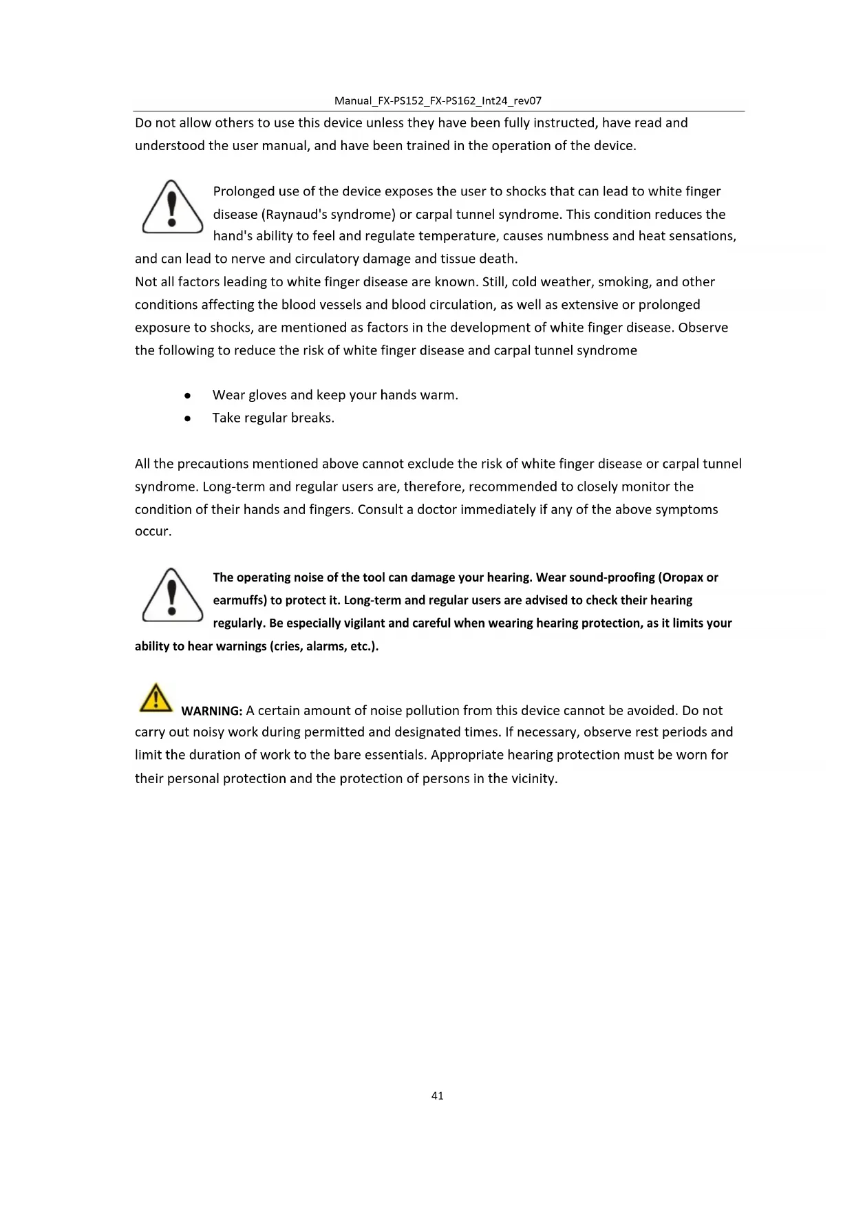
Mounting the metal blade
Steps:
- Place the key (1) in the hole on the gearhead.
- Remove the nut, the cover (4) and the upper distance washer (3) from the gear shaft.
- Place the metal sheet centrally on the lower Distance washer (2). Make sure that the marked side of the cutting blade is in contact with the disc (2).
- Slide the upper spacer disc (3) over the Gear shaft to the unmarked side of the metal sheet. Make sure that the lower (unmarked) side of the cutting blade is in contact with the upper spacer disc (3).
- Put on the silver ring = cover (4) and screw the union nut tight with the gear head locked (see point 1).

natural_image
Close-up of a black robotic brush with orange outline and mechanical lever (no text or symbols visible)
natural_image
Mechanical component diagram showing a curved mechanical assembly with a wheel and a separate circular component labeled '2' (no text or symbols beyond labels)
text_image
Diagram showing mechanical components with numbered parts labeled 3 and 4, including a highlighted section of a T-shaped component.
natural_image
Two-step diagram showing a tool being inserted into a mechanical component, with no visible text or symbols.Installation of the lawn trimmer (thread spool)
Step one:
Insert the key (1) into the hole in the gearhead so that the gear shaft is locked. Unscrew and remove the nut. Since it is a safety nut, please make sure that there is a left-hand thread here.
Step 2:
mount the lower spacer (here point 2, the same washer as above when mounting the knife 2) and install the thread spool on the gear shaft. The remaining accessories, such as the upper spacer washer/washer or the silver ring, are not required for mounting the thread spool! Then tighten it by hand.

text_image
2 1 Warning!Ensure that all components are correctly assembled and installed and that all screws are tightened.
FUEL AND 2-STROKE OIL
Use unleaded gasoline with 2-stroke engine oil in a 40:1 ratio. During the first few operations, a mixture ratio of 25:1 can be selected to initially lubricate all device parts optimally.
WARNING: Never use pure gasoline in your engine. This will cause permanent engine damage and voids the manufacturer's warranty for this product. Never use a fuel mixture that has been stored for more than 90 days.
WARNING: This must be a premium oil for 2-stroke air-cooled engines. We recommend the original FUXTEC 2T-oil "Made in Germany."
FUEL MIXTURE
Mix fuel with 2-stroke oil in a container provided for this purpose. Note the following the mixture table on the following page for the correct fuel/oil ratio. Shake the tank to ensure complete mixing.
| Gasoline | Two-stroke engine oil (40:1) | Gasoline | Two-stroke engine oil (40:1) |
| 1 liter | 0.025 liters | 5 liters | 0.125 liters |
| 2 liters | 0.050 liters | 10 liters | 0.250 liters |
WARNING: Failure to lubricate the device eliminates the liability of the device manufacturer.
Gasoline and oil must be mixed in the ratio 40:1.
Recommended fuel
It is recommended to use unleaded gasoline with an octane number of 90 # or higher to reduce carbon deposition in the combustion chamber. Do not use old or dirty gasoline. Keep the fuel tank dust-free and avoid water getting into the tank. Sometimes misfiring will occur under usual overload.
If the backfiring is heard under average load, we recommend replacing the gasoline. If the misfire is still present afterward, please contact an authorized workshop.

WARNING
text_image
Fuel filler cap max, filling level● Gasoline is highly flammable and can cause an explosion in case of sparks
- Refuel only in well-ventilated rooms and allow the engine to cool down before filling. Smoking and open fire, as well as any sparks, must be avoided during refueling
- Do not overfill the tank (see figure max. level)
● After refueling, check that the fuel filler cap is properly closed
● Avoid any spillage of gasoline
- Keep the device away from children
Gasoline with an ethanol content
The engine can be operated with E10 gasoline. However, do not use gasoline with a higher ethanol content than 10%.
29. Cold start of the engine
- Place the device on a firm and flat surface.
Slide the engine stop switch forward to position 1.

natural_image
Close-up of a black and orange handheld device with a red arrow indicating direction (no text or symbols)
natural_image
Close-up of a mechanical component with orange and black parts, showing a blue circular feature and a red arrow pointing to a green cable (no text or symbols visible)-
Move the choke lever upwards to "COLD START."
-
Press the carburetor pump about 8-10 times (until gasoline flows in the line)
-
Pull out the starter rope with a short-stroke until resistance is felt
(about 100mm). A continuous, mainly fast train will provide a strong spark, and the engine will respond after 2-3 trains.

natural_image
Close-up of a black industrial electric shock absorber with orange base, showing a hand holding the device and a red arrow indicating force direction (no text or symbols)
natural_image
Close-up of a hand adjusting a black industrial machine component with orange clamps (no visible text or symbols)-
Necessary: Set the choke lever to the "WARM START" position after the engine has responded and immediately pull the starter again until the engine starts. " see also video device start on our homepage."
-
Let the engine warm-up at idle for about 10 minutes
NOTE: If the device does not start after repeated attempts, refer to troubleshooting chapters.
NOTE: Always pull the starter cord straight out. Pulling the starter at an angle will cause the rope to rub against the eyelet. Pulling the starter at an angle can cause the starter cable to fray or break.
Always hold the starter handle firmly when the rope is pulled back. Never allow the rope to be thrown back from the pulled-out position. This could damage the starter device.
30. Warm start of the engine
- Place the device on a firm and flat surface.
- Slide the engine stop switch down
- Slide the choke to the "WARM START" position
- Pull out the starter rope with a short-stroke until resistance is felt
(about 100mm). A continuous high-speed train will provide a strong spark and start the engine
If the device does not start, please proceed again according to "Cold start of the engine
31. Stopping the device
Unlock the throttle. Let the device return to neutral. Move the engine stop switch on the handle upwards until the device stops. If it does not stop, pull out the spark plug connector in an emergency. Never leave the device unattended while it is running.
32. Trimming techniques
ADDITIONAL SAFETY INSTRUCTIONS
Before running your device, read notes in chapters 3 and 4 of this manual.
CAUTION
IF YOU are NOT familiar with the trimming techniques, practice with the DEVICE in the "STOP" position (turned off).
ALWAYS TRIM OR CUT AT HIGH ENGINE SPEEDS. Do not run the device slowly at the start or in trim mode.
ALWAYS MAKE DISTANCE IN THE WORKING AREA from cans, bottles, rocks, etc. Whirling objects can cause serious injury to users or bystanders and damage the device. If an object is accidentally knocked, immediately stop the DEVICE and check it. Never run the device with damaged or defective parts.
DO NOT use the device for any purpose other than trimming grass.
Never lift the nylon cutting head above knee height during operation.
Do not run the device on a slope if there is a chance of slipping or losing stability.
RELEASING THE NYLON THREAD

To release fresh thread, run the device at full throttle and tap the nylon cutting head onto the lawn. The thread releases automatically. The blade in the protective shield cuts off excess thread.

CAUTION: Remove grass deposits regularly to prevent overheating of the drive axle. Grass deposits occur when fibers of the weed become entangled around the shaft
under the protective shield. This prevents the shaft from cooling correctly. Remove grass deposits with a screwdriver or similar tool only when the device is switched off.
natural_image
Technical line drawing of a mechanical device with a downward arrow indicator (no text or symbols present)
natural_image
Technical line drawing of a mechanical assembly with an arrow indicating a component (no text or symbols present)When the device is appropriately equipped with a protective shield and nylon cutting head, your device will trim unsightly weeds and large diameter tall grass in areas along fences, walls, land, and around trees.
NOTE: Pay particular attention when trimming on brick or stone walls, etc., where rapid weed wear will occur.
TRIM MORE ACCURATELY
Swing the trimmer's nylon cutting head horizontally from side to side. Do not tilt the nylon cutting head while working. For correct cutting height, trim in a test area beforehand. Keep nylon cutting head at the same level for even depth of cut.
natural_image
Diagram of a mechanical device emitting particles or smoke, with arrows indicating direction (no text or symbols)TRIMMING AROUND TREES
Trim around logs with a slow approach; the thread should not collide with the log. Walk around the tree from left to right—approach grass or weeds with the tip of the thread.
33. Replacing Nylon Thread
The model FX-PS152 comes with an EASY Fit nylon thread head, which does not need to be disassembled in a complicated way.
You turn the bobbin head (orange) until the arrow markings match, and the hole is visible throughout.
You simply push the desired length of thread through and wind the thread clockwise. Therefore also EASY FIT - filling up the thread without disassembling the bobbin

natural_image
Close-up of a black plastic component with an orange plastic cap and red directional arrows indicating rotation or movement (no text or symbols)34. Maintenance plan
Regular checks and adjustments must be made to ensure that the gasoline engine maintains its performance. Periodic maintenance also provides a long service life. See the following table for the regular maintenance cycle.
| Maintenance cycleComponent | Each use | Every month or 10h | Every 3 months or 25h | Every 6 months or 50h | Every 12 months or 100h | Every 2 years or 300h | |
| Air filter | Check | ■ | |||||
| Clean up | ■a | ||||||
| Spark plug | Check & adjust | ■ | |||||
| Exchange | ■ | ||||||
| Spark plug connector (optional) | Clean up | ■ | |||||
| Cooling fins | Audit | ■ | |||||
| connecting elements such as screws and nuts | Check (tighten if necessary) | ■ | |||||
| Coupling | Audit | ■b | |||||
| Idle speed | Check and adjust | ■b | |||||
| Valve clearance | Check and adjust | ■b | |||||
| Combustion chamber | Clean up | 300 h after that | |||||
| Fuel | Check | ■ | |||||
| Fuel tank | Check | ■ | |||||
| Fuel line | Check | Every x years (replace if necessary) | |||||
WARNING

a. Increase maintenance intervals if working in dusty environments.
b. All maintenance work - except for that listed in the operating manual - must be carried out at regular intervals.
Work must be carried out by qualified maintenance personnel
Cleaning the air filter
CAUTION: Never run the engine without the air filter.
A dirty air filter puts pressure on engine performance, increases fuel consumption, and makes starting
more difficult. If you notice a loss of engine power:
1 Remove the screw on the filter cover and take out the filter.
2 Clean the filter with soap and water. Never use gasoline or benzene!
3 Let the filtered air dry.
4 Put the filter back in place and fasten the filter cover with the screw.

natural_image
Close-up of a mechanical device with orange handle and black housing, showing internal components (no text or symbols visible)
natural_image
Close-up of a hand adjusting an orange FUNTEC-branded device with black casing and orange handle (no visible text or symbols)Spark plug maintenance
To ensure the normal operation of the engine, the ignition distance of 0.6 -0.7mm must be maintained and must be free of carbon deposits. Always carry out the following steps with the engine switched off:
-
Carefully remove the spark plug connector. Do not pull on the cable but directly on the plug
-
Use the spark plug wrench supplied to unscrew the spark plug
-
Visually check the spark plug for damage and electrode burn-off,
Remove the carbon deposits
-
Check the gap with a feeler gauge and bend the electrode to the correct distance of 0.6 to 0.7mm
-
Check the spark plug washer and tighten the spark plug with a torque of 12-15 Nm
-
Fit the ignition cap back onto the spark plug
text_image
0.6~0.7mmWARNING

The spark plug must be screwed down tightly; otherwise, the engine runs hot and is damaged.
Sharpen the shielded knife
- Remove cutting blade (E) from a protective shield (F).
- Clamp the knife in a vice. Sharpen the knife with a flat-file.
Please make sure that you maintain the angle of the cutting
edge. Only move the sharpening knife in one direction during the sharpening process.
text_image
nt-file. tting F E35. Storage of the device

WARNING: Failure to follow these steps may result in the formation of deposits in the carburetor. This will make starting difficult and cause permanent damage
- Perform all general maintenance as described in the maintenance section of your user manual are recommended.
- Clean the exterior of the device, drive axle, protective shield, and nylon cutting head.
- Drain fuel from the fuel tank.
- After draining fuel, start the engine.
- Let the device run in neutral until the device stops on its own. This will clean the carburetor of fuel.
- Let the device cool down (about 5 minutes).
- Use a spark plug wrench, remove the spark plug.
- Pour 1 teaspoon of clean 2-stroke oil into the combustion chamber. Pull the starter cord slowly several times to coat internal components. Replace the spark plug.
- Store the device in a cool, dry place away from any ignition source such as an oil burner, water heater, etc.
TRANSPORT PROTECTION
Make sure that the device is well-secured during transport to avoid fuel loss, damage, or injury. Install transport protection for metal sheets during transport and storage
36. Troubleshooting
- Difficulties during commissioning
| Situation | Cause | Solution | |
| No ignition spark | Spark plug | Carbon deposit between the diodes of the spark plug | Clean the spark plug. Adjust the gap 0.6~0.7mm, replace the spark plug |
| other | Ignition coil defective flywheel magnet too weak | Replace the ignition coil or flywheel | |
| Weak ignition spark | Compression | Too much gasoline in the combustion chamber, bad fuel or water in the tank | Remove the spark plug and allow to dry, replace fuel. |
| The carburetor does not pump oil anymore. | Oil line blocked | Cleaning the carburetor and cleaning the pipes | |
| Normal oil supply but weak compression | Piston rings worn, spark plug not screwed down, cylinder head not tight wrong valve clearance or ignition timing. | Replace screw tight replace or adjust | |
| Normal oil supply and proper ignition spark | Poor contact between ignition cap and spark plug | Replace or check | |
- Difficulties during operation
| Situation | Cause | Solution |
| The engine does not reach the speed | Choke is in "COLD START" position, an exhaust system is blocked no air supply, moving elements worn, ignition spark weak too large valve clearance, cylinder head sooty | Open choke, replace exhaust system Check or replace ignition coil, adjust flywheel, spark plug |
| Operating materials are leaking | Lines to carburetor blocked Spark plug spacing incorrect | Replace lines and carburetor Adjust gap dimension |
| Motor-Noises | Wrong choke position,Camshaft damaged | Check/replace camshaft |
| Carburetor leaking | Failure of the check valve on the tank cap | Replace the fuel filler cap |
| Carburetor gasket is worn out | Replace carburetor or gasket |

If no troubleshooting solves the problem, contact your dealer or the manufacturer directly. Only use original parts approved by the manufacturer. Otherwise, there is a risk of danger.
37. Customer Service
Have your purchased device repaired only by qualified personnel and only with original spare parts. This will ensure that the safety of the device is maintained.
Please contact the manufacturer FUXTEC GmbH directly at any time regarding maintenance work and procurement of spare parts at www.fuxtec.co.uk
38. Warranty
The warranty period is 24 months from the date of purchase. Please keep your proof of purchase in a safe place. Excluded from the warranty are wearing parts and damage caused by improper use, use of force, technical modifications, use of incorrect accessories or non-original spare parts, and repair attempts by non-qualified personnel. Warranty repairs may only be carried out by authorized specialist dealers.
39. Disposal note
Please contact your local municipality for the disposal of the device. Please dispose of all operating materials such as gasoline and oil in advance.
40. EU Declaration of Conformity
We hereby declare,
FUXTEC GMBH
CAPPING ROAD 69, 71083 HERRENBERG, GERMANY
that the device described below, by its design and construction and in the version marketed by us, complies with the relevant essential health and safety requirements of the EC directives.
Designation of the device:
Gasoline motor scythe/lawn trimmer
Engine type:
FX-PS152 / FXPS162
Trademark:
FUXTEC
Power consumption/displacement
Measured sound power level
LWA = 107.7dB
Guaranteed sound power level
LWA=113dB
Conformity procedure 2000/14/EC
according to Annex V
EC devise straightening thread 2006/42/EC
Relevant EC straightening thread:
EC directive on electromagnetic compatibility (EMC) 2004/108/EC
EC-directive thread Noise emission (2000/14/EWG & 2005/88/EC)
Applied harmonized
EN ISO 11806-1
Standards:
EN ISO 14982
Manufacturer signature/date:
C. Jille
L. Zirkler, 30.11.2022
Name and address of the person
Leongard Zirkler
authorized to compile the
FUXTEC GMBH - KAPPSTRAße 69, 71083 HERRENBERG, GERMANY
technical documentation
established within the
Community
VERSION FRANCAISE
MODE D'EMPLOI ORIGINAL
natural_image
Black and orange FUTECY manual lawn brush tool with attached lever and handle (no text or symbols visible)CE
natural_image
Line drawing of a person wearing a hard hat and safety harness, adjusting a device (no text or symbols)
natural_image
Illustration of a person wearing a hard hat and safety harness (no text or symbols)
natural_image
Line drawing of a worker in protective gear using a handheld tool (no text or symbols)
natural_image
Line drawing of a person wearing safety harness and helmet, holding a rope (no text or symbols)
natural_image
Person holding a mechanical device with attached wires, black and white photo (no visible text or symbols)natural_image
Technical line drawing of a mechanical assembly with no visible text or symbolsnatural_image
Mechanical assembly diagram showing a lever mechanism with a black base and arrow indicating motion (no text or symbols)natural_image
Close-up of a hand holding a metallic mechanical component with arrows indicating direction (no text or symbols visible)natural_image
Hand holding a metallic tool with a handle, against a plain white background (no text or symbols visible)natural_image
Close-up of a black robotic brush tool with orange frame and mechanical handle (no text or symbols visible)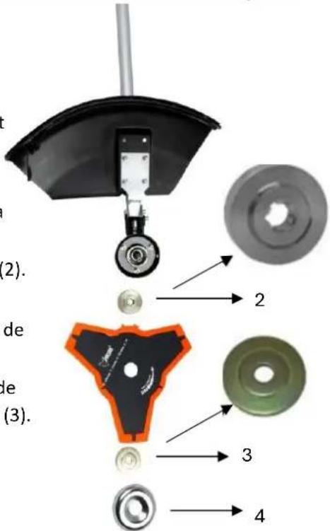
natural_image
Close-up of a mechanical tool with a black and orange blade, showing a turning mechanism (no text or symbols visible)
natural_image
Close-up of hands installing a mechanical component with a wrench, no visible text or symbolstext_image
Attention! 2 1natural_image
Close-up of a black and orange handheld device with a red arrow indicating motion (no text or symbols)
natural_image
Close-up of a mechanical component with orange and black parts, showing a red arrow pointing to a yellow-green cable or connector (no text or symbols visible)natural_image
Close-up of a black and orange electric shock absorber with a hand adjusting its body (no text or symbols visible)
natural_image
Close-up of a hand adjusting a black industrial machine with orange clamps and a red arrow pointing to the component (no visible text or symbols)natural_image
Technical line drawing of a naval gun on a ship deck with a downward arrow indicating force or impact (no text or symbols present)
natural_image
Technical line drawing of a mechanical assembly with an arrow indicating a component (no text or symbols present)natural_image
Diagram of a mechanical fan or impeller with motion arrows indicating airflow or movement (no text or symbols)natural_image
Close-up of a black plastic component with an orange plastic cap and red directional arrows indicating rotation or flow (no text or symbols)54. Plan de maintenance
natural_image
Close-up of a hand adjusting a black FUTTEC device with orange handle (no visible text or symbols)
natural_image
Disassembled electric shock absorber with black housing and orange valve, shown from two views (no text or symbols visible)text_image
0.6~0.7mm
AVERTISSEMENT
natural_image
Close-up of a mechanical component with labeled parts F and E, showing internal components and a ruler-like scale (no text or symbols beyond labels)55. Stockage de la machine

natural_image
Black and orange FUTECY manual lawn brush tool with attached lever and handle (no text or symbols visible)CE
natural_image
Person wearing safety harness and helmet, handling a device with chains (no visible text or symbols)
text_image
les treaselle (1)La tracolla
natural_image
Technical line drawing of a mechanical assembly with no visible text or symbolsnatural_image
Mechanical assembly diagram showing a lever mechanism with a handle and base mount (no text or symbols)natural_image
Close-up of a hand holding a metallic mechanical component with arrows indicating direction (no text or symbols visible)natural_image
Hand holding a metallic tool with a handle, against a plain white background (no text or symbols visible)natural_image
Close-up of a black and orange robotic brush tool with a metallic handle (no text or symbols visible)
natural_image
Mechanical assembly diagram showing a wheel-mounted component with a separate circular part labeled '2' (no text or symbols beyond labels)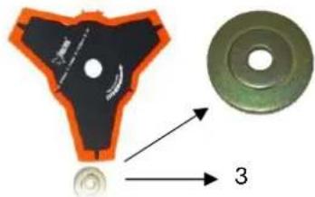
text_image
Technical diagram showing a mechanical component with labeled parts and directional arrows indicating flow or assembly.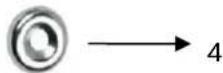

natural_image
Close-up of a mechanical tool with a black blade and orange base, showing a hand holding the component (no text or symbols visible)
natural_image
Close-up of hands using a wrench to adjust a mechanical component with a black base and orange outline (no text or symbols visible)natural_image
Close-up of a black handheld device with an orange handle and red arrow indicating a downward motion (no text or symbols)
natural_image
Close-up of a mechanical component with orange tool handle and red arrow indicating a step (no visible text or symbols)
natural_image
Close-up of an orange automotive component with a black plastic container and wiring, no visible text or symbolsnatural_image
Close-up of a black and orange electric shock absorber with a hand adjusting its internal components (no text or symbols visible)
natural_image
Close-up of a hand adjusting a black industrial machine component with orange clamps (no visible text or symbols)natural_image
Diagram of a naval gun firing from a ship deck, showing blade and gear components (no text or symbols)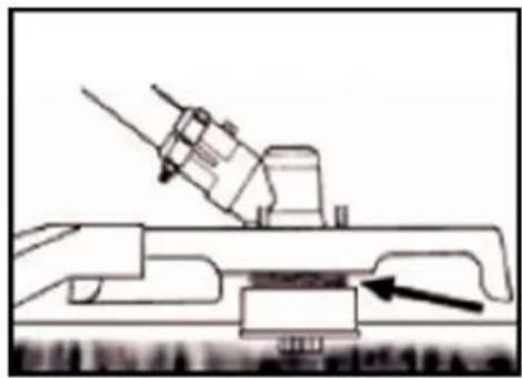
natural_image
Technical line drawing of a mechanical assembly with an arrow indicating a component (no text or symbols present)natural_image
Diagram of a mechanical device emitting particles or smoke, with no visible text or symbolsTAGLIARE INTORNO GLI ALBERI
natural_image
Close-up of a black plastic component with an orange plastic cap, showing red directional arrows indicating flow or movement (no text or symbols)natural_image
Close-up of a black and orange FUTED spray gun with a hand adjusting its grip (no visible text or symbols)
natural_image
Close-up of a mechanical device with black housing and orange pump feet (no visible text or symbols)
natural_image
Close-up of a mechanical component with a circular dial and rectangular housing (no visible text or symbols)text_image
0.6~0.7mmAVVERTENZE
natural_image
Close-up of a mechanical component with labeled parts (F, E) and a ruler, showing no readable text or symbols beyond labels.natural_image
Black and orange FUTECY manual lawn brush tool with attached lever and handle (no text or symbols visible)CE
natural_image
Black-and-white photo of a person using a tool to lift a large cylindrical object, with no visible text or symbols.
natural_image
Three technical illustrations of a worker wearing safety harnesses and holding equipment, no text or symbols present.La correa
natural_image
Technical line drawing of a mechanical assembly with no visible text or symbolsnatural_image
Mechanical assembly diagram showing a lever mechanism with a handle and base mount (no text or symbols)natural_image
Close-up of a hand holding a metallic mechanical component with arrows indicating direction (no text or symbols visible)natural_image
Hand holding a metallic tool with a handle, against a plain white background (no text or symbols visible)natural_image
Close-up of a black and orange robotic brush tool with a circular base, mounted on a metal rod (no text or symbols visible)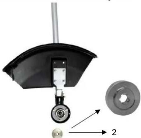
natural_image
Mechanical component diagram showing a curved mechanical part with a central hub and a separate circular component labeled '2' (no text or symbols beyond labels)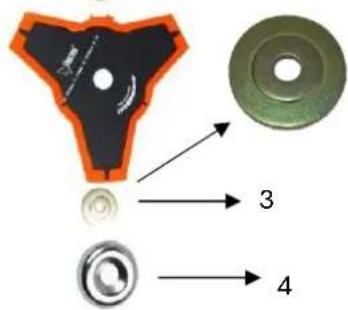
text_image
Diagram showing mechanical components with numbered parts labeled 3 and 4, including a highlighted section of a T-shaped component.
natural_image
Two-step diagram showing a tool being inserted into a mechanical component, with no visible text or symbols.MEZCLA DE COMBUSTIBLE
natural_image
Close-up of a black handheld device with an orange button and red arrow indicating a downward motion (no text or symbols)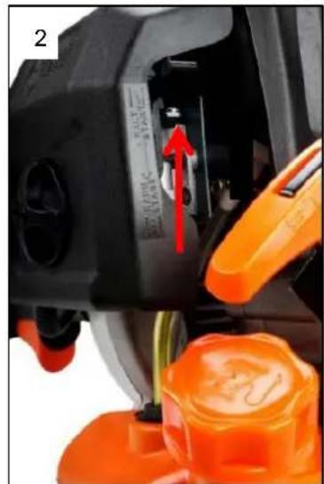
natural_image
Close-up of a mechanical component with orange components and a red arrow indicating a specific part (no visible text or symbols)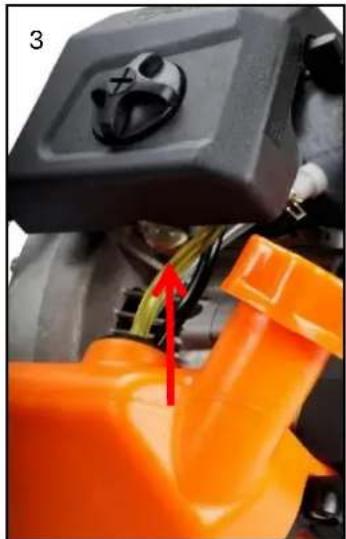
natural_image
Close-up of an orange automotive engine component with a black plastic housing and wiring, no visible text or symbolsnatural_image
Close-up of a black electric shock absorber with orange base and orange handle, being adjusted by a red tool (no text or symbols visible)
natural_image
Close-up of a hand adjusting a black industrial machine component with orange clamps (no visible text or symbols)natural_image
Illustration of a naval gun firing from a ship deck, with no visible text or symbols
natural_image
Technical line drawing of a mechanical assembly with an arrow indicating a component (no text or symbols present)natural_image
Diagram of a mechanical device emitting smoke or vapor, with arrows indicating direction (no text or symbols)CORTANDO ALREDEDOR DE LOS ÁRBOLES
natural_image
Close-up of a black plastic component with an orange plastic cap and red directional arrows indicating rotation or flow (no text or symbols)natural_image
Close-up of a hand adjusting an orange FUTTEC-branded device with a black control panel (no visible text or symbols on the device itself)
natural_image
Close-up of a black industrial machine with orange handle and internal components (no visible text or symbols)
natural_image
Close-up of a black plastic mechanical component with a circular dial and rectangular housing (no visible text or symbols)natural_image
Close-up of a yellow-orange surface with a ruler and a black triangular ruler beside it, no visible text or symbols.natural_image
Black and orange FUTECY manual lawn brush tool with attached lever and handle (no text or symbols visible)CE
text_image
15m(50ft)MANTENHA SEMPRE A 15 METROS DE DISTÂNCIA DE OUTRA PESSOA DISTÂNCIA

O NÍVEL DE RUÍDO GARANTIDO ESTÁ EM CONFORMIDADE COM AS DIRETRIZES LEGAIS DE RUÍDO

natural_image
Technical line drawing of a mechanical assembly with no visible text or symbolsnatural_image
Mechanical assembly diagram showing a lever mechanism with a black base and arrow indicating direction (no text or symbols)
natural_image
Close-up of a hand holding a metallic cylindrical tool with a knob, no visible text or symbols
natural_image
Hand holding a metallic tool with a handle, against a plain white background (no text or symbols visible)natural_image
Close-up of a black robotic brush with orange outline and mechanical lever (no text or symbols visible)
natural_image
Mechanical component diagram showing a curved mechanical assembly with a wheel and a separate circular component labeled '2' (no text or symbols beyond labels)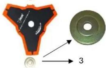
text_image
Diagram showing a mechanical component with an orange outline and a green circular component, labeled with number 3.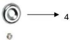

natural_image
Two-step diagram showing a mechanical tool being inserted into a black plastic component, with hands adjusting the tool (no text or symbols present)natural_image
Close-up of a black and orange handheld device with a red arrow indicating motion or change (no text or symbols visible)
natural_image
Close-up of a mechanical component with orange and black parts, showing a red arrow pointing to a yellow-green connector (no text or symbols visible)natural_image
Close-up of a black and orange electric shock absorber with a hand adjusting its top panel, showing a red arrow indicating the tool (no text or symbols visible)
natural_image
Close-up of a hand adjusting a black industrial machine component with orange clamps (no visible text or symbols)natural_image
Illustration of a naval gun firing from a ship deck, with no visible text or symbols
natural_image
Technical line drawing of a mechanical assembly with an arrow indicating a component (no text or symbols present)natural_image
Diagram of a mechanical device emitting smoke or vapor, with arrows indicating direction (no text or symbols)CORTE EM TORNO DE ÁRVORES
natural_image
Close-up of a black plastic component with an orange plastic cover and red directional arrows indicating motion or flow (no text or symbols)natural_image
Close-up of a hand adjusting an orange FUNTEC-branded device with black buttons and orange handle (no visible text or symbols)
natural_image
Close-up of a black and orange industrial device with internal components, showing internal structure and housing (no text or symbols visible)text_image
0.6~0.7mm aADVERTÊNCIA

natural_image
Exterior view of a manual grass meter with black body, orange handle, and metal rod (no text or symbols visible)CE
natural_image
Person using a tool to lift a large object, with a magnified inset showing the worker's helmet and seatbelt (no text or symbols visible)
natural_image
Three technical illustrations of a worker wearing safety harnesses and holding a tool, with no visible text or symbols.natural_image
Technical line drawing of a mechanical assembly with no visible text or symbolsnatural_image
Mechanical assembly diagram showing a lever mechanism with a black base and arrow indicating direction (no text or symbols)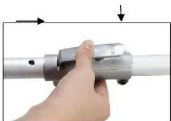
natural_image
Close-up of a hand holding a metallic cylindrical tool with a small component, no visible text or symbols
natural_image
Hand holding a metallic tool with a handle, against a plain white background (no text or symbols visible)text_image
Exploded view diagram of a mechanical component with numbered parts labeled 2, 3, and 4
natural_image
Two-step diagram showing a mechanical tool and its assembly with a circular component being inserted (no text or symbols present)Montage van de Rasentrimmers (Fadenspule)
Stap 1:
natural_image
Close-up of a black and orange handheld device with a red arrow indicating motion or change (no text or symbols visible)
natural_image
Close-up of a mechanical component with orange and black parts, showing a red arrow pointing to a yellow-green connector (no text or symbols visible)natural_image
Close-up of a black and orange electric shock absorber with a hand adjusting its top panel, showing a red arrow indicating the tool (no text or symbols visible)
natural_image
Close-up of a hand adjusting a black industrial machine component with orange clamps (no visible text or symbols)natural_image
Illustration of a naval gun firing from a ship deck, with no visible text or symbols
natural_image
Technical line drawing of a mechanical assembly with an arrow indicating a component (no text or symbols present)natural_image
Diagram of a mechanical device emitting particles or smoke, with arrows indicating direction (no text or symbols)SNOEIEN ROND BOMEN
natural_image
Close-up of a black plastic component with an orange plastic cap and red directional arrows indicating flow or movement (no text or symbols)natural_image
Close-up of a hand adjusting a FIXTEC-branded electronic device with orange handle (no visible text or symbols)
natural_image
Close-up of a black industrial device with orange base and orange handle (no visible text or symbols)
natural_image
Close-up of a black plastic mechanical component with a circular dial and rectangular housing (no visible text or symbols)Bougie onderhoud
text_image
0.6~0.7mmWAARSCHUWING

text_image
been platte t. chting. F EBESCHERMING TEGEN TRANSPORT
natural_image
Black and orange manual lawn brush tool with attached lever and head (no visible text or symbols)CE
text_image
15m(50ft)HÅLL ALLTID 15 METERS AVSTÅND FRÅN EN ANNAN PERSON AVSTÅND

DEN GARANTERADE LJUDNIVÅN ÖVERENSSTÄMMER MED DE LAGSTADGADE BULLERRIKTLINJERNA

VARNING FÖR FLYGANDE FÖREMÅL
 | INGEN RÖKNING OCH ÖPPEN ELD PÅ ENHETEN |
 | VARNING:FARA MED HETA KOMPONENTER |
 | STÄNG AV ALWAYS-MASKINEN OCH SE TILL ATTSKÄRVERKTYGET ÄR STOPPAT INNAN DU RENGÖR, TAR BORTELLER JUSTERAR DET. |
 | VARNING:AVGASER FRÅN DENNA PRODUKT INGÅRKEMIKALIER SOM ORSAKAR CANCER, FOSTERSKADOROCH KAN LEDA TILL MER |
 | VARNING! BYT ALDRIG MASKIN. FELAKTIG ANVÄNDNING AVMASKINEN KAN ORSAKA ALLVARLIGA ELLER DÖDLIGAPERSONSKADOR. |
 | VARNING! BRÄNNBARA MATERIAL |
 | MAXIMAL SPINDELHASTIGHET (GRÄSTRIMMER): 6600 RPM |
 | MAXIMAL SPINDELHASTIGHET (RÖJSÅG): 7100 RPM |
natural_image
Person wearing safety harness and hard hat, handling a device with chains (no visible text or symbols)
natural_image
Three technical illustrations of a worker wearing safety harnesses and holding a tool, demonstrating different methods (no text or symbols present)natural_image
Technical line drawing of a mechanical assembly with no visible text or symbolsnatural_image
Close-up of a metallic mechanical component with a lever and base mount, showing an arrow indicating motion (no text or symbols)
natural_image
Close-up of a hand holding a metallic mechanical component with a pull rod (no text or symbols visible)
natural_image
Hand holding a handheld tool against a plain background (no text or symbols visible)text_image
Exploded view diagram of a mechanical assembly with numbered parts labeled 2, 3, and 4
natural_image
Two-step diagram showing a mechanical tool and a close-up of a mechanical component being processed, with no visible text or symbols.text_image
2 1 Varning!natural_image
Close-up of a black and orange handheld device with a red arrow indicating motion or change (no text or symbols visible)
natural_image
Close-up of a mechanical component with orange and black parts, showing a red arrow pointing to a yellow-green connector (no text or symbols visible)natural_image
Close-up of a black and orange electric shock absorber with a hand adjusting its top panel, showing a red arrow indicating the tool (no text or symbols visible)
natural_image
Close-up of a hand adjusting an orange industrial machine component with a red arrow indicating the adjustment (no visible text or symbols)OM DU INTE ÄR BEKANT MED TRIMTEKNIKERNA, ÖVA MED MASKINEN I "STOPP"-LÄGE.
natural_image
Illustration of a naval gun firing from a ship deck, with no visible text or symbols
natural_image
Technical line drawing of a mechanical assembly with an arrow indicating a component (no text or symbols present)natural_image
Diagram of a wind turbine blade with motion arrows indicating airflow or movement (no text or symbols)BESKÄRNING RUNT TRÄD
natural_image
Close-up of a black plastic component with an orange plastic cover and red directional arrows indicating motion (no text or symbols)natural_image
Close-up of a hand adjusting a black FIXTEC device with orange handle (no visible text or symbols)
natural_image
Close-up of a black and orange industrial device with internal components, showing no visible text or symbols.text_image
0.6~0.7mmWARNING

POLSKA WERSJA JEZYKOWA
ORYGINALNA INSTRUKCJA OBSŁUGI
natural_image
Black and orange manual lawn brush tool with attached lever and head (no visible text or symbols)CE
natural_image
Technical line drawing of a mechanical device with no visible text or symbolsnatural_image
Mechanical assembly diagram showing a lever mechanism with a black base and arrow indicating direction (no text or symbols)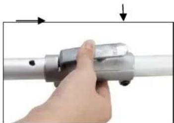
natural_image
Close-up of a hand holding a metallic cylindrical tool with a knob, no visible text or symbols
natural_image
Hand holding a metallic tool with a handle, against a plain white background (no text or symbols visible)text_image
Exploded view diagram of a mechanical assembly with numbered parts for identification
natural_image
Two-step diagram showing a mechanical tool being inserted into a motor, with no visible text or symbols.natural_image
Close-up of a black and orange handheld device with a red arrow indicating motion or change (no text or symbols visible)
natural_image
Close-up of a mechanical component with orange and black parts, showing a red arrow pointing to a yellow-green connector (no text or symbols visible)natural_image
Close-up of a black and orange electric shock absorber with a hand adjusting its top panel, showing a red arrow indicating the tool (no text or symbols visible)
natural_image
Close-up of a hand adjusting an orange industrial machine component with a red arrow pointing to the component (no visible text or symbols)natural_image
Illustration of a naval gun firing from a ship deck, with no visible text or symbols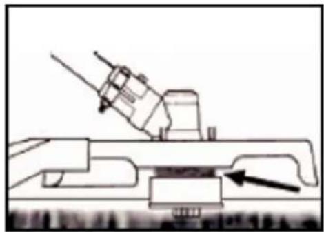
natural_image
Technical line drawing of a mechanical assembly with an arrow indicating a component (no text or symbols present)natural_image
Diagram of a mechanical device emitting smoke or vapor, with arrows indicating direction (no text or symbols)PRZYCINANIE WOKÓŁ DRZEW
natural_image
Close-up of a mechanical component with orange and black surfaces, no visible text or symbolsnatural_image
Close-up of a hand adjusting a black and orange FAXTEC device component (no visible text or symbols)