Piuma Plus U16 - Bike Argento - Free user manual and instructions
Find the device manual for free Piuma Plus U16 Argento in PDF.
| Product type | Pedal-assisted bicycle (EPAC) |
| Brand | Argento |
| Model | Piuma Plus U16 |
| Frame | Foldable 6061 aluminum |
| Motor | Xofo 36 V 250 W brushless (rear) |
| Battery | Li-Ion 36 V 10.4 Ah 374 Wh, external and removable |
| Estimated range | Varies with use (weight, assistance, terrain) |
| Charging time | 4 to 6 hours |
| Charger | Input 100-240 V AC, output 42 V DC 2.0 A |
| Top speed | 25 km/h (assistance cuts off at this speed) |
| Drive | 7-speed chain, Shimano derailleur |
| Brakes | Mechanical disc brakes front and rear with brake sensor |
| Wheels | 20 inches front and rear |
| Tires | Tires with recommended pressure on sidewall |
| Display | LED King-Meter 790 (shows assistance level and battery) |
| Lighting | Front and rear LED lights |
| Weight | Approximately 23 kg |
| Maximum load (bike) | 100 kg |
| Maximum load (rear rack) | 25 kg |
| Folding | Foldable frame, telescopic and foldable stem |
| Usage | Outdoor, roads and cycle paths, max slope 10 % |
| Operating temperature | 0°C to +40°C |
| Maintenance | Clean with water and soft cloth, battery removed |
| Warranty | See terms and conditions at www.argentobike.it |
Frequently Asked Questions - Piuma Plus U16 Argento
User questions about Piuma Plus U16 Argento
0 question about this device. Answer the ones you know or ask your own.
Ask a new question about this device
Download the instructions for your Bike in PDF format for free! Find your manual Piuma Plus U16 - Argento and take your electronic device back in hand. On this page are published all the documents necessary for the use of your device. Piuma Plus U16 by Argento.
USER MANUAL Piuma Plus U16 Argento
natural_image
Abstract green circular logo with white leaf-like shapes (no text or symbols)ARGENTO
E-MOBILITY®
e-bikes
user manual
English......02
Italiano 48
Español.... 96
Français....144
Deutsch......192
Polski....239
Čeština 286
Slovenčina 331
Slovenščina ....377
Nederlands 422
This manual is valid for the following electrically power assisted cycles (EPAC)
Piuma
Piuma +
Piuma-S
Piuma-S +
User manual
Instructions translated from the original Italian
Thank you for choosing this product.
For information, technical support, assistance or to consult the general terms of the
warranty, please contact your dealer or visit www.argentobike.it
- Introduction
- Warnings on use and safety
- Product overview
- Technical data sheet
- Assembly
- Display
- Battery
- First use
- Storage, maintenance and cleaning
- Liability and general terms of warranty
- Information on disposal
1. Introduction
Overview
This manual is an integral and essential part of the electrically power assisted cycle (EPAC).
Before using the bike for the first time, it is essential that users read, understand and strictly observe the requirements outlined below.
M.T. Distribution shall not be liable for any damages caused and is in no way responsible for damages caused to property or persons when:
- the item is used incorrectly or in a manner that does not comply with the instructions of the user guide;
- following purchase, the item is modified or tampered with in all or some of its components.
In the interest of technological development, the manufacturer reserves the right to modify the product in question without prior notice and without automatically updating this manual. For further information and to consult any updated versions of the manual, please visit www.argentobike.it
After-sales service
For any problem or request for clarification, please do not hesitate to contact the after-sales service team of your authorised dealer who has expertise and specialist knowledge and access to specific tools and original spare parts.
Legal note for use
Check and observe the highway code and local road regulations in force for cyclists on any restrictions for riders, who may use the product, and on the use of this type of product.
Symbols identifying the safety warnings
To identify the safety messages in the manual, the following warning symbols will be used which serve to draw the reader's/user's attention in order to ensure that the electrically power assisted cycle is used correctly and safely.
Caution
Highlights the rules to follow to prevent damage to the electrically power assisted cycle and/or prevent hazardous situations from arising.
Residual risks
Highlights the presence of hazards which cause residual risks to which the user must pay attention to avoid injury or damage to property.
2. Warnings on use and safety
General safety rules
Even if you are already familiar with the use of an electrically power assisted cycle, the instructions given below must be followed and the general guidelines for operating a motorised vehicle must also be observed.
It is important to take the time required to learn the basics of using the bike to avoid serious injury which could occur when first using it. Contact your dealer for advice on how to use the bike correctly or indications on contacting a suitable training organisation.
The company assumes no direct or indirect responsibility arising from misuse of the bike, failure to comply with both the highway code and the instructions in the manual, accidents or disputes caused by failure to comply with regulations or illegal actions.
This product must be used for recreational purposes. It cannot be used by more than one person at a time and must not be used to transport passengers.
Do not modify the intended use of the vehicle in any way. The item is not suitable for stunts, competitions, transporting objects, towing other vehicles or trailers.
The A-weighted emission sound pressure level at the rider's ear is less than 70 dB(A).

Using the electrically power assisted cycle
All users must have read and understood the instructions and information outlined in the manual.
If, during assembly, any factory defects are detected, certain steps are unclear or issues with assembly or adjustments occur, do not ride the vehicle and contact your dealer or visit www.argentobike.it for technical support.
Risks associated with using the electrically power assisted cycle
Despite the application of safety devices, to ensure safe use of the electrically power assisted cycle, all the safety provisions reported in this manual must be observed.
Always maintain concentration while riding the bike and do not underestimate the residual risks connected with use of the electrically power assisted cycle.
Responsibility
The rider is required to use the electrically power assisted cycle with utmost diligence and in full compliance with the road regulations and all cycling rules in force in the country of use.
It is important to bear in mind that when out in a public space or on the road, even when the instructions in the manual are observed to the letter, the rider is not immune to injury caused
by infractions or inappropriate actions taken towards other vehicles, obstacles or persons. Misuse of the item or non-compliance with the instructions provided in this manual may cause severe injury.
Riders must also ensure that the electrically power assisted cycle is kept clean, in perfect working order and serviced. They must diligently carry out the safety checks which are their responsibility, as well as preserve all the documentation about product maintenance.
Riders must carefully assess any weather conditions which could make it potentially dangerous to use the electrically power assisted cycle.
This product is a vehicle, therefore, the faster is it goes, the longer the braking distance required. We, therefore, recommend moderating your speed and maintaining an adequate braking distance if you are riding in adverse weather conditions and/or heavy traffic.
The braking distance increases on wet, slippery, muddy or icy roads and the tyre grip decreases significantly with the risk of the wheels skidding and loss of balance compared to dry roads.
It is, therefore, essential to ride the bike with greater care, maintain a suitable speed and safety distance from other vehicles or pedestrians.
Take extra care when riding on unfamiliar roads.
For your safety, we recommend wearing suitable protective equipment (helmet, knee and elbow pads) to protect yourself from any falls or injuries while riding the bike. When allowing others to use the bike, ensure that the rider wears the safety equipment and explain how to operate the vehicle. To avoid injury, do not allow other persons to use the item if they do not know how to use it.
Wear shoes before using the item.
The bike has been designed to allow the load of a maximum overall weight (rider and any load being carried) that does not exceed the value indicated in the product data sheet.
Avoid using the product, under all circumstances, if the total load transported exceeds the recommended weight to avoid the risk of damaging the integrity of the structural and electronic components of the bike.
The electrically power assisted cycle (EPAC), as specified in the provisions of the current reference standard EN 15194, is a means of transport intended to transport one person only.
The transport of a passenger is only permitted within the framework of the regulations in force in the country where it is ridden regarding: the minimum age of the rider, maximum age of the passenger transported, provision of legally approved and authorised passenger transport devices.
It is the user's responsibility to ascertain the suitability of the devices used for passenger transport in terms of construction characteristics, safety systems, anchoring systems and their installation and assembly on the electrically power assisted cycle based on its structure and within the permitted load limits (maximum load supported by the bike and by the luggage rack supplied, if present).
The user is also responsible for the provision and installation of devices used for the transport of objects and animals (e.g. luggage racks, luggage bags, storage baskets, etc.) in compliance with the legally approved and authorised provisions in the country of use and the limitations of the structure within the permitted load limits (maximum load supported by the bike and by the luggage rack supplied, if present).

CAUTION
The installation of accessories and equipment on the bike, not only affect the performance of the bike and how it is used, but can also cause damage if they are unsuitable, thus compromising correct operation and safety conditions during use.
For information on the supply and installation of equipment deemed suitable for the bike, please contact your authorised dealer or specialised operators.
Warnings for users
- The electrically power assisted cycle can only be used by adults and skilled teenagers.
- Do not take alcohol or drugs before riding the electrically power assisted cycle.
- This electrically power assisted cycle model is designed and built for outdoor use on public roads or cycle tracks.
- Do not attempt to make the electrically power assisted cycle exceed the performance levels for which it was designed; do not ride on surfaces with a slope greater than 10%, on uneven and rough ground (bumpy road surfaces, with potholes, depressions, obstacles).
- Never ride the electrically power assisted cycle with any of its parts disassembled.
- Avoid uneven surfaces and obstacles.
- Ride with both hands on the handlebars.
- Before use, replace any worn and/or damaged parts and check that the safety devices are working properly.
- Keep children away from plastic items (including packaging materials) and small parts that may result in suffocation.
- Supervise children to make sure they do not play with the product.
- Remove any sharp edges caused by misuse, breakage or damage to the item.
- Pay particular attention when riding the bike near pedestrians and make sure you slow down and signal your presence to avoid frightening them when arriving from behind.
- Assemble the item correctly.

CAUTION
How to use
The electrically power assisted cycle is a bicycle fitted with an auxiliary electric motor that is activated only when the pedals are turned.
The motor does not, therefore, replace the work performed by your leg muscles, but assists them so they work less hard by enabling the electrical and electronic components supplied with the product, i.e. the battery, handlebar controls, sensors and control electronics (control unit).
More specifically, the electric motor is powered by a battery and operated by a unit that controls the delivery of power and additional thrust provided to assist the effort made by the rider's muscles when pedalling based on the real-time reading of values detected by a series of pedal-assist sensors (PAS). These sensors are positioned on the outside of the frame or inside the components and are based on the control parameters entered by the user via the handlebar controls (display).
In accordance with the provisions of European Directive 2002/24/EC, the electric motor supplied with the electrically power assisted cycle, is only activated to assist the user when pedalling and will be disabled upon reaching a speed of 25 km/h.
The electrically power assisted cycle has been designed and manufactured to be ridden outdoors on public roads and cycling paths, on both tarmacked surfaces and/or ground that is suitable for the specific technical and structural features of the bike.
Any changes to its construction may compromise the behaviour, safety and stability of the electrically power assisted cycle and may cause an accident.
Any other types of use, or any extensions of use beyond the one intended, do not correspond to the intended use attributed by the manufacturer and the latter, therefore, disclaims all liability for any resulting damage.
The autonomy of the battery supplied with the electrically power assisted cycle and, therefore, the relevant distance data estimated in km, may vary significantly depending on the specific mode of use (total load transported, how hard the rider pedals the bike, level of electric pedal assistance detected, how often the rider departs and restarts), the mechanical and electrical conditions of the product (tyre pressure and wear, battery efficiency level) and external influences (slopes and road surface, atmospheric conditions).
Before each use, carefully check that the brakes are working correctly and are not worn; check the tyre pressure, the wear of the wheels and battery charge status.
Regularly check that the tightness of the various elements secured by bolts. The nuts and all the other self-tightening parts can become loose so, these components need to be periodically checked and tightened.
Like all mechanical components, the item is subject to wear and tear. Different materials and components may react to wear or stress fatigue in a variety of ways. If the useful life of a component is exceeded, it could break unexpectedly and injure the user. Any cracks,
scratches or changes in colour in areas subject to high levels of stress indicate that the life of the component has been reached and must be replaced.
Permitted speed
The maximum allowed legal speed is 25km/h.
The control unit has been configured to prevent any change to the maximum speed permitted.
Any changes to the control unit which have not been authorised by the manufacturer will exclude the latter from any liability related to injury caused to persons and/or damage to property, and will invalidate the bike's warranty terms and conditions.
Risk of injury
Ride at a speed and behave in keeping with your ability; never use the electrically power assisted cycle over 25Km/h as this could cause serious damage and injury to yourself or other people.

Place of use
The electrically power assisted cycle can be used outdoors providing there are no adverse weather conditions (rain, hail, snow, strong wind, etc.).
Maximum permissible temperature: +40°C
Minimum permissible temperature: +0°C
Maximum permissible humidity: 80%
The bike must be used in a place with a flat, compact, smooth tarmacked surface, with no potholes or depressions and free of obstacles and patches of oil.
The place of use must also be well lit by either natural or artificial light in order to ensure that the route and controls of the electrically power assisted cycle can be viewed correctly (recommended lighting 300 to 500 lux).
Improper use and contraindications
The actions described below, which obviously cannot cover the entire range of potential possibilities of “poor use” of the electrically power assisted cycle, are to be considered strictly prohibited.
DANGER
It is strictly prohibited to:
- Use the electrically power assisted cycle for uses other than the ones for which it has been manufactured.
- Ride the electrically power assisted cycle if the rider's weight exceeds the permitted limit.
- Use the electrically power assisted cycle under the influence of alcohol or drugs.
- Use the electrically power assisted cycle in areas at a risk of fire, explosions or in places with a corrosive and/or chemically active atmosphere.
- Use the electrically power assisted cycle in adverse weather conditions (heavy rain, hail, snow, strong wind, etc.).
- Use the electrically power assisted cycle in poorly lit areas.
- Ride across or remain on uneven or rough ground (bumpy roads with potholes, depressions, obstacles, etc.) to avoid the risk of falls and injury to the rider and damage to the bike.
- Charge the battery in an environment that is either too hot or insufficiently ventilated.
- Cover the battery while its charging.
- Smoke or use open flames near the charging area.
- Perform any type of maintenance work with the battery connected.
- Use non-original spare parts.
- Insert limbs or fingers between the moving parts of the bike.
- Touch the brakes immediately after use due to high temperatures.
- Allow the electric and electronic components of the electrically power assisted cycle to come into contact with water or other liquids.
- Modify or change the bike and its mechanical and electronic parts in any way to avoid the risk of structural damage, compromising efficiency and causing damage.
- If any manufacturing defects arise or if any unusual noises or faults are detected, do not use the bike and contact your dealer or visit the www.argentobike.it website
Safety devices
It is strictly prohibited to modify or remove the safety devices for the battery, chain and other components installed on the bike, such as the warning and identification plates.
3. Product overview
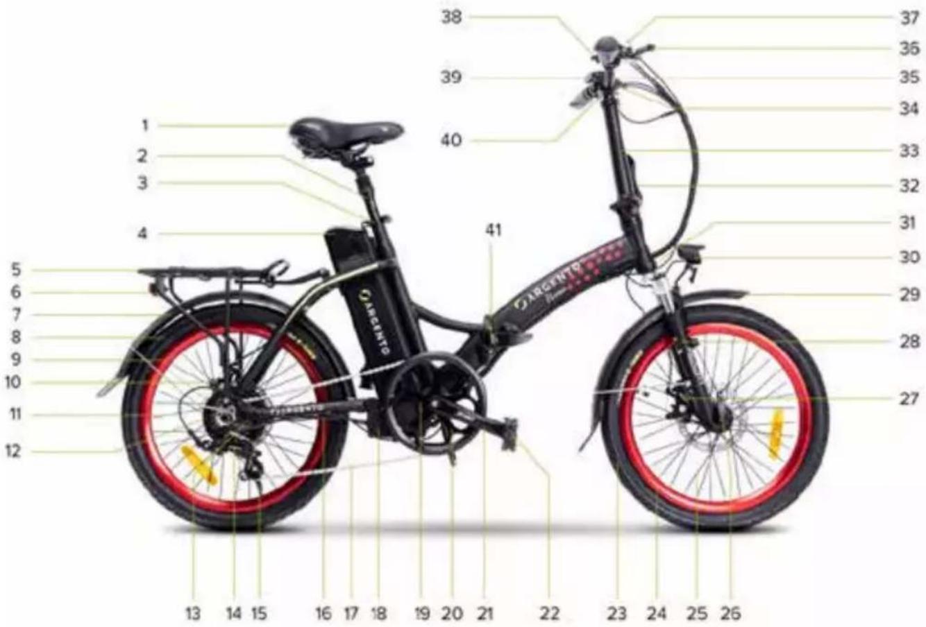
- Saddle
- Folding seat post
- Seat post clamp
- Li-Ion battery
- Rear luggage rack
- Rear LED light
- Rear mudguard
- Rear tyre
- Front wheel rim
- Rear disc brake
- Rear wheel
- Motor
- 7-Speed cassette
- Rear gear change - derailleur
- Stand (opposite side)
- Motor port
- Chain
- Control unit compartment
- PAS
- Chainring
- Crank arm (right side)
Example image of bike structure and components.
- Folding pedal (right side)
- Front tyre
- Front wheel rim
- Front wheel
- Quick-release front wheel
- Front disc brake
- Suspension fork
- Front mudguard
- Front LED light
- Frame serial number
- Handlebar stem lock/unlock lever
- Telescopic and folding handlebar stem
- Handlebar attachment
- Handlebars
- Rear wheel brake lever (right side)
- Gear change - indexed control
- Bell
- Display
- Front wheel brake lever (left side)
- Frame opening/closing mechanism
4. Technical data sheet
| Product description Product code | EAN code | |
| Argento E-Bike Piuma Silver AR-BI-220003 8052679455980 | ||
| Argento E-Bike Piuma Blue AR-BI-220004 8052679455997 | ||
| General information | ||
| Display LED - CDE9-BT | ||
| Motor Bafang 36V 250W brushless - rear | ||
| Battery Li-Ion 36V 10.4Ah 374Wh - external and removable | ||
| Brakes with front and rear disc mechanism - brake lever with cut-of sensor | ||
| Gear change Shimano 7 gears (1x7) - rear derailleur | ||
| Drive chain - 7 speed | ||
| Wheels 20" front and rear | ||
| Lights Front and rear LEDs | ||
| Frame aluminium 6061 - folding | ||
| Battery charger Input: AC 100V-240V 1.8A (Max) - Output: DC 42V 2.0A (Max) | ||
| Maximum load supported by E-bike | 100 kg | |
| Maximum load supported by luggage rack | 25 kg | |
| Weight of E-bike 23 kg~ | ||
| Full speed | 25km/h | |
| Product description Product code | EAN code | |
| Argento E-Bike Piuma Silver AR-BI-210002 | 8052 | 870486615 |
| Argento E-Bike Piuma Blue AR-BI-210001 | 8052 | 870486608 |
| General information | ||
| Display LED - CDE9-BT | ||
| Motor Xofo 36V 250W brushless - rear | ||
| Battery Li-Ion 36V 10.4Ah 374Wh - external and removable | ||
| Brakes with front and rear disc mechanism - brake lever with cut-of sensor | ||
| Gear change Shimano 7 gears (1x7) - rear derailleur | ||
| Drive chain - 7 speed | ||
| Wheels 20" front and rear | ||
| Lights Front and rear LEDs | ||
| Frame aluminium 6061 - folding | ||
| Battery charger Input: AC 100V-240V 1.8A (Max) - Output: DC 42V 2.0A (Max) | ||
| Maximum load supported by E-bike | 100 kg | |
| Maximum load supported by luggage rack | 25 kg | |
| Weight of E-bike 23 kg~ | ||
| Full speed | 25km/h | |
| Argento E-Bike Piuma+ Red AR-B | -210021 8052870486813 | |
| Argento E-Bike Piuma+ Blue AR-B | -210022 8052870486820 | |
| General information | ||
| Display LED - King-Meter 790 | ||
| Motor Xofo 36V 250W brushless - | rear | |
| Battery Li-Ion 36V 10.4Ah 374Wh - | external and removable | |
| Brakes with front and rear mechanical disk brake - brake lever with cut-of sensor | ||
| Gear change Shimano 7 gears (1x7) - rear derailleur | ||
| Drive chain - 7 speed | ||
| Wheels 20" front and rear | ||
| Lights Front and rear LEDs | ||
| Frame aluminium 6061 - folding | ||
| Battery charger | Input: AC 100V-240V 1.8A (Max) - Output: DC 42V 2.0A (Max) | |
| Maximum load supported by E-bike | 100 kg | |
| Maximum load supported by luggage rack | 25 kg | |
| Weight of E-bike | 23 kg~ | |
| Full speed | 25km/h | |
| Product description Product code | EAN code | |
| Argento E-Bike Piuma-S | AR-BI-220005 | 8052679456000 |
| AR-BI-210003 8052870486622 | ||
| General information | ||
| Display LCD - CDC13-BT | ||
| Motor Bafang 36V 250W brushless - rear | ||
| Battery Li-Ion 36V 10.4Ah 374Wh - external and removable | ||
| Brakes with front and rear mechanical disk brake - brake lever with cut-of sensor | ||
| Gear change Shimano 7 gears (1x7) - rear derailleur | ||
| Drive chain - 7 speed | ||
| Wheels 20" front and rear | ||
| Lights Front and rear LEDs | ||
| Frame aluminium 6061 - folding | ||
| Battery charger | Input: AC 100V-240V 1.8A (Max) - Output: DC 42V 2.0A (Max) | |
| Maximum load supported by E-bike | 100 kg | |
| Maximum load supported by luggage rack | 25 kg | |
| Weight of E-bike | 23 kg ^ | |
| Full speed | 25km/h | |
| Argento E-Bike Piuma-S + Yellow | AR-BI-210023 8052870486837 | |
| General information | ||
| Display LCD - APT 500S | ||
| Motor Bafang 36V 250W brushless - rear | ||
| Battery Li-Ion 36V 10.4Ah 374Wh - external and removable | ||
| Brakes with front and rear mechanical disk brake - brake lever with cut-of sensor | ||
| Gear change Shimano 7 gears (1x7) - rear derailleur | ||
| Drive chain - 7 speed | ||
| Wheels 20" front and rear | ||
| Lights Front and rear LEDs | ||
| Frame aluminium 6061 - folding | ||
| Battery charger Input: AC 100V-240V 1.8A (Max) - Output: DC 42V 2.0A (Max) | ||
| Maximum load supported by E-bike | 100 kg | |
| Maximum load supported by luggage rack | 25 kg | |
| Weight of E-bike 23 kg~ | ||
| Full speed | 25km/h | |
5. Assembly
Carefully remove the bike from the packaging* and remove the protective material taking care not to damage the relevant aesthetic parts or force the cables and pre-assembled components.
*The bike must be removed from the packaging by two adults to ensure that it is not damaged and avoid the risk of injury and/or crushing.
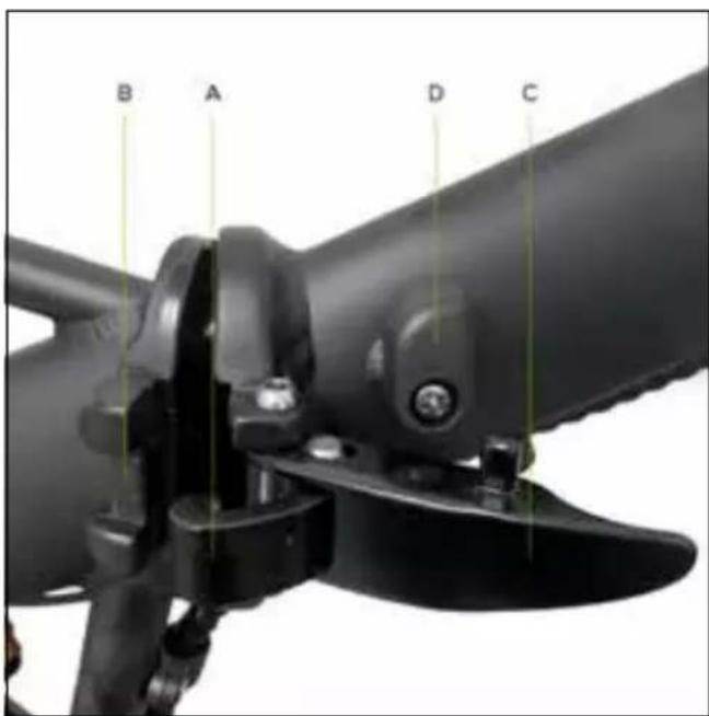
After aligning the front of the frame with the rear part by rotating them around the coupling hinge pin, tighten the lever on the frame opening/closing mechanism as follows:
insert the securing bracket (A) of the opening/closing mechanism lever into its housing (B) on the rear part of the frame.
Push the lever (C) towards the front of the frame, ensuring that it is secured using the locking device (D).
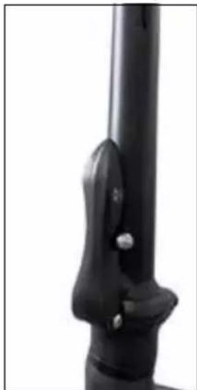
Positioning the handlebar stem
Raise the handlebar stem until it is vertical; tighten the handlebar stem using the locking device indicated by the letter A.
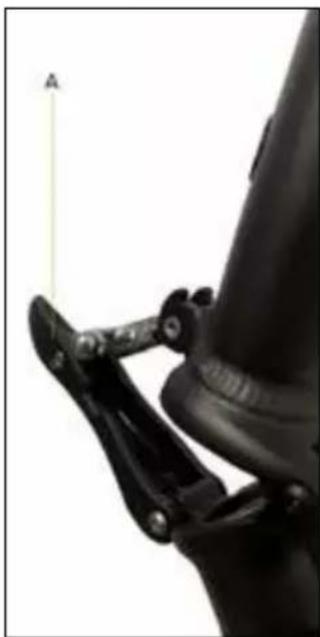
natural_image
Close-up of a mechanical linkage mechanism with a labeled point A (no text or symbols on the diagram itself)
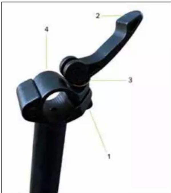
natural_image
Close-up of a black mechanical lever with a labeled point A (no text or symbols on the lever itself)Positioning the handlebars
Position the handlebars on the handlebar attachment taking care to centre and adjust them correctly so they slot onto the controls, tightening the handlebar attachment lever (tightening device between the handlebars and handlebar attachment).
Handlebar stem plate assembly/disassembly instructions for handlebar installation/removal (if necessary - optional)
Remove the handlebar stem from the top end of the handlebar attachment as follows:
remove the screw 1 and then, the lever 2.
Then, remove the metal plate 3 and lastly, remove the metal plate 4 by sliding it sideways.
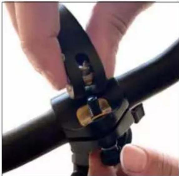
natural_image
Close-up of hands using a black metal tool to adjust or install a pipe fitting (no text or symbols visible)Now put the previously removed handlebar stem back in place, following the steps in reverse order.
Make sure to tighten properly to avoid dangerous situations while riding.
Installing and positioning the seat post
Insert the seat post into the seat tube of the frame and, after positioning the saddle correctly, secure the seat post firmly using the special clamping device (seat post clamp) on the frame.
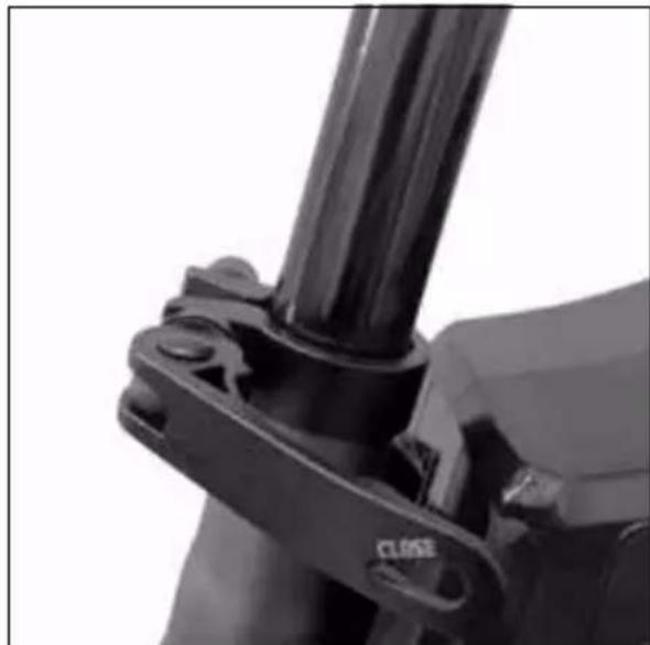
natural_image
Close-up of a mechanical clamp or bracket with a black cylindrical component and a 'CLOSE' label (no readable text beyond the label)
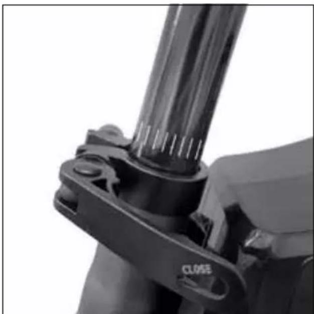
Minimum insertion seat post insertion limit
For structural and safety reasons, it is strictly forbidden, when using the bike, to extract the seat post from the seat tube of the frame beyond the limit indicated on the latter to avoid the risk of causing any structural fractures to the bike and incurring serious injuries.
The seat post is deemed to be correctly and safely positioned inside the seat tube of the frame by inserting it so that no markings and/or graphic indication of the minimum insertion limit can be seen; see:
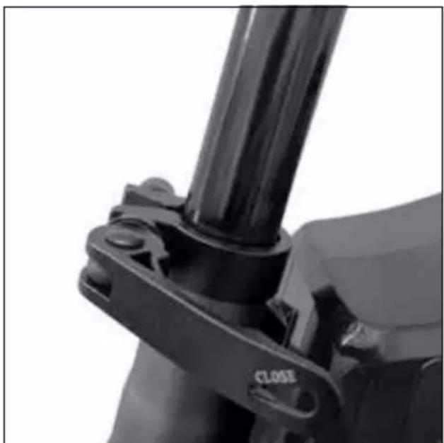
natural_image
Close-up of a mechanical clamp or bracket component with no visible text or symbolsCorrect position Incorrect position
natural_image
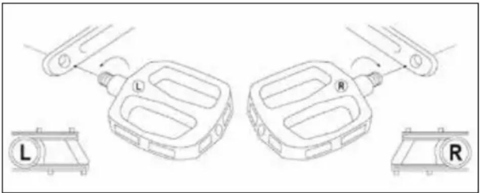
Close-up of a mechanical clamp or bracket component with no visible text or symbolsInstalling the pedals
Locate the right pedal (marked with the letter R) and left pedal (marked with the letter L).
Fit the right pedal (R) by inserting the threaded pin of the pedal into the corresponding crank arm on the right side of the bike and screwing it clockwise (turn it towards the front wheel) until it is tightened using a 15mm wrench.
Fit the left pedal (L) by inserting the threaded pin of the pedal into the corresponding crank arm on the left side of the bike and screwing it anticlockwise (turn it towards the front wheel) until it is tightened using a 15mm wrench.
natural_image
Technical line drawing of a mechanical component with labeled parts (L, R) and directional arrows indicating motion or assembly (no text or symbols beyond labels)! CAUTION
Verify and regularly check that the various bolted elements, fastening screws, quick releases and pass-through pins are correctly tightened, and perform an overall check to ensure that all the parts are in order.
The nuts and all the other self-tightening parts can become loose so, these components need to be periodically checked and tightened.
The recommended tightening torques for fastening the specific parts/components on the bike (e.g. handlebars, handlebar attachment and stem, saddle, saddle clamp, wheels, etc.) can be identified depending on the relevant elements. An average torque of 20Nm can be used for all other fastenings.
In the absence of precise technical indications, you can check if the parts/components fastened by lever systems (quick release, handlebar stem, seat clamp, etc.), are correctly tightened by checking that the part in question/component being fastened does not move and/or is not unstable if you attempt to remove and/or detach it (handlebar, seat post, wheels, etc.). The tightening lever should be resistant when it is closed (i.e. it leaves a mark on the palm of the hand used to tighten the lever, the so-called “imprint on palm”). It should also require a considerable force to be exerted to open it again after it has been closed.
Rear light
The rear LED light is already installed on the end of the rear luggage rack.
It can be switched on and of manually using the button on the light itself or, at the same time as the front LED light is switched ON/OFF via the control on the display, if this option is included.

Battery key set
The electrically power assisted cycle is supplied with 2 keys uniquely associated with the key lock on the battery installed on the bike to allow it to be released and removed and, if applicable, to be enabled.
Identify the keys on the bike, located near the handlebar or attached to another component of the electrically power assisted cycle (frame or battery), taking care that they do not get mislaid.
Check with negative outcome
If, during assembly, you encounter any manufacturing defects, unclear steps or difficulties with assembly, do not ride the electrically power assisted cycle and contact the after-sales service of your authorised dealer or visit the website www.argentobike.it
In the interest of technological development, the manufacturer reserves the right to modify the item with no prior notice and this manual will not be automatically updated.
For further information and to consult any new versions of the manual, please visit www.argentobike.it
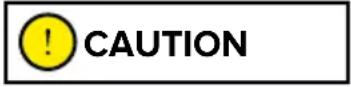
Folding the electrically power assisted cycle
Fold the pedals by operating the release mechanism.
natural_image
Close-up of a hand holding a black mechanical component with a yellow arrow indicating a force or movement (no text or symbols visible)Pedal open
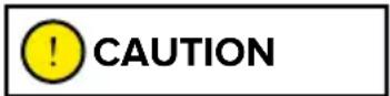
natural_image
Close-up of a black bicycle brake mechanism with visible tracks and brackets (no text or symbols)Pedal closed
Release the handlebar stem closing mechanism by opening the locking device.
natural_image
Close-up of a black mechanical lever handle with a small metallic knob (no text or symbols visible)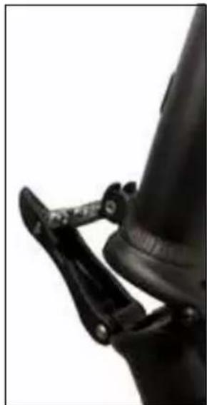
natural_image
Close-up of a black mechanical clamp securing a cylindrical object (no visible text or symbols)Fold the handlebar stem downwards.
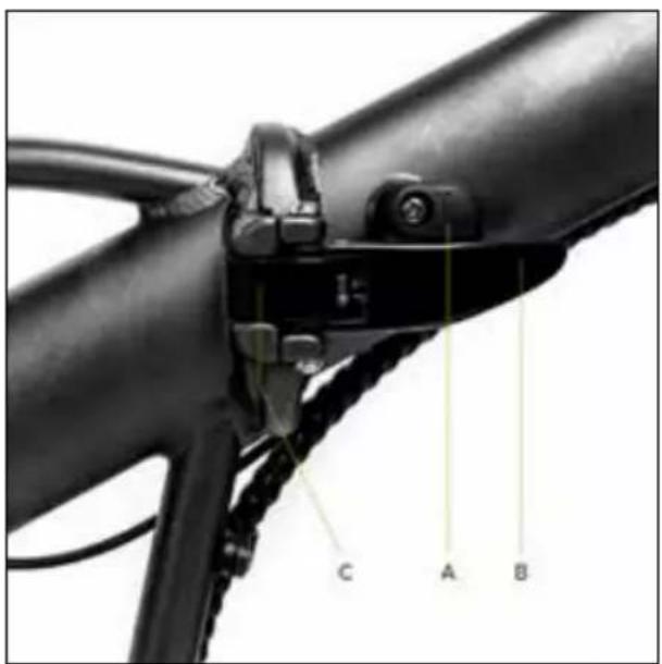
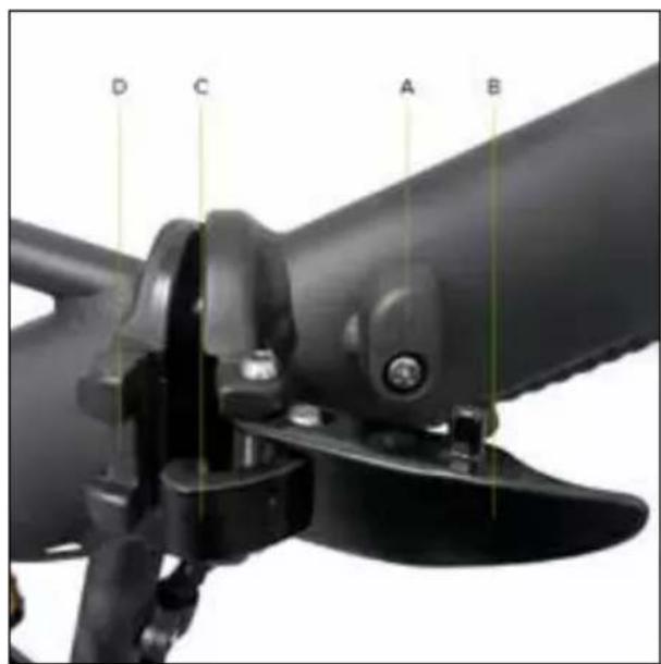
Turn the lever locking device (A) in the frame opening/closing mechanism in an anticlockwise direction. Pull the lever (B) outwards until the locking hook (C) can be extracted from its seat (D).
natural_image
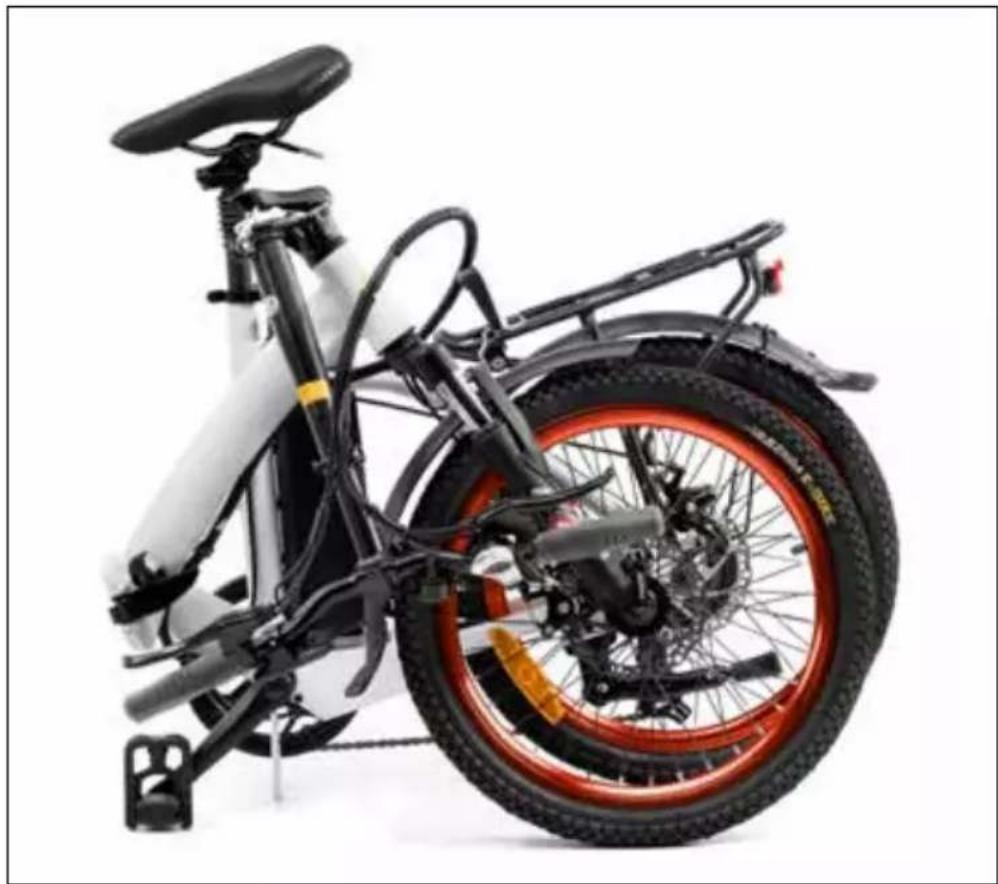
Side view of a white and black electric scooter with red and orange racing wheel (no visible text or symbols)Fold the entire frame of the electrically power assisted cycle.
To open the bike frame, carry out the sequence in reverse.
6. Display
The electrically power assisted cycle has a control device on the handlebar, LED or LCD display, powered by the battery supplied with the bike which controls all the bike's electrical and electronic functions.
• LED display - CDE9-BT
Overview of controls and symbols
- ON/OFF button
- Light ON/OFF button
- Button to increase assisted pedalling (+)
- Button to decrease assisted pedalling (-)
- LED indicator to signal assisted pedalling selected (1-5)
- LED indicator for residual battery charge (1-5)
- Walk assist mode ON/OFF lever
Function description
Display ON/OFF
Press the ON/OFF button for at least 1 second to switch the display on or of.
Selecting the assisted pedalling level
Press the relevant button to increase or decrease the level of selected assisted pedalling.
The assisted pedalling level selected, which can vary from 1 to 5, is indicated on the display by the corresponding number of LED indicator lights; see: 1-2-3-4-5.
The assisted pedalling level highlighted by 1 LED light on the display indicates the minimum setting for electrical support provided by the motor.
The assisted pedalling level highlighted by 5 LED lights on the display indicates the maximum setting for electrical assistance provided by the motor.
Electric assistance from the motor is excluded by decreasing the selected assisted pedalling level until the relevant LED lights disappear completely.
Enabling walk assist mode
Decrease the selected assisted pedalling level until the relevant LED lights disappear completely and press the lever to enable the walk assist mode which allows you to activate electric motor assistance up to a speed of 6Km/h.
Disable the function by releasing the lever.

The walk assist mode must be used in compliance with the regulations in force in the country of use and is only allowed when pushing the electrically power assisted cycle by walking alongside the bicycle and holding the handlebar grips firmly with both hands.
It is strictly prohibited to enable the walk assist mode when you are sitting on the saddle of the electrically power assisted cycle to avoid the danger of injury and the risk of damaging the electrical components of the bike.
Switching the lights ON/OFF
Press the relevant button for at least 1 second to switch the front light on or of (and rear light, if applicable).
Residual battery charge indicator
The battery charging level is shown on the display by the number of LED lights that are highlighted; see: 0-1-2-3-4-5.
If 5 LED lights are highlighted at the same time, it means that the battery is charged to the maximum percentage set and detected at the time.
The reduction in the number of LED lights simultaneously highlighted indicates that the available battery charge and consequent autonomy is decreasing.
The level of the battery charging indicator may fluctuate depending on how the electrically power assisted cycle is being used, for example, when going up a slope, the level displayed can drop rapidly as there is a much higher battery consumption.
The individual indicator lights give an indication of the specific battery charge range detected at the time and do not necessarily represent a percentage of the residual autonomy.
Malfunction indicator light
If a malfunction of the electrical and/or electronic system of the bike is detected, all the LED lights on the display will light up and flash.
Turn of the display and then, turn it on again, identify the malfunction corresponding to the number of flashes highlighted (flash); a table with explanations is shown below:

CAUTION
| Number of flashes | Malfunction description |
| 2 Malfunction when using the walk assist mode lever | |
| 3 Brake sensor malfunction | |
| 4 Control unit malfunction | |
| 7 Control unit overheated | |
| 8 High voltage protection (voltage above threshold) | |
| 10 Motor malfunction (excessive power consumption) | |
| 11 Motor hall sensor malfunction | |
| 17 Display-control unit wiring communication malfunction | |
| 18 Display-control unit programming communication malfunction | |
| 19 Brake sensor malfunction | |
| 20 Motor block | |
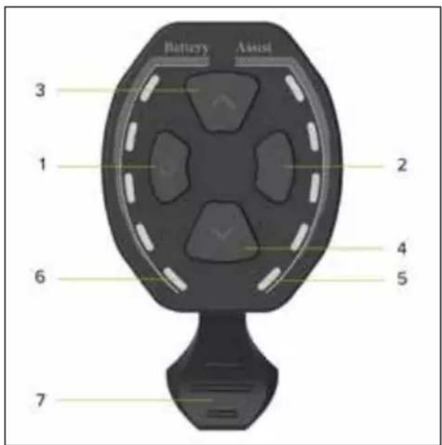
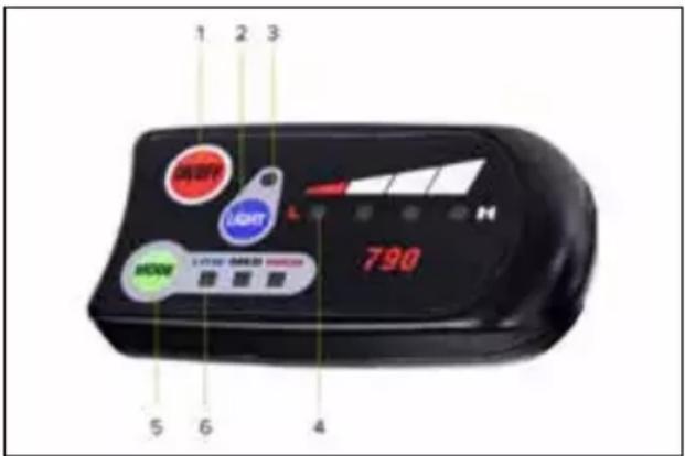
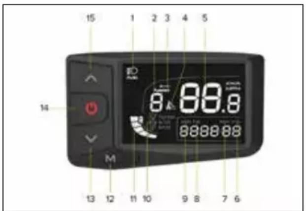
• LED display - King-Meter 790
Overview of controls and symbols
- ON/OFF: display ON/OFF button
- LIGHT: lights ON/OFF button
- LED indicator light for lights ON/OFF
- LED indicator light for residual battery charge
- MODE: assisted pedalling level selection button
- LED indicator to signal assisted pedalling selected (LOW-MED-HIGH)
Function description
Display ON/OFF
Press the ON/OFF button for at least 1 second to switch the display on or of.
Selecting the assisted pedalling level
Press the MODE button to set the level of assisted pedalling selected.
The sequence of levels that can be selected is the following: LOW-MED-HIGH.
The LED indicator light highlighted at the selected level will set the corresponding level of electrical assistance provided by the motor.
HIGH allows the motor to provide the maximum level of assisted pedalling that can be delivered; LOW and MED provide lower assisted pedalling levels.
Switching the lights ON/OFF
Press the LIGHT button for at least 1 second to switch the front light and rear light (if applicable) on or of.
Residual battery charge indicator
The battery charge level is shown on the display within the reference values L (Low) and H (High) by a number of LED lights between 0 and 4.
If 4 LED lights are highlighted at the same time, it means that the battery is charged to the maximum percentage set and detected at the time.
The reduction in the number of LED lights simultaneously highlighted indicates that the available battery charge and consequent autonomy is decreasing.
The level of the battery charging indicator may fluctuate depending on how the electrically power assisted cycle is being used, for example, when going up a slope, the level displayed can drop rapidly as there is a much higher battery consumption.
The individual indicator lights give an indication of the specific battery charge range detected at the time and do not necessarily represent a percentage of the residual autonomy.
• LCD display - CDC13-BT
Overview of controls and symbols
- Indicator light for light ON
- Assist: indicator of the assisted pedalling level selected (number)
- Error: malfunction warning light
- Indicator light for walk assist mode ON
- Digital speedometer: indicator light for speed detected during use (Km/H or MPH)
- AVG: display of average speed data recorded during last use (Km/h or MPH)
- MAX: display of maximum speed data recorded during the last use (Km/h or MPH)
- TRIP: display of partial distance travelled (Km or Miles)
- ODO: display of total distance travelled (Km or Miles)
- Travel mode corresponding to the selected assisted pedalling level (ECO-STD-Turbo)
- Indicator light for residual battery charge
- M: mode button (MODE)
- Button to vary and/or decrease value (-)
- ON/OFF button
- Button to vary and/or increase value (+)
Function description
Display ON/OFF
Press the ON/OFF button for at least 3 seconds to switch the display on or of.
Selecting the assisted pedalling level
Press the relevant button to increase or decrease the level of selected assisted pedalling.
There are between 1 and 5 assisted pedalling levels that can be selected (Assist).
Assist level 1 sets minimum electrical support by the motor (minimum power - ECO mode).
Assist levels 2 and 3 set intermediate electrical support by the motor (minimum power - STD mode).
Assist levels 4 and 5 set maximum electrical support by the motor (maximum power - Turbo mode).
If you select level 0, you exclude electrical assistance from the motor.
Enabling walk assist mode
Set the walk assist level to 0 and then, press and hold the - button to enable the walk assist mode which allows you to activate electric motor assistance up to a maximum speed of 6 Km/h.
Disable the function by releasing the button.
The walk assist mode must be used in compliance with the regulations in force in the country of use and is only allowed when pushing the electrically power assisted cycle by walking alongside the bicycle and holding the handlebar grips firmly with both hands.
It is strictly prohibited to enable the walk assist mode when you are sitting on the saddle of the electrically power assisted cycle to avoid the danger of injury and the risk of damaging the electrical components of the bike.
Switching the light ON/OFF
Press the ON/OFF button quickly to turn the front light (and rear light, if applicable) on and of.
Viewing data (AVG - MAX - TRIP - ODO)
The data available on speed (AVG and MAX) and distance (TRIP and ODO) will be displayed alternately and automatically in sequence: AVG - MAX - TRIP - ODO.
The partial usage data (TRIP - AVG - MAX) will automatically reset after the display is turned of.
Indicator light for residual battery charge
The battery charge level is shown on the display screen as a number of dashes between 0 and 5.
If there are 5 dashes, it means that the battery is charged to the maximum percentage defined and detected instantly.
Less dashes are shown to indicate a decrease in the battery charge level available and subsequent autonomy.
The level of the battery charging indicator may fluctuate depending on how the electrically power assisted cycle is being used, for example, when going up a slope, the level displayed can drop rapidly as there is a much higher battery consumption.
The individual dashes indicate the specific battery charge range detected at the time and do not necessarily indicated a percentage of the residual autonomy.
Malfunction indicator light
If a malfunction of the bike's electrical and/or electronic system is detected, the relevant warning light will appear on the display screen and the relevant identification Error Code will be displayed at the same time.
| Error Code Malfunction description | |
| 2 Malfunction when using the walk assist mode lever | |
| 3 Brake sensor malfunction | |
| 4 Control unit malfunction | |
| 7 Control unit overheated | |
| 8 High voltage protection (voltage above threshold) | |
| 10 Motor malfunction (excessive power consumption) | |
| 11 Motor hall sensor malfunction | |
| 17 Display-control unit wiring communication malfunction | |
| 18 Display-control unit programming communication malfunction | |
| 19 Brake sensor malfunction | |
| 20 Motor block |
Parameter configuration
Press the M button for at least 3 seconds to access the configuration menu and then, quickly press the M button to confirm the data entered and display the next parameter to be configured.
Select the value for the individual parameter by pressing the + or - buttons and confirming it by pressing the M button (quickly to access the next parameter).
The sequence of parameters that can be configured is shown below:
P1 - Unit of measurement:
press the + or - buttons to select the unit of measurement for the speed and distance data shown on the display:
international metric system (Km/h and Km) or British imperial system (MPH and Miles)
P2 - User password ON/OFF display:
available options = on / of
of = selecting "of", confirmed by pressing the M button, excludes the user password request (identification code) to allow the user to access and activate the display and allow full control of all the functions provided for the electrically power assisted cycle.
The display controls and functions will be immediately accessible after pressing the ON button.
ON = selecting "on", confirmed by pressing the M button, enables the configuration parameter which activates the display and access to all the functions included for full control of the electrically power assisted cycle only after entering a user password (identification code).
Display controls and functions, after pressing the ON button, will only be accessible after entering the user password previously set (P3).
P3 - User password:
Parameter only displayed after the “ON” option has been selected which allows the user to enable the display access configuration exclusively by entering the password (numeric identification code consisting of 4 digits) previously set and confirmed as follows:
- select the 4 digits which make up the password by pressing the + and - buttons and confirming them individually by pressing the ON/OFF button
- confirm the numeric identification code consisting of 4 numbers by pressing the M button.
0000 - System parameter setting password:
if incorrect data on the speed (Km/h and Km) and distance (MPH and Mile) are shown on the display, contact the after-sales technical support service for assistance:
Overview of controls and symbols
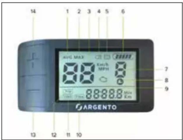
- AVG: display of average speed data recorded during last use (Km/h or MPH)
- MAX: display of maximum speed data recorded during the last use (Km/h or MPH)
- Digital speedometer: indicator light for speed detected during use (Km/H or MPH)
- Indicator light for lights ON
- Indicator light for instant motor deactivation by brake lever operation with cut-of sensor supplied (if included)
- Indicator light for residual battery charge
- Indicator light for the assisted pedalling level selected (number) or indicator light for walk assist mode ON (P)
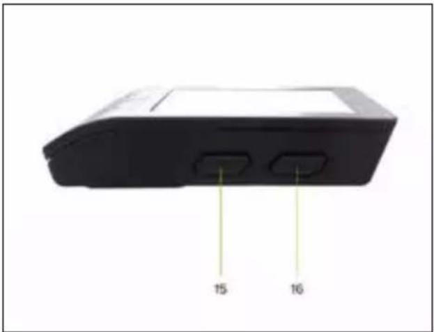
natural_image
Back view of a black electronic device with two labeled ports (15 and 16), no visible text or symbols beyond labels.- Indicator light for walk assist mode ON corresponding to a value of 1 or above
- Malfunction warning light
- Time: display of overall usage time (Hours:Minutes)
- ODO: display of total distance travelled (Km or Miles)
- TRIP: display of partial distance travelled (Km or Miles)
- Button to vary and/or decrease value (-)
- Button to vary and/or increase value (+)
- M: mode button (MODE)
- ON/OFF button
Function description
Display ON/OFF
Press the ON/OFF button for at least 1 second to switch the display on or of.
Selecting the assisted pedalling level
Press + or - button to increase or decrease the level of selected assisted pedalling.
The display is pre-configured to offer the user 5 different assisted pedalling levels (variable values from 1 to 5).
Assistance level 1 provides minimum electrical assistance from the motor.
Assistance level 5 provides maximum electrical support from the motor.
If you select level 0, you exclude electrical assistance from the motor.
When configuring the display, you can modify the parameter for the interval of assisted pedalling that can be selected: 0-3, 0-5 and 0-9.
These options do not change the minimum and maximum value of electrical assistance provided by the motor, but only allow a different distribution of the pedalling assistance levels between the minimum and maximum value as described in the table below:
| Number of assisted pedalling levels | ||
| 3 (1-3) 5 (1-5) 9 (1-9) | ||
| -11 | ||
| --2 | ||
| 123 | ||
| --4 | ||
| -35 | ||
| 2-6 | ||
| -47 | ||
| --8 | ||
| 359 | ||
Enabling walk assist mode
Select a walk assist level equal to or greater than 1 and then, press and hold the - button to enable the walk assist mode which allows you to activate electric motor assistance up to a speed of 6Km/h.
Disable the function by releasing the - button.
The walk assist mode must be used in compliance with the regulations in force in the country of use and is only allowed when pushing the electrically power assisted cycle and walking alongside it holding the handlebar grips firmly with both hands.
It is strictly prohibited to enable the walk assist mode when you are sitting on the saddle of the electrically power assisted cycle to avoid the danger of injury and the risk of damaging the electrical components of the bike.
Switching the lights ON/OFF
Press the + button for at least 1 second to light up the display screen and switch the front light and rear light (if applicable) on or of.
Viewing data (AVG - MAX - TRIP - ODO - Time)
Press the M button quickly to view the successive usage data available for the speed (AVG and MAX), distance travelled (TRIP and ODO) and duration (Time).
AVG - MAX: the data is temporarily displayed in line with the digital speedometer followed by automatic reset of the data for the instant speed.
TRIP - ODO - Time: the selected data remains permanently displayed until the display is turned of.
Press the + and - buttons at the same time for 1 second to reset the AVG, MAX, TRIP and TIME data.
Indicator light for residual battery charge
The battery charge level is shown on the display screen as a number of dashes between 0 and 5.
If there are 5 dashes, it means that the battery is charged to the maximum percentage defined and detected instantly.
Less dashes are shown to indicate a decrease in the battery charge level available and subsequent autonomy.
The level of the battery charging indicator may fluctuate depending on how the electrically power assisted cycle is being used, for example, when going up a slope, the level displayed can drop rapidly as there is a much higher battery consumption.
The individual dashes indicate the specific battery charge range detected at the time and do not necessarily indicated a percentage of the residual autonomy.
Malfunction indicator light
If a malfunction of the bike's electrical and/or electronic system is detected, the relevant warning light will appear on the display screen and the corresponding identification Error Code will be displayed at the same time.
| Error Code Malfunction description | |
| 04 Accelerator malfunction | |
| 06 Low voltage protection (voltage below threshold) | |
| 07 High voltage protection (voltage above threshold) | |
| 08 Motor hall sensor malfunction | |
| 09 Motor phase line malfunction | |
| 10 Control unit overheated | |
| 11 Motor over temperature | |
| 12 Current sensor malfunction | |
| 13 Battery over temperature | |
| 14 Motor malfunction | |
| 21 Speed sensor malfunction | |
| 22 BMS malfunction | |
| 30 Communication malfunction |
Parameter configuration
Press the M button for at least 2 seconds to access the configuration menu and then, quickly press the M button to confirm the data entered and display the next parameter to be configured.
Select the desired value for the individual parameter by pressing the + or - buttons and confirm it by pressing the M button (quickly to access the next parameter or for at least 2 seconds to exit the configuration menu).
The sequence of parameters that can be configured is shown below:
S7 - Unit of measurement:
press the + or - buttons to select the unit of measurement for the speed and distance data shown on the display:
international metric system (Km/h and Km) or British imperial system (MPH and Miles)
B1 - Back lighting:
press the + or - buttons to change the brightness level of the display screen (from 1 to 5).
of - Automatic switch of:
press the + or - buttons to set the minutes before the automatic switch-of of the display (from 1 to 15).
The function can be disabled by selecting 0.
Hd - System parameter:
Pre-defined value = 20
If faulty data for speed and distance are shown on the display, reset the correct value indicated by using the + or - buttons.
Pd - Password:
enter the password "1919" using the + or - buttons and confirming each single digit by pressing the M button to configure the additional usage parameters.
SL - Speed limiter:
press the + or - buttons to increase or decrease the set speed limit (from 10 to 100).
In compliance with the requirements of European Directive 2002/24/EC, the pedal assistance provided by the electric motor supplied with the product will automatically be cut of when a speed of 25 km/h is reached, even a higher value has been set.
HL - System parameter:
Pre-defined value = 6
If faulty data for speed and distance are shown on the display, reset the correct value indicated by using the + or - buttons.
PA - Number of pedal assistance levels available:
press the + or - buttons to set the number of pedal assistance levels that can be selected while using the bike.
Values available:
UbE = test value, do not set
0-3 = 3 pedal assistance levels available (from 1 to 3)
0-5 = 5 pedal assistance levels available (from 1 to 5)
0-9 = 9 pedal assistance levels available (from 1 to 9)
7. Battery
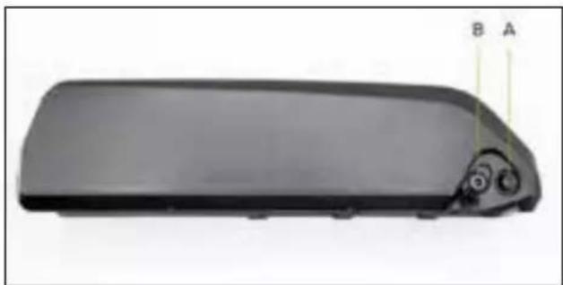
The electrically power assisted cycle starts and powers its electrical and electronic functions after the external and removable lithium-ion battery is turned on using either a key or switch, depending on the version supplied with the bike, and is correctly charged and installed.
Li-Ion battery - Version with switch
natural_image
Exterior view of a black rectangular electronic device with a small circular component and labeled points A and B (no text or symbols on the device itself)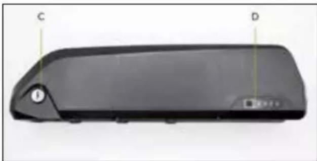
natural_image
Black rectangular device rear cover with labeled points C and D, showing no visible text or symbols beyond labelsA. Battery ON/OFF switch (I=On / O=of)
B. Charging port for battery charger
C. Battery lock/unlock mechanism
D. Residual battery charge indicator
Li-Ion battery - Version with key
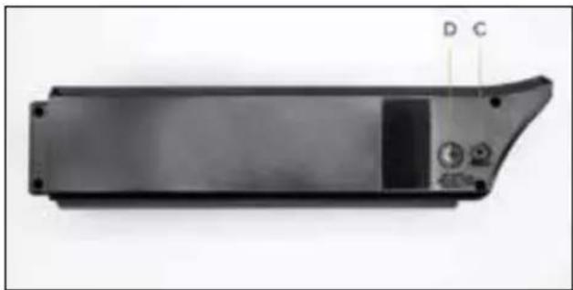
natural_image
Exterior view of a black rectangular electronic device casing with labeled ports (D, C) and control buttons (no readable text beyond labels)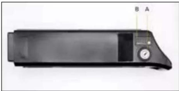
natural_image
Black rectangular electronic device with a control panel and labeled points A and B (no visible text or symbols on the device itself)A. Battery ON/OFF/lock/unlock mechanism
B. Residual battery charge indicator
C. Charging port for battery charger
D. USB port for portable charging device
Battery removal and insertion
The battery can be removed from the bike to prevent theft, to recharge it or store it in ideal conditions.
Li-Ion battery - version with switch
Removing the battery:
Disable the battery via the specific switch and insert the key supplied in the lock on the battery. Turn the key in a counter-clockwise direction until the release position. Remove the battery from its slot on the frame stem tube sliding it upwards and outwards until it has been completely removed.
Inserting the battery:
Insert the key supplied in the lock on the battery. Turn the key in a counter-clockwise direction until the release position. Insert the battery in its slot on the frame stem tube and complete the installation by turning the key clockwise until it is locked.
Check that the battery is correctly installed and secured by trying to pull it out and/or making sure that it is securely fastened to the frame and does not move.
Li-Ion battery - version with key
Removing the battery:
Insert the key supplied in the lock on the battery. Turn the key in a counter-clockwise direction until the release position. After folding the saddle and/or checking that its position does not obstruct the removal of the battery, grab the handle on the battery and pull it out from its housing fixed to the frame, by pulling upwards.
Inserting the battery:
Insert the key supplied in the lock on the battery. Turn the key in a counter-clockwise direction until the release position. After folding the saddle and/or checking that its position does not obstruct the insertion of the battery, grab the handle on the battery and insert it into its slot fixed to the frame, pushing downwards until it stops. Turn the key in a clockwise direction to the of position to ensure the battery is secured to the frame.
Check that the battery is correctly installed and secured by trying to pull it out and/or making sure that it is securely fastened to the frame and does not move.
Battery charging
Before using the electrically power assisted cycle for the first time, the battery must be fully charged using the battery charger supplied.
The average time battery charging time is between approximately 4 and 6 hours, depending on the residual charge of the battery.
We recommend charging the battery with the specific battery charger after each use of the electrically power assisted cycle.
Only use the battery charger provided or an approved model with the same technical specifications, taking care to observe the same methods and precautions of use indicated on the charged or in the manual.
| EPAC Battery charger INPUT Battery charger OUTPUT | |
| Piuma AC 100V-240V 1.8A (Max) DC 42V 2.0A (Max) | |
| Piuma + AC 100V-240V 1.8A (Max) DC 42V 2.0A (Max) | |
| Piuma-S AC 100V-240V 1.8A (Max) DC 42V 2.0A (Max) | |
| Piuma-S + AC 100V-240V 1.8A (Max) DC 42V 2.0A (Max) | |
Make sure that the electrically power assisted cycle is switched of and the battery is switched of/disabled (if required by the model of battery supplied with the bike).
Make sure that the battery charger, its jack and the charging port of the battery are dry.
Connect the battery charger jack to the battery charging port and then, the mains power socket (230V/50Hz).
There is a red indicator light when the battery is charging. When the indicator light turns green, it signals that the battery charging cycle has been completed.
Disconnect the battery charger jack from the battery charging port and then, the mains power socket.
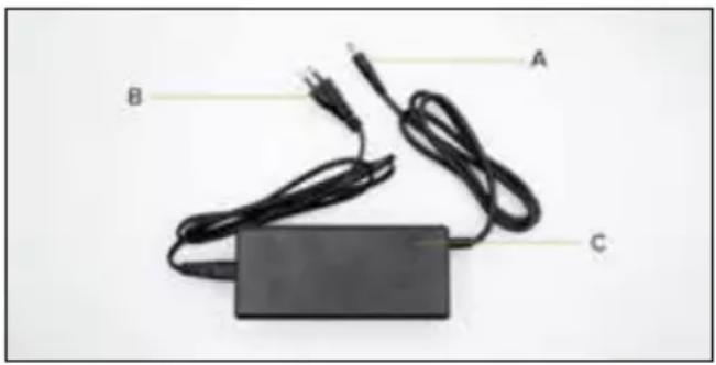
natural_image
Black electronic device with two cables and a rectangular base, labeled A, B, C (no text or symbols on the device itself)A. Battery charging jack
B. Power supply jack
C. Battery charging LED indicator light
Using a battery charger that differs from the one supplied, which is not suitable or approved, to charge the e-bike battery may damage it or involve other potential risks.
Never leave the e-bike unsupervised while it is charging.
Do not switch on or ride the e-bike during charging.
Keep out of the reach of children during charging. Do not place anything on top of the battery charger during use; do not allow any liquid or metal to get inside the battery charger.
The battery charger heats up during the battery charging cycle.
Do not charge the battery immediately after use. Allow the battery to cool down before charging it.
The item should not be charging for extended periods. Overcharging reduces battery life and poses additional potential hazards.
Do not allow the battery to completely discharge to avoid damaging it and causing it to lose efficiency.
Damage caused by the battery being left uncharged for a long period is irreversible and is not covered by the limited warranty. Once the damage has occurred, the battery cannot be recharged (the battery must not be dismantled by unqualified personnel, as this could lead to electric shocks, short circuits or even major safety incidents).
Charge the battery at regular intervals (at least once every 3-4 weeks), even if the electrically power assisted cycle has not been used for an extended period.
Charge the battery in a dry environment, away from flammable materials (e.g. materials that may burst into flame), preferably at an indoor temperature of 15-25°C, but never below 0°C or above +45°C.
Carry out regular visual inspection of the charger and charger cables. Do not use the battery charger if it is damaged.
Autonomy and battery duration
The autonomy of the battery supplied with the electrically power assisted cycle and, therefore, the relevant distance data estimated in km, may vary significantly depending on the specific mode of use (total load transported, how hard the rider pedals the bike, level of electric pedal assistance detected, how often the rider departs and restarts), the mechanical and electrical conditions of the product (tyre pressure and wear, battery efficiency level) and external influences (slopes and road surface, atmospheric conditions).
The capacity and performance of the battery will decrease over time due to the electrochemical deterioration of the battery cells.
It is impossible to predict its duration with accuracy, since it depends above all on the type of use and stress to which it is subjected.
To help make the battery last as long as possible, store it in a dry place and away from direct exposure to sunlight and preferably at an internal temperature of 15-25^ C, but never below 0^ or above +45°C. Charge it, if possible, at room temperature and avoid overcharging or completely discharging it during use. Charge the battery at regular intervals even if you do not use the electrically power assisted cycle for a prolonged period (at least once every 3-4 weeks).
Cold, in general, decreases battery performance. If used during the winter, the battery should be charged and stored at room temperature and inserted in the electrically power assisted cycle only shortly before it is used.
Battery warnings
The battery consists of lithium-ion cells and chemical elements that are hazardous to health and the environment. Do not use the item if it emits odours, substances or excessive amounts of heat.
- Do not dispose of the product or the battery with household waste.
- The end user is responsible for the disposal of electrical and electronic equipment and batteries in compliance with all applicable regulations.
- Avoid used, defective and/or non-original batteries, or batteries used for different models or of different brands.
- Do not leave the battery near fire or heat sources. Fire and explosion hazard.
- Do not open the battery or take it apart. Do not strike, throw, or puncture the battery or attach objects onto it.
- Do not touch any substances leaking from the battery, as they are deemed hazardous.
- Do not allow children or pets to touch the battery.
- Do not overcharge or short-circuit the battery. Fire and explosion hazard.
- Never leave the battery unattended during recharging. Fire hazard! Never touch the charging socket with metal objects.
- Do not immerse or expose the battery to water, rain or other liquids.
- Do not expose the battery to direct sunlight, excessive heat or cold (for example, do not leave the item or battery in a car in direct sunlight for extended periods of time), or environments containing explosive gases or flames.
- Do not carry or store the battery with metal objects such as hairpins, necklaces, etc. Contact between metal objects and battery contacts may cause a short circuit resulting in physical injury or death.
8. First use
Before using the electrically power assisted cycle, check that the battery is charged and correctly installed, to allow the bike to be started and used efficiently and safely. It is always advisable to carefully check each part, taking care to perform the necessary adjustments of the relevant mechanical components, directly or with the assistance of specialised technicians, see: saddle and seat post adjustment and tightening, handlebar and stem adjustment and tightening, brake adjustment, gearbox adjustment, chain and gear lubrication, wheel check and tyre pressure, general check of the correct tightening of the fastening screws, quick release mechanisms and pass-through pins, as well as a general check that all the parts are in order.
Saddle
The position on the bicycle is very important to ensure the optimal comfort when using the bike, correct pedalling and to avoid any safety problems.
It is, therefore, important that the saddle and the seat post are positioned and adjusted to suit the rider.
The saddle can be adjusted in height, forward position and angle.
To adjust the height of the saddle, the clamp that secures the seat post in the frame must be loosened and either raised or lowered as needed, taking care not to pull it out beyond the limit indicated to avoid the risk of breaking the frame. Once the best position has been found in compliance with the precautions for extracting the seat post, secure it by tightening the relevant clamp until it is correctly tightened to prevent it from moving and/or becoming unstable.
Generally speaking, the best way to adjust the height of the saddle is to check that when your foot is placed on the pedal at its lowest point, your leg is almost completely extended.
To adjust the angle and how far forward the saddle is positioned, loosen the relevant fastening mechanism in the seat post bracket, so you can tilt the saddle and move it forward as desired. Then, tighten the fastening system to avoid any play or movement.
Handlebars
The height and angle of the handlebars can be adjusted by the fastening systems on the handlebar stem and/or handlebar attachment.
To adjust the height of the handlebars, loosen the clamp holding the telescopic handlebar stem in place, allowing it to be pulled out or pushed in to either raise or lower the handlebar until the desired position is set. Secure it by tightening the relevant clamp until it can no longer be moved. In other cases, the height can be adjusted either by loosening the screw that secures the stem inside the fork tube (where present) or by intervening on the joint on the handlebar attachment.
To adjust the angle of the handlebars, loosen the clamp on the stem, rotate the handlebars until the desired position is reached and secure it by tightening the clamp until it can no longer be moved.
Brakes
The braking system installed on the bike includes either mechanical or hydraulic disc brakes which can be applied on the front and rear wheel via the levers on the handlebar, each one of which is fitted with a device (cut-of sensor) which cuts of the thrust of the motor by operating the brake lever to which it is connected.
The brake lever on the right side of the handlebar activates the rear brake and stops the rear wheel whereas the brake lever on the left side of the handlebar activates the front brake and stops the front wheel.
The front and rear brake levers must be positioned and adjusted so they are comfortable to use and favour the natural position of the hand and fingers used to pull them, thus minimising the force and amount of time required to pull the brake lever whilst ensuring that the brake is applied evenly.
Check the operation of the brakes by performing a braking test at low speed (max 6km/h) in an area free of obstacles.
As the brake pads on the callipers become worn and their thickness is reduced, the brake lever will have to be pulled further to exert the same braking force.
If the bike has a mechanical disc braking system, to compensate for this type of wear, the brake cable adjustment ring located behind the corresponding lever will need to be adjusted to restore optimal braking conditions; if the brake pads are very worn, they must be replaced.
If hydraulic disc brakes are present, progressive wear of the pads installed on the relevant callipers, which reduces their thickness, will be automatically compensated for by the valve system supplied with the braking system, guaranteeing the same braking efficiency until the pads are worn out and need replacing.
Gear change and drive
The cable gear change system supplied with the product is indexed and allows you to change the gear ratio and pedal stroke metrics by adjusting the control device on the handlebar, determining the sideways movement of the chain on the corresponding sprocket of the cassette installed on the rear wheel via the derailleur.
Make sure the gear change and its adjustment are correct and that the chain and drive gears are clean and properly lubricated.
Wheels and tyres
Check the correct centring, suitable tensioning of the spokes and correct installation and tightening of the pass-through pins and/or the quick release mechanism of the front wheel (if present).
Check for the presence and correct installation of the reflectors.
Check the condition and state of wear of the tyres. There must not be any cuts, cracks, foreign bodies, unusual swelling, visible inner tube or other damage.
Check the tyre pressure by referring to the specific range of minimum and maximum values shown on the side of the tyre (suitable pressure must be customised according to the weight being carried, the weather conditions and road surface).
Correctly pumped tyres reduce the risk of punctures and deterioration as well as improving the movement of the wheel.
9. Storage, maintenance and cleaning
To ensure and maintain a good level of safety and functionality of the bike, it must be regularly checked and periodically serviced.
Some checks and servicing tasks can be carried out directly by the user or anyone who has basic mechanical skills, ability and access to the right tools.
Other operations require the expertise and specific tools of a qualified operator.
The dealer will be able to provide all the information about the checks which can be carried out directly by the user and suggest which routine maintenance tasks should be periodically carried out based on how frequently the bike is used and the conditions of its use.
All the maintenance operations must be performed with the battery detached and the bike resting on the kickstand.
The different parts that make up the bike are subject to various types of wear from use.
In particular, the following components should be regularly checked and serviced: tyres, wheels, brakes, gears, chain, suspension and frame.
The tread of the tyres installed on the bike is liable to be consumed which can be accentuated by how and where it is used. The rubber of the tyres also tends to harden over time.
The correct pressure of the inner tube in the tyres should be constantly checked to reduce the risk of punctures, limit deterioration and ensure safer use and performance of the bike.
Periodically inspect the state of wear and ageing/deterioration of the tyres and replace the tyres, if necessary, with ones that have the same characteristics.
The correct servicing of the wheels, which become worn through use, means that they must be periodically checked to ensure they are correctly centred and that the tensioning of the spokes is uniform and suitable for the type of rim. The hub bearings should be inspected, cleaned and lubricated or replaced, if necessary.
The integrity of the rims supplied with the bike must be constantly checked to make sure that they are not deformed, cracked or dented and/or show any other signs of corrosion and damage that require them to be replaced for safety reasons.
To ensure that the brakes work correctly, periodically replace the brake pads installed on the callipers when they reach a thickness of no less than 1 mm, in addition to regularly checking the state of wear and integrity of the discs.
If the bike is fitted with mechanical disc brakes, the state of wear and tear of the steel cables on the inside the braking system sheaths must be periodically checked and replaced to prevent the risk of breakage.
If the bike is fitted with hydraulic disc brakes and there is a decrease in braking efficiency, the mineral oil in the hydraulic system circuit must be drained and replaced.
The correct functioning of the electrically power assisted cycle transmission is guaranteed by adequate maintenance and adjustment of the relevant components.
The cable gear change system supplied with the product, which undergoes constant stress during use and operation as a result of mechanical tension, may easily lose its adjustment setting. The correct operating conditions of the indexed rear derailleur are guaranteed by adjusting the derailleur (stop screws) and adjusting the gear change cable.
The chain and the relevant drive gears are subject to wear due to use and must be regularly cleaned and lubricated with specific products (drip or spray, dry or wet) adapted to the season and methods of use of the product and periodically replaced in order to guarantee their integrity and ensure they run smoothly and quietly.
Lubricate the parts in question only after they have been properly cleaned and degreased. Then, remove any excess lubricant if oily lubricants have been used.
The front and rear suspensions (where present) cannot be adjusted unless otherwise specified in this manual as they do not require specific maintenance; they only need to be checked to ensure they are working correctly and there is no play.
The linings of the suspensions installed on the bike already include the lubricant (where present)needed to ensure their correct operation and do not, therefore, require additional lubrication.
The bike frame must be inspected regularly to exclude the presence of any signs of cracking and/or so-called “material fatigue” so that any intervention required to reduce and/or eliminate the risk of damage and/or breakage can be promptly performed.
Each part of the fastening mechanisms on the bike should be carefully inspected and a preventive and periodic general check performed of the correct tightening of the self-tightening nuts and fastening screws which may lose their efficiency through use and over time.
! CAUTION
All the controls must be checked to ensure they work correctly after every routine maintenance intervention.
Maintenance notes
Every maintenance job must take place with the battery disconnected.
During each maintenance phase operators must be equipped with the necessary accident prevention equipment.
The tools used for maintenance must be suitable and good quality.
Do not use petrol or flammable solvents as cleaning agents but always use non-flammable and non-toxic solvents.
Limit the use of compressed air as much as possible and protect yourself with goggles with side shields.
Never use naked flame as a means of lighting when carrying out checks or maintenance work.
After each maintenance or adjustment job ensure that no tools or foreign bodies remain inside the organs of movement of the assisted pedal bike.
This manual does not include detailed information about disassembly and unscheduled maintenance as these operations must always and exclusively be carried out by the after-sales service team of the authorised dealer.
The after-sales service team is able to provide all the necessary information and respond to any queries in order to care for and keep your electrically power assisted cycle in perfect working condition.

Cleaning
Cleaning the electrically power assisted cycle is not only a matter of decorum, but also allows any defects to be detected immediately.
The battery must be detached and removed in order to wash the bike, preferably using a sponge and/or a soft cloth and water, with the possible addition of a specific neutral detergent and taking particular care when handling the electronic parts.
It is strictly forbidden to aim pressurised water jets at the various electrical parts, the motor, display and battery. After washing, it is important to dry all the washed components, as well as the frame and the braking surfaces of the rims, with a second soft cloth and/or dry everything completely with low pressure compressed air and check that there is no residual moisture on the electrical components.
If there are stains on the body of the scooter, wipe with a damp cloth. If the stains persist, apply neutral soap, brush out with a toothbrush, then wipe with a damp cloth.
Do not clean the items with alcohol, petrol, paraffin or other corrosive or volatile chemical solvents to prevent severe damage.
All the cleaning operations of the electrically power assisted cycle must be performed with the battery removed.
Water seeping into the battery may cause damage to internal circuits and risk of fire or explosion. Should you suspect that water may have entered the battery, stop using the battery immediately and return it to your dealer's after-sales service for checking.
Preservation and storage
If the electrically power assisted cycle needs to be stored and will not be used for extended periods of time, it must be kept in a dry, cool, closed space, that is ventilated if possible. The following operations should also be carried out:
- Carry out a general cleaning of the electrically power assisted cycle.
- Remove the battery supplied with the electrically power assisted cycle from its seat and, after disabling it using the relevant key or switch (if present), store it in a dry place, away from flammable materials (e.g. materials that could catch fire), preferably at an internal temperature of 15-25°C, never lower than 0°C or higher than +45°C. Periodically charge the battery to prevent the voltage level from dropping excessively, causing the risk of damage and loss of efficiency.
- Protect exposed electrical contacts with antioxidant products.
- Grease all surfaces not protected by anti-corrosion paints or treatments.
Do not keep or store the bike outdoors or inside a vehicle for a prolonged period of time. Excessive sunlight, overheating, and excessive cold accelerate tyre ageing and jeopardize the life of both the item and the battery. Do not expose it to rain or water or immerse it in water to wash it.
Lifting
The weight of the electrically power assisted cycle means it must be lifted by two adults taking extra care to avoid the risk of personal harm (crushing and injury) or damage to property (knocks and impacts).
Transportation
To ensure the safe transportation of the electrically power assisted cycle inside or outside the vehicle used for transportation (e.g. bicycle rack), remove the battery and any accessories and ensure that the bike is properly secured (with straps or cables) and hooking devices in good condition and installed so the frame, cables and other parts of the product are not damaged.
It is the user's responsibility to ascertain the suitability of the equipment used to transport the bike by fitting and installing devices (e.g. bike racks) in accordance with the legal requirements of the country in which it is ridden.
The manufacturer is not liable for any breakages caused by lifting and/or transporting the electrically power assisted cycle after delivery.
10. Liability and general terms of warranty
The rider assumes all liability for any injury when not wearing a helmet or other protective devices.
The driver must respect current local regulations regarding:
- the minimum age allowed for the driver,
- restrictions on the types of drivers who can use the product
- all other regulatory aspects
The driver must always keep the product clean and in a perfect state of efficiency and maintenance, diligently perform the safety checks he/she is responsible for as described in the previous section, not tamper with the product in any way and keep all the maintenance documents.
M.T. Distribution shall not be liable for any damages caused and is in no way responsible for damages caused to property or persons when:
- the item is used incorrectly or in a manner that does not comply with the instructions of the user guide;
- following purchase, the item is modified or tampered with in all or some of its components.
If a malfunction occurs due to causes not attributable to inappropriate behaviour by the rider and if you want to consult the general terms and conditions of the warranty, please contact your dealer or visit https://www.argentobike.it/en/support/
The Legal Guarantee never covers any Product faults or malfunctions caused by accidental events and/or events attributable to the Purchaser, or due to use of the Product in non-compliance with its intended use and/or with the provisions of the technical documentation attached to the Product, or due to failure to regulate mechanical parts, the natural wear of consumable materials, or due to assembly errors, lack of maintenance and/or use of said product in non-compliance with the instructions.
For example, the following are to be considered excluded from the statutory guarantee regarding products:
- damage caused by impacts, accidental falls or collisions, punctures;
- damage caused by use, exposure or storage in an unsuitable environment (e.g. presence of rain and/or mud, exposure to humidity or excessive heat, contact with sand or other substances);
- damage caused by failure to adjust for road use and/or maintenance of mechanical parts, mechanical disc brakes, handlebars, tyres, etc.; incorrect installation and/or assembly of parts and/or components;
-
the natural wear and tear of consumable materials: mechanical disc brakes (e.g. pads, callipers, disc, cables), tires, stands, gaskets, bearings, LED lights and bulbs, kickstand, knobs, mudguards, rubber parts (stand), wiring cable connectors, grilles and stickers, etc.;
-
improper maintenance and/or improper use of the bike battery;
- tampering with and/or forcing parts of the product;
- incorrect or inadequate maintenance or alteration of the product;
- improper use of the product (e.g.: excess load, use in competitions and/or for commercial or rental activities);
- maintenance, repairs and/or technical interventions on the product carried out by unauthorised third parties;
- damage to the products resulting from transport, if carried out by the purchaser;
- damage and/or defects resulting from the use of non-original parts.
We recommend that you consult the most up-to-date version of the warranty terms and conditions available on the website www.argentobike.it/assistenza/

Handling of the electrical or electronic device at the end of its service life (applicable in all European Union countries and in other European systems with separate collection systems)
natural_image
Symbol of a trash bin crossed with diagonal lines, no text or numbers presentThis symbol on the product or packaging indicates that the product should not be considered as normal household waste, but should be taken to a facility authorised to dispose of waste from electrical and electronic equipment (WEEE).
By ensuring the item is disposed of correctly, you will help prevent potential negative consequences for the environment and human health, which may otherwise be caused by inappropriate disposal.
Recycling materials will help to preserve natural resources.
For more detailed information about the recycling and disposal of this item, you can contact the local waste disposal service or the point of sale where you purchased it.
In any case, disposal must be carried out in accordance with the legislation in force in the country of purchase.
More specifically, consumers must not dispose of WEEE as municipal waste, but must dispose of this type of waste separately, in one of two possible ways:
- By taking it to municipal collection centres (also called eco-collection centres or recycling facilities), directly or through the collection services of municipal companies, where available.
- By taking it to shops selling new electrical and electronic equipment.
Here, very small items of the WEEE type (with the longest side less than 25 cm) can be left free of charge, while larger ones can be left on a 1-for-1 basis, i.e., you can leave the old item when you buy a new one having the same function.
Moreover, the 1-on-1 mode is always guaranteed when the consumer purchases a new EEE, regardless of the size of the WEEE.
In the event of unlawful disposal of electrical and electronic equipment, specific sanctions may be applied by the laws governing the protection of the environment.
If the WEEE contains batteries or accumulators, they must be removed and subjected to specific separate collection.

CAUTION
Handling of spent batteries (applicable in all European Union countries and in other European systems with separate collection systems)
natural_image
Symbol of a trash bin crossed with no text or numbers, representing waste sorting or disposal (no text present)This symbol on the product or packaging indicates that the battery pack should not be treated as normal household waste. On some types of batteries, this symbol may be used in combination with a chemical symbol.
The chemical symbols for mercury (Hg) or lead (Pb) are added if the battery contains more than 0.0005% mercury or 0.004% lead.
By ensuring that the batteries are disposed of correctly, you will help prevent potential negative consequences for the environment and human health, which may otherwise be caused by inappropriate disposal. Recycling materials will help to conserve natural resources. Where the items require a fixed connection to an internal battery for safety, performance or data protection reasons, it must only be replaced by qualified service personnel.
Deliver the product at the end of its service life to collection centres suitable for the disposal of electrical and electronic equipment: this ensures that the battery inside it is also treated correctly.
For more detailed information about disposal of the dead battery, contact the local waste disposal service or the shop where it was purchased.
In any case, disposal must be carried out in accordance with the legislation in force in the country of purchase.
natural_image
Close-up of a mechanical linkage mechanism with a labeled point A (no text or symbols on the diagram itself)
natural_image
Close-up of a black mechanical component with a labeled arrow and scale bar (no text or symbols beyond the label)natural_image
Close-up of hands using a black wire stripper tool to adjust or install a cable (no text or symbols visible)natural_image
Close-up of a mechanical clamp or bracket with a cylindrical rod and mounting bracket (no visible text or symbols)
natural_image
Close-up of a mechanical clamp or bracket with a cylindrical rod and a close button labeled 'CLOSE' (no other text or symbols visible)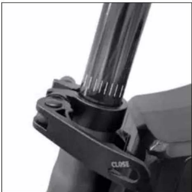
natural_image
Close-up of a mechanical clamp or bracket with a cylindrical component and a 'CLOSE' label (no readable text beyond the label)natural_image
Technical line drawing of two mechanical components with labeled parts (L and R), no text or symbols present! ATTENZIONE
natural_image
Close-up of a hand holding a black mechanical component with a yellow arrow indicating a motion or force direction (no text or symbols visible)Pedale aperto

natural_image
Close-up of a black bicycle brake mechanism with visible brackets and wheels (no text or symbols)Pedale chiuso
natural_image
Close-up of a black mechanical component with a metallic clip and mounting bracket (no visible text or symbols)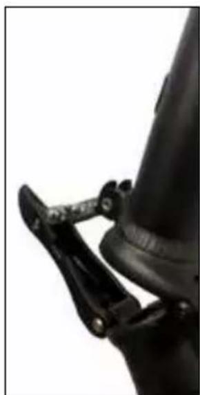
natural_image
Close-up of a black mechanical clamp securing a cylindrical component (no visible text or symbols)natural_image
Side view of a white and black electric scooter with a red and orange wheel, showing suspension components (no text or symbols visible)natural_image
Back view of a black electronic device with two labeled ports (15 and 16), no visible text or symbols beyond labels.natural_image
Exterior view of a black rectangular electronic device rear panel with labeled ports A and B (no additional text or symbols)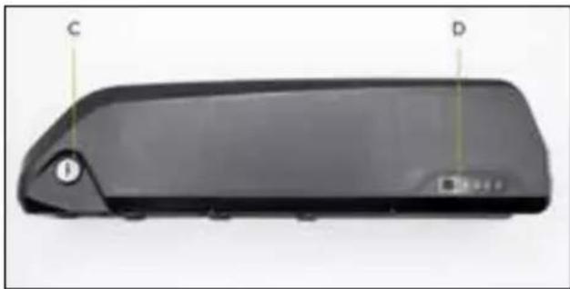
natural_image
Black rectangular electronic device with labeled points C and D, showing no visible text or symbols beyond labelsnatural_image
Exterior view of a black rectangular electronic device casing with labeled ports (D, C) and mounting holes (no text or symbols beyond labels)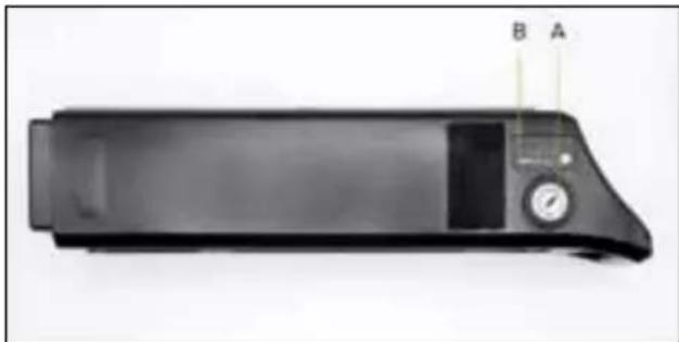
natural_image
Black electronic device with a digital display and labeled ports A and B (no visible text or symbols on the device body)natural_image
Black electronic device with two cables and a rectangular base, labeled A, B, C (no text or symbols on the device itself)natural_image
Symbol of a trash bin crossed with diagonal lines, no text or numbers presentnatural_image
Symbol of a trash bin crossed with no text or numbers, representing waste sorting or disposal (no text present)natural_image
Close-up of a mechanical linkage mechanism with a labeled point A (no text or symbols on the diagram itself)
natural_image
Close-up of a black mechanical component with a labeled arrow and scale bar (no text or symbols on the object itself)natural_image
Close-up of hands using a black wire stripper tool to adjust or install a cable (no text or symbols visible)natural_image
Close-up of a black mechanical clamp or bracket with a cylindrical rod inserted, no visible text or symbols.
natural_image
Close-up of a mechanical clamp or bracket with a cylindrical rod and a close button labeled 'CLOSE' (no other text or symbols visible)
natural_image
Close-up of a mechanical clamp or bracket with a cylindrical component and a 'CLOSE' label (no readable text beyond the label)natural_image
Technical line drawing of a mechanical component with labeled parts (L and R), showing assembly and mounting details without any text or symbols.! ATENCIÓN
natural_image
Close-up of a hand holding a black mechanical component with a yellow arrow indicating a motion or force direction (no text or symbols visible)Pedal abierto

natural_image
Close-up of a black bicycle brake mechanism with visible brackets and wheels (no text or symbols)Pedal cerrado
natural_image
Close-up of a black mechanical component with a metallic clip and mounting bracket (no visible text or symbols)
natural_image
Close-up of a black mechanical clamp securing a cylindrical component (no visible text or symbols)natural_image
Side view of a white and black electric scooter with red and orange racing tires, no visible text or symbols.natural_image
Back view of a black electronic device with two labeled ports (15 and 16), no visible text or symbols beyond labels.natural_image
Exterior view of a black rectangular electronic device rear panel with labeled ports A and B (no additional text or symbols)
natural_image
Black rectangular electronic device with labeled points C and D, no visible text or symbols on bodynatural_image
Black rectangular electronic device casing with labeled ports D and C (no text or symbols beyond labels)
natural_image
Black electronic device with a display and control panel, labeled A and B (no visible text or symbols on the device body)natural_image
Black electronic device with three labeled wires (A, B, C) and a power plug, shown against a plain background (no text or symbols on the device itself)natural_image
Symbol of a trash bin crossed with diagonal lines, no text or numbers presentnatural_image
Symbol of a trash bin crossed with no text or numbers, representing waste sorting or disposal (no text present)natural_image
Close-up of a mechanical linkage mechanism with a labeled point A (no text or symbols on the diagram itself)
natural_image
Close-up of a black mechanical component with a labeled arrow and scale bar (no text or symbols beyond the label)natural_image
Close-up of hands using a black wire stripper tool to adjust or install a metal pipe (no text or symbols visible)natural_image
Close-up of a mechanical clamp or bracket with a black cylindrical component and a 'CLOSE' label (no readable text beyond the label)DANGER
natural_image
Technical line drawing of a mechanical component with labeled parts (L, R) and directional arrows indicating motion or assembly (no text or symbols beyond labels)! ATTENTION
natural_image
Close-up of a hand holding a black mechanical component with a yellow arrow indicating a force or movement (no text or symbols visible)Pédale ouverte

natural_image
Close-up of a black bicycle brake mechanism with visible brackets and wheels (no text or symbols)Pédale fermée
natural_image
Close-up of a black mechanical component with a metallic clip and mounting bracket (no visible text or symbols)
natural_image
Close-up of a black mechanical clamp securing a cylindrical component (no visible text or symbols)natural_image
Side view of a white and black electric scooter with red and orange racing wheel (no visible text or symbols)natural_image
Back view of a black electronic device with two labeled ports (15 and 16), no visible text or symbols beyond labels.natural_image
Exterior view of a black rectangular electronic device with labeled ports A and B (no additional text or symbols)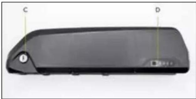
natural_image
Black rectangular electronic device with labeled points C and D, no visible text or symbols on bodynatural_image
Exterior view of a black rectangular electronic device casing with labeled ports (D, C) and mounting holes (no text or symbols beyond labels)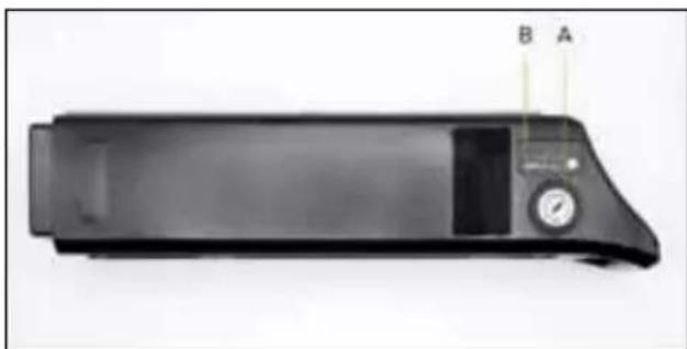
natural_image
Black rectangular electronic device with labeled ports A and B, no visible text or symbols on bodynatural_image
Black electronic device with two cables and a rectangular base, labeled A, B, C (no text or symbols on the device body)natural_image
Symbol of a trash bin crossed with diagonal lines, no text or numbers presentnatural_image
Symbol of a trash bin crossed with no text or numbers, representing waste sorting or disposal (no text present)natural_image
Close-up of a mechanical linkage mechanism with a labeled point A (no text or symbols on the diagram itself)
natural_image
Close-up of a black mechanical component with a labeled arrow and scale bar (no text or symbols on the object itself)natural_image
Close-up of hands using a black metal tool to adjust or install a pipe fitting (no visible text or symbols)natural_image
Close-up of a black mechanical component with a clamping tool (no visible text or symbols)
natural_image
Close-up of a mechanical clamp or bracket component with no visible text or symbolsnatural_image
Close-up of a mechanical clamp or bracket component with a cylindrical shaft and mounting base (no visible text or symbols)natural_image
Technical line drawing of a mechanical component with labeled parts (L, R) and directional arrows indicating motion or assembly (no text or symbols beyond labels)! VORSICHT
natural_image
Close-up of a hand holding a black mechanical component with a yellow arrow indicating a force or movement (no text or symbols visible)Offenes Pedal

natural_image
Close-up of a black bicycle brake mechanism with visible brackets and wheels (no text or symbols)Geschlossenes Pedal
natural_image
Close-up of a black mechanical component with a metallic clip and mounting bracket (no visible text or symbols)
natural_image
Close-up of a black mechanical clamp securing a cylindrical component (no visible text or symbols)natural_image
Side view of a white and black electric scooter with red and orange racing tires, no visible text or symbols.natural_image
Back view of a black electronic device with two labeled ports (15 and 16), no visible text or symbols beyond labels.natural_image
Exterior view of a black rectangular electronic device rear panel with labeled ports A and B (no additional text or symbols)
natural_image
Black rectangular electronic device with labeled points C and D, showing a handle and base (no text or symbols beyond labels)natural_image
Black rectangular electronic device casing with labeled ports (D, C) and mounting holes, no readable text or symbols beyond labels
natural_image
Black electronic device with labeled ports A and B, no visible text or symbols on bodynatural_image
Black electronic device with two cables and a rectangular base, labeled A, B, C (no text or symbols on the device itself)natural_image
Symbol of a trash bin crossed with diagonal lines, no text or numbers presentnatural_image
Symbol of a trash bin crossed with no text or numbers, representing waste sorting or disposal (no text present)natural_image
Close-up of a robotic arm gripping a mechanical component, with no visible text or symbols
natural_image
Close-up of a black mechanical lever with a labeled point A (no text or symbols on the lever itself)natural_image
Close-up of hands using a black wire stripper tool to adjust or install a metal pipe (no text or symbols visible)natural_image
Close-up of a mechanical clamp or bracket with a cylindrical rod and mounting holes (no visible text or symbols)NIEBEZPIECZEŃSTWO
natural_image
Close-up of a mechanical clamp or bracket with a cylindrical rod and a close button (no text or symbols visible)
natural_image
Close-up of a mechanical clamp or bracket component with no visible text or symbolsnatural_image
Technical line drawing of a mechanical component with labeled parts (L, R) and directional arrows indicating motion or assembly (no text or symbols beyond labels)
natural_image
Close-up of a hand holding a black mechanical component with a yellow arrow indicating a directional flow (no text or symbols visible)Otwarty pedał

natural_image
Close-up of a black bicycle brake mechanism with visible brackets and wheels (no text or symbols)Zamknięty pedał
natural_image
Close-up of a black mechanical component with a metallic clip and mounting bracket (no visible text or symbols)
natural_image
Close-up of a black mechanical clamp securing a cylindrical component (no visible text or symbols)natural_image
Side view of a white and black electric scooter with orange wheel rim, showing front wheel, rear wheel, and suspension seat (no text or symbols visible)natural_image
Back view of a black electronic device with two labeled ports (15 and 16), no visible text or symbols beyond labels.natural_image
Exterior view of a black rectangular electronic device with labeled ports A and B (no additional text or symbols)
natural_image
Black rectangular electronic device with labeled points C and D, no visible text or symbols on bodynatural_image
Exterior view of a black rectangular electronic device casing with labeled ports (D, C) and control buttons (no readable text or symbols beyond labels)
natural_image
Black rectangular electronic device with a dial and control panel, labeled A and B (no visible text or symbols on the device body)natural_image
Black electronic device with two cables and a rectangular connector, labeled A, B, C (no text or symbols on the device itself)natural_image
Symbol of a trash bin crossed with no text or numbers, representing environmental restriction (no text present)natural_image
Simple line drawing of a trash bin with crossed lines indicating no waste or discharge (no text or symbols)natural_image
Close-up of a robotic arm gripping a mechanical component, with no visible text or symbols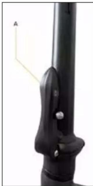
natural_image
Close-up of a black mechanical component with a labeled arrow and mounting bracket (no text or symbols on the object itself)Polohování řídítek
natural_image
Close-up of hands using a black metal tool to adjust or install a pipe fitting (no text or symbols visible)natural_image
Close-up of a mechanical clamp or bracket with a cylindrical rod and mounting holes (no visible text or symbols)
natural_image
Close-up of a mechanical clamp or bracket component with no visible text or symbols
natural_image
Close-up of a mechanical clamp or bracket component with a cylindrical shaft and mounting base (no visible text or symbols)natural_image
Technical line drawing of a mechanical component with labeled parts (L, R) and directional arrows indicating motion or assembly (no text or symbols beyond labels)! POZOR
natural_image
Close-up of a hand holding a black mechanical component with a yellow arrow indicating a directional flow (no text or symbols visible)Otevřený pedál

natural_image
Close-up of a black bicycle brake mechanism with visible brackets and wheels (no text or symbols)Zavřený pedál
natural_image
Close-up of a black mechanical component with a metallic clip and mounting bracket (no visible text or symbols)
natural_image
Close-up of a black mechanical clamp securing a cylindrical component (no visible text or symbols)natural_image
Side view of a white and black electric scooter with red and orange racing wheel (no visible text or symbols)natural_image
Back view of a black electronic device with two labeled ports (15 and 16), no visible text or symbols beyond labels.natural_image
Exterior view of a black rectangular electronic device with a small circular component and labeled points A and B (no text or symbols on the device itself)
natural_image
Black rectangular device with labeled points C and D, no visible text or symbols on the bodynatural_image
Exterior view of a black rectangular electronic device casing with labeled ports (D, C) and control buttons (no readable text or symbols beyond labels)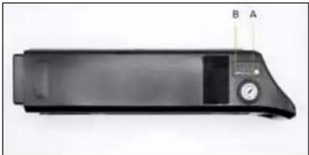
natural_image
Black rectangular electronic device with a dial and control panel, labeled A and B (no visible text or symbols on the device body)natural_image
Black electronic device with two cables and a rectangular base, labeled A, B, C (no text or symbols on the device itself)natural_image
Symbol of a trash bin crossed with diagonal lines, no text or numbers presentnatural_image
Symbol of a trash bin crossed with no text or numbers, representing waste sorting or disposal (no text present)natural_image
Close-up of a mechanical linkage mechanism with a labeled point A (no text or symbols on the diagram itself)
natural_image
Close-up of a black mechanical component with a labeled arrow and scale bar (no text or symbols on the object itself)natural_image
Close-up of hands using a black metal tool to adjust or install a pipe fitting (no visible text or symbols)natural_image
Close-up of a mechanical clamp or bracket component (no visible text or symbols)NEBEZPEČENSTVO
natural_image
Close-up of a mechanical clamp or bracket component with a cylindrical shaft and mounting bracket (no visible text or symbols)
natural_image
Close-up of a mechanical clamp or bracket component with no visible text or symbolsnatural_image
Technical line drawing of a mechanical component with labeled parts (L, R) and directional arrows indicating motion or assembly (no text or symbols beyond labels)
UPOZORNENIE
natural_image
Close-up of a hand holding a black mechanical component with a yellow arrow indicating a motion or force direction (no text or symbols visible)Pedál otvorený
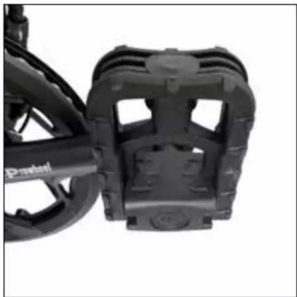
natural_image
Close-up of a black bicycle brake mechanism with visible brackets and wheels (no text or symbols)Pedál zatvorený
natural_image
Close-up of a black mechanical component with a metallic clip and mounting bracket (no visible text or symbols)
natural_image
Close-up of a black mechanical clamp securing a cylindrical component (no visible text or symbols)natural_image
Side view of a white and black electric scooter with red and orange racing tires, no visible text or symbols.natural_image
Back view of a black electronic device with two labeled ports (15 and 16), no visible text or symbols beyond labels.natural_image
Exterior view of a black rectangular electronic device with a small circular component and labeled points A and B (no text or symbols on the device itself)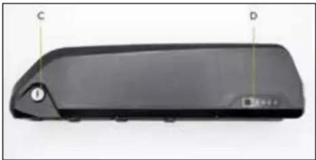
natural_image
Black rectangular device with labeled points C and D, no visible text or symbols on bodyA. Spínač aktivácie batérie (I=On / O=Off)
B. Nabíjacia zásuvka pre nabíjačku
C. Uzamknutie/odomknutie zámku batérie
D. Indikátor stavu zostatkového nabitia
natural_image
Exterior view of a black rectangular electronic device casing with labeled ports (D, C) and control buttons (no readable text or symbols beyond labels)
natural_image
Black rectangular electronic device with a dial and control panel, labeled A and B (no visible text or symbols on the device body)A. Aktivácia uzamknutie/odomknutie zámku batérie
B. Indikátor stavu zostatkového nabitia
C. Nabíjacia zásuvka pre nabíjačku
D. USB zásuvka pre nabíjanie prenosných zariadení
Vytahovanie a vkladanie batérie
natural_image
Black electronic device with two cables and a rectangular base, labeled A, B, C (no text or symbols on the device itself)natural_image
Simple line drawing of a trash bin with crossed lines indicating no waste or discharge (no text or symbols)natural_image
Symbol of a trash bin crossed with diagonal lines, no text or numbers presentnatural_image
Close-up of a mechanical linkage mechanism with a labeled point A (no text or symbols on the diagram itself)
natural_image
Close-up of a black mechanical component with a labeled arrow and scale bar (no text or symbols on the object itself)Postavitev krmila
natural_image
Close-up of hands using a black metal tool to adjust or install a pipe fitting (no text or symbols visible)natural_image
Close-up of a mechanical clamp or bracket with a cylindrical rod and a close button (no text or symbols visible)
natural_image
Close-up of a mechanical clamp or bracket with a cylindrical rod and a close button labeled 'CLOSE' (no other text or symbols visible)
natural_image
Close-up of a mechanical clamp or bracket with a cylindrical component inserted, no visible text or symbolsnatural_image
Technical line drawing of a mechanical component with labeled parts (L, R) and directional arrows indicating motion or assembly (no text or symbols beyond labels)! POZOR
natural_image
Close-up of a hand holding a black mechanical component with a yellow arrow indicating a force or movement (no text or symbols visible)Odprt pedal

natural_image
Close-up of a black bicycle brake mechanism with visible brackets and wheels (no text or symbols)Zaprt pedal
natural_image
Close-up of a black mechanical component with a metallic clip and mounting bracket (no visible text or symbols)
natural_image
Close-up of a black mechanical clamp securing a cylindrical component (no visible text or symbols)Zložite steblo krmila navzdol.


natural_image
Side view of a white and black electric scooter with red and orange racing tires, no visible text or symbols.natural_image
Back view of a black electronic device with two labeled ports (15 and 16), no visible text or symbols beyond labels.natural_image
Black electronic device with two cables and a plug, labeled A, B, C (no text or symbols on the device itself)A. Vtič za polnjenje baterije
B. Napajalni vtič
C. Opozorilna LED lučka za stanje napolnjenosti baterije
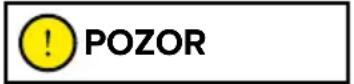
natural_image
Symbol of a trash bin crossed with diagonal lines, no text or numbers presentnatural_image
Symbol of a trash bin crossed with no text or numbers, representing waste sorting or disposal (no text present)natural_image
Close-up of a mechanical linkage mechanism with a labeled point A (no text or symbols on the diagram itself)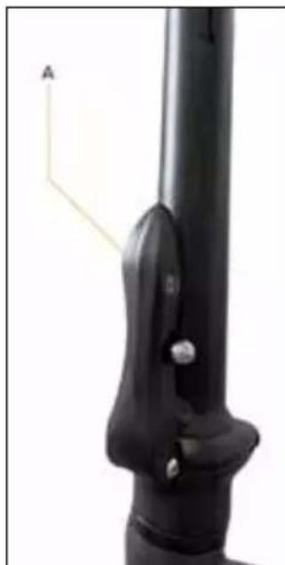
natural_image
Close-up of a black mechanical component with a labeled arrow and scale bar (no text or symbols on the object itself)Plaatsing stuur
natural_image
Close-up of hands using a black metal tool to adjust or install a pipe fitting (no visible text or symbols)natural_image
Close-up of a black mechanical component with a clamping tool (no visible text or symbols)
Minimumgrens inbrengen zadelpen
natural_image
Close-up of a mechanical clamp or bracket with a cylindrical rod and a close button labeled 'CLOSE' (no other text or symbols visible)natural_image
Close-up of a mechanical clamp or bracket component with a cylindrical shaft and mounting holes (no visible text or symbols)Installatie pedalen
natural_image
Technical line drawing of a mechanical component with labeled parts (L and R), showing assembly and mounting details without any text or symbols.! OPGELET
natural_image
Close-up of a hand holding a black mechanical component with a yellow arrow indicating a force or movement (no text or symbols visible)Pedaal open

natural_image
Close-up of a black bicycle brake mechanism with visible brackets and wheels (no text or symbols)Pedaal gesloten
natural_image
Close-up of a black mechanical component with a metallic clip and mounting bracket (no visible text or symbols)
natural_image
Close-up of a black mechanical clamp securing a cylindrical component (no visible text or symbols)natural_image
Side view of a white and black electric scooter with red accents, showing its suspension frame and wheel (no text or symbols visible)beschikbare opties = on / off
natural_image
Back view of a black electronic device with two labeled ports (15 and 16), no visible text or symbols beyond labels.trapondersteuning (P)
natural_image
Exterior view of a black rectangular electronic device rear panel with labeled ports A and B (no additional text or symbols)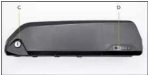
natural_image
Front view of a black rectangular electronic device with labeled points C and D, showing no visible text or symbols beyond labels.natural_image
Black rectangular electronic device casing with labeled ports D and C (no text or symbols on body)
natural_image
Black rectangular electronic device with a dial and control panel, labeled B and A (no visible text or symbols on the device body)natural_image
Black electronic device with two cables and a rectangular base, labeled A, B, C (no text or symbols on the device body)natural_image
Symbol of a trash bin crossed with a diagonal line, no text or numbers presentnatural_image
Simple line drawing of a trash bin with no text or symbolsDeclaration of Conformity
M.T. Distribution S.R.L
Address: Via Bargellino 10, 40012 Calderara di Reno (BO), Italy
This declaration of conformity is issued under the sole responsibility of the Manufacturer
| Product Brand: ARGENTO E-MOBILITY | |
| Product Model: Piuma | |
| Description of product: Electric Bike | |
| Rating: Product: DC 36V, 250W | |
Is in conformity with the requirements of the council Directives on the approximation of the laws of the Member States relating:
EU Council Directive 2004/108/EC Electromagnetic Compatibility EU MD 2006/42/EC Machinery Directive
Test Standards:
EN 15194: 2017
Factory name: Bikeelectric Quadrini Srl
Factory address: Loc. Dragoeni 10, Targu Jiu, Gorj, Romania
Date: 01/01/2020
Technical file available from EU headquarter
Declaration Place: Bologna, Italy
First name and surname: Alessandro Summa
Position: CEO
MT DISTRIBUTION S.R.L
Via Bargellino 10, 40012, Calderara di Reno (BO), Italy
Authorized person: Alessandro Summa
Position: CEO
NOTE:
This declaration of conformity is only applicable to Electric
Bike sold in countries that follow the CE marking directives.
CE
Declaration of Conformity
M.T. Distribution S.R.L
Address: Via Bargellino 10, 40012 Calderara di Reno (BO), Italy
This declaration of conformity is issued under the sole responsibility of the Manufacturer
| Product Brand: ARGENTO E-MOBILITY | |
| Product Model: Piuma+ | |
| Description of product: E | electric Bike |
| Rating: Product: DC 36V, | 250W |
Is in conformity with the requirements of the council Directives on the approximation of the laws of the Member States relating:
EU Council Directive 2004/108/EC Electromagnetic Compatibility EU MD 2006/42/EC Machinery Directive
Test Standards :
EN 15194: 2017
Factory name: Bikeelectric Quadrini Srl
Factory address: Loc. Dragoeni 10, Targu Jiu, Gorj, Romania
Date: 01/01/2020
Technical file available from EU headquarter
Declaration Place: Bologna, Italy
First name and surname: Alessandro Summa
Position: CEO
MT DISTRIBUTION S.R.L
Via Bargellino 10, 40012, Calderara di Reno (BO), Italy
Authorized person: Alessandro Summa
Position: CEO
NOTE:
This declaration of conformity is only applicable to Electric
Bike sold in countries that follow the CE marking directives.
CE
Declaration of Conformity
M.T. Distribution S.R.L
Address: Via Bargellino 10, 40012 Calderara di Reno (BO), Italy
This declaration of conformity is issued under the sole responsibility of the Manufacturer
| Product Brand: ARGENTO E-MOBILITY | |
| Product Model: Piuma-S | |
| Description of product: Electric Bike | |
| Rating: Product: DC 36V, 250W | |
Is in conformity with the requirements of the council Directives on the approximation of the laws of the Member States relating:
EU Council Directive 2004/108/EC Electromagnetic Compatibility EU MD 2006/42/EC Machinery Directive
Test Standards:
EN 15194: 2017
Factory name: Bikeelectric Quadrini Srl
Factory address: Loc. Dragoeni 10, Targu Jiu, Gorj, Romania
Date: 01/01/2020
Technical file available from EU headquarter
Declaration Place: Bologna, Italy
First name and surname: Alessandro Summa
Position: CEO
MT DISTRIBUTION S.R.L
Via Bargellino 10, 40012, Calderara di Reno (BO), Italy
Authorized person: Alessandro Summa
Position: CEO
NOTE:
This declaration of conformity is only applicable to Electric
Bike sold in countries that follow the CE marking directives.
CE
Declaration of Conformity
M.T. Distribution S.R.L
Address: Via Bargellino 10, 40012 Calderara di Reno (BO), Italy
This declaration of conformity is issued under the sole responsibility of the Manufacturer
| Product Brand: ARGENTO E-MOBILITY | |
| Product Model: Piuma-S+ | |
| Description of product: E | electric Bike |
| Rating: Product: DC 36V, | 250W |
Is in conformity with the requirements of the council Directives on the approximation of the laws of the Member States relating:
EU Council Directive 2004/108/EC Electromagnetic Compatibility EU MD 2006/42/EC Machinery Directive
Test Standards :
EN 15194: 2017
Factory name: Bikeelectric Quadrini Srl
Factory address: Loc. Dragoeni 10, Targu Jiu, Gorj, Romania
Date: 01/01/2020
Technical file available from EU headquarter
Declaration Place: Bologna, Italy
First name and surname: Alessandro Summa
Position: CEO
MT DISTRIBUTION S.R.L
Via Bargellino 10, 40012, Calderara di Reno (BO), Italy
Authorized person: Alessandro Summa
Position: CEO
NOTE:
This declaration of conformity is only applicable to Electric
Bike sold in countries that follow the CE marking directives.
CE
Declaration of Conformity
according to the EC Machinery Directive 2006/42/EC, Annex II 1.A.
This declaration of conformity is issued under the sole responsibility of the manufacturer.
Manufacturer: Asiabike Industrial Limited
114, Old Galle Road, Henamulla, Panadura, Sri Lanka.
Authorised representative: Platum By MT Distribution srl
Person authorized to compile the technical file: Jigang Guo
Object of the declaration:
| Model code Generic | denomination | Trademark Serial identification number (s) and/or batch number (s) |
| AR-BI-220003 Piuma | Silver ARGENTO E-MOBILITY AR1422XXXXX | |
| AR-BI-220004 Piuma | Blue ARGENTO E-MOBILITY AR1522XXXXX |
The object of the declaration described above fulfils all the relevant provisions of the following Directives:
Directive 2006/42/CE on machinery.
Directive 2014/30/EU on the harmonization of the laws of the Member States relating to electromagnetic compatibility.
Directive 2011/65/EU on the restriction of the use of certain hazardous substances in electrical and electronic equipment.
Harmonized standards or other technical specifications applied:
| EN ISO 12100:2010 EN 63000:2018 | |
| EN 15194:2017 |
Place of issue
Date of issue
Name, function, signature
Alessandro Summa, CEO
CE
Declaration of Conformity
according to the EC Machinery Directive 2006/42/EC, Annex II 1.A.
This declaration of conformity is issued under the sole responsibility of the manufacturer.
Manufacturer: Asiabike Industrial Limited
114, Old Galle Road, Henamulla, Panadura, Sri Lanka.
Authorised representative: Platum By MT Distribution srl
Person authorized to compile the technical file: Jigang Guo
Object of the declaration:
| Model code Generic | denomination | Trademark Serial identification number (s) and/or batch number (s) |
| AR-BI-220005 Piuma | S ARGENTO E-MOB | ILITY AR1622XXXXX |
The object of the declaration described above fulfils all the relevant provisions of the following Directives:
Directive 2006/42/CE on machinery.
Directive 2014/30/EU on the harmonization of the laws of the Member States relating to electromagnetic compatibility.
Directive 2011/65/EU on the restriction of the use of certain hazardous substances in electrical and electronic equipment.
Harmonized standards or other technical specifications applied:
| EN ISO 12100:2010 EN 63000:2018 | |
| EN 15194:2017 |
Place of issue
Date of issue
Name, function, signature
Alessandro Summa, CEO
#ATTITUDE ON THE MOVE

argentoemobility.com

Argento e-Mobility

argentoemobility

PLATUM
Shaping urban e-mobility
Imported and distributed by
M.T. Distribution Srl
via Bargellino 10 c/d, 40012,