
Fatal1ty 990FX Killer/3.1 - Motherboard ASROCK - Free user manual and instructions
Find the device manual for free Fatal1ty 990FX Killer/3.1 ASROCK in PDF.
User questions about Fatal1ty 990FX Killer/3.1 ASROCK
0 question about this device. Answer the ones you know or ask your own.
Ask a new question about this device
Download the instructions for your Motherboard in PDF format for free! Find your manual Fatal1ty 990FX Killer/3.1 - ASROCK and take your electronic device back in hand. On this page are published all the documents necessary for the use of your device. Fatal1ty 990FX Killer/3.1 by ASROCK.
USER MANUAL Fatal1ty 990FX Killer/3.1 ASROCK
Published January 2015
Copyright©2015 ASRock INC. All rights reserved.
Copyright Notice:
No part of this documentation may be reproduced, transcribed, transmitted, or translated in any language, in any form or by any means, except duplication of documentation by the purchaser for backup purpose, without written consent of ASRock Inc.
Products and corporate names appearing in this documentation may or may not be registered trademarks or copyrights of their respective companies, and are used only for identification or explanation and to the owners' benefit, without intent to infringe.
Disclaimer:
Specifications and information contained in this documentation are furnished for informational use only and subject to change without notice, and should not be constructed as a commitment by ASRock. ASRock assumes no responsibility for any errors or omissions that may appear in this documentation.
With respect to the contents of this documentation, ASRock does not provide warranty of any kind, either expressed or implied, including but not limited to the implied warranties or conditions of merchantability or fitness for a particular purpose.
In no event shall ASRock, its directors, officers, employees, or agents be liable for any indirect, special, incidental, or consequential damages (including damages for loss of profits, loss of business, loss of data, interruption of business and the like), even if ASRock has been advised of the possibility of such damages arising from any defect or error in the documentation or product.

This device complies with Part 15 of the FCC Rules. Operation is subject to the following two conditions:
(1) this device may not cause harmful interference, and
(2) this device must accept any interference received, including interference that may cause undesired operation.
CALIFORNIA, USA ONLY
The Lithium battery adopted on this motherboard contains Perchlorate, a toxic substance controlled in Perchlorate Best Management Practices (BMP) regulations passed by the California Legislature. When you discard the Lithium battery in California, USA, please follow the related regulations in advance.
"Perchlorate Material-special handling may apply, see www.dtsc.ca.gov/hazardouswaste/perchlorate"
ASRock Website: http://www.asrock.com

Manufactured under license under U.S. Patent Nos: 5,956,674; 5,974,380; 6,487,535; 7,003,467 & other U.S. and worldwide patents issued & pending. DTS, the Symbol, & DTS and the Symbol together is a registered trademark & DTS Connect, DTS Interactive, DTS Neo:PC are trademarks of DTS, Inc. Product includes software.
© DTS, Inc., All Rights Reserved.

Connect

Interactive

Neo:PC
Who knew that at age 19, I would be a World Champion PC gamer. When I was 13, I actually played competitive billiards in professional tournaments and won four or five games off guys who played at the highest level. I actually thought of making a career of it, but at that young age situations change rapidly. Because I've been blessed with great hand-eye coordination and a grasp of mathematics (an important element in video gaming) I gravitated to that activity.
GOING PRO
I started professional gaming in 1999 when I entered the CPL (Cyberathlete Professional League) tournament in Dallas and won \4,000 for coming in third place. Emerging as one of the top players in the United States, a company interested in sponsoring me flew me to Sweden to compete against the top 12 players in the world. I won 18 straight games, lost none, and took first place, becoming the number one ranked Quake III player in the world in the process. Two months later I followed that success by traveling to Dallas and defending my title as the world's best Quake III player, winning the \40,000 grand prize. From there I entered competitions all over the world, including Singapore, Korea, Germany, Australia, Holland and Brazil in addition to Los Angeles, New York and St. Louis.
WINNING STREAK
I was excited to showcase my true gaming skills when defending my title as CPL Champion of the year at the CPL Winter 2001 because I would be competing in a totally different first person shooter (fps) game, Alien vs. Predator II. I won that competition and walked away with a new car. The next year I won the same title playing Unreal Tournament 2003, becoming the only three-time CPL champion of the year. And I did it playing a different game each year, something no one else has ever done and a feat of which I am extremely proud.
At QuakeCon 2002, I faced off against my rival ZeRo4 in one of the most highly anticipated matches of the year, winning in a 14 to (-1) killer victory. Competing at Quakecon 2004, I became the World's 1st Doom3 Champion by defeating Daler in a series of very challenging matches and earning \$25,000 for the victory.
Since then Fatality has traveled the globe to compete against the best in the world, winning prizes and acclaim, including the 2005 CPL World Tour Championship in New York City for a \$150,000 first place triumph. In August 2007, Johnathan was awarded the first ever Lifetime Achievement Award in the four year history of the eSports-Award for “showing exceptional sportsmanship, taking part in shaping eSports into what it is today and for being the prime representative of this young sport. He has become the figurehead for eSports worldwide”.
LIVIN' LARGE
Since my first big tournament wins, I have been a “Professional Cyberathlete”, traveling the world and livin’ large with lots of International media coverage on outlets such as MTV, ESPN and a 60 Minutes segment on CBS to name only a few. It's unreal - it's crazy. I'm living a dream by playing video games for a living. I've always been athletic and took sports like hockey and football very seriously, working out and training hard. This discipline helps me become a better gamer and my drive to be the best has opened the doors necessary to become a professional.
A DREAM
Now, another dream is being realized – building the ultimate gaming computer, made up of the best parts under my own brand. Quality hardware makes a huge difference in competitions...a couple more frames per second and everything gets really nice. It's all about getting the computer processing faster and allowing more fluid movement around the maps.
My vision for Fatal1ty hardware is to allow gamers to focus on the game without worrying about their equipment, something I've preached since I began competing. I don't want to worry about my equipment. I want to be there – over and done with - so I can focus on the game. I want it to be the fastest and most stable computer equipment on the face of the planet, so quality is what Fatal1ty Brand products represent.

Johnathan "Fatal1ty" Wendel

natural_image
Stylized portrait of a person in red and black tones (no text or symbols)Motherboard Layout
text_image
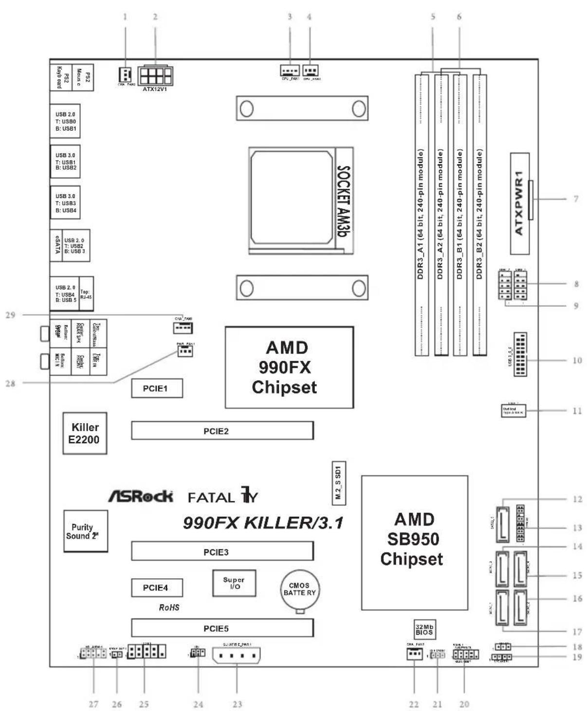
PS2 Key: bit PS2 Music ATX12V1 USB 2.0 T: USB0 B: USB1 USB 3.0 T: USB1 B: USB2 USB 3.0 T: USB3 B: USB4 GSATA USB 2.0 T: USB2 B: USB 3 USB 2.0 T: USB4 B: USB 5 Top: RJ-45 PCIE1 PCI7_ZMM PCIE2 AMD 990FX Chipset Killer E2200 ASRock FATAL 1Y 990FX KILLER/3.1 Purity Sound 2# PCIE3 PCIE4 Super I/O CMOS BATTERY RoHS PCIE5 AMD SB950 Chipset 32Mb BIOS ATXPWR1 DDR3_A1 (64 bit, 240-pin module) DDR3_A2 (64 bit, 240-pin module) DDR3_B1 (64 bit, 240-pin module) DDR3_B2 (64 bit, 240-pin module) M.2_S SD1 M.2_S SD1 PCIE5 PCIE4 PCIE3 PCIE1 PCIE2 PCIE1 PCIE3A ATX12V1 SOCKET AM3p AMD 990FX ChipsetNo. Description
1 Chassis Fan Connector (CHA_FAN2)
2 ATX 12V Power Connector (ATX12V1)
3 CPU Fan Connector (CPU_FAN1)
4 CPU Fan Connector (CPU_FAN2)
5 2 x 240-pin DDR3 DIMM Slots (DDR3_A1, DDR3_B1)
6 2 x 240-pin DDR3 DIMM Slots (DDR3_A2, DDR3_B2)
7 ATX Power Connector (ATXPWR1)
8 USB 2.0 Header (USB8_9)
9 USB 2.0 Header (USB6_7)
10 USB 3.0 Header (USB3_5_6)
11 Vertical Type A USB 3.0 (USB3_7)
12 SATA3 Connector (SATA3_5)
13 TPM Header (TPMS1)
14 SATA3 Connector (SATA3_3)
15 SATA3 Connector (SATA3_4)
16 SATA3 Connector (SATA3_2)
17 SATA3 Connector (SATA3_1)
18 Power LED Header (PLED1)
19 Chassis Speaker Header (SPEAKER1)
20 System Panel Header (PANEL1)
21 Clear CMOS Jumper (CLRCMOS1)
22 Chassis Fan Connector (CHA_FAN3)
23 PCIe Power Connector (SLI/XFIRE_PWR1)
24 Infrared Module Header (IR1)
25 COM Port Header (COM1)
26 SPDIF Out Connector (SPDIF_OUT1)
27 Front Panel Audio Header (HD_AUDIO1)
28 Power Fan Connector (PWR_FAN1)
29 Chassis Fan Connector (CHA_FAN1)
I/O Panel
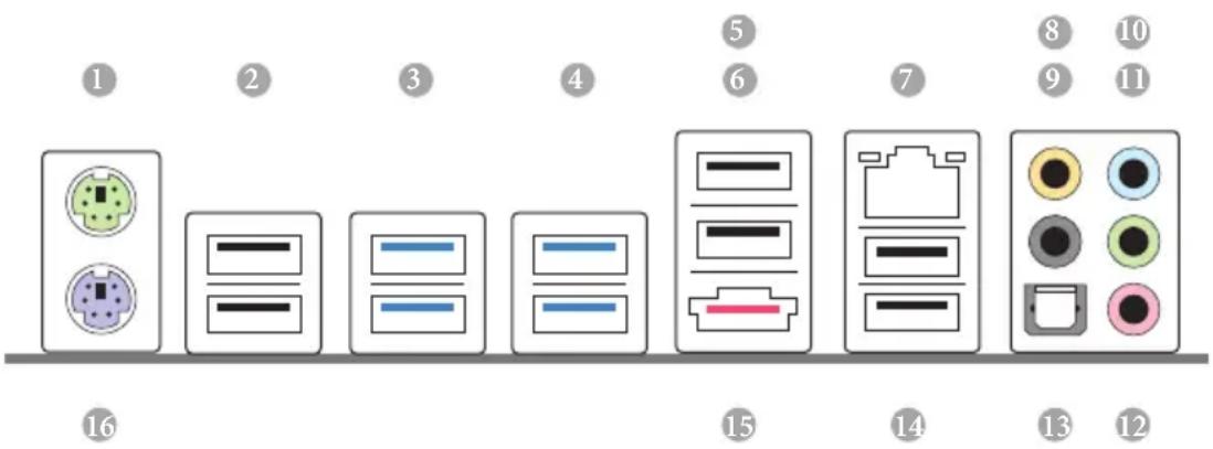
text_image
Diagram showing 16 labeled electronic device components with icons and numbers, likely representing a rack or connector layout.No. Description No. Description
1 PS/2 Mouse Port 9 Rear Speaker (Black)
2 USB 2.0 Ports (USB_01) 10 Line In (Light Blue)
3 USB 3.0 Ports (USB3_12) 11 Front Speaker (Lime)**
4 USB 3.0 Ports (USB3_34) 12 Microphone (Pink)
5 Fatal1ty Mouse Port (USB2) 13 Optical SPDIF Out Port
6 USB 2.0 Port (USB3) 14 USB 2.0 Ports (USB_45)
7 LAN RJ-45 Port ^ 15 eSATA3 Port (ESATA1) ^**
8 Central / Bass (Orange) 16 PS/2 Keyboard Port
* There are two LEDs on each LAN port. Please refer to the table below for the LAN port LED indications.
| Activity / Link LED Speed LED | |||
| Status Description Status Description | |||
| Off No Link Off | 10Mbps connection | ||
| Blinking Data Activity Orange 100Mbps connection | |||
| On Link Green 1Gbps connection | |||
** If you use a 2-channel speaker, please connect the speaker's plug into "Front Speaker Jack". See the table below for connection details in accordance with the type of speaker you use.
| Audio Output Channels | Front Speaker (No. 11) | Rear Speaker (No. 9) | Central / Bass (No. 8) | Line In (No. 10) |
| 2 V -- -- -- | ||||
| 4 V V -- -- | ||||
| 6 V V V -- | ||||
| 8 V V V V |

To enable Multi-Streaming, you need to connect a front panel audio cable to the front panel audio header. After restarting your computer, you will find the "Mixer" tool on your system. Please select "Mixer ToolBox" click "Enable playback multi-streaming", and click "ok". Choose "2CH", "4CH", "6CH", or "8CH" and then you are allowed to select "Realtek HDA Primary output" to use the Rear Speaker, Central/Bass, and Front Speaker, or select "Realtek HDA Audio 2nd output" to use the front panel audio.
*** The eSATA3 port supports SATA Gen3 in cable 1M. The eSATA3 port is shared with M.2_SSD (NGFF) Socket 3.
Chapter 1 Introduction
Thank you for purchasing ASRock Fatal1ty 990FX Killer/3.1 Series motherboard, a reliable motherboard produced under ASRock's consistently stringent quality control. It delivers excellent performance with robust design conforming to ASRock's commitment to quality and endurance.

Because the motherboard specifications and the BIOS software might be updated, the content of this manual will be subject to change without notice. In case any modifications of this manual occur, the updated version will be available on ASRock's website without further notice. If you require technical support related to this motherboard, please visit our website for specific information about the model you are using. You may find the latest VGA cards and CPU support list on ASRock's website as well. ASRock website http://www.asrock.com.
1.1 Package Contents
• ASRock Fatal1ty 990FX Killer/3.1 Series Motherboard (ATX Form Factor)
• ASRock Fatality 990FX Killer/3.1 Series Quick Installation Guide
• ASRock Fatal1ty 990FX Killer/3.1 Series Support CD
- 4 x Serial ATA (SATA) Data Cables (Optional)
- 1 x I/O Panel Shield
• 1 x ASRock USB 3.1/A+C
• 1 x ASRock SLI_Bridge_2S Card
• 1 x M.2_SSD (NGFF) Socket 3 Screw
1.2 Specifications
Platform
- ATX Form Factor
- Premium Gold Capacitor design (100% Japan-made high-quality conductive polymer capacitors)
• High Density Glass Fabric PCB
CPU
• Supports Socket AM3+ processors
- Supports Socket AM3 processors: AMD Phenom ^TM II X6 / X4 / X3 / X2 (except 920 / 940) / Athlon II X4 / X3 / X2 / Sempron processors
• Supports 8-Core CPU
• Supports UCC feature (Unlock CPU Core)
- Digi Power design
- 8 + 2 Power Phase design
• Supports CPU up to 140W
• Supports AMD's Cool 'n' Quiet Technology
• FSB 2600 MHz (5.2 GT/s)
• Supports Untied Overclocking Technology
• Supports Hyper-Transport 3.0 (HT 3.0) Technology
Chipset
• Northbridge: AMD 990FX
- Southbridge: AMD SB950
Memory
• Dual Channel DDR3 Memory Technology
- 4 x DDR3 DIMM Slots
- Supports DDR3 2450(OC)/2100(OC)/1600/1333/1066 non-ECC, un-buffered memory (see CAUTION1)
• Max. capacity of system memory: 64GB (see CAUTION2)
• Supports Intel® Extreme Memory Profile (XMP) 1.3 / 1.2
• Supports AMD Memory Profile (AMP)
Expansion
- 3 x PCI Express 2.0 x16 Slots (PCIE2/PCIE3 @ x16 mode; PCIE5 @ x4 mode)
• 2 x PCI Express 2.0 x1 Slots - Supports AMD Quad CrossFireX ^TM , 3-Way CrossFireX ^TM and CrossFireX ^TM
• Supports NVIDIA ^® Quad SLI ^TM and SLI ^TM
Audio
- 7.1 CH HD Audio with Content Protection (Realtek ALC1150 Audio Codec)
• Premium Blu-ray Audio support
• Supports Purity Sound ^TM 2 - Nichicon Fine Gold Series Audio Caps
- 115dB SNR DAC with Differential Amplifier
- TI® NE5532 Premium Headset Amplifier (Supports up to 600 Ohm headsets)
- Direct Drive Technology
- EMI Shielding Cover
- PCB Isolate Shielding
• Supports DTS Connect
LAN
• PCIE x1 Gigabit LAN 10/100/1000 Mb/s
• Qualcomm® Atheros® Killer™ E2200 Series
• Supports Wake-On-LAN
- Supports Lightning/ESD Protection (ASRock Full Spike Protection)
• Supports Energy Efficient Ethernet 802.3az
- Supports PXE
Rear Panel I/O
• 1 x PS/2 Mouse Port
• 1 x PS/2 Keyboard Port
• 1 x Optical SPDIF Out Port
- 5 x USB 2.0 Ports (Supports ESD Protection (ASRock Full Spike Protection))
- 1 x Fatality Mouse Port (USB 2.0) (Supports ESD Protection (ASRock Full Spike Protection))
- 4 x USB 3.0 Ports (ASMedia Hub) (Supports ESD Protection (ASRock Full Spike Protection))
• 1 x eSATA3 Connector
- 1 x RJ-45 LAN Port with LED (ACT/LINK LED and SPEED LED)
- HD Audio Jacks: Rear Speaker / Central / Bass / Line in / Front Speaker / Microphone
| ASRockUSB 3.1/A+C | 1 x USB 3.1 Type-A Port (10 Gb/s) (Supports ESD Protection (ASRock Full Spike Protection))1 x USB 3.1 Type-C Port (10 Gb/s) (Supports ESD Protection (ASRock Full Spike Protection)) |
| Storage | 5 x SATA3 6.0 Gb/s Connectors, support RAID (RAID 0, RAID 1, RAID 0+1, JBOD and RAID 5), NCQ, AHCI and Hot Plug1 x M.2_SSD (NGFF) Socket 3, supports M.2 SATA3 6.0 Gb/s module and M.2 PCI Express module up to Gen2 x2 (10 Gb/s) (M.2_SSD (NGFF) Socket 3 is shared with the eSATA3 connector) |
| Connector | 1 x IR Header1 x COM Port Header1 x TPM Header1 x Power LED Header2 x CPU Fan Connectors (1 x 4-pin, 1 x 3-pin)3 x Chassis Fan Connectors (1 x 4-pin, 2 x 3-pin)1 x Power Fan Connector (3-pin)1 x 24 pin ATX Power Connector1 x 8 pin 12V Power Connector (Hi-Density Power Connector)1 x PCIe Power Connector (see CAUTION3)1 x Front Panel Audio Connector1 x SPDIF Out Connector2 x USB 2.0 Headers (Support 4 USB 2.0 ports) (Supports ESD Protection (ASRock Full Spike Protection))1 x Vertical Type A USB 3.0 (Supports ESD Protection (ASRock Full Spike Protection))1 x USB 3.0 Header by Etron EJ188 (Supports 2 USB 3.0 ports) (Supports ESD Protection (ASRock Full Spike Protection)) |
| BIOSFeature | 32Mb AMI UEFI Legal BIOS with with GUI supportSupports “Plug and Play”ACPI 1.1 Compliant wake up eventsSupports jumperfreeSMBIOS 2.3.1 supportCPU, DRAM, NB, HT, CPU VDDA, PCIE VDDA, CPU NB Voltage multi-adjustment |
Hardware Monitor
• CPU/Chassis temperature sensing
• CPU/Chassis/Power Fan Tachometer
- CPU/Chassis Quiet Fan (Auto adjust fan speed by CPU temperature)
• CPU/Chassis Fan multi-speed control
• Voltage monitoring: +12V, +5V, +3.3V, CPU Vcore Voltage
os
- Microsoft® Windows® 10 64-bit / 8.1 32-bit / 8.1 64-bit / 8 32-bit / 8 64-bit / 7 32-bit / 7 64-bit
Certifications
- FCC, CE, WHQL
- ErP/EuP ready (ErP/EuP ready power supply is required)
* For detailed product information, please visit our website: http://www.asrock.com

Please realize that there is a certain risk involved with overclocking, including adjusting the setting in the BIOS, applying Untied Overclocking Technology, or using third-party overclocking tools. Overclocking may affect your system's stability, or even cause damage to the components and devices of your system. It should be done at your own risk and expense. We are not responsible for possible damage caused by overclocking.

- Whether 2450/2100MHz memory speed is supported depends on the AM3/AM3+ CPU you adopt. If you want to adopt DDR3 2450/2100 memory module on this motherboard, please refer to the memory support list on our website for the compatible memory modules. ASRock website: http://www.asrock.com
- Due to the operating system limitation, the actual memory size may be less than 4GB for the reservation for system usage under Windows* 8.1 / 8 / 7. For Windows* 64-bit OS with 64-bit CPU, there is no such limitation. You can use ASRock XFast RAM to utilize the memory that Windows* cannot use.
- Please plug the power cable to the PCIe power connector only when you install three or more VGA cards.
Chapter 2 Installation
This is an ATX form factor motherboard. Before you install the motherboard, study the configuration of your chassis to ensure that the motherboard fits into it.
Pre-installation Precautions
Take note of the following precautions before you install motherboard components or change any motherboard settings.
- Make sure to unplug the power cord before installing or removing the motherboard. Failure to do so may cause physical injuries to you and damages to motherboard components.
- In order to avoid damage from static electricity to the motherboard's components, NEVER place your motherboard directly on a carpet. Also remember to use a grounded wrist strap or touch a safety grounded object before you handle the components.
- Hold components by the edges and do not touch the ICs.
- Whenever you uninstall any components, place them on a grounded anti-static pad or in the bag that comes with the components.
- When placing screws to secure the motherboard to the chassis, please do not over-tighten the screws! Doing so may damage the motherboard.
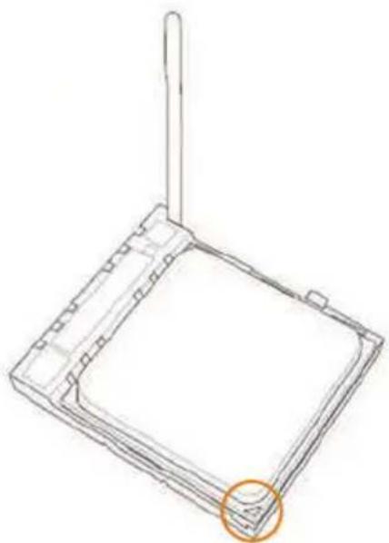
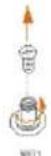
2.1 Installing the CPU

Unplug all power cables before installing the CPU.
1
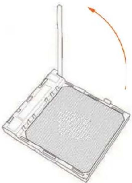
natural_image
Diagram of a device with a grid pattern and an orange curved arrow indicating rotation (no text or symbols)2
natural_image
Technical line drawing of a square mechanical component with a protruding rod and an orange circle highlighting a feature (no text or symbols)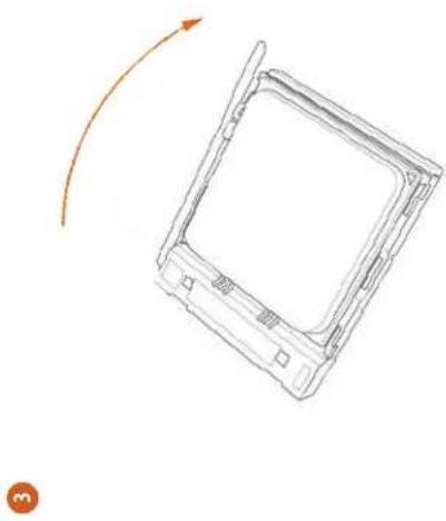
natural_image
Line drawing of a rectangular device with an arrow indicating rotation or movement (no text or symbols)English
年 12
2.2 Installing the CPU Fan and Heatsink
After you install the CPU into this motherboard, it is necessary to install a larger heatsink and cooling fan to dissipate heat. You also need to spray thermal grease between the CPU and the heatsink to improve heat dissipation. Make sure that the CPU and the heatsink are securely fastened and in good contact with each other. Then connect the CPU fan to the CPU FAN connector. For proper installation, please kindly refer to the instruction manuals of the CPU fan and the heatsink.

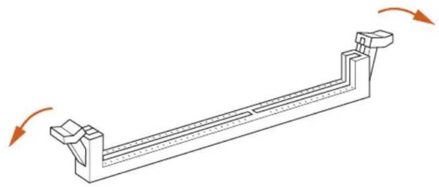
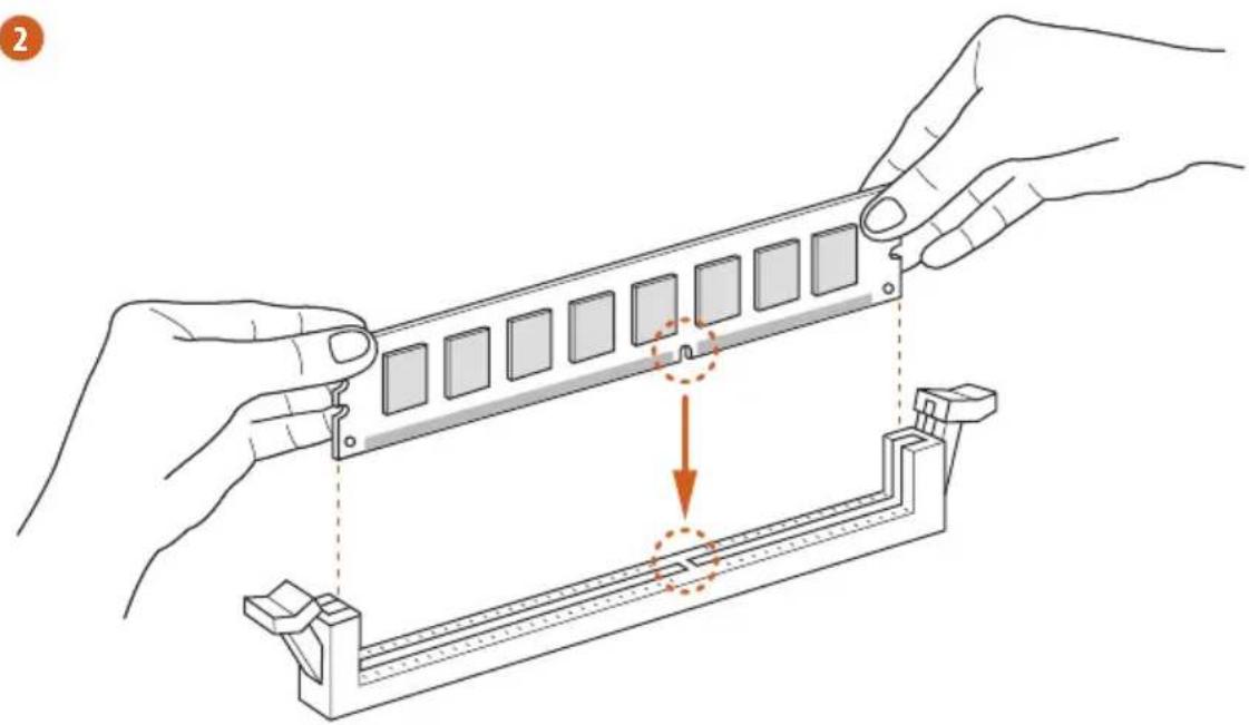
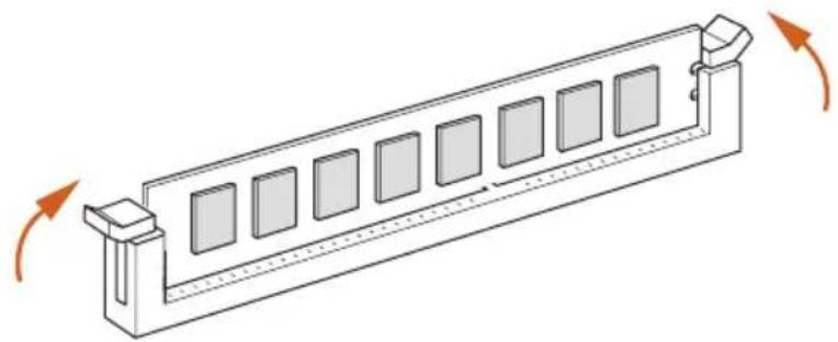
2.3 Installing Memory Modules (DIMM)
This motherboard provides four 240-pin DDR3 (Double Data Rate 3) DIMM slots, and supports Dual Channel Memory Technology.

- For dual channel configuration, you always need to install identical (the same brand, speed, size and chip-type) DDR3 DIMM pairs.
- It is unable to activate Dual Channel Memory Technology with only one or three memory module installed.
- It is not allowed to install a DDR or DDR2 memory module into a DDR3 slot; otherwise, this motherboard and DIMM may be damaged.
- Please install the memory module into DDR3_A2 and DDR3_B2 slots for the first priority.
- If you adopt DDR3 2450/2100 memory modules on this motherboard, it is recommended to install them on DDR3_A2 and DDR3_B2 slots.
Dual Channel Memory Configuration
Priority DDR3_A1 DDR3_A2 DDR3_B1 DDR3_B2
| 1 Populated Populated | |||
| 2 Populated Populated | |||
| 3 Populated Populated Populated Populated |

The DIMM only fits in one correct orientation. It will cause permanent damage to the motherboard and the DIMM if you force the DIMM into the slot at incorrect orientation.
1
natural_image
Technical line drawing of a mechanical support structure with rotational arrows indicating motion (no text or symbols)2
natural_image
Illustration of hands assembling a mechanical component with a highlighted section (no text or symbols)3
natural_image
Isometric line drawing of a rectangular structure with multiple square panels and directional arrows indicating rotation (no text or symbols)2.4 Expansion Slots (PCI Express Slots)
There are 5 PCI Express slots on the motherboard.

Before installing an expansion card, please make sure that the power supply is switched off or the power cord is unplugged. Please read the documentation of the expansion card and make necessary hardware settings for the card before you start the installation.
PCIe slots:
PCIE1 (PCIe 2.0 x1 slots) is used for PCI Express x1 lane width cards.
PCIE2 (PCIe 2.0 x16 slot) is used for PCI Express x16 lane width graphics cards.
PCIE3 (PCIe 2.0 x16 slot) is used for PCI Express x16 lane width graphics cards.
PCIE4 (PCIe 2.0 x1 slots) is used for PCI Express x1 lane width cards.
PCIE5 (PCIe 2.0 x16 slot) is used for PCI Express x4 lane width graphics cards
PCIe Slot Configurations
PCIE2 PCIE3 PCIE5
Single Graphics Card x16 N/A N/A
Two Graphics Cards in CrossFireX ^TM or SLI ^TM Mode
x16 x16 N/A
Three Graphics Cards in 3-Way CrossFireX™ Mode
x16 x16 x4

For a better thermal environment, please connect a chassis fan to the motherboard's chassis fan connector (CHA_FAN1, CHA_FAN2 or CHA_FAN3) when using multiple graphics cards.
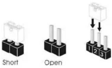
2.5 Jumpers Setup
The illustration shows how jumpers are setup. When the jumper cap is placed on the pins, the jumper is "Short". If no jumper cap is placed on the pins, the jumper is "Open". The illustration shows a 3-pin jumper whose pin1 and pin2 are "Short" when a jumper cap is placed on these 2 pins.
text_image
Short Open 1 2 3Clear CMOS Jumper (CLRCMOS1)
(see p.1, No. 21)
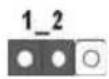
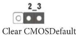
CLRCMOS1 allows you to clear the data in CMOS. To clear and reset the system parameters to default setup, please turn off the computer and unplug the power cord from the power supply. After waiting for 15 seconds, use a jumper cap to short pin2 and pin3 on CLRCMOS1 for 5 seconds. However, please do not clear the CMOS right after you update the BIOS. If you need to clear the CMOS when you just finish updating the BIOS, you must boot up the system first, and then shut it down before you do the clear-CMOS action. Please be noted that the password, date, time, and user default profile will be cleared only if the CMOS battery is removed.
2.6 Onboard Headers and Connectors

Onboard headers and connectors are NOT jumpers. Do NOT place jumper caps over these headers and connectors. Placing jumper caps over the headers and connectors will cause permanent damage to the motherboard.
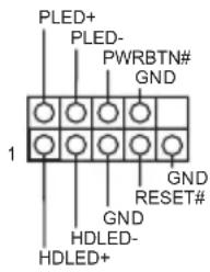
System Panel Header (9-pin PANEL1) (see p.1, No. 20)
text_image
PLED+ PLED- PWRBTN# GND 1 GND RESET# GND HDLED- HDLED+Connect the power switch, reset switch and system status indicator on the chassis to this header according to the pin assignments below. Note the positive and negative pins before connecting the cables.

PWRBTN (Power Switch):
Connect to the power switch on the chassis front panel. You may configure the way to turn off your system using the power switch.
RESET (Reset Switch):
Connect to the reset switch on the chassis front panel. Press the reset switch to restart the computer if the computer freezes and fails to perform a normal restart.
PLED (System Power LED):
Connect to the power status indicator on the chassis front panel. The LED is on when the system is operating. The LED keeps blinking when the system is in S1/S3 sleep state. The LED is off when the system is in S4 sleep state or powered off (S5).
HDLED (Hard Drive Activity LED):
Connect to the hard drive activity LED on the chassis front panel. The LED is on when the hard drive is reading or writing data.
The front panel design may differ by chassis. A front panel module mainly consists of power switch, reset switch, power LED, hard drive activity LED, speaker and etc. When connecting your chassis front panel module to this header, make sure the wire assignments and the pin assignments are matched correctly.
| Power LED Header(3-pin PLED1)(see p.1, No. 18) | 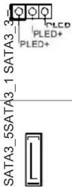 | Please connect the chassis power LED to this header to indicate the system's power status. |
| Serial ATA3 Connectors(SATA3_1:see p.1, No. 17)(SATA3_2:see p.1, No. 16)(SATA3_3:see p.1, No. 14)(SATA3_4:see p.1, No. 15)(SATA3_5:see p.1, No. 12) | 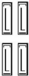 SATA3_2 SATA3_4 SATA3_2 SATA3_4 | These five SATA3 connectors support SATA data cables for internal storage devices with up to 6.0 Gb/s data transfer rate. |
| USB 2.0 Headers(9-pin USB6_7)(see p.1, No. 9)(9-pin USB8_9)(see p.1, No. 8) | 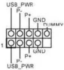 | Besides six USB 2.0 ports on the I/O panel, there are two headers on this motherboard. Each USB 2.0 header can support two ports. |
| USB 3.0 Headers(19-pin USB3_5_6)(see p.1, No. 10) | 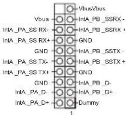 | Besides four USB 3.0 ports on the I/O panel, there is one header and one port on this motherboard. Each USB 3.0 header can support two ports. |
| (USB3_7)(see p.1, No. 11) |  |
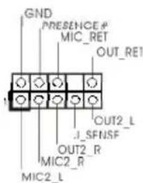
Front Panel Audio Header (9-pin HD_AUDIO1) (see p.1, No. 27)
text_image
GND PRESENCE # MIC_RET OUT_RE1 OUT2_L J_SFNSF OUT2_R MIC2_R MIC2_LThis header is for connecting audio devices to the front audio panel.

-
High Definition Audio supports Jack Sensing, but the panel wire on the chassis must support HDA to function correctly. Please follow the instructions in our manual and chassis manual to install your system.
-
If you use an AC'97 audio panel, please install it to the front panel audio header by the steps below:
A. Connect Mic_IN (MIC) to MIC2_L.
B. Connect Audio_R (RIN) to OUT2_R and Audio_L (LIN) to OUT2_L.
C. Connect Ground (GND) to Ground (GND).
D. MIC_RET and OUT_RET are for the HD audio panel only. You don't need to connect them for the AC'97 audio panel.
E. To activate the front mic, go to the "FrontMic" Tab in the Realtek Control panel and adjust "Recording Volume".
Chassis Speaker Header
(4-pin SPEAKER1)
(see p.1, No. 19)
DUMMY SPEAKER
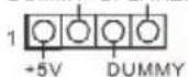
Please connect the chassis speaker to this header.
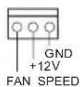
Chassis and Power Fan
Connectors
(4-pin CHA_FAN1)
(see p.1, No. 29)
Please connect fan cables to the fan connectors and match the black wire to the ground pin.
(3-pin CHA_FAN2)
(see p.1, No. 1)

(3-pin CHA_FAN3)
(see p.1, No. 22)
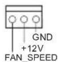
(3-pin PWR_FAN1)
(see p.1, No. 28)
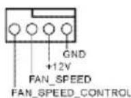
CPU Fan Connectors
(4-pin CPU_FAN1)
(see p.1, No. 3)
(3-pin CPU_FAN2)
(see p.1, No. 4)

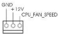
This motherboard provides a 4-Pin CPU fan
(Quiet Fan) connector.
If you plan to connect a
3-Pin CPU fan, please
connect it to Pin 1-3.
ATX Power Connector
(24-pin ATXPWR1)
(see p.1, No. 7)
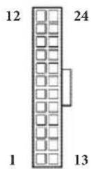
This motherboard pro-
vides a 24-pin ATX power
connector. To use a 20-pin
ATX power supply, please
plug it along Pin 1 and Pin
13.
ATX 12V Power
Connector
(8-pin ATX12V1)
(see p.1, No. 2)
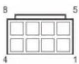
This motherboard pro-
vides an 8-pin ATX 12V
power connector. To use a
4-pin ATX power supply,
please plug it along Pin 1
and Pin 5.
PCIe Power Connector
(4-pin SLI/XFIRE_
PWR1)
(see p.1, No. 23)
Please connect this
connector with a hard
disk power connector
when three graphics
cards are installed on this
motherboard.
Infrared Module Header
(5-pin IR1)
(see p.1, No. 24)
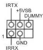
This header supports an optional
wireless transmitting and
receiving infrared module.
Serial Port Header
(9-pin COM1)
(see p.1, No. 25)
This COM1 header supports a serial port module.
SPDIF Out Connector
(2-pin SPDIF_OUT1)
(see p.1, No. 26)

Please connect the
SPDIF_OUT connector of a HDMI VGA card to this header with a cable.
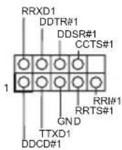
TPM Header
(17-pin TPMS1)
(see p.1, No. 13)
text_image
GNDF_CLKRUN# +3VSB SERIRQ# S_PWRDWN# GND LAD0_L +3V LAD1_L LAD2_L LAD3_L SMB_DATA_MA_IN TPM_RST# SMB_CLK_MAIN LFRAME#_L GND CK_33M_TPM 1This connector supports
Trusted Platform Module (TPM) system, which can securely store keys, digital certificates, passwords, and data. A TPM system also helps enhance network security, protects digital identities, and ensures platform integrity.
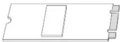
2.7 M.2\_SSD (NGFF) Module Installation Guide
The M.2, also known as the Next Generation Form Factor (NGFF), is a small size and versatile card edge connector that aims to replace mPCIe and mSATA. The M.2_SSD (NGFF) Socket 3 can accommodate either a M.2 SATA3 6.0 Gb/s module or a M.2 PCI Express module up to Gen 2 x2 (10 Gb/s). Please be noted that the M.2_SSD (NGFF) Socket 3 is shared with the eSATA3 connector; you can only choose either the M.2_SSD (NGFF) Socket 3 or the eSATA3 connector to use.
Installing the M.2_SSD (NGFF) Module
natural_image
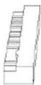
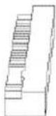
Pure technical line drawing of a rectangular component with notches, no text or symbols presentStep 1
Prepare a M.2_SSD (NGFF) module.


Step 2
Uninstall the screw knob and the standoff counterclockwise for later use.
text_image
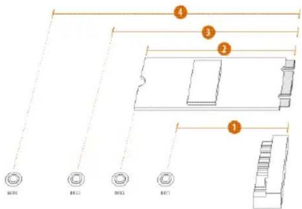
4 3 2 1 M100 M123 M125 M171Step 3
Depending on the PCB length of your M.2_SSD (NGFF) module, find the corresponding NUT location to be used.
No.1234
Location NUT1 NUT2 NUT3 NUT4
PCB Length 4.2cm 6cm 8cm 11cm
Module Type Type 2242 Type2260 Type 2280 Type 22110


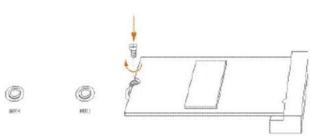
Step 4
Hand tighten the standoff into the desired NUT on the motherboard.
text_image
BET MDT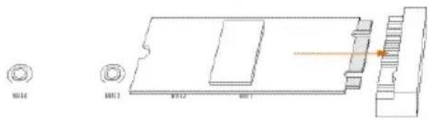
natural_image
Technical line drawing of a mechanical component with mounting holes and a highlighted section (no text or symbols)Step 5
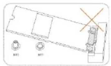
Align and gently insert the M.2 (NGFF) SSD module into the M.2 slot. Please be aware that the M.2 (NGFF) SSD module only fits in one orientation.
text_image
BUT4 HUT1Step 6
Tighten the screw knob to secure the module into place.
M.2\_SSD (NGFF) Module Support List
PCIe Interface SATA Interface
SanDisk SD6PP4M-128G Intel SSDSCKGW080A401/80G
SanDisk SD6PP4M-256G
For the latest updates of M.2_SSD (NFGG) module support list, please visit our website for details: http://www.asrock.com
2.8 ASRock USB 3.1/A+C Installation Guide
Specifications
| Platform | • Size: 3.1-in x 3.2-in, 7.9 cm x 8.1 cm |
| Controller | • ASMedia ASM1142 Controller |
| PCIE | • PCI Express x4 Connector (x2 lane)• Compliant with PCI Express 1.1, 2.0 and 3.0 specifications• Supports data rates up to 10 Gbps• Compliant with x4, x8 or x16 PCI Express Slots |
| Connector | • 1 x USB 3.1 Type-A Port (Supports ESD Protection (ASRock Full Spike Protection))* For charging Type-A USB devices, we suggest using the Type-A connectors on your motherboard.• 1 x USB 3.1 Type-C Port (Supports ESD Protection (ASRock Full Spike Protection))* This port supports power outputs up to 5V/3A. For charging Type-C USB devices, the device should support Type-C standards to adjust the current because it will be different in Power On state (3 Amp) and Sleep state (1 Amp).* Some Type-C USB devices may only be charged by its own adapter. |
| OS | • Microsoft® Windows® 8.1 32-bit / 8.1 64-bit / 8 32-bit / 8 64-bit / 7 32-bit / 7 64-bit |
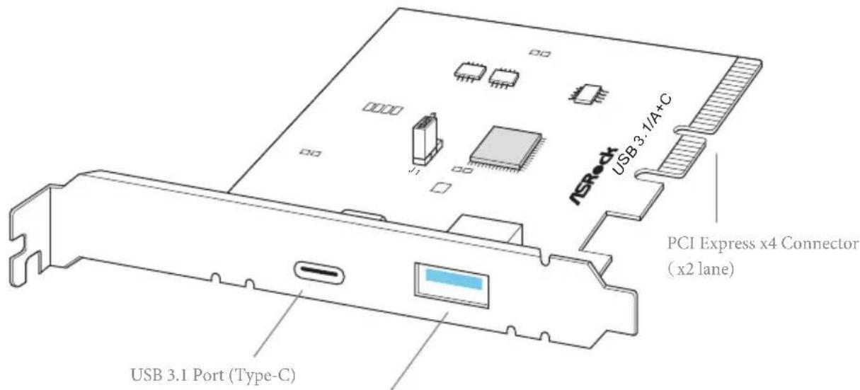
text_image
USB 3.1 A+C NSRock PCI Express x4 Connector (x2 lane) USB 3.1 Port (Type-C)USB 3.1 Port (Type-A)
Installation Procedure
The ASRock USB 3.1/A+C provides two external USB 3.1 ports which support transfer rates up to 10 Gbps. Follow the simple steps below to install the ASRock USB 3.1/A+C.
Step 1
Power off the PC and unplug the power cord. Detach all other cables from the PC.
Step 2
Remove the side panel from the computer case.
*Refer to the documentation that comes with your PC for details.
Step 3
Locate an available x4, x8 or x16 PCI Express slot on your motherboard and remove its slot bracket.
*To maximize the performance of ASRock USB 3.1 /A+C, it is highly recommended to insert the card into the PCIE5 (from NB).
Step 4
Align the ASRock USB 3.1/A+C with the PCI Express slot and press down firmly until it is fully seated in the slot. Then secure the card with the slot bracket's holding screw.
Step 5
Replace the side panel. Reconnect the power cord and any other cables that were disconnected.
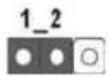
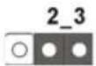
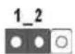
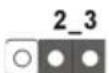
\*Jumper Setup:
Jumper J1 is set to Pin1-2 by default and allows device charging during S3 (Sleep), S4 (Suspend) or S5 (Power Off) power states. To disable device charging during S3/S4/S5 (Power Off) power states, you need to move the jumper cap placed on Pin1-2 (default) to Pin2-3.
*Please install driver for Windows® 7 (32-bit and 64-bit).
1 Einleitung
- FCC, CE, WHQL
- ErP/EuP Ready (alimentation ErP/EuP ready requise)
text_image
Short OpenCavalier Clear CMOS (CLRCMOS1)
(voir p.1, No. 21)
- Microsoft" Windows" 10 a 64-bit/8.1 a 32-bit/8.1 a 64-bit/8 a 32-bit/8 a 64-bit/7 a 32-bit/7 a 64-bit
Certificazioni
- FCC, CE, WHQL
- ErP/EuP Ready (è necessaria alimentazione ErP/EuP ready)

64-bit / 7 32-bit / 7 64-bit
认证
text_image
Short Open清除 CMOS 跳线
(CLRCMOS1)
(见第1页,第21个)
清除 CMOS默认
If you need to contact ASRock or want to know more about ASRock, you're welcome to visit ASRock's website at http://www.asrock.com; or you may contact your dealer for further information. For technical questions, please submit a support request form at http://www.asrock.com/support/tsd.asp
ASRock Incorporation
2F., No.37, Sec. 2, Jhongyang S. Rd., Beitou District,
Taipei City 112, Taiwan (R.O.C.)
ASRock EUROPE B.V.
Bijsterhuizen 3151
6604 LV Wijchen
The Netherlands
Phone: +31-24-345-44-33
Fax: +31-24-345-44-38
ASRock America, Inc.
13848 Magnolia Ave, Chino, CA91710
U.S.A.
Phone: +1-909-590-8308
Fax: +1-909-590-1026