USER MANUAL A88M-G/3.1 ASROCK
Published December 2015
Copyright©2015 ASRock INC. All rights reserved.
Copyright Notice:
No part of this documentation may be reproduced, transcribed, transmitted, or translated in any language, in any form or by any means, except duplication of documentation by the purchaser for backup purpose, without written consent of ASRock Inc.
Products and corporate names appearing in this documentation may or may not be registered trademarks or copyrights of their respective companies, and are used only for identification or explanation and to the owners' benefit, without intent to infringe.
Disclaimer:
Specifications and information contained in this documentation are furnished for informational use only and subject to change without notice, and should not be constructed as a commitment by ASRock. ASRock assumes no responsibility for any errors or omissions that may appear in this documentation.
With respect to the contents of this documentation, ASRock does not provide warranty of any kind, either expressed or implied, including but not limited to the implied warranties or conditions of merchantability or fitness for a particular purpose.
In no event shall ASRock, its directors, officers, employees, or agents be liable for any indirect, special, incidental, or consequential damages (including damages for loss of profits, loss of business, loss of data, interruption of business and the like), even if ASRock has been advised of the possibility of such damages arising from any defect or error in the documentation or product.

This device complies with Part 15 of the FCC Rules. Operation is subject to the following two conditions:
(1) this device may not cause harmful interference, and
(2) this device must accept any interference received, including interference that may cause undesired operation.
CALIFORNIA, USA ONLY
The Lithium battery adopted on this motherboard contains Perchlorate, a toxic substance controlled in Perchlorate Best Management Practices (BMP) regulations passed by the California Legislature. When you discard the Lithium battery in California, USA, please follow the related regulations in advance.
"Perchlorate Material-special handling may apply, see www.dtsc.ca.gov/hazardouswaste/perchlorate"
ASRock Website: http://www.asrock.com

The terms HDMI ^™ and HDMI High-Definition Multimedia Interface, and the HDMI logo are trademarks or registered trademarks of HDMI Licensing LLC in the United States and other countries.

Motherboard Layout
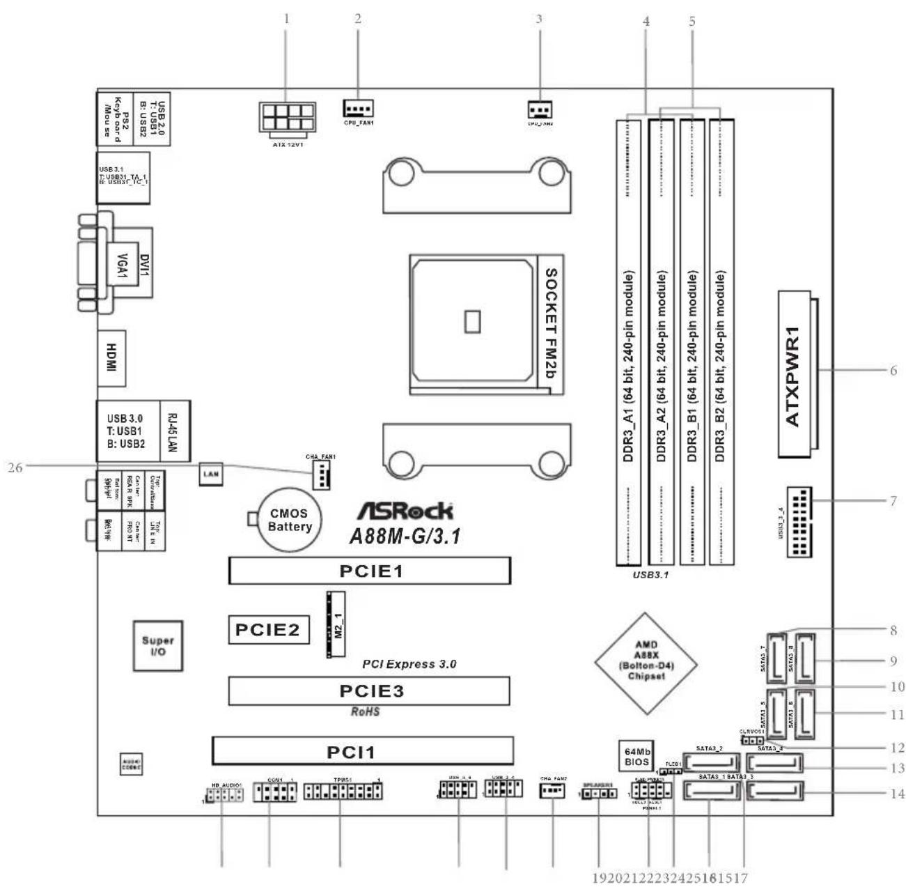
No. Description
1 ATX 12V Power Connector (ATX12V1)
2 CPU Fan Connector (CPU_FAN1)
3 CPU Fan Connector (CPU_FAN2)
4 2 x 240-pin DDR3 DIMM Slots (DDR3_A1, DDR3_B1)
5 2 x 240-pin DDR3 DIMM Slots (DDR3_A2, DDR3_B2)
6 ATX Power Connector (ATXPWR1)
7 USB 3.0 Header (USB3_3_4)
8 SATA3 Connector (SATA3_7)
9 SATA3 Connector (SATA3_8)
10 SATA3 Connector (SATA3_5)
11 SATA3 Connector (SATA3_6)
12 Clear CMOS Jumper (CLRCMOS1)
13 SATA3 Connector (SATA3_4)
14 SATA3 Connector (SATA3_3)
15 SATA3 Connector (SATA3_2)
16 SATA3 Connector (SATA3_1)
17 Power LED Header (PLED1)
18 System Panel Header (PANEL1)
19 Chassis Speaker Header (SPEAKER1)
20 Chassis Fan Connector (CHA_FAN2)
21 USB 2.0 Header (USB_3_4)
22 USB 2.0 Header (USB_5_6)
23 TPM Header (TPMS1)
24 COM Port Header (COM1)
25 Front Panel Audio Header (HD_AUDIO1)
26 Chassis Fan Connector (CHA_FAN1)
I/O Panel
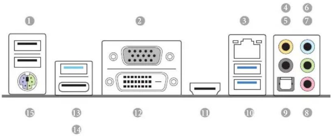
No. Description No. Description
1 USB 2.0 Ports (USB_1_2) 9 Optical SPDIF Out Port
2 D-Sub Port (VGA1) 10 USB 3.0 Ports (USB3_1_2)
3 LAN RJ-45 Port* 11 HDMI Port
4 Central / Bass (Orange) 12 DVI-D Port (DVI1)
5 Rear Speaker (Black) 13 USB 3.1 Type-A Port (USB31_TA_1)
6 Line In (Light Blue) 14 USB 3.1 Type-C Port (USB31_TC_1)
7 Front Speaker (Lime)*** 15 PS/2 Mouse/Keyboard Port
8 Microphone (Pink)
* It is recommended to install the USB Keyboard/Mouse cable to USB 2.0 ports (USB_1_2) instead of USB 3.0 ports.
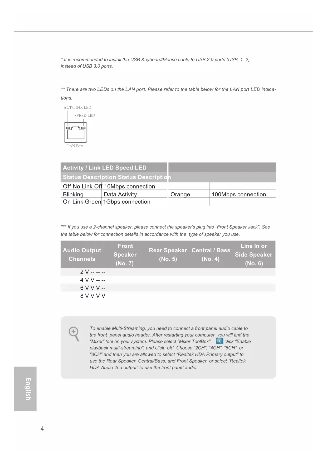
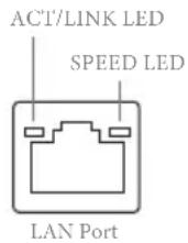
** There are two LEDs on the LAN port. Please refer to the table below for the LAN port LED indications.
| Activity / Link LED Speed LED | |
| Status Description Status Description |
| Off No Link Off | 10Mbps connection | | |
| Blinking | Data Activity | Orange | 100Mbps connection |
| On Link Green | 1Gbps connection | | |
*** If you use a 2-channel speaker, please connect the speaker's plug into "Front Speaker Jack". See the table below for connection details in accordance with the type of speaker you use.
| Audio Output Channels | Front Speaker (No. 7) | Rear Speaker (No. 5) | Central / Bass (No. 4) | Line In or Side Speaker (No. 6) |
| 2 V -- -- -- | | | | |
| 4 V V -- -- | | | | |
| 6 V V V -- | | | | |
| 8 V V V V | | | | |

To enable Multi-Streaming, you need to connect a front panel audio cable to the front panel audio header. After restarting your computer, you will find the "Mixer" tool on your system. Please select "Mixer ToolBox" click "Enable playback multi-streaming", and click "ok". Choose "2CH", "4CH", "6CH", or "8CH" and then you are allowed to select "Realtek HDA Primary output" to use the Rear Speaker, Central/Bass, and Front Speaker, or select "Realtek HDA Audio 2nd output" to use the front panel audio.
1. Introduction
Thank you for purchasing ASRock A88M-G/3.1 motherboard, a reliable motherboard produced under ASRock's consistently stringent quality control. It delivers excellent performance with robust design conforming to ASRock's commitment to quality and endurance.
This Quick Installation Guide contains introduction of the motherboard and step-by-step installation guide. More detailed information of the motherboard can be found in the user manual presented in the Support CD.
Because the motherboard specifications and the BIOS software might be updated, the content of this manual will be subject to change without notice. In case any modifications of this manual occur, the updated version will be available on ASRock website without further notice. You may find the latest VGA cards and CPU support lists on ASRock website as well. ASRock website http://www.asrock.com
If you require technical support related to this motherboard, please visit our website for specific information about the model you are using. www.asrock.com/support/index.asp
1.1 Package Contents
ASRock A88M-G/3.1 Motherboard (Micro ATX Form Factor)
ASRock A88M-G/3.1 Quick Installation Guide
ASRock A88M-G/3.1 Support CD
2 x Serial ATA (SATA) Data Cables (Optional)
1 x I/O Panel Shield
1 x Screw for M.2 Socket
1.2 Specifications
| Platform | • Micro ATX Form Factor• Solid Capacitor design |
| CPU | • Supports Socket FM2+ 95W / FM2 100W processors• 4 + 2 Power Phase design |
| Chipset | • AMD A88X (Bolton-D4) |
| Memory | • Dual Channel DDR3 Memory Technology• 4 x DDR3 DIMM Slots• Supports DDR3 2400+(OC)/2133/1866/1600/1333/1066 non-ECC, un-buffered memory (see CAUTION 1)• Max. capacity of system memory: 64GB (see CAUTION 2)• Supports Intel® Extreme Memory Profile (XMP) 1.3 / 1.2• Supports AMD Memory Profile (AMP) up to AMP 2400 |
| Expansion Slot | • 1 x PCI Express 3.0 x16 Slot (PCIE1 @ x16 mode)* PCIE 3.0 is only supported with FM2+ CPU. With FM2 CPU, it only supports PCIE 2.0.• 1 x PCI Express 2.0 x16 Slot (PCIE3 @ x4 mode)• 1 x PCI Express 2.0 x1 Slot• 1 x PCI Slot• Supports AMD Quad CrossFireXTM, CrossFireXTM and Dual Graphics |
| Graphics | • Integrated AMD RadeonTM R7/R5 Series Graphics in A-series APU• DirectX 11.1, Pixel Shader 5.0 with FM2+ CPU. DirectX 11, Pixel Shader 5.0 with FM2 CPU.• Max. shared memory 2GB• Three graphics output options: D-Sub, DVI-D and HDMI• Supports Triple Monitor• Supports HDMI with max. resolution up to 4K × 2K (4096x2160) @ 24Hz* Only FM2+ APU can support up to 4096x2160 resolution display via HDMI port• Supports Dual-link DVI-D with max. resolution up to 2560x1600 @ 60Hz |
• Supports D-Sub with max. resolution up to 1920x1200 @ 60Hz
- Supports Auto Lip Sync, Deep Color (12bpc), xvYCC and HBR (High Bit Rate Audio) with HDMI Port (Compliant HDMI monitor is required)
• Supports Blu-ray Stereoscopic 3D with HDMI Port
- Supports AMD Steady Video™ 2.0: New video post processing capability for automatic jitter reduction on home/online video
• Supports HDCP with DVI-D and HDMI Ports
• Supports Full HD 1080p Blu-ray (BD) playback with DVI-D and HDMI Ports
Audio
• 7.1 CH HD Audio with Content Protection (Realtek ALC1150 Audio Codec)
• Premium Blu-ray Audio support
• Supports Surge Protection (ASRock Full Spike Protection)
• ELNA Audio Caps
LAN
• PCIE x1 Gigabit LAN 10/100/1000 Mb/s
• Realtek RTL8111GR
• Supports Wake-On-WAN
• Supports Wake-On-LAN
• Supports Lightning/ESD Protection (ASRock Full Spike Protection)
• Supports LAN Cable Detection
• Supports Energy Efficient Ethernet 802.3az
- Supports PXE
Rear
• 1 x PS/2 Mouse/Keyboard Port
- 1 x D-Sub Port
• 1 x DVI-D Port
• 1 x HDMI Port
- 1 x USB 3.1 Type-A Port (10 Gb/s) (ASMedia ASM1143) (Supports ESD Protection (ASRock Full Spike Protection))
- 1 x USB 3.1 Type-C Port (10 Gb/s) (ASMedia ASM1143) (Supports ESD Protection (ASRock Full Spike Protection))
- 2 x USB 3.0 Ports (AMD A88X (Bolton-D4)) (Supports ESD Protection (ASRock Full Spike Protection))
- 2 x USB 2.0 Ports (Supports ESD Protection (ASRock Full Spike Protection))
- 1 x RJ-45 LAN Port with LED (ACT/LINK LED and SPEED LED)
• HD Audio Jacks: Rear Speaker / Central / Bass / Line in / Front Speaker / Microphone
Storage
- 8 x SATA3 6.0 Gb/s Connectors, support RAID (RAID 0, RAID 1, RAID 5 and RAID 10), NCQ, AHCI and Hot Plug
- 1 x M.2_SSD (NGFF) Socket 3, supports type 2230/2242/2260/2280 M.2 PCI Express module up to Gen2 x4 (20 Gb/s)
* If PCIE3 is occupied, M2_1 will be disabled.
* Supports ASRock U.2 Kit
Connec-
tor
• 1 x COM Port Headerr
- 1 x TPM Header
• 2 x CPU Fan Connectors (1 x 4-pin, 1 x 3-pin)
• 2 x Chassis Fan Connectors (2 x 4-pin)
• 1 x 24 pin ATX Power Connector
• 1 x 8 pin 12V Power Connector
• 1 x Front Panel Audio Connector
• 2 x USB 2.0 Headers (Support 4 USB 2.0 ports)
(Supports ESD Protection (ASRock Full Spike Protection))
• 1 x USB 3.0 Header by AMD A88X (Bolton-D4)
(Supports 2 USB 3.0 ports) (Supports ESD Protection (ASRock Full Spike Protection))
BIOS
Feature
• 64Mb AMI UEFI Legal BIOS with GUI support
• Supports "Plug and Play"
• ACPI 1.1 Compliant wake up events
• Supports jumperfree
• SMBIOS 2.3.1 support
• DRAM, CPU Voltage multi-adjustment
Hardware Monitor
• CPU/Chassis temperature sensing
• CPU/Chassis Tachometer
• CPU/Chassis Quiet Fan
• CPU/Chassis Fan multi-speed control
• Voltage monitoring: +12V, +5V, +3.3V, Vcore
OS
- Microsoft Windows ^® 10 32-bit / 10 64-bit / 8.1 32-bit / 8.1 64-bit / 7 32-bit / 7 64-bit
* For the updated Windows ^® 10 driver, please visit
ASRock's website for details: http://www.asrock.com
* Carrizo FM2r2 processor supports Windows ^ 10 64-bit/8.1 64-bit / 7 32-bit / 7 64-bit only.
Certifications
- FCC, CE, WHQL
- ErP/EuP Ready (ErP/EuP ready power supply is required)
* For detailed product information, please visit our website: http://www.asrock.com
WARNING
Please realize that there is a certain risk involved with overclocking, including adjusting the setting in the BIOS, applying Untied Overclocking Technology, or using third-party overclocking tools. Overclocking may affect your system's stability, or even cause damage to the components and devices of your system. It should be done at your own risk and expense. We are not responsible for possible damage caused by overclocking.
CAUTION!
- Whether 2400/2133/1866/1600MHz memory speed is supported depends on the CPU you adopt. If you want to adopt DDR3 2400/2133/1866/1600 memory module on this motherboard, please refer to the memory support list on our website for the compatible memory modules.
ASRock website http://www.asrock.com
- Due to the operating system limitation, the actual memory size may be less than 4GB for the reservation for system usage under Windows ^® 10 / 8.1 / 7. For Windows ^® 64-bit OS with 64-bit CPU, there is no such limitation.
2. Installation
This is an Micro ATX form factor motherboard. Before you install the motherboard, study the configuration of your chassis to ensure that the motherboard fits into it.
Pre-installation Precautions
Take note of the following precautions before you install motherboard components or change any motherboard settings.
Before you install or remove any component, ensure that the power is switched off or the power cord is detached from the power supply. Failure to do so may cause severe damage to the motherboard, peripherals, and/or components.
- Unplug the power cord from the wall socket before touching any component.
- To avoid damaging the motherboard components due to static electricity, NEVER place your motherboard directly on the carpet or the like. Also remember to use a grounded wrist strap or touch a safety grounded object before you handle components.
- Hold components by the edges and do not touch the ICs.
- Whenever you uninstall any component, place it on a grounded anti-static pad or in the bag that comes with the component.
- When placing screws into the screw holes to secure the motherboard to the chassis, please do not over-tighten the screws! Doing so may damage the motherboard.
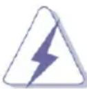
2.1 CPU Installation
Step 1. Unlock the socket by lifting the lever up to a 90 °angle.
natural_image
Diagram of a square electronic component with a vertical pole and a curved arrow indicating rotation (no text or symbols)
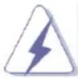
Step 2. Position the CPU directly above the socket such that the CPU corner with the golden triangle matches the socket corner with a small triangle.
Step 3. Carefully insert the CPU into the socket until it fits in place.
natural_image
Technical line drawing of a square mechanical component with a protruding rod and a highlighted circular feature (no text or symbols)

The CPU fits only in one correct orientation. DO NOT force the CPU into the socket to avoid bending of the pins.
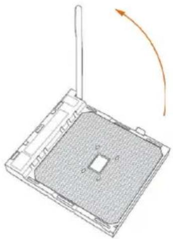
Step 4. When the CPU is in place, press it firmly on the socket while you push down the socket lever to secure the CPU. The lever clicks on the side tab to indicate that it is locked.
natural_image
Technical line drawing of a mechanical component with an arrow indicating rotation (no text or symbols)
2.2 Installation of CPU Fan and Heatsink
After you install the CPU into this motherboard, it is necessary to install a larger heatsink and cooling fan to dissipate heat. You also need to spray thermal grease between the CPU and the heatsink to improve heat dissipation. Make sure that the CPU and the heatsink are securely fastened and in good contact with each other. Then connect the CPU fan to the CPU FAN connector (CPU_FAN1 and CPU_FAN2, see Page 1, No. 2, 3). For proper installation, please kindly refer to the instruction manuals of the CPU fan and the heatsink.
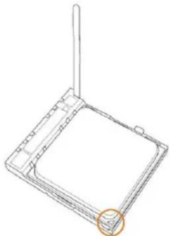
2.3 Installation of Memory Modules (DIMM)
This motherboard provides four 240-pin DDR3 (Double Data Rate 3) DIMM slots, and supports Dual Channel Memory Technology.

- For dual channel configuration, you always need to install identical (the same brand, speed, size and chip-type) DDR3 DIMM pairs.
- It is unable to activate Dual Channel Memory Technology with only one or three memory module installed.
- It is not allowed to install a DDR or DDR2 memory module into a DDR3 slot; otherwise, this motherboard and DIMM may be damaged.
- If you adopt DDR3 2600/2400/2133/1866/1600 memory modules on this motherboard, it is recommended to install them on DDR3_A2 and DDR3_B2 slots.
Dual Channel Memory Configuration
| Priority | DDR3_A1 | DDR3_A2 | DDR3_B1 | DDR3_B2 |
| 1 Populated Populated | | | |
| 2 Populated Populated | | | |
| 3 Populated Populated | Populated Populated | |

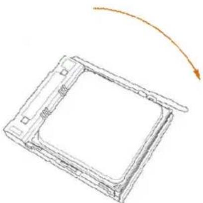
The DIMM only fits in one correct orientation. It will cause permanent damage to the motherboard and the DIMM if you force the DIMM into the slot at incorrect orientation.
1
natural_image
Technical line drawing of a mechanical support structure with rotational arrows indicating motion (no text or symbols)
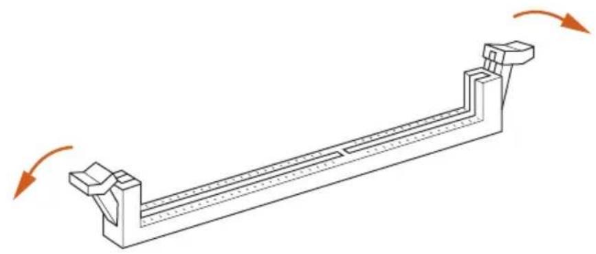
2
natural_image
Illustration of hands assembling a mechanical component with a highlighted section (no text or symbols)
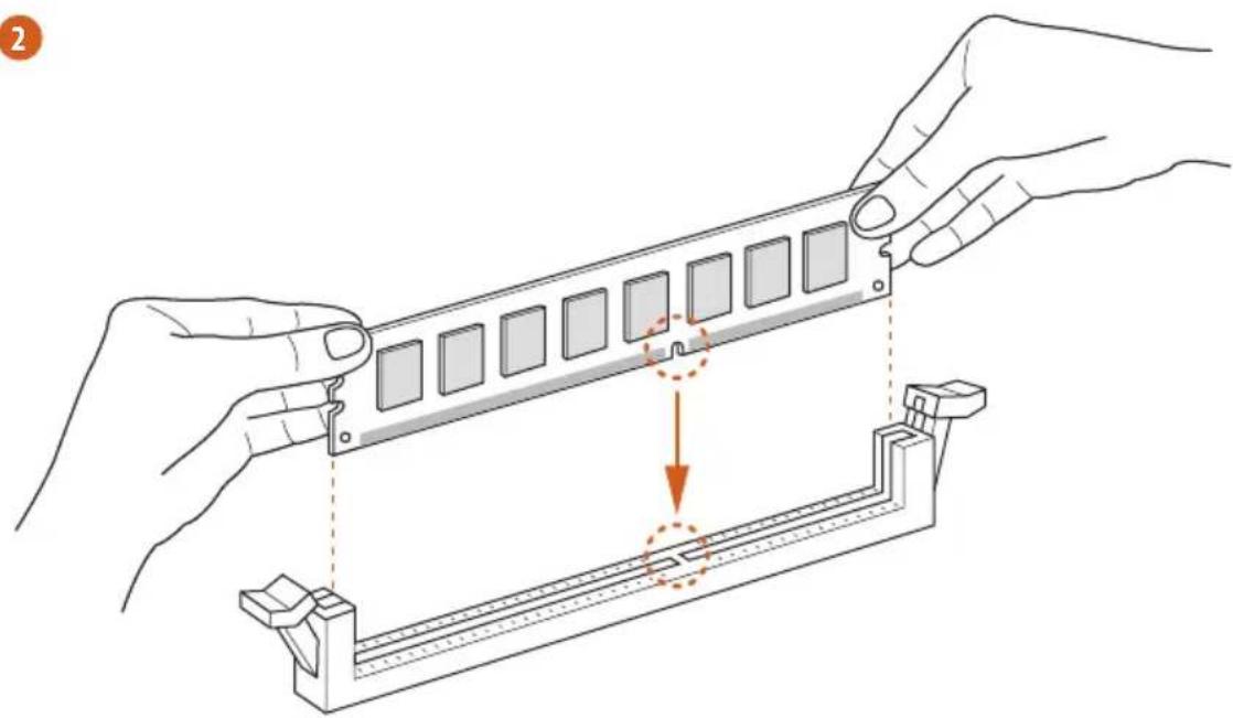
3
natural_image
Isometric line drawing of a rectangular mechanical component with multiple square cutouts and directional arrows indicating rotation (no text or symbols)
2.4 Expansion Slots (PCI and PCI Express Slots)
There are 1 PCI slot and 3 PCI Express slots on this motherboard.

Before installing an expansion card, please make sure that the power supply is switched off or the power cord is unplugged. Please read the documentation of the expansion card and make necessary hardware settings for the card before you start the installation.
PCI Slots: PCI slots are used to install expansion cards that have the 32-bit PCI interface.
PCIE Slots:
PCIE2 (PCIe 2.0 x1 slot) is used for PCI Express cards with x1 lane width cards.
PCIE1 (PCIe 3.0 x16 slot) is used for PCI Express x16 lane width graphics cards.
PCIE3 (PCIe 2.0 x16 slot) is used for PCI Express x4 lane width graphics cards.
PCIe Slot Configurations
PCIE1 PCIE3
Single Graphics Card x16 N/A
Two Graphics Cards in CrossFireX™ Mode
x16 x4

For a better thermal environment, please connect a chassis fan to the motherboard's chassis fan connector (CHA_FAN1 or CHA_FAN2) when using multiple graphics cards.
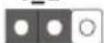
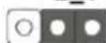
2.5 Jumpers Setup
The illustration shows how jumpers are setup. When the jumper cap is placed on pins, the jumper is "Short". If no jumper cap is placed on pins, the jumper is "Open". The illustration shows a 3-pin jumper whose pin1 and pin2 are "Short" when jumper cap is placed on these 2 pins.
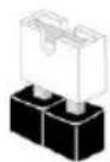
Short
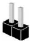
Open
Jumper
Setting
Description
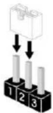
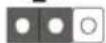
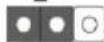
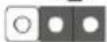
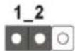
Clear CMOS Jumper
(CLRCMOS1)
(see p.1, No. 12)
1_2
2 3
Clear CMOSDefault
Note: CLRCMOS1 allows you to clear the data in CMOS. To clear and reset the system parameters to default setup, please turn off the computer and unplug the power cord from the power supply. After waiting for 15 seconds, use a jumper cap to short pin2 and pin3 on CLRCMOS1 for 5 seconds. However, please do not clear the CMOS right after you update the BIOS. If you need to clear the CMOS when you just finish updating the BIOS, you must boot up the system first, and then shut it down before you do the clear-CMOS action. Please be noted that the password, date, time, user default profile, 1394 GUID and MAC address will be cleared only if the CMOS battery is removed.
If you clear the CMOS, the case open may be detected. Please adjust the BIOS option "Clear Status" to clear the record of previous chassis intrusion status.
2.6 Onboard Headers and Connectors
Onboard headers and connectors are NOT jumpers. Do NOT place jumper caps over these headers and connectors. Placing jumper caps over the headers and connectors will cause permanent damage of the motherboard!
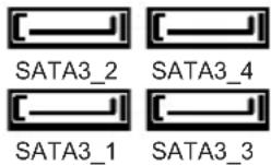
Serial ATA3 Connectors These eight Serial ATA3
(SATA3_1: see p.1, No. 16) (SATA3) connectors support
(SATA3_2: see p.1, No. 15) SATA data cables for internal
(SATA3_3: see p.1, No. 14) storage devices. The current
(SATA3_4: see p.1, No. 13) SATA3 interface allows up to
(SATA3_5: see p.1, No. 10) 6.0 Gb/s data transfer rate.
(SATA3_6: see p.1, No. 11)
(SATA3_7: see p.1, No. 8) SATA3_2 SATA3_4
(SATA3_8: see p.1, No. 9)
USB 2.0 Headers Besides two default USB 2.0
(9-pin USB_3_4) ports on the I/O panel, there
(see p.1 No. 21) are two USB 2.0 headers on
(9-pin USB_5_6) this motherboard. Each USB 2.0
(see p.1 No. 22) header can support two USB
2.0 ports.
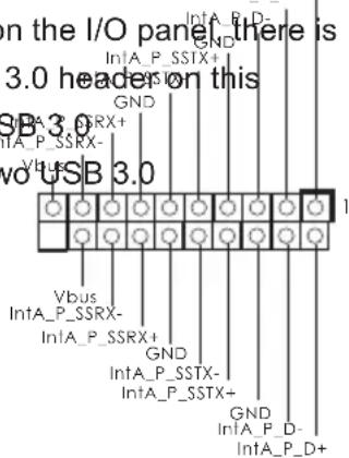
USB 3.0 Header Besides two default USB 3.0
(19-pin USB3_3_4) ports on the I/O panel there is
(see p.1 No. 7) one USB 3.0 headers on this
motherboard. This USB 3.0
header can support two USB 3.0
ports.
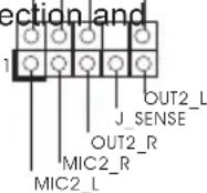
Front Panel Audio Header This is an interface for the front
(9-pin HD_AUDIO1) panel audio cable that allows OUT_RET
(see p.1 No. 25) convenient connec control of audio devices.

-
High Definition Audio supports Jack Sensing, but the panel wire on the chassis must support HDA to function correctly. Please follow the instruction in our manual and chassis manual to install your system.
-
If you use AC'97 audio panel, please install it to the front panel audio header as below:
A. Connect Mic_IN (MIC) to MIC2_L.
B. Connect Audio_R (RIN) to OUT2_R and Audio_L (LIN) to OUT2_L.
C. Connect Ground (GND) to Ground (GND).
D. MIC_RET and OUT_RET are for HD audio panel only. You don't need to connect them for AC'97 audio panel.
E. To activate the front mic.
For Windows ^ 10 / 10 64-bit / 8.1 / 8.1 64-bit / 7 / 7 64-bit OS: Go to the "FrontMic" Tab in the Realtek Control panel. Adjust "Recording Volume".
System Panel Header This header accommodates
(9-pin PANEL1) several system front panel
(see p.1 No. 18)
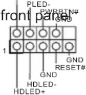
functions.

Connect the power switch, reset switch and system status indicator on the chassis to this header according to the pin assignments below. Note the positive and negative pins before connecting the cables.
PWRBTN (Power Switch):
Connect to the power switch on the chassis front panel. You may configure the way to turn off your system using the power switch.
RESET (Reset Switch):
Connect to the reset switch on the chassis front panel. Press the reset switch to restart the computer if the computer freezes and fails to perform a normal restart.
PLED (System Power LED):
Connect to the power status indicator on the chassis front panel. The LED is on when the system is operating. The LED keeps blinking when the sys-tem is in S3 sleep state. The LED is off when the system is in S4 sleep state or powered off (S5).
HDLED (Hard Drive Activity LED):
Connect to the hard drive activity LED on the chassis front panel. The LED is on when the hard drive is reading or writing data.
The front panel design may differ by chassis. A front panel module mainly consists of power switch, reset switch, power LED, hard drive activity LED, speaker and etc. When connecting your chassis front panel module to this header, make sure the wire assignments and the pin assign-ments are matched correctly.
Chassis Speaker Header Please connect the chassis DUMMY SPEAKER
(4-pin SPEAKER 1) speaker to this reader.
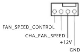
Chassis Fan Connectors Please connect the fan cable
(4-pin CHA_FAN1) to the fan connector and
(see p.1 No. 26) match the black wire to the GND
ground pin.
(4-pin CHA_FAN2)
(see p.1 No. 20)
CPU Fan Connector Please connect the CPU fan
(4-pin CPU_FAN1) cable to the connector and
(see p.1 No. 2) match the black wire to the
ground pin.
(3-pin CPU_FAN2)
(see p.1, No. 3)
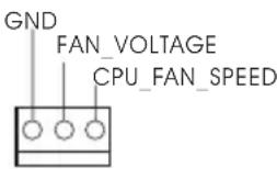

Though this motherboard provides 4-Pin CPU fan (Quiet Fan) support, the 3-Pin CPU fan still can work successfully even without the fan speed control function. If you plan to connect the 3-Pin CPU fan to the CPU fan connector on this motherboard, please connect it to Pin 1-3.
Pin 1-3 Connected

3-Pin Fan Installation
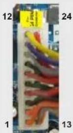
ATX Power Connector Please connect an ATX power
(24-pin ATXPWR1) supply to this connector.
(see p.1 No. 6)
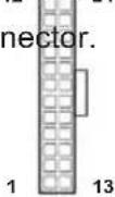

Though this motherboard provides 24-pin ATX power connector, it can still work if you adopt a traditional 20-pin ATX power supply.
To use the 20-pin ATX power supply, please plug your power supply along with Pin 1 and Pin 13.
20-Pin ATX Power Supply Installation
natural_image
Close-up of a multicolored electronic component with visible wires and connectors (no text or symbols)
ATX 12V Power Connector Please connect an ATX 12V
(8-pin ATX12V1) power supply to this connector.
(see p.1 No. 1)
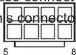

Though this motherboard provides 8-pin ATX 12V power connector, it can still work
if you adopt a traditional 4-pin ATX 12V power supply. To use the 4-pin ATX power supply, please plug your power supply along with Pin 1 and Pin 5.
4-Pin ATX 12V Power Supply Installation
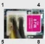
Serial port Header This COM1 header supports a
(9-pin COM1)
(see p.1 No. 24)
serial port module.
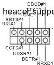
TPM Header
(17-pin TPMS1)
(see p.1, No. 23)
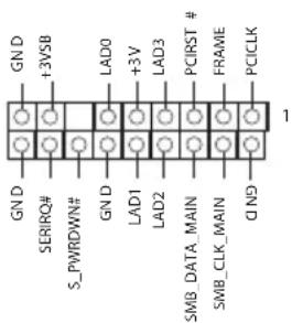
This connector supports Trusted Platform Module (TPM) system, which can securely store keys, digital certificates, passwords, and data. A TPM system also helps enhance network security, protects digital identities, and ensures platform integrity.
2.7 M.2\_SSD (NGFF) Module Installation Guide
The M.2, also known as the Next Generation Form Factor (NGFF), is a small size and versatile card edge connector that aims to replace mPCIe and mSATA. The M.2 Socket (M2_1) support M.2 PCI Express module up to Gen2 x4 (20Gb/s).
* If PCIE3 is occupied, M2_1 will be disabled.
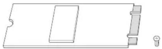
Installing the M.2\_SSD (NGFF) Module
natural_image
Pure technical line drawing of a rectangular component with a slot and two screws, no text or symbols present.
Step 1
Prepare a M.2_SSD (NGFF) module and the screw.
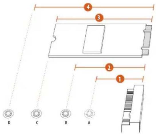
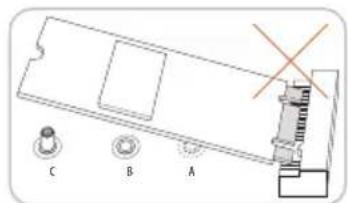
Step 2
Depending on the PCB type and length of your M.2_SSD (NGFF) module, find the corresponding nut location to be used.
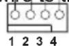
No.1234
Nut Location A B C D
Move the standoff based on the module type and length.
The standoff is placed at the nut location D by default. Skip Step 3 and 4 and go straight to Step 5 if you are going to use the default nut.
Otherwise, release the standoff by hand.


Step 4
Peel off the yellow protective film on the nut to be used.
Hand tighten the standoff into the desired nut location on the motherboard.
natural_image
Technical diagram of a mechanical assembly with labeled components A, B, C, D and an orange arrow indicating direction (no text or symbols beyond labels)
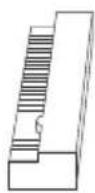
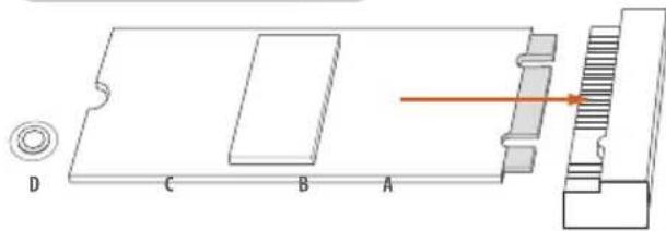
Step 5
Align and gently insert the M.2 (NGFF) SSD module into the M.2 slot. Please be aware that the M.2 (NGFF) SSD module only fits in one orientation.
natural_image
Pure mechanical diagram showing a lever and pulley system without any text, numbers, or symbols
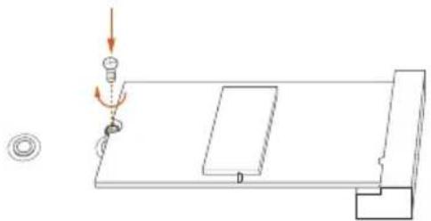
Step 6
Tighten the screw with a screwdriver to secure the module into place. Please do not overtighten the screw as this might damage the module.
M.2\_SSD (NGFF) Module Support List
| VendorSizeInterfaceLengthP/N |
| Kingston | 480GB | PCIe2 x4 | 2280 | SH2280S3/480G |
| Plextor | 256GB | PCIe | 2280 | PX-G256M6e |
| Plextor | 512GB | PCIe | 2280 | PX-G512M6e |
| Samsung | 256GB | PCIe3 x4* | 2280 | SM951 (MZHPV256HDGL) |
| Samsung | 512GB | PCIe3 x4* | 2280 | SM951 (MZHPV512HDGL) |
| Samsung | 512GB | PCIe x4 | 2280 | XP941-512G (MZHPU512HCGL) |
| SanDisk | 128GB | PCIe | 2260 | SD6PP4M-128G |
| SanDisk | 256GB | PCIe | 2260 | SD6PP4M-256G |
*Please note that the M.2 Socket on this motherboard supports M.2 PCI Express module up to Gen2 x4 (20Gb/s).
For the latest updates of M.2_SSD (NFGG) module support list, please visit our website for details: http://www.asrock.com
1. Einführung
www.asrock.com/support/index.asp
1.1 Kartoninhalt
ASRock A88M-G/3.1 Motherboard (Micro ATX-Formfaktor)
ASRock A88M-G/3.1 Support-CD
Zwei Serial ATA (SATA) -Datenkabel (optional)
Ein I/O Shield
(CLRCMOS1, 3-Pin jumper)
(siehe S.1, No. 12)
Einstellun
1 2
Default-
Einstellung
Beschreibung
2 3
CMOS
löschen
Seriell-ATA3-Anschlüsse
natural_image
Close-up of a colorful electrical connector or socket with numbered labels (1, 12, 24, 13) and no visible text or symbols on the socket itself.
natural_image
Close-up of a circuit board with multicolored wires and connectors, labeled 1, 12, 24, 13 (no readable text or symbols beyond labels)
www.asrock.com/support/index.asp
natural_image
Close-up of a circuit board with multicolored wires and connectors, labeled 1, 12, 24, and 13 (no readable text or symbols beyond labels)
www.asrock.com/support/index.asp
(CLRCMOS1, jumper de 3 pins)
(ver p.1, No. 12)
1_2
Valor predeterminado
2 3
Restablecimiento de
la CMOS
natural_image
Close-up of a circuit board with multicolored wires and connectors (no visible text or symbols)
www.asrock.com/support/index.asp
(CLRCMOS1, jumper de 3 pinos)
(CLRCMOS1, 3-pinli jumper)
(bkz. s.1 No. 12)
Clear CMOSDefault
SATA3 arayuzü 6,0 Gb/sn veri
natural_image
Close-up of a colorful electrical connector with numbered pins (1, 12, 24, 13) and no visible text or symbols on the main body.
natural_image
Close-up of a computer interface with multicolored cable connectors (no visible text or symbols)
www.asrock.com/support/index.asp
1.1 包装盒内物品
www.asrock.com/support/index.asp
1.1 自装盒队物品
If you need to contact ASRock or want to know more about ASRock, you're welcome to visit ASRock's website at http://www.asrock.com; or you may contact your dealer for further information. For technical questions, please submit a support request form at http://www.asrock.com/support/tsd.asp
ASRock Incorporation
2F., No.37, Sec. 2, Jhongyang S. Rd., Beitou District,
Taipei City 112, Taiwan (R.O.C.)
ASRock EUROPE B.V.
Bijsterhuizen 3151
6604 LV Wijchen
The Netherlands
Phone: +31-24-345-44-33
Fax: +31-24-345-44-38
ASRock America, Inc.
13848 Magnolia Ave, Chino, CA91710
U.S.A.
Phone: +1-909-590-8308
Fax: +1-909-590-1026