
NIG85M30AB - Cooker AEG - Free user manual and instructions
Find the device manual for free NIG85M30AB AEG in PDF.
| Product type | Built-in induction hob |
| Brand | AEG |
| Model | NIG85M30AB |
| Number of cooking zones | 5 |
| Heating technology | Induction |
| Dimensions (W x D) | 800 x 520 mm |
| Installation height | 75 mm |
| Electrical supply | 220-240 V / 400 V 2N, 50 Hz |
| Total power | 7.35 kW |
| Power per zone (max / Boost) | 2300 W / 3200 W (10 min) |
| Cooking zones diameter | 125-210 mm |
| Automatic cooking functions | Stir-fry, Cooking, Melt, Dishes |
| Additional functions | Boost, Bridge, Pause, Child Lock, Hob²Hood |
| Display | Touchscreen with navigation |
| Residual heat indicator | OptiHeat (3 levels) |
| Pan detection | Yes |
| Automatic shut-off | Yes, according to cooking level |
| Power manager | Yes, distribution between zones |
| Cooking surface | Ceramic glass |
| Cleaning | Damp cloth, non-abrasive detergent, scraper for residues |
| Power cable supplied | Yes, type H05V2V2-F |
| Energy consumption (EC) | 182.9 Wh/kg |
Frequently Asked Questions - NIG85M30AB AEG
User questions about NIG85M30AB AEG
0 question about this device. Answer the ones you know or ask your own.
Ask a new question about this device
Download the instructions for your Cooker in PDF format for free! Find your manual NIG85M30AB - AEG and take your electronic device back in hand. On this page are published all the documents necessary for the use of your device. NIG85M30AB by AEG.
USER MANUAL NIG85M30AB AEG
natural_image
Simple geometric diagram of four circles arranged in a 2x2 grid within a square frame (no text or symbols)NIG85M30AB
text_image
QR code with a document icon in the center, likely linking to a digital resource or webpage.PËR REZULTATE PERFEKTE
How to install your AEG Induction Hob - Worktop installation

4. PËRSHKRIM I PRODUKTIT
flowchart
graph TD
    A["①"] --> B["Square"]
    C["1"] --> D["Square"]
    E["2"] --> F["Square"]
    G["3"] --> H["Square"]
    I["4"] --> J["Square"]
    K["67"] --> L["Square"]
    M["8"] --> N["Square"]
    O["≡"] --> P["Square"]
    Q["Y"] --> R["Square"]
    S["1"] --> T["Square"]
    U["2"] --> V["Square"]
    W["3"] --> X["Square"]
    Y["4"] --> Z["Square"]
Simboli Përshkrimi
1 ①
natural_image
Two technical diagrams showing a vertical panel with circular components and a horizontal oval component, both without any text or symbols.
text_image
Two warning symbols: a cross symbol with a circular arrow inside a rectangular frame and an exclamation mark, both pointing to a triangle below.natural_image
Diagram of a balance scale with an arrow indicating the pointer (no text or symbols present)text_image
Diagram showing a ruler measuring a surface with a cross mark symbol, likely illustrating a measurement or calibration concept.text_image
Diagram showing a ruler measuring a rectangular object with a checkmark indicating the measurement.6.15 FUNKSIONET: Zierja
natural_image
Pure diagram of Y-shaped structures with bidirectional arrows, no text or symbols presentnatural_image
Diagram of a smart air lift with a tank and signal icon (no text or symbols)How to install your AEG Induction Hob - Worktop installation

4. ОПИСАНИЕ НА УРЕДА
flowchart
graph TD
    A["①"] --> B["Square"]
    C["1"] --> D["Square"]
    E["2"] --> F["Square"]
    G["3"] --> H["Square"]
    I["4"] --> J["Square"]
    K["678"] --> L["Square"]
    M["≡"] --> N["Square"]
    O["Y"] --> P["Square"]
    Q["●"] --> R["Square"]
    S["●"] --> T["Square"]
flowchart
graph TD
    A["Screen Screen"] --> B["Keyboard"]
    B --> C["Keyboard"]
    C --> D["Keyboard"]
    D --> E["Keyboard"]
    E --> F["Auto Level1"]
    F --> G["Manual"]
    G --> H["Hand Icon"]
    H --> I["Arrow to Button"]
    I --> J["Arrow to Left"]
    J --> K["Arrow to Right"]
natural_image
Two technical diagrams showing circular components inside rectangular chambers, one with a checkmark and the other with an arrow (no text or symbols)
text_image
Two warning symbols: a cross symbol inside a shield and a circle with cross symbol inside a pot, both marked with an exclamation mark.natural_image
Diagram of a balance scale with a ruler and pointer, no text or symbols presenttext_image
Diagram showing a ruler with an 'X' mark and a blank rectangular object below it, likely indicating measurement or alignment.text_image
Diagram showing a ruler measuring a rectangular object with a checkmark indicating the measurement.natural_image
Pure diagram of directional arrows and a Y-shaped symbol without any text or labelsnatural_image
Diagram of a cooking pot with a diagonal pole and a Wi-Fi signal icon, no text or symbols present
How to install your AEG Induction Hob - Worktop installation

4. OPIS PROIZVODA
6. SVAKODNEVNA UPORABA

UPOZORENJE!
natural_image
Two technical diagrams showing circular components inside rectangular chambers, one with a checkmark and the other with an arrow (no text or symbols)
text_image
Two warning symbols with crosshair and triangular warning indicators, one containing a broken circle and the other a filled circle with an exclamation mark.Kad su aktivne druge zone kuhanja, postavka topline za zonu koju želite koristiti može biti ograničena. Pogledajte "Upravljanje snagom".
6.5 Postavka topline
- Uključite ploču za kuhanje.
- Stavite lonac na odabranu zonu za kuhanje i dodirnite odgovarajući simbol zone.
- Dodirnite ili kliznite prstom da postavite postavku topline.
Ikone razine snage 1-9 postaju veće, a traka ispod postaje crvena kako bi se prikazala trenutačna postavka snage. Kada se odabere razina snage, zaslon se mijenja u prikaz proširenog zaslona.
text_image
0 1 2 3 4 6 7 8 9 Boostnatural_image
Diagram of a balance scale with an arrow indicating force direction (no text or symbols)text_image
Diagram showing a ruler measuring a surface with a cross mark, likely illustrating a measurement or calibration concept.text_image
Diagram showing a ruler measuring a rectangular object with a checkmark indicating the measurement.6.15 UNKCIJE: Vrenje
Ova funkcija automatski prilagođava razinu postavke topline tako da voda ne prekipi kada dosegne točku vrenja.

Funkcija je dostupna na svim zonama kuhanja. Ako postoji zaostala toplina (I/ II/III na zoni kuhanja koju želite koristiti, oglašava se zvučni signal, a funkcija neće početi s radom. Funkcija ne radi s neprianjajućim posuđem.

OPREZ!
Ne koristite funkciju s praznim posuđem. Ne ostavljajte ploču za kuhanje bez nadzora dok funkcija radi.
- Na zonu kuhanja stavite lonac napunjen s najmanje 1 l vode.
- Odaberite FUNKCIJE > Vrenje.
- Po potrebi postavite funkciju tajmera.
Tajmer odmah započinje.
natural_image
Pure diagram of directional arrows and symbols without any text or labelsAko je ukupna snaga ploče za kuhanje ograničena (1500 W - 6000 W), funkcija distribuira raspoloživu snagu između svih zona kuhanja. Pogledajte poglavlje „FlexPower”.
flowchart
graph TD
    A["Center Node"] --> B["Left Left"]
    A --> C["Right Right"]
    A --> D["Left Down"]
    A --> E["Right Up"]
    A --> F["Left Down"]
    A --> G["Right Down"]
    A --> H["Left Up"]
    A --> I["Right Up"]
    style A fill:#f9f,stroke:#333
    style B fill:#ccf,stroke:#333
    style C fill:#ccf,stroke:#333
    style D fill:#ccf,stroke:#333
    style E fill:#ccf,stroke:#333
    style F fill:#ccf,stroke:#333
    style G fill:#ccf,stroke:#333
    style H fill:#ccf,stroke:#333
    style I fill:#ccf,stroke:#333
7. SAVJETI

UPOZORENJE!
natural_image
Diagram of a cooking pot with a lever and sensor signal, no text or symbols present
How to install your AEG Induction Hob - Worktop installation

4. POPIS SPOTŘEBIČE
flowchart
graph TD
    A["①"] --> B["Square"]
    C["1"] --> D["Square"]
    E["2"] --> F["Square"]
    G["3"] --> H["Square"]
    I["4"] --> J["Square"]
    K["678"] --> L["Square"]
    M["≡"] --> N["Square"]
    O["Y"] --> P["Square"]
    Q["●"] --> R["Square"]
    S["●"] --> T["Square"]
flowchart
graph TD
    subgraph Panel_1
        A["Component 2"] --> B["Component 3"]
        C["Component 4"] --> D["Component 5"]
        E["Component 6"] --> F["Functional Dishes"]
    end
    subgraph Panel_2
        G["Component 1"] --> H["Component 15"]
        I["Component 14"] --> J["Component 13"]
        K["Component 12"] --> L["Component 11"]
    end
    subgraph Panel_3
        M["Component 0"] --> N["Functional Dishes"]
        O["Component 1"] --> P["Functional Dishes"]
        Q["Component 2"] --> R["Functional Dishes"]
        S["Component 3"] --> T["Functional Dishes"]
    end
    subgraph Panel_4
        U["Component 1"] --> V["Functional Dishes"]
        W["Component 2"] --> X["Functional Dishes"]
        Y["Component 3"] --> Z["Functional Dishes"]
        AA["Component 4"] --> AB["Functional Dishes"]
    end
    subgraph Panel_5
        AC["Functional Dishes"] --> AD["Functional Dishes"]
        AE["Functional Dishes"] --> AF["Functional Dishes"]
        AG["Functional Dishes"] --> AH["Functional Dishes"]
    end
    subgraph Panel_6
        AI["Functional Dishes"] --> AJ["Functional Dishes"]
        AK["Functional Dishes"] --> AL["Functional Dishes"]
        AM["Functional Dishes"] --> AN["Functional Dishes"]
    end
    subgraph Panel_7
        AO["Functional Dishes"] --> AP["Functional Dishes"]
        AQ["Functional Dishes"] --> AR["Functional Dishes"]
        AS["Functional Dishes"] --> AT["Functional Dishes"]
    end
    subgraph Panel_8
        AU["Functional Dishes"] --> AV["Functional Dishes"]
        AW["Functional Dishes"] --> AX["Functional Dishes"]
        AY["Functional Dishes"] --> AZ["Functional Dishes"]
    end
    subgraph Panel_9
        BA["Functional Dishes"] --> BB["Functional Dishes"]
        BC["Functional Dishes"] --> BD["Functional Dishes"]
        BE["Functional Dishes"] --> BF["Functional Dishes"]
    end
Symbol Popis
1

natural_image
Two technical diagrams showing circular components inside rectangular chambers, one with a checkmark and the other with an arrow (no text or symbols)
text_image
Two warning symbols: a triangular warning box with cross and warning symbol, and a circular warning box with cross and warning symbol, both marked with an exclamation mark.natural_image
Diagram of a balance scale with an arrow indicating the pointer (no text or symbols present)text_image
Diagram showing a ruler measuring a rectangular object with an 'X' mark above it, likely indicating incorrect measurement or error.text_image
Diagram showing a ruler measuring a rectangular object with a checkmark indicating the measurement.natural_image
Pure diagram of Y-shaped structures with bidirectional arrows, no text or symbols presentnatural_image
Diagram of a cooking setup with a pot, ladder, and Wi-Fi signal (no text or symbols)
How to install your AEG Induction Hob - Worktop installation
4. PRODUKTBESKRIVELSE
flowchart
graph TD
    A["①"] --> B["Square"]
    C["1"] --> D["Square"]
    E["2"] --> F["Square"]
    G["3"] --> H["Square"]
    I["4"] --> J["Square"]
    K["≡"] --> L["Square"]
    M["Y"] --> N["Square"]
    O["67"] --> P["Square"]
    Q["8"] --> R["Square"]
natural_image
Two technical diagrams showing circular components inside rectangular chambers, one with a checkmark and the other with an arrow (no text or symbols)
text_image
Two warning symbols: a cross symbol inside a container and a circle with cross inside a pot, both marked with an exclamation mark.natural_image
Diagram of a balance scale with an arrow indicating the pointer (no text or symbols present)text_image
Diagram showing a ruler measuring a rectangular object with a cross mark above it, likely indicating measurement or alignment.text_image
Diagram showing a ruler measuring a rectangular object with a checkmark indicating the measurement.6.15 FUNKTIONER: Kogning
natural_image
Pure diagram of Y-shaped structures with bidirectional arrows, no text or symbols presentnatural_image
Diagram of a cooking pot setup with a lever and sensor, showing no text or symbols8. VEDLIGEHOLDELSE OG RENG∅RING

ADVARSEL!
How to install your AEG Induction Hob - Worktop installation
4. BESCHRIJVING VAN HET PRODUCT
natural_image
Two technical diagrams showing circular components inside rectangular chambers, one with a checkmark and the other with a checkmark (no text or symbols)
text_image
Two warning symbols: a cross symbol inside a shield and a circle with cross, both marked with an exclamation mark.6.7 OptiHeat Control (3-staps restwarmte-indicator)

WAARSCHUWING!
6.14 FUNCTIONS: Panfrituren
natural_image
Diagram of a balance scale with an arrow indicating the pointer (no text or symbols present)text_image
Diagram showing a ruler measuring a rectangular object with a cross mark symbol, likely illustrating a measurement or calibration concept.text_image
Diagram showing a ruler measuring a rectangular object with a checkmark indicating the measurement.6.22 Stroommanagement
natural_image
Pure diagram of Y-shaped structures with bidirectional arrows, no text or symbols presentnatural_image
Diagram of a cooking pot with a diagonal pole and a Wi-Fi signal icon, no text or symbols present
9. PROBLEEMOPLOSSING

WAARSCHUWING!
Thank you for choosing this AEG product. We have created it to give you impeccable performance for many years, with innovative technologies that help make life simpler – features you might not find on ordinary appliances. Please spend a few minutes reading to get the very best from it.
Visit our website to:

Get usage advice, brochures, trouble shooter, service and repair information: www.aeg.com/support

Register your product for better service: www.registeraeg.com

Buy Accessories, Consumables and Original spare parts for your appliance: www.aeg.com/shop
CUSTOMER CARE AND SERVICE
Always use original spare parts.
When contacting our Authorised Service Centre, ensure that you have the following data available: Model, PNC, Serial Number.
The information can be found on the rating plate.
⚠ Warning / Caution-Safety information
i General information and tips
Environmental information
Subject to change without notice.
CONTENTS
- SAFETY INFORMATION...... 157
- SAFETY INSTRUCTIONS.... 160
- INSTALLATION....162
- PRODUCT DESCRIPTION.... 164
- BEFORE FIRST USE....166
- DAILY USE....167
- HINTS AND TIPS.... 175
- CARE AND CLEANING.... 176
- TROUBLESHOOTING.... 177
- TECHNICAL DATA.... 179
- ENERGY EFFICIENCY....180
- ENVIRONMENTAL CONCERNS....181
1. ⚠SAFETY INFORMATION
Before the installation and use of the appliance, carefully read the supplied instructions. The manufacturer is not responsible for any injuries or damage that are the result of incorrect
installation or usage. Always keep the instructions in a safe and accessible location for future reference.
1.1 Children and vulnerable people safety
- This appliance can be used by children aged from 8 years and above and persons with reduced physical, sensory or mental capabilities or lack of experience and knowledge if they have been given supervision or instruction concerning the use of the appliance in a safe way and understand the hazards involved. Children of less than 8 years of age and persons with very extensive and complex disabilities shall be kept away from the appliance unless continuously supervised.
- Children should be supervised to ensure that they do not play with the appliance.
- Keep all packaging away from children and dispose of it appropriately.
- WARNING: The appliance and its accessible parts become hot during use. Keep children and pets away from the appliance when in use and when cooling down.
- If the appliance has a child safety device, it should be activated.
- Children shall not carry out cleaning and user maintenance of the appliance without supervision.
1.2 General Safety
- This appliance is for cooking purposes only.
- This appliance is designed for single household domestic use in an indoor environment.
- This appliance may be used in, offices, hotel guest rooms, bed & breakfast guest rooms, farm guest houses and other similar accommodation where such use does not exceed (average) domestic usage levels.
- WARNING: The appliance and its accessible parts become hot during use. Care should be taken to avoid touching heating elements.
- WARNING: Unattended cooking on a hob with fat or oil can be dangerous and may result in fire.
- Smoke is an indication of overheating. Never use water to extinguish the cooking fire. Switch off the appliance and cover flames with e.g. a fire blanket or lid.
- WARNING: The appliance must not be supplied through an external switching device, such as a timer, or connected to a circuit that is regularly switched on and off by a utility.
- CAUTION: The cooking process has to be supervised (even the automatic cooking functions). A short term cooking process has to be supervised continuously.
- WARNING: Danger of fire: Do not store items on the cooking surfaces.
- Metallic objects such as knives, forks, spoons and lids should not be placed on the hob surface since they can get hot.
- Do not use the appliance before installing it in the built-in structure.
- Do not use a steam cleaner to clean the appliance.
• After use, switch off the hob element by its control and do not rely on the pan detector.
- If the glass ceramic surface / glass surface is cracked, switch off the appliance and unplug it from the mains. In case the appliance is connected to the mains directly using junction box, remove the fuse to disconnect the appliance from power supply. In either case contact the Authorised Service Centre.
- If the supply cord is damaged, it must be replaced by the manufacturer, an authorized Service or similarly qualified persons in order to avoid a hazard.
- WARNING: Use only hob guards designed by the manufacturer of the cooking appliance or indicated by the manufacturer of the appliance in the instructions for use as suitable or hob guards incorporated in the appliance. The use of inappropriate guards can cause accidents.
2. SAFETY INSTRUCTIONS
2.1 Installation

WARNING!
Only a qualified person must install this appliance.

WARNING!
Risk of injury or damage to the appliance.
- Remove all the packaging.
- Do not install or use a damaged appliance.
- Follow the installation instructions supplied with the appliance.
- Keep the minimum distance from other appliances and units.
• Always take care when moving the appliance as it is heavy. Always use safety gloves and enclosed footwear. - Seal the cut surfaces of the cabinet with a sealant to prevent moisture from causing swelling.
- Protect the bottom of the appliance from steam and moisture.
- Do not install the appliance next to a door or under a window. This prevents hot cookware from falling from the appliance when the door or the window is opened.
• Each appliance has cooling fans on the bottom. - If the appliance is installed above a drawer:
- Do not store any small pieces or sheets of paper that could be pulled in, as they can damage the cooling fans or impair the cooling system.
- Keep a distance of minimum 2 cm between the bottom of the appliance and parts stored in the drawer.
- Remove any separator panels installed in the cabinet below the appliance.
2.2 Electrical Connection

WARNING!
Risk of fire and electric shock.
- All electrical connections should be made by a qualified electrician.
• The appliance must be earthed.
- Before carrying out any operation make sure that the appliance is disconnected from the power supply.
- Make sure that the parameters on the rating plate are compatible with the electrical ratings of the mains power supply.
- Make sure the appliance is installed correctly. Loose and incorrect electricity mains cable or plug (if applicable) can make the terminal become too hot.
- Use the correct electricity mains cable.
- Do not let the electricity mains cable tangle.
- Make sure that a shock protection is installed.
- Use the strain relief clamp on the cable.
- Make sure the mains cable or plug (if applicable) does not touch the hot appliance or hot cookware, when you connect the appliance to a socket.
- Do not use multi-plug adapters and extension cables.
- Make sure not to cause damage to the mains plug (if applicable) or to the mains cable. Contact our Authorised Service Centre or an electrician to change a damaged mains cable.
- The shock protection of live and insulated parts must be fastened in such a way that it cannot be removed without tools.
- Connect the mains plug to the mains socket only at the end of the installation. Make sure that there is access to the mains plug after the installation.
- If the mains socket is loose, do not connect the mains plug.
- Do not pull the mains cable to disconnect the appliance. Always pull the mains plug.
- Use only correct isolation devices: line protecting cut-outs, fuses (screw type fuses removed from the holder), earth leakage trips and contactors.
- The electrical installation must have an isolation device which lets you disconnect the appliance from the mains at all poles. The isolation device must have a contact opening width of minimum 3 mm.
- If the E3 code appears on the screen, immediately disconnect the hob and check if the electrical connection and the mains voltage are correct.
2.3 Use

WARNING!
Risk of injury, burns and electric shock.
- Do not change the specification of this appliance.
- Remove all the packaging, labelling and protective film (if applicable) before first use.
- Make sure that the ventilation openings are not blocked.
- Do not let the appliance stay unattended during operation.
- Set the cooking zone to "off" after each use.
- Do not put cutlery or saucepan lids on the cooking zones. They can become hot.
- Do not operate the appliance with wet hands or when it has contact with water.
- Do not use the appliance as a work surface or as a storage surface.
- If the surface of the appliance is cracked, disconnect immediately the appliance from the power supply. This to prevent an electrical shock.
- Users with a pacemaker must keep a distance of minimum 30 cm from the induction cooking zones when the appliance is in operation.
- When you place food into hot oil, it may splash.
- Do not use aluminum foil or other materials between the cooking surface and the cookware, unless otherwise specified by the manufacturer of this appliance.
- Use only accessories recommended for this appliance by the manufacturer.

WARNING!
Risk of fire and explosion.
- Fats and oil when heated can release flammable vapours. Keep flames or heated objects away from fats and oils when you cook with them.
- The vapours that very hot oil releases can cause spontaneous combustion.
• Used oil, that can contain food remnants, can cause fire at a lower temperature than oil used for the first time. - Do not put flammable products or items that are wet with flammable products in, near or on the appliance.

WARNING!
Risk of damage to the appliance.
- Do not keep hot cookware on the control panel.
- Do not put a hot pan cover on the glass surface of the hob.
- Do not let cookware boil dry.
- Be careful not to let objects or cookware fall on the appliance. The surface can be damaged.
- Do not activate the cooking zones with empty cookware or without cookware.
- Cookware made of cast iron or with a damaged bottom can cause scratches on the glass / glass ceramic. Always lift these objects up when you have to move them on the cooking surface.
2.4 Care and cleaning
- Clean the appliance regularly to prevent the deterioration of the surface material.
- Switch off the appliance and let it cool down before cleaning.
- Do not use water spray and steam to clean the appliance.
- Clean the appliance with a moist soft cloth. Use only neutral detergents. Do not use abrasive products, abrasive cleaning pads, solvents or metal objects, unless otherwise specified.
2.5 Service
• To repair the appliance contact the Authorised Service Centre. Use original spare parts only.
- Concerning the lamp(s) inside this product and spare part lamps sold separately: These lamps are intended to withstand extreme physical conditions in household appliances, such as temperature, vibration, humidity, or are intended to signal information about the operational status of the appliance. They are not
intended to be used in other applications and are not suitable for household room illumination.
2.6 Disposal

WARNING!
Risk of injury or suffocation.
- Contact your local authority for information on how to dispose of the appliance.
- Disconnect the appliance from the mains supply.
- Cut off the mains electrical cable close to the appliance and dispose of it.
3. INSTALLATION

WARNING!
Refer to Safety chapters.
3.1 Before the installation
Before you install the hob, write down the information below from the rating plate. The rating plate is on the bottom of the hob.
Serial number ....
3.2 Built-in hobs
Only use the built-in hobs after you assemble the hob into correct built-in units and work surfaces that align to the standards.
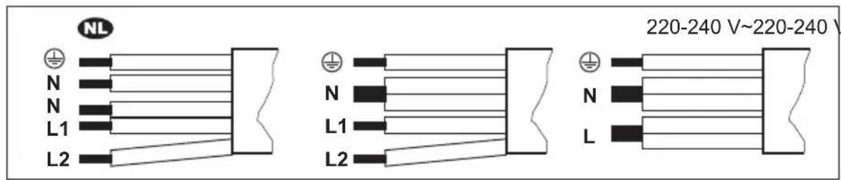
3.3 Connection cable
- The hob is supplied with a connection cable.
- To replace the damaged mains cable, use the cable type: H05V2V2-F which withstands a temperature of 90 °C or higher. A single wire must have a minimal cross section in accordance with the table below. Speak to your local Service Centre. The connection cable may only be replaced by a qualified electrician.

WARNING!
All electrical connections must be made by a qualified electrician.

CAUTION!
Connections via contact plugs are forbidden.

CAUTION!
Do not drill or solder the wire ends. It is forbidden.

CAUTION!
Do not connect the cable without cable end sleeve.
One-phase connection
- Remove the cable end sleeve from black, brown and blue wires.
- Remove a part of the insulation of the brown, black and blue cable ends.
- Connect the ends of black and brown cables.
- Apply a new wire end sleeve on the shared wire's end (special tool required).
- Connect the ends of two blue cables.
- Apply a new wire end sleeve on the shared wire's end (special tool required).
Two-phase connection
-
Remove the cable end sleeve from blue wires.
-
Remove a part of the insulation of the blue cable ends.
-
Connect the ends of two blue cables.
-
Apply a new end wire sleeve on the shared wire's end (special tool required).
text_image
NL 220-240 V~220-240 V N N L1 L2 N L1 L2 N L
220 - 240 V\~
Two-phase connection: 400 V2N\~ One-phase connection: 220 - 240 V\~
5x1,5 mm ^2 5x1,5 mm ^2 or 4x2,5 mm ^2 5x1,5 mm ^2 or 3x4 mm ^2

Green - yellow Green + yellow Green - yellow

N Blue and blue N Blue and blue N Blue and blue
L1 Black L1 Black L Black and brown
L2 Brown L2 Brown
3.4 Assembly
If you install the hob under a hood, please see the installation instructions of the hood for the minimum distance between the appliances.
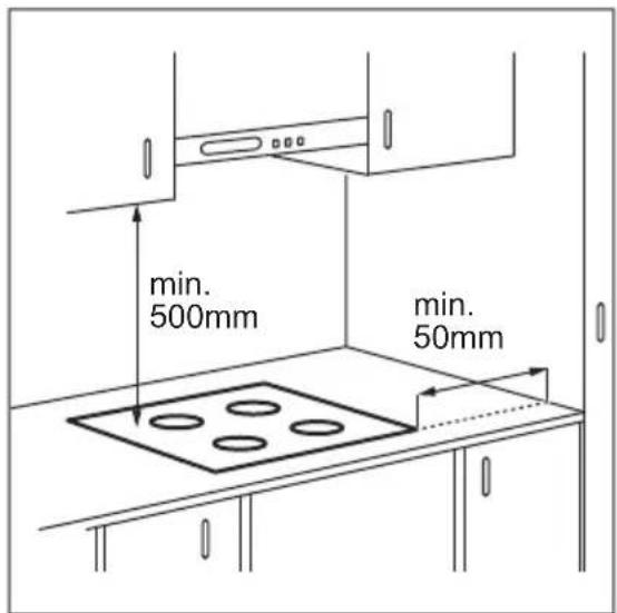
If the appliance is installed above a drawer, the hob ventilation can warm up the items stored in the drawer during the cooking process.
text_image
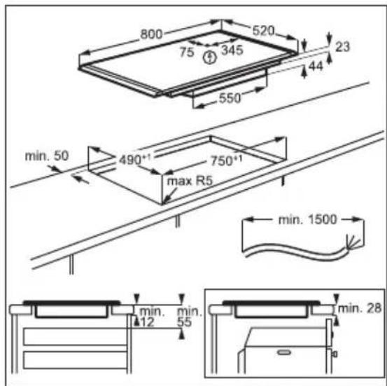
800 520 75 345 44 23 550 min. 50 490°1 max R5 750°1 min. 1500 min. 12 min. 55 min. 28Find the video tutorial "How to install your AEG Induction Hob - Worktop installation" by typing out the full name indicated in the graphic below.

YouTube
www.youtube.com/electrolux
www.youtube.com/aeg
How to install your AEG Induction Hob - Worktop installation
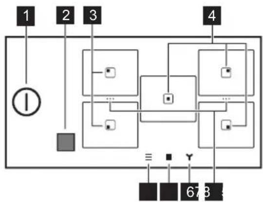
4. PRODUCT DESCRIPTION
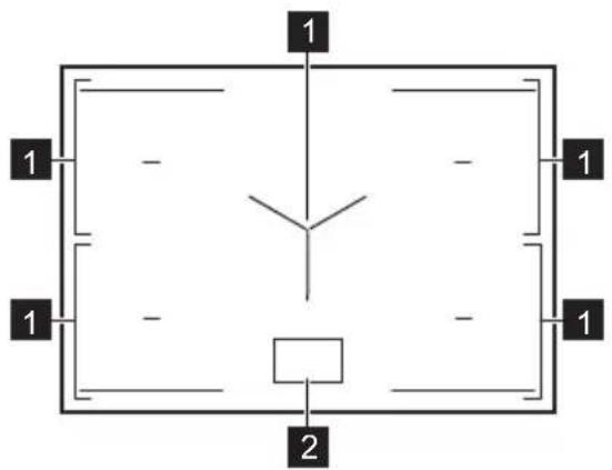
4.1 Cooking surface layout

text_image
1 1 - - 1 1 - - 1 21 Induction cooking zone
2 Control panel
i
For detailed information on the sizes of the cooking zones refer to "Technical data".
4.2 Control panel layout
Main view
flowchart
graph TD
    A["①"] --> B["Square"]
    C["1"] --> D["Square"]
    E["2"] --> F["Square"]
    G["3"] --> H["Square"]
    I["4"] --> J["Square"]
    K["678"] --> L["Square"]
    M["≡"] --> N["Square"]
    O["Y"] --> P["Square"]
    Q["●"] --> R["Square"]
    S["●"] --> T["Square"]
| Symbol Description | ||
| 1 | 1 | To activate and deactivate the hob. |
| 2 | Window of the Hob^2Hood infrared signal communicator. Do not cover it. | |
| 3 | Zone with Pan-frying and Boiling functions. | |
| 4 | Zone with Boiling function. | |
| 5 | ... | A shortcut for Bridge. To merge two side cooking zones to create one cooking area or to split the merged zones. |
| 6 | To set the hood functions. | |
| 7 | To open the zone overview. | |
Symbol Description
8

To open the Menu.
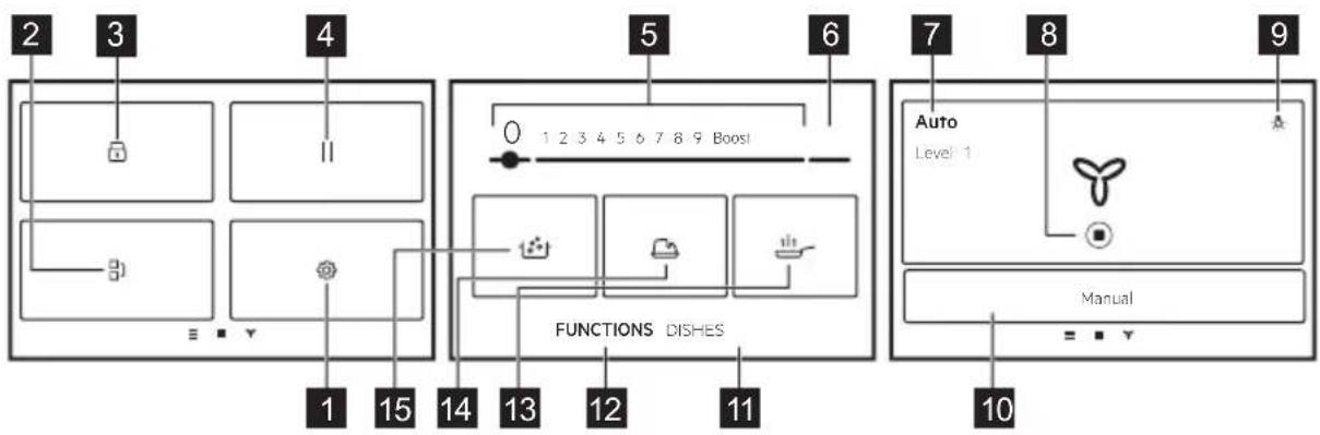
Expanded view
flowchart
graph TD
    subgraph Panel_1
        A["Component 2"] --> B["Component 3"]
        C["Component 4"] --> D["Component 5"]
        E["Component 6"] --> F["Functional Dishes"]
    end
    subgraph Panel_2
        G["Component 1"] --> H["Component 15"]
        I["Component 14"] --> J["Component 13"]
        K["Component 12"] --> L["Component 11"]
    end
    subgraph Panel_3
        M["Component 0"] --> N["Functional Dishes"]
        O["Component 1"] --> P["Functional Dishes"]
        Q["Component 2"] --> R["Functional Dishes"]
        S["Component 3"] --> T["Functional Dishes"]
    end
    subgraph Panel_4
        U["Component 1"] --> V["Functional Dishes"]
        W["Component 2"] --> X["Functional Dishes"]
        Y["Component 3"] --> Z["Functional Dishes"]
        AA["Component 4"] --> AB["Functional Dishes"]
    end
    subgraph Panel_5
        AC["Functional Dishes"] --> AD["Functional Dishes"]
        AE["Functional Dishes"] --> AF["Functional Dishes"]
        AG["Functional Dishes"] --> AH["Functional Dishes"]
    end
    subgraph Panel_6
        AI["Functional Dishes"] --> AJ["Functional Dishes"]
        AK["Functional Dishes"] --> AL["Functional Dishes"]
        AM["Functional Dishes"] --> AN["Functional Dishes"]
    end
    subgraph Panel_7
        AO["Functional Dishes"] --> AP["Functional Dishes"]
        AQ["Functional Dishes"] --> AR["Functional Dishes"]
        AS["Functional Dishes"] --> AT["Functional Dishes"]
    end
    subgraph Panel_8
        AU["Functional Dishes"] --> AV["Functional Dishes"]
        AW["Functional Dishes"] --> AX["Functional Dishes"]
        AY["Functional Dishes"] --> AZ["Functional Dishes"]
    end
    subgraph Panel_9
        BA["Functional Dishes"] --> BB["Functional Dishes"]
        BC["Functional Dishes"] --> BD["Functional Dishes"]
        BE["Functional Dishes"] --> BF["Functional Dishes"]
    end
Symbol Description
1

Settings. To open the settings of the hob.
2

Bridge. To connect two side cooking zones so that they operate as one.
3

Lock. To lock / unlock the control panel.
4

Pause. To set all cooking zones that operate to the lowest heat setting.
5
1 - 9 To set a heat setting.
6
Boost To activate the maximum heat setting.
7
Manual / Auto To show the current setting of the hood fan.
8

To stop / restart the hood.
9

To turn the hood light on or off.
10
Manual / Auto To switch to the manual or auto mode of the hood.
11
Dishes To select preset automatic programs for different types of food.
12
FUNCTIONS To select automatic programs for different methods of cooking.
13

Pan-frying. To fry with automatically controlled heat levels, dedicated to various types of food.
14

Melting. To melt different products, e.g. chocolate or butter.
15

Boiling. To automatically adjust the temperature of water so that it does not boil over once it reaches the boiling point.
Display navigation
| Symbol Description | |
| OK | To confirm the selection or setting. |
| X | To close the pop-up window. |
| To collapse / expand the instructions on the display. | |
| To activate / deactivate the option. | |
| <> | To go back / forward one level in the Menu. |
5. BEFORE FIRST USE

WARNING!
Refer to Safety chapters.
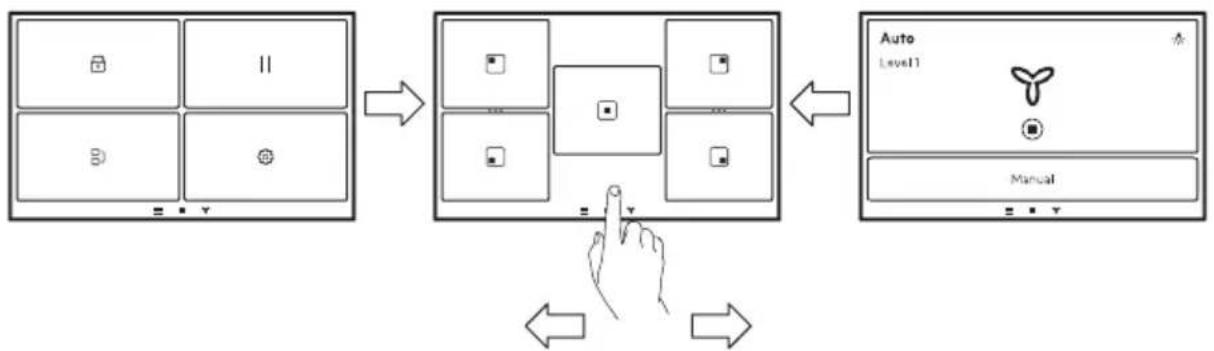
5.1 Navigating the display
flowchart
graph TD
    A["Screen Screen"] --> B["Keyboard"]
    B --> C["Keyboard"]
    C --> D["Keyboard"]
    D --> E["Keyboard"]
    E --> F["Auto Level1"]
    F --> G["Manual"]
    G --> H["Hand Icon"]
    H --> I["Arrow to Button"]
    I --> J["Arrow to Left"]
    J --> K["Arrow to Right"]
To navigate between the screens, tap on the symbols on the bottom of the display. You can also swipe to the left to manage the settings for Hob ^2 Hood or to the right to reach the Menu.
5.2 First connection to the mains
When you connect the hob to the mains you have to set Language, Brightness and Volume.
You can change the setting in Menu > Settings > Setup. Refer to "Daily use".
5.3 Using the display
- Only the backlit symbols can be used.
• To activate a given option, touch the relevant symbol on the display. - The selected function is activated when you remove the finger from the display.
• To scroll the available options, use a quick gesture or drag your finger across the
display. The speed of the gesture determines how fast the screen moves.
- The scrolling can stop by itself or you can stop it immediately if you touch the display.
- You can change most of the parameters shown on the display when you touch the relevant symbols.
• To select the required function or time you can scroll through the list and / or touch the option you want to choose. - When the hob is activated and some of the symbols disappear from the display, touch it again. All the symbols come back on.
- For certain functions, when you start them, a pop-up window with additional information appears.
5.4 FlexPower
FlexPower defines how much power is used by the hob in total, within the limits of the house installation fuses.
Originally the appliance works at the highest possible power level. You can change the maximum power if the installation does not support the full power.

CAUTION!
Make sure that the selected power fits the house installation fuses.

If the power level is lower than 3500 W, you cannot activate any automatic programs (Dishes or FUNCTIONS).
- Make sure that all cooking zones are deactivated.
- Touch on the display to open the Menu.
- Select Settings > Setup > FlexPower and choose the appropriate power level.
- Touch or . Follow the instructions on the display to confirm your selection.
6. DAILY USE

WARNING!
Refer to Safety chapters.
6.1 Activating and deactivating
Touch ① for 1 second to activate or deactivate the hob.
6.2 Automatic Switch Off
The function deactivates the hob automatically if:
- all cooking zones are deactivated,
- you do not set the heat setting after you activate the hob,
- you spill or put something on the control panel for more than 10 seconds (a pan, a cloth, etc.). An acoustic signal sounds and the hob deactivates. Remove the object or clean the control panel.
- the hob gets too hot (e.g. when a saucepan boils dry). Let the cooking zone cool down before you use the hob again.
- you use incorrect cookware or there is no cookware on a given zone. The induction cooking zone deactivates automatically after 50 seconds.
- you do not deactivate a cooking zone or change the heat setting. After some time a message comes on and the hob deactivates.
The relation between the heat setting and the time after which the hob deactivates:
Heat setting The hob deactivates after
| 1 - 2 6 hours |
| 3 - 5 5 hours |
| 6 4 hours |
| 7 - 9 1.5 hour |

When you use Pan-frying the hob deactivates after 1.5 hours. For Melting the hob deactivates after 6 hours.
6.3 Pot detection
This feature detects if pots were placed on the cooking zones and deactivates the cooking zones if the cookware is no longer detectable.
- If you put cookware on a cooking zone first and then activate the hob, a grey bar appears on the overview of the corresponding cooking zone.
- The bar will not appear if there is no cookware on the cooking zone or the cookware cannot be detected due to its incorrect placement or unsuitable material.
- If you remove the cookware from an activated cooking zone and set it aside temporarily, the corresponding cooking zone overview will start blinking. If you do not place the cookware back on the activated cooking zone within 120 seconds, the cooking zone will automatically deactivate. To resume cooking, make sure to put the cookware back on the cooking zones before the indicated timeout.
6.4 Using the cooking zones
Induction cooking zones adapt to the dimensions of the bottom of the cookware automatically.

Make sure that the cookware is suitable for induction hobs. For more information on cookware types refer to "Hints and tips". Check the size of the cookware in "Technical data".
To activate the cooking zone place the cookware in the centre of the cooking zone and touch the relevant zone symbol. The available programs appear on the display. Set the heat level or select one of the automatic functions. To get back to the main view touch ✗ in the top right corner.
You can cook with large cookware placed on two cooking zones at the same time using Bridge.
natural_image
Two technical diagrams showing circular components inside rectangular chambers, one with a checkmark and the other with an arrow (no text or symbols)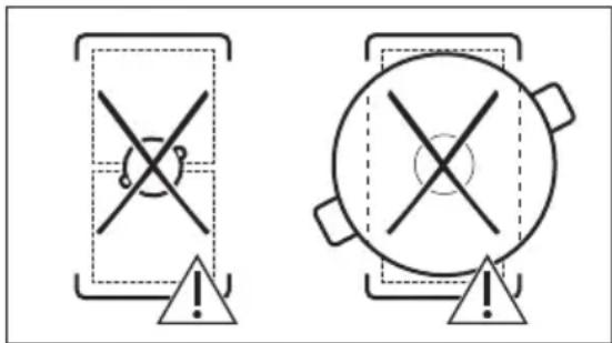
text_image
Two warning symbols: a cross symbol inside a shield and a circle with cross inside a pot, both marked with an exclamation mark.When other cooking zones are active the heat setting for the zone you want to use may be limited. Refer to "Power Management".
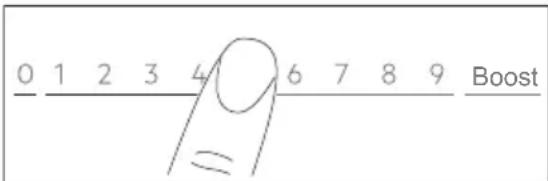
6.5 Heat setting
- Activate the hob.
-
Place the pot on the selected cooking zone and touch the relevant zone symbol.
-
Touch or slide your finger to set the heat setting.
The power level icons 1-9 become bigger and the bar below turns red to indicate the current power setting. When the power level is selected the screen changes to the expanded screen view.
text_image
0 1 2 3 4 6 7 8 9 BoostYou can also change the heat setting on the zone overview screen. To go to the zone overview screen, touch the centre of the expanded screen view. To change the heat level touch — or +To open the expanded screen view, touch the power level.
6.6 Boost
This function makes more power available to the induction cooking zones. The function can be activated for the induction cooking zone only for a limited time. After this time the induction cooking zone automatically sets back to the highest heat setting.
- Select the cooking zone.
- Touch Boost to activate the function.
The function deactivates automatically. To deactivate the function manually select the zone and change its heat setting to 0.

Boost does not work when Bridge function is active or when the power within one phase is insufficient (refer to "Power Management").

For maximum duration values, refer to "Technical data".
6.7 OptiHeat Control (3 step Residual heat indicator)

WARNING!
As long as the indicator III /III is on, there is a risk of burns from residual heat.
The induction cooking zones produce the heat necessary for the cooking process directly in the bottom of the cookware. The glass ceramic is heated by the heat of the cookware.
The indicators appear when a cooking zone is hot. They show the level of the residual heat for the cooking zones you are currently using:
III - continue cooking,
II - keep warm,
I - residual heat.
The indicator may also appear:
- for the neighbouring cooking zones even if you are not using them,
- when hot cookware is placed on a cold cooking zone,
- when the hob is deactivated but the cooking zone is still hot.
The indicator disappears when the cooking zone has cooled down.
6.8 Keep Warm mode
This function keeps food warm with the low temperature setting.
Keep Warm mode is available only when the cooking zone is still warm after the finished cooking process (with a visible residual heat
icon) and the cookware remains on the zone. The function does not work with a cold cooking zone.
- Touch to activate the Keep Warm mode.
The Keep Warm mode operates until turned off. - To stop the function touch in the upper left corner of the display.
You can set a timer, if needed. Refer to "Timer options".
6.9 Timer options

ECO Timer
Use this function to specify how long a cooking zone should operate during a single cooking session.
To save energy, the heater of the cooking zone deactivates before the ECO Timer sounds. The difference in the operation time depends on the heat setting level and the length of the cooking operation.
You can use this function when the cooking zone is activated. You can set the function for each cooking zone separately.
- Set the heat setting for the appropriate cooking zone first and then set the function.
-
Touch the zone symbol.
-
Touch ⏻.
The timer menu window appears on the display.
-
Tick the Stop zone box to activate the function.
-
Set the time.
-
Touch OK to confirm.
You can also choose X to cancel your selection.
You can change the ECO Timer settings
during cooking: touch +s with the timer value, then touch EDIT.
When the timer runs out, a signal sounds and a pop-up window appears. Touch OK to stop the signal.
To deactivate the function, set the heat setting to 0. Alternatively, touch +with the timer value, touch × and confirm your choice when a pop-up window appears.
Timer
You can use this function when the cooking zone is activated.
The function has no effect on any other function operating concurrently.
-
Select any cooking zone. The relevant slider appears on the display.
-
Touch ⏻. The timer menu window appears on the display.
-
Untick the Stop zone box to activate the function.
-
Set the time.
-
Touch OK to confirm. You can also choose ✗ to cancel your selection.
You can change the Timer settings during cooking: touch 🔒 with the timer value, then touch EDIT.
When the timer runs out, a signal sounds and a pop-up window appears. Touch OK to stop the signal.
To deactivate the function touch with the timer value, touch X and confirm your choice when a pop-up window appears.
6.10 [7] Bridge
This function connects two cooking zones and they operate as one with the same heat setting. You can use it to cook with large cookware.
Cookware must cover the centres of both zones. If the cookware is located between the two centres, the function will not be activated.
- Place the cookware on the cooking zones.
-
Touch on the display to open the Menu and select Bridge. You can also touch the shortcut in the zone overview.
-
Set the heat setting. To deactivate the function, touch the shortcut …. The cooking zones resume operating independently.
6.11 Pause
This function sets all cooking zones that operate to the lowest heat setting.
When the function operates only ① and RESUME buttons can be used. All other symbols on the control panel are locked.
The function does not stop the timer functions. When the timer function ends, tap anywhere on the screen to stop the acoustic signal.
- Touch to open the Menu.
- Touch || to activate the function.
The heat setting is lowered to 1.
To deactivate the function touch RESUME.
The previous heat settings will be restored.
6.12 Lock
You can lock the control panel while the hob operates. It prevents an accidental change of the heat setting.
- Set the heat setting.
- Touch to open the Menu.
- Touch to activate the function.
To deactivate the function, press and hold UNLOCK for 4 seconds.
i
When you deactivate the hob, you also deactivate this function.
6.13 Child Lock
This function prevents an accidental operation of the hob.
- Touch to open the Menu.
- Select Settings > Setup > Child Lock.
- Turn the switch on and touch the letters E-U-O in the alphabetical order to activate the function.
To deactivate the function turn the switch off.
It may take some time for the function to work after activation.
6.14 FUNCTIONS: Pan-frying
This function lets you set an appropriate heat setting level to fry your food. The hob adjusts the temperature to different types of food and maintains it throughout cooking. Once the heat setting level is set, no manual temperature adjustment is necessary.

CAUTION!
Use only cold cookware. Do not leave the hob unattended while the function is operating.
- Place a pan without oil / fat on one of the cooking zones on the left side. You can use a single cooking zone or connect both zones using Bridge.
- Select FUNCTIONS > Pan-frying.
- Choose a frying level.
Preheating starts. - Set a timer function, if needed. The timer starts immediately.
Once the pan reaches the intended temperature an acoustic signal sounds and a pop-up window appears. You can put oil and food inside the pan now. To close the window and start frying touch OK. To stop the function manually touch 0 on the control bar.
Hints and tips:
- Follow the instructions on the display for when to flip the food over or to adjust the heat level.
- You can change the default heat level, if needed.
- For thick pieces of food or raw potatoes use a lid during the first 10 min of frying.
- Heavy pans may take longer to heat-up.
- Use laminated pans with low heat level to prevent overheating and damage of the cookware.
- Do not use thin enamelled cookware. It can be overheated and damaged.
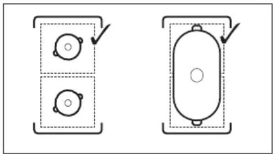
Correct pans for Pan-frying function
Use only pans with flat bottoms. To check if the pan is correct:
-
Put your pan upside down.
-
Put a ruler on the bottom of the pan.
- Try to put a coin of 1, 2, or 5 Euro Cent (or any coin with similar thickness, approx. 1.7 mm) between the ruler and the bottom of the pan.
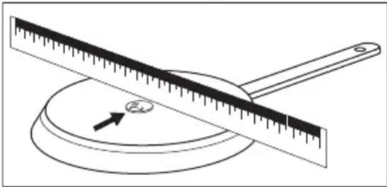
natural_image
Simple line drawing of a balance scale with an arrow indicating the pointer (no text or symbols)a. The pan is incorrect if you can put the coin between the ruler and the pan.

text_image
Diagram showing a ruler with an 'X' mark above it and a blank rectangular object below, likely indicating measurement or calibration.b. The pan is correct if you cannot put the coin between the ruler and the pan.
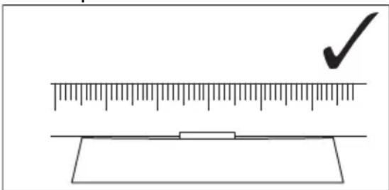
text_image
Diagram showing a ruler measuring a rectangular object with a checkmark indicating the measurement.6.15 FUNCTIONS: Boiling
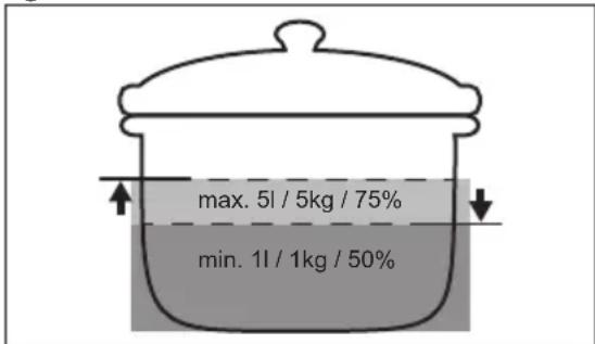
This function adjusts the heat setting level automatically so that water does not boil over once it reaches the boiling point.

The function is available on all cooking zones. If there is any residual heat (I / II/ III) on the cooking zone you want to use, an acoustic signal sounds and the function does not start.
The function does not work with non-stick cookware.

CAUTION!
Do not use the function with empty cookware. Do not leave the hob unattended while the function is operating.
- Place a pot filled with at least 1 l of water on the cooking zone.
- Select FUNCTIONS > Boiling.
-
Set a timer function, if needed.
The timer starts immediately. -
To stop the function manually touch the upper left corner of the display.

Once the boiling point has been reached, the hob automatically reduces the heat setting level. At this point you can also adjust it manually as needed.
Hints and tips:
- The function is best suited for boiling water and cooking potatoes.
- The function may not work properly for kettles and stovetop espresso pots.
- Fill between half to three quarters of the pot with cold tap water leaving 4 cm from the rim of the pot empty. Do not use less than 1 or more than 5 litres of water. Make sure the total weight of the water (or the water and potatoes) ranges between 1-5 kg.
text_image
max. 5l / 5kg / 75% min. 1l / 1kg / 50%• To achieve the best results cook only whole, unpeeled, medium-sized potatoes. Make sure you do not pack potatoes too tightly.
- Avoid producing external vibrations (e.g. from using a blender or placing a mobile phone next to the hob) when the function is running.
- Depending on the type of food and cookware you can adjust the heat setting after the boiling point has been reached.
- Add salt once the boiling point has been reached.
- Use a lid to save energy.
6.16 FUNCTIONS: Melting
You can use this function to melt products, e.g. chocolate or butter. You can use the function only for one cooking zone at a time.

CAUTION!
Do not leave the hob unattended while the function is operating.
- Place cookware on the cooking zone.
- Select FUNCTIONS > Melting.
- Set a timer function, if needed.
- Touch OK.
To stop the function manually touch ☑ in the upper left corner of the display.
6.17 Dishes
This function helps you prepare different foods using preset programs dedicated to specific food categories. The availability of programs depends on the cooking zone.

CAUTION!
Do not leave the hob unattended while the function is operating.
- Place cookware on the cooking zone. You can use a single cooking zone or connect two side zones using Bridge.
- Select Dishes.
- Select the food type.
- Set a timer function, if needed.
- Follow the instructions on the display. Depending on the food type and the selected program you can set and modify details, e.g. level of doneness, level of heat for frying, etc.
Hints and tips:
- The most often cooked dishes are automatically added to the list of Most Cooked.
- Some dishes have long names which cannot be fully displayed on the list. To view the full name of a dish, touch "...".
- You can manually add programs to the list of Favourites ♥
- You can hide certain programs by touching ⏻To restore the programs, go to Settings > Setup > Dishes.
6.18 Hob²Hood
It is an automatic function which connects the hob to a suitable hood. Both the hob and the hood have an infrared signal communicator. The speed of the fan is defined and adjusted automatically based on the mode setting and the temperature of the hottest cookware on the hob. You can also operate the fan manually from the hob or the hood itself.
i
If you change the fan speed on the hood, the default connection with the hob will be deactivated. To reactivate the function, turn both appliances off and on again.
i
In some hoods the function might be disabled by default. In such cases, activate the function first on the hood, then on the hob. For more information refer to the hood user manual.
Setting the automatic fan mode
To set the hood to an automatic mode, choose between the following set fan speeds: Mode 2 - Mode 6. The hood reacts whenever you operate the hob. You can set the hob to activate only the light by selecting Mode 1.
-
Touch 三.
-
Select Settings > Hob ^2 Hood.
-
Turn a switch on to activate the hood.
All automatic modes appear as a list.
-
Choose the mode.
-
Touch on to save the selection and leave.
To check the current fan speed level, touch
. The fan speed level is visible in the top left corner of the display. To turn off the fan, touch ☐. To turn on the fan, touch ▶
| Automatic modes | Auto-matic light | Boiling1) | Frying2) |
| Fan speed | |||
| Off -- | |||
| Mode 1 On -- | |||
| Automatic modes | Auto-matic light | Boiling1) | Frying2) |
| Fan speed | |||
| Mode 2 3) | On 1 1 | ||
| Mode 3 On - 1 | |||
| Mode 4 On 1 1 | |||
| Mode 5 On 1 2 | |||
| Mode 6 On 2 3 | |||
1) The hob detects the boiling process and sets fan speed in accordance with the automatic mode.
2) The hob detects the frying process and sets fan speed in accordance with the automatic mode.
3) This mode activates the fan and the light and does not rely on the temperature.
Setting the manual fan mode
You can adjust the fan speed level manually.
- Touch
- Touch Manual.
A control bar appears with the current fan speed.
- Touch or slide your finger to set the fan speed level.
To activate the maximum fan speed level touch Boost. The fan runs in Boost mode for a certain time. After that time the fan speed level automatically changes to 3. To deactivate Boost manually, press 0.
Hood light
You can set the hob to activate the light automatically whenever you activate the hob. To do so, set the automatic mode to Mode 1 - Mode 6. You can also manually activate or deactivate the light on the hood.
Activating the light manually
- Touch
- Touch to turn on the light.
To turn off the light touch again.

6.19 Language
- Touch to open the Menu.
-
Select Settings > Setup > Language.
-
Choose the language from the list.
To save the selection touch X or . Then choose YES in the pop-up window.
If you chose the wrong language, touch
A list appears. Select the first option from the top on the left, then the second option from the top on the right. Scroll down to choose the correct language from the list. When the pop-up window appears, choose the option on the right.
6.20 Key Tones / Volume
You can choose the type of sound your hob emits or turn the sounds off entirely. You can choose between the click (default) or beep.
You can also choose the volume level.
- Touch on the display to open the Menu.
- Select Settings > Setup > Key Tones / Volume.
- Choose the appropriate option. The setting is saved automatically.
6.21 Brightness
You can change the brightness of the display. There are 5 brightness levels, 1 is the lowest and 5 is the highest.
- Touch to open the Menu.
- Select Settings > Setup > Brightness.
- Choose the appropriate level. The setting is saved automatically.
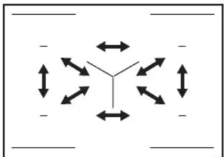
6.22 Power Management
If multiple zones are active and the consumed power exceeds the limitation of the power supply, this function divides the available power between all cooking zones (connected to the same phase). The hob controls heat settings to protect the fuses of the house installation.
- Cooking zones are grouped according to the location and number of the phases in the hob. Each phase has a maximum electricity loading of 3680 W. If the hob reaches the limit of maximum available power within one phase, the power of the
cooking zones will be automatically reduced.
- The heat setting of the cooking zone selected first (or a cooking zone using FUNCTIONS or Dishes) is always prioritised. The remaining power will be divided between the other cooking zones according to the order of selection.
-
The colour of the control bar shows the available heat setting options:
-
red - the current heat setting,
- white - the maximum available heat setting,
– light grey - the unavailable heat setting (Power Management operates).
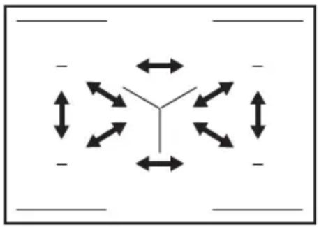
- If a higher heat setting is not available reduce it for the other cooking zones first. Refer to the illustration for possible combinations in which power can be distributed among the cooking zones.
natural_image
Pure diagram of directional arrows and symbols without any text or labelsIf total power of the hob is limited (1500 W - 6000 W) the function distributes the available power between all cooking zones. Refer to chapter "FlexPower".
flowchart
graph TD
    A["Start"] --> B{Y}
    B --> C["Right"]
    B --> D["Left"]
    B --> E["Down"]
    B --> F["Up"]
    C --> G["Right"]
    D --> H["Left"]
    E --> I["Down"]
    F --> J["Up"]
    G --> K["Right"]
    H --> L["Left"]
    I --> M["Down"]
7. HINTS AND TIPS

WARNING!
Refer to Safety chapters.
7.1 Cookware

For induction cooking zones a strong electro-magnetic field creates the heat in the cookware very quickly.
Use the induction cooking zones with suitable cookware.
- To prevent overheating and improve the performance of the zones, the cookware must be as thick and flat as possible.
- For Pan-frying function only use pans with flat bottom.
- Ensure cookware bases are clean and dry before placing on the hob surface.
• Always be careful no to slide or rub the cookware on the edges and corners of the glass or the side trim as it may chip or damage the glass surface.
Cookware material
- correct: cast iron, steel, enamelled steel, stainless steel, multi-layer bottom (with a correct marking from a manufacturer).
- not correct: aluminium, copper, brass, glass, ceramic, porcelain.
Cookware is suitable for an induction hob if:
• water boils very quickly on a zone set to the highest heat setting.
- a magnet pulls on to the bottom of the cookware.
Cookware dimensions
- Induction cooking zones adapt to the dimension of the bottom of the cookware automatically.
- The cooking zone efficiency is related to the diameter of the cookware. The cookware with a diameter smaller than the minimum receives only a part of the power generated by the cooking zone.
- For both safety reasons and optimal cooking results, do not use cookware larger than indicated in "Cooking zones
specification". Avoid keeping cookware close to the control panel during the cooking session. This might impact the functioning of the control panel or accidentally activate hob functions.

Refer to "Technical data".
7.2 Noises during operation
If you can hear:
- crack noise: cookware is made of different materials (a sandwich construction).
- whistle sound: you use a cooking zone with a high power level and the cookware is made of different materials (a sandwich construction).
- humming: you use a high power level.
- clicking: electric switching occurs, cookware is detected after you place it on the hob.
- hissing, buzzing: the fan operates.
The noises are normal and do not indicate any malfunction.
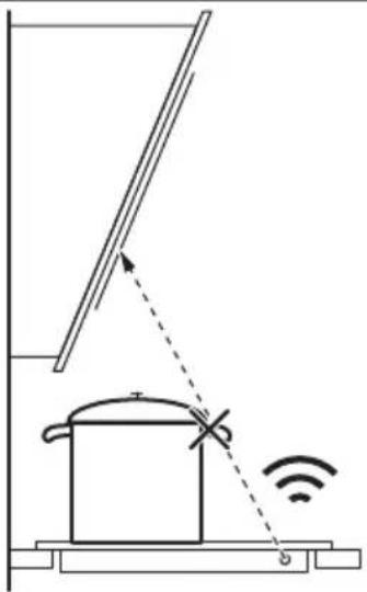
7.3 Hints and tips for Hob ^2 Hood
When you operate the hob with the function:
- Protect the hood panel from direct sunlight.
- Do not spot halogen light on the hood panel.
- Do not cover the hob control panel.
- Do not interrupt the signal between the hob and the hood (e.g. with the hand, a cookware handle or a tall pot). See the picture.
The hood pictured below is for illustration purpose only.
natural_image
Diagram of a simple electrical circuit with a pot, wires, and an antenna (no text or symbols)i
Keep the window of the Hob ^2 Hood infrared signal communicator clean.
i
Other remotely controlled appliances may block the signal. Do not use any such appliances near to the hob while Hob ^2 Hood is on.
Cooker hoods with the Hob²Hood function
To find the full range of cooker hoods which work with this function refer to our consumer website. The AEG cooker hoods that work with this function must have the symbol 📞
8. CARE AND CLEANING

WARNING!
Refer to Safety chapters.
8.1 General information
- Clean the hob after each use.
• Always use cookware with a clean base.
• Scratches or dark stains on the surface have no effect on how the hob operates. - Use a special cleaning agent suitable for the surface of the hob.
• Always use a scraper recommended for hobs with a glass surface. Use the scraper only as an additional tool for cleaning the glass after the standard cleaning procedure.

WARNING!
Do not use knives or any other sharp, metal tools to clean the glass surface.
- For the metal side trim, use only a dishwashing detergent with warm water. Use a cloth to clean and wipe the trim.

WARNING!
Do not use the mildly abrasive cleaning milk, any polishing detergents, scrapers, or the hard layer of a sponge to clean the side trim.
- The gap between the glass surface and the side trim may gather dirt and small particles of food. Use a wooden toothpick to clean the gap between the glass surface and the side trim.

WARNING!
Do not use any sharp metal tools to clean the gap as they may widen the gap and damage the side trim or the glass surface.
8.2 Cleaning the hob
- Remove immediately: melted plastic, plastic foil, salt, sugar and food with sugar, otherwise, the dirt can cause damage to the hob. Take care to avoid burns. Use a special hob scraper on the glass surface at an acute angle and move the blade on the surface.
- Remove when the hob is sufficiently cool: limescale rings, water rings, fat
stains, shiny metallic discoloration. Clean the hob with a moist cloth and a non-abrasive detergent. After cleaning, wipe the hob dry with a soft cloth.
- Remove shiny metallic discoloration: use a solution of water with vinegar and clean the glass surface with a cloth.
9. TROUBLESHOOTING

WARNING!
Refer to Safety chapters.
9.1 What to do if...
| Problem Possible cause Remedy | ||
| You cannot activate or operate the hob. | The hob is not connected to an electrical supply or it is connected incorrectly. | Check if the hob is correctly connected to the electrical supply. Refer to the connection diagram. |
| The fuse is blown. Make sure that the fuse is the cause | of the malfunction. If the fuse is blown again and again, contact a qualified electrician. | |
| You did not set the heat setting for 60 seconds. | Activate the hob again and set the heat setting in less than 60 seconds. | |
| You touched 2 or more sensor fields at the same time. | Touch only one sensor field. | |
| Pause operates. Refer to "Daily use". | ||
| The display does not react to the touch. | Part of the display is covered or the pots are placed too near to the display.There is some liquid or an object on the display. | Remove the objects. Move the pots away from the display.Clean the display, wait until the appliance is cold. Disconnect the hob from the electrical supply. After 1 min, connect the hob again. |
| An acoustic signal sounds and the hob deactivates.An acoustic signal sounds when the hob is deactivated. | You put something on one or more sensor fields. | Remove the object from the sensor fields. |
| The hob deactivates. You put something on the sensor field | field | Remove the object from the sensor field. |
| Residual heat indicator does not come on. | The zone is not hot because it operated only for a short time or the sensor under the hob surface is damaged. | If the zone operated sufficiently long to be hot, speak to an Authorised Service Centre. |
| You cannot activate the highest heat setting. | Another zone is already set to the highest heat setting. | First reduce the power of the other zone. |
| The FlexPower level is too low. Change the maximum power in the | Menu. Refer to "Before first use". | |
| The sensor fields become hot. The cookware is too large or you put it too near to the controls. | Put large cookware on the rear zones, if possible. | |
| Hob ^2 Hood does not work. You covered the control panel. Remove the object from the control panel. | ||
| Hob ^2 Hood screen is not visible. Hob ^2 Hood is turned off in the settings. | Go to settings/Hob ^2 Hood and activate the function. | |
| Hob ^2 Hood operates, but only the light is on. | You activated Mode 1. Change the mode to Mode 1 - Mode 6or wait until the automatic mode starts. | |
| Hob ^2 Hood Modes 1 - 6 operate, but the light is off. | There might be a problem with the light bulb. | Contact an Authorised Service Centre. |
| There is no sound when you touch the panel sensor fields. | The sounds are deactivated. Activate the sounds. Refer to "Daily use". | |
| Wrong language was set. You changed the language by mistake. | Follow the instruction in "Daily use", "Language" to change the wrong language. | |
| A cooking zone deactivates. Automatic Switch Off deactivates the cooking zone. | Deactivate the hob and activate it again.Refer to "Daily use". | |
| and a message come on. | Lock operates. Refer to "Daily use". | |
| E - U - O appears. Child Lock operates. Refer to "Daily use". | ||
| The power level bar blinks. There is no cookware on the zone. Put cookware on the zone. | ||
| The cookware is unsuitable. | Use suitable cookware. Refer to "Hints and tips". | |
| The diameter of the bottom of the cookware is too small for the zone. | Use cookware with correct dimensions. Refer to "Technical data". | |
| E3 comes on. | The electrical connection is faulty. | Disconnect the hob from the mains and check the connection. Refer to "Installation". |
| E4 comes on. | The zone temperature sensor detects a too high or too low temperature. | Let the cooking zone cool down or raise the ambient temperature above 15°C.If the problem persists, contact the Authorised Service Centre. |
| E7 comes on. | The cooling fan is blocked. | Make sure that nothing is blocking the fan. If the fan is not blocked by anything and the problem persists, contact the Authorised Service Centre. |
| You can hear a constant beep noise. | The electrical connection is incorrect. | Disconnect the hob from the electrical supply. Ask a qualified electrician to check the installation. |
| Cookware heats up longer than 5 min. | The bottom of the cookware is not induction compatible. | Use cookware with a suitable bot-tom (flat, magnetic). Refer to "Hints and tips". |
| The FlexPower reduces the maxi-mum power. | Refer to "Daily use", Power Man-agement. | |
| Boiling function does not start. Residual heat is still active on this zone. | Wait until the zone cools off or use another, cold zone. | |
| Boiling function does not stop. There might not be enough water in the pot (vibrations cannot be detec-ted) or the water is already too warm. | Use a minimum of 1 l of cold water per pot. | |
| Boiling function stops suddenly. The cookware is incompatible with the function. The function cannot detect vibrations made by the boil-ing water.The cookware might be too small for the cooking zone. | Do not use non-stick cookware with this function.Boil more water or switch to a cold zone. Do not add salt before water reaches the boiling point.Make sure the diameter of the cook-ware fits the size of the cooking zone. Place the cookware in the centre of the cooking zone. | |
| Heating up with Pan-frying function takes a long time. | Cookware is too small, too heavy or the bottom is uneven. | Refer to "Hints and tips". |
9.2 If you cannot find a solution...
If you cannot find a solution to the problem yourself, contact your dealer or an Authorised Service Centre. Give the data from the rating plate. Make sure, you operated the hob correctly. If not the servicing by a service
technician or dealer will not be free of charge, also during the warranty period. The information about guarantee period and Authorised Service Centres are in the guarantee booklet.
10. TECHNICAL DATA
10.1 Rating plate
Model NIG85M30AB PNC 949 598 058 00
Typ 62 D5A 01 AA 220 - 240 V / 400 V 2N, 50 Hz
Induction 7.35 kW Made in: Germany
Ser.Nr. 7.35 kW
AEG
10.2 Cooking zones specification
| Cooking zone Nominal power(maximum heat setting) [W] | Boost [W] Boost maxi-mum duration[min] | Cookware diameter [mm] |
| Left front 2300 3200 10 125 - 210 | ||
| Left rear 2300 3200 10 125 - 210 | ||
| Middle rear 2300 3200 10 125 - 210 | ||
| Right front 2300 3200 10 125 - 210 | ||
| Right rear 2300 3200 10 125 - 210 |
The power of the cooking zones can be different in some small range from the data in the table. It changes with the material and dimensions of the cookware.
For optimal cooking results use cookware no larger than the diameter in the table.
11. ENERGY EFFICIENCY
11.1 Product Information
| Model identification NIG85M30AB | ||
| Type of hob Built-In Hob | ||
| Number of cooking zones 5 | ||
| Heating technology Induction | ||
| Diameter of circular cooking zones (∅) Left front | 21.0 cm | |
| Left rear | 21.0 cm | |
| Middle rear | 21.0 cm | |
| Right front | 21.0 cm | |
| Right rear | 21.0 cm | |
| Energy consumption per cooking zone (EC electric cooking) | Left front | 180.8 Wh/kg |
| Left rear | 175.4 Wh/kg | |
| Middle rear | 184.4 Wh/kg | |
| Right front | 189.4 Wh/kg | |
| Right rear | 184.4 Wh/kg | |
| Energy consumption of the hob (EC electric hob) 182.9 Wh/kg | ||
IEC / EN 60350-2 - Household electric cooking appliances - Part 2: Hobs - Methods for measuring performance.
11.2 Energy saving
You can save energy during everyday cooking if you follow the hints below.
- When you heat up water, use only the amount you need.
- If it is possible, always put the lids on the cookware.
- Put the cookware directly in the centre of the cooking zone.
- Use the residual heat to keep the food warm or to melt it.
12. ENVIRONMENTAL CONCERNS
Recycle materials with the symbol Put the packaging in relevant containers to recycle it. Help protect the environment and human health by recycling waste of electrical and electronic appliances. Do not dispose of
appliances marked with the symbol 📀 with the household waste. Return the product to your local recycling facility or contact your municipal office.
PARIMATE TULEMUSTE SAAVUTAMISEKS
How to install your AEG Induction Hob - Worktop installation
4. TOOTE KIRJELDUS
4.1 Keeduala paigutus
text_image
1 1 - - 1 1 - - 1 2flowchart
graph TD
    A["①"] --> B["Square"]
    C["1"] --> D["Square"]
    E["2"] --> F["Square"]
    G["3"] --> H["Square"]
    I["4"] --> J["Square"]
    K["≡"] --> L["Square"]
    M["Y"] --> N["Square"]
    O["678"] --> P["Square"]
natural_image
Two technical diagrams showing circular components inside rectangular chambers, one with a checkmark and the other with a checkmark (no text or symbols)
text_image
Two warning symbols: a cross symbol inside a container and a circle with cross inside a pot, both marked with an exclamation mark.natural_image
Diagram of a balance scale with an arrow indicating the pointer (no text or symbols present)text_image
Diagram showing a ruler measuring a rectangular object with a cross mark symbol, likely illustrating a measurement or calibration concept.text_image
Diagram showing a ruler measuring a rectangular object with a checkmark indicating the measurement.6.15 FUNKTSIOONID: Keetmine
natural_image
Pure diagram of directional arrows and a Y-shaped symbol without any text or labelsnatural_image
Diagram of a smart air lift with a tank and signal detection, showing signal waves and an antenna (no text or symbols)8. PUHASTUS JA HOOLDUS

HOIATUS!
1. ⚠TURVALLISUUSTIEDOT
How to install your AEG Induction Hob - Worktop installation

4. TUOTEKUVAUS
flowchart
graph TD
    A["①"] --> B["Square"]
    C["1"] --> D["Square"]
    E["2"] --> F["Square"]
    G["3"] --> H["Square"]
    I["4"] --> J["Square"]
    K["≡"] --> L["Square"]
    M["Y"] --> N["Square"]
    O["67"] --> P["Square"]
    Q["8"] --> R["Square"]
natural_image
Two technical diagrams showing circular components inside rectangular chambers, one with a checkmark and the other with a checkmark (no text or symbols)
text_image
Two warning symbols: a cross symbol inside a shield and a circle with cross, both marked with an exclamation mark.natural_image
Diagram of a balance scale with an arrow indicating the pointer (no text or symbols present)text_image
Diagram showing a ruler measuring a rectangular object with a cross mark above it, likely illustrating a measurement or calibration concept.text_image
Diagram showing a ruler measuring a rectangular object with a checkmark indicating the measurement.6.16 TOIMINNOT: Sulatus
text_image
Diagram illustrating a smart air traffic detection system with a pot, signal waves, and antenna
How to install your AEG Induction Hob - Worktop installation
4. DESCRIPTION DE L'APPAREIL
flowchart
graph TD
    A["①"] --> B["Square"]
    C["1"] --> D["Square"]
    E["2"] --> F["Square"]
    G["3"] --> H["Square"]
    I["4"] --> J["Square"]
    K["678"] --> L["Square"]
    M["≡"] --> N["Square"]
    O["Y"] --> P["Square"]
    Q["●"] --> R["Square"]
    S["●"] --> T["Square"]
natural_image
Two technical diagrams showing circular components inside rectangular chambers, one with a checkmark and the other with an arrow (no text or symbols)
text_image
Two safety warning symbols: a shield with crosshair and warning triangle, and a circular device with crosshair and warning triangle.6.14 FONCTIONS: Poêlée
natural_image
Diagram of a balance scale with a ruler and pointer, no text or symbols presenttext_image
Diagram showing a ruler measuring a rectangular object with a cross mark symbol, likely illustrating a measurement or calibration concept.text_image
Diagram showing a ruler measuring a surface with a checkmark indicating the measurement point.6.15 ONCTIONS: Cuisson
natural_image
Pure diagram of Y-shaped structures with bidirectional arrows, no text or symbols presentnatural_image
Diagram of a simple electrical circuit with a pot, wires, and an antenna (no text or symbols)
text_image
NL N N L1 L2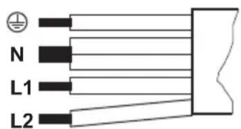
text_image
N L1 L2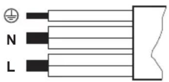
text_image
N L
220 - 240 V\~
How to install your AEG Induction Hob - Worktop installation

flowchart
graph TD
    A["①"] --> B["Square"]
    C["1"] --> D["Square"]
    E["2"] --> F["Square"]
    G["3"] --> H["Square"]
    I["4"] --> J["Square"]
    K["≡"] --> L["Square"]
    M["Y"] --> N["Square"]
    O["67"] --> P["Square"]
    Q["8"] --> R["Square"]
natural_image
Two technical diagrams showing circular components inside rectangular chambers, one with a checkmark and the other with a checkmark (no text or symbols)
text_image
Two safety warning symbols: a cross symbol inside a shield and a circle with cross symbol inside a circle, both marked with an exclamation mark.natural_image
Diagram of a balance scale with a ruler and pointer, no text or symbols presenttext_image
Diagram showing a ruler measuring a rectangular object with a cross mark symbol, likely illustrating a measurement or calibration concept.text_image
Diagram showing a ruler measuring a rectangular object with a checkmark indicating the measurement.6.15 FUNKTIONEN: Kochen
flowchart
graph TD
    A[" "] --> B[" "]
    B --> C["Y"]
    C --> D[" "]
    D --> E[" "]
    E --> F[" "]
    style A fill:#fff,stroke:#000
    style B fill:#fff,stroke:#000
    style C fill:#fff,stroke:#000
    style D fill:#fff,stroke:#000
    style E fill:#fff,stroke:#000
    style F fill:#fff,stroke:#000
natural_image
Diagram of a cooking pot with a lever and sensor signal, no text or symbols present
natural_image
Symbol of a trash bin crossed with a diagonal line, indicating no waste or discharge (no text or labels present)natural_image
Recycling symbol with three arrows forming a triangle (no text or labels)How to install your AEG Induction Hob - Worktop installation

4. TERMÉKLEÍRÁS
flowchart
graph TD
    A["①"] --> B["Square"]
    C["1"] --> D["Square"]
    E["2"] --> F["Square"]
    G["3"] --> H["Square"]
    I["4"] --> J["Square"]
    K["≡"] --> L["Square"]
    M["Y"] --> N["Square"]
    O["678"] --> P["Square"]
natural_image
Two technical diagrams showing circular components inside rectangular chambers, one with a checkmark and the other with a checkmark (no text or symbols)
text_image
Two warning symbols: a cross symbol inside a shield and a circle with cross symbol inside a pot, both marked with an exclamation mark.natural_image
Diagram of a balance scale with an arrow indicating the pointer (no text or symbols present)text_image
Diagram showing a ruler measuring a rectangular object with a cross mark symbol, likely illustrating a measurement or calibration concept.text_image
Diagram showing a ruler measuring a surface with a checkmark indicating the correct measurement.6.15 FUNKCIÓK: Forralás
natural_image
Pure diagram of Y-shaped structures with bidirectional arrows, no text or symbols presentnatural_image
Diagram of a simple electrical circuit with a pot, wires, and an antenna (no text or symbols)i
FYRIR FULLKOMINN ÁRANGUR
How to install your AEG Induction Hob - Worktop installation
4. VÖRULÝSING
4.1 Uppsetning eldunarhellu
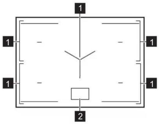
text_image
1 1 - - 1 1 - - 1 2flowchart
graph TD
    A["①"] --> B["Square"]
    C["1"] --> D["Square"]
    E["2"] --> F["Square"]
    G["3"] --> H["Square"]
    I["4"] --> J["Square"]
    K["≡"] --> L["Square"]
    M["Y"] --> N["Square"]
    O["67"] --> P["Square"]
    Q["8"] --> R["Square"]
natural_image
Two technical diagrams showing circular components inside rectangular chambers, one with a checkmark and the other with a checkmark (no text or symbols)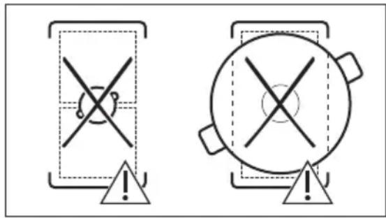
text_image
Two warning symbols: a cross symbol inside a shield and a circle with cross symbol inside a pot, both marked with an exclamation mark.6.14 FUNCTIONS: Pan-frying
natural_image
Simple line drawing of a balance scale with an arrow indicating the pointer (no text or symbols)a. Pannan er ekki rétt ef pú getur sett peninginn á milli reglustikunnar og pönnunnar.
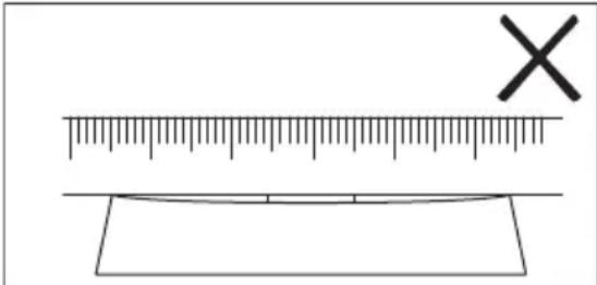
text_image
Diagram showing a ruler and a cross mark above a rectangular object, likely illustrating measurement or calibration concepts.b. Pannan er rétt ef pú getur ekki sett peninginn á milli reglustikunnar og pönnunnar.
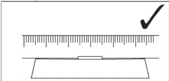
text_image
Diagram showing a ruler measuring a rectangular object with a checkmark indicating the measurement.6.15 FUNCTIONS: Boiling
6.16 FUNCTIONS: Melting
6.22 Power Management
natural_image
Pure diagram of Y-shaped structures with bidirectional arrows, no text or symbols presentnatural_image
Diagram of a smart air lift or control system with a tank, sensor, and signal icon (no text labels)
How to install your AEG Induction Hob - Worktop installation
4. IZSTRĀDĀJUMA APRAKSTS
flowchart
graph TD
    A["①"] --> B["Square"]
    C["1"] --> D["Square"]
    E["2"] --> F["Square"]
    G["3"] --> H["Square"]
    I["4"] --> J["Square"]
    K["678"] --> L["Square"]
    M["≡"] --> N["Square"]
    O["Y"] --> P["Square"]
flowchart
graph TD
    subgraph Panel_1
        A["Component 1"] --> B["Component 2"]
        C["Component 3"] --> D["Component 4"]
        E["Component 5"] --> F["Component 6"]
    end
    subgraph Panel_2
        G["Component 1"] --> H["Component 2"]
        I["Component 3"] --> J["Component 4"]
        K["Component 5"] --> L["Component 6"]
    end
    subgraph Panel_3
        M["Functional Dishes"] --> N["Functional Dishes"]
        O["Functional Dishes"] --> P["Functional Dishes"]
    end
    subgraph Panel_4
        Q["Functional Dishes"] --> R["Functional Dishes"]
        S["Functional Dishes"] --> T["Functional Dishes"]
    end
    subgraph Panel_5
        U["Functional Dishes"] --> V["Functional Dishes"]
        W["Functional Dishes"] --> X["Functional Dishes"]
    end
    subgraph Panel_6
        Y["Functional Dishes"] --> Z["Functional Dishes"]
        AA["Functional Dishes"] --> AB["Functional Dishes"]
    end
    subgraph Panel_7
        AC["Functional Dishes"] --> AD["Functional Dishes"]
        AE["Functional Dishes"] --> AF["Functional Dishes"]
    end
    subgraph Panel_8
        AG["Functional Dishes"] --> AH["Functional Dishes"]
        AI["Functional Dishes"] --> AJ["Functional Dishes"]
    end
    subgraph Panel_9
        AK["Functional Dishes"] --> AL["Functional Dishes"]
        AM["Functional Dishes"] --> AN["Functional Dishes"]
    end
Simbols Apraksts
natural_image
Two technical diagrams showing circular components inside rectangular chambers, one with a checkmark and the other with an arrow (no text or symbols)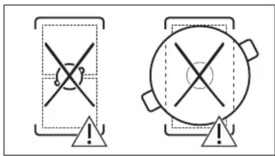
text_image
Two warning symbols: a cross symbol inside a shield and a circle with cross symbol inside a pot, both marked with an exclamation mark.natural_image
Diagram of a balance scale with an arrow indicating the pointer (no text or symbols present)text_image
Diagram showing a ruler measuring a rectangular object with a cross mark above it, likely indicating measurement or alignment.text_image
Diagram showing a ruler measuring a rectangular object with a checkmark indicating the measurement.natural_image
Pure diagram of directional arrows and symbols without any text or labelsnatural_image
Diagram of a cooking pot with a lever and Wi-Fi signal, showing no text or symbols
How to install your AEG Induction Hob - Worktop installation

4. GAMINIO APRAŠYMAS
flowchart
graph TD
    A["①"] --> B["Square"]
    C["1"] --> D["Square"]
    E["2"] --> F["Square"]
    G["3"] --> H["Square"]
    I["4"] --> J["Square"]
    K["≡"] --> L["Square"]
    M["Y"] --> N["Square"]
    O["67"] --> P["Square"]
    Q["8"] --> R["Square"]
flowchart
graph TD
    subgraph Panel_1
        A["Component 2"] --> B["Component 3"]
        C["Component 4"] --> D["Component 5"]
        E["Component 6"] --> F["Component 7"]
        G["Component 8"] --> H["Component 9"]
    end
    subgraph Panel_2
        I["Component 1"] --> J["Component 15"]
        K["Component 14"] --> L["Component 13"]
        M["Component 12"] --> N["Component 11"]
    end
    subgraph Panel_3
        O["Functional Dishes"] --> P["Functional Dishes"]
        Q["Functional Dishes"] --> R["Functional Dishes"]
        S["Functional Dishes"] --> T["Functional Dishes"]
    end
    subgraph Panel_4
        U["Functional Dishes"] --> V["Functional Dishes"]
        W["Functional Dishes"] --> X["Functional Dishes"]
        Y["Functional Dishes"] --> Z["Functional Dishes"]
    end
    subgraph Panel_5
        AA["Functional Dishes"] --> AB["Functional Dishes"]
        AC["Functional Dishes"] --> AD["Functional Dishes"]
        AE["Functional Dishes"] --> AF["Functional Dishes"]
        AG["Functional Dishes"] --> AH["Functional Dishes"]
    end
    subgraph Panel_6
        AI["Functional Dishes"] --> AJ["Functional Dishes"]
        AK["Functional Dishes"] --> AL["Functional Dishes"]
        AM["Functional Dishes"] --> AN["Functional Dishes"]
        AO["Functional Dishes"] --> AP["Functional Dishes"]
    end
    subgraph Panel_7
        AQ["Functional Dishes"] --> AR["Functional Dishes"]
        AS["Functional Dishes"] --> AT["Functional Dishes"]
        AU["Functional Dishes"] --> AV["Functional Dishes"]
        AW["Functional Dishes"] --> AX["Functional Dishes"]
    end
    subgraph Panel_8
        AZ["Functional Dishes"] --> BA["Functional Dishes"]
        BB["Functional Dishes"] --> BC["Functional Dishes"]
        BD["Functional Dishes"] --> BE["Functional Dishes"]
        BF["Functional Dishes"] --> BG["Functional Dishes"]
    end
    subgraph Panel_9
        BH["Functional Dishes"] --> BI["Functional Dishes"]
        BJ["Functional Dishes"] --> BK["Functional Dishes"]
        BL["Functional Dishes"] --> BM["Functional Dishes"]
        BN["Functional Dishes"] --> BO["Functional Dishes"]
    end
Simbolis Aprašymas
1

flowchart
graph TD
    A["Screen Screen"] --> B["Keyboard"]
    B --> C["Keyboard"]
    C --> D["Keyboard"]
    D --> E["Keyboard"]
    E --> F["Auto Level1"]
    F --> G["Manual"]
    G --> H["Hand Icon"]
    H --> I["Arrow to Button"]
    I --> J["Arrow to Left"]
    J --> K["Arrow to Right"]
natural_image
Two technical diagrams showing circular components inside rectangular chambers, one with a checkmark and the other with an arrow (no text or symbols)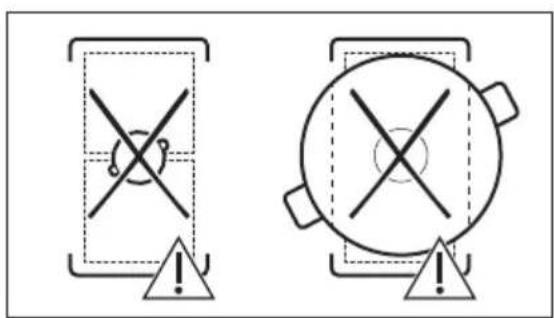
text_image
Two warning symbols: a triangular warning box with cross and warning symbol, and a circular warning box with cross and warning symbol.natural_image
Diagram of a balance scale with an arrow indicating force direction (no text or symbols)text_image
Diagram showing a ruler measuring a rectangular object with a cross mark symbol, likely illustrating a measurement or calibration concept.text_image
Diagram showing a ruler measuring a surface with a checkmark indicating the correct measurement.6.15 FUNKCIJOS: Virimas
natural_image
Pure diagram of Y-shaped structures with bidirectional arrows, no text or symbols presentnatural_image
Diagram of a portable room with a lid and antenna, showing signal transmission and wireless signal (no text or symbols)8. PRIEŽIŪRA IR VALYMAS
⚠️ ISPÉJIMAS!
Žr. saugos skyrius.

How to install your AEG Induction Hob - Worktop installation
4. ОПИС НА ПРОИЗВОДОТ
flowchart
graph TD
    A["①"] --> B["Square"]
    C["1"] --> D["Square"]
    E["2"] --> F["Square"]
    G["3"] --> H["Square"]
    I["4"] --> J["Square"]
    K["678"] --> L["Square"]
    M["≡"] --> N["Square"]
    O["Y"] --> P["Square"]
    Q["●"] --> R["Square"]
    S["●"] --> T["Square"]
flowchart
graph TD
    subgraph Panel 1
        A["Component 1"] --> B["Component 2"]
        C["Component 3"] --> D["Component 4"]
        E["Component 5"] --> F["Component 6"]
        G["Component 7"] --> H["Component 8"]
        I["Component 9"] --> J["Component 10"]
    end
    subgraph Panel 2
        K["Component 1"] --> L["Component 2"]
        M["Component 3"] --> N["Component 4"]
        O["Component 5"] --> P["Component 6"]
        Q["Component 7"] --> R["Component 8"]
        S["Component 9"] --> T["Component 10"]
    end
    subgraph Panel 3
        U["Functional Dishes"] --> V["Functional Dishes"]
        W["Functional Dishes"] --> X["Functional Dishes"]
        Y["Functional Dishes"] --> Z["Functional Dishes"]
    end
    subgraph Panel 4
        AA["Functional Dishes"] --> AB["Functional Dishes"]
        AC["Functional Dishes"] --> AD["Functional Dishes"]
        AE["Functional Dishes"] --> AF["Functional Dishes"]
    end
    subgraph Panel 5
        AG["Functional Dishes"] --> AH["Functional Dishes"]
        AI["Functional Dishes"] --> AJ["Functional Dishes"]
        AK["Functional Dishes"] --> AL["Functional Dishes"]
    end
    subgraph Panel 6
        AM["Functional Dishes"] --> AN["Functional Dishes"]
        AO["Functional Dishes"] --> AP["Functional Dishes"]
        AQ["Functional Dishes"] --> AR["Functional Dishes"]
    end
    subgraph Panel 7
        AS["Functional Dishes"] --> AT["Functional Dishes"]
        AU["Functional Dishes"] --> AV["Functional Dishes"]
        AW["Functional Dishes"] --> AX["Functional Dishes"]
    end
    subgraph Panel 8
        AY["Functional Dishes"] --> AZ["Functional Dishes"]
        BA["Functional Dishes"] --> BB["Functional Dishes"]
        BC["Functional Dishes"] --> BD["Functional Dishes"]
    end
    subgraph Panel 9
        BE["Functional Dishes"] --> BF["Functional Dishes"]
        BG["Functional Dishes"] --> BH["Functional Dishes"]
        BI["Functional Dishes"] --> BJ["Functional Dishes"]
    end
Симбол Опис
1

natural_image
Two technical diagrams showing circular components inside rectangular chambers, one with a checkmark and the other with an arrow (no text or symbols)
text_image
Two warning symbols: a cross symbol on a device and a circle with cross on a pot, both marked with an exclamation mark.natural_image
Diagram of a balance scale with an arrow indicating direction (no text or symbols present)text_image
Diagram showing a ruler measuring a rectangular object with a cross mark, likely illustrating measurement or calibration concept.text_image
Diagram showing a ruler measuring a rectangular object with a checkmark indicating the measurement.natural_image
Pure diagram of directional arrows and symbols without any text or labelsnatural_image
Diagram of a smart heating setup with a pot, antenna, and wireless signal icon (no text or symbols)
How to install your AEG Induction Hob - Worktop installation
4. PRODUKTBESKRIVELSE
natural_image
Two technical diagrams showing circular components inside rectangular chambers, one with a checkmark and the other with an arrow (no text or symbols)
text_image
Two warning symbols: a cross symbol inside a container and a circle with cross inside a pot, both marked with an exclamation mark.natural_image
Diagram of a balance scale with an arrow indicating the pointer (no text or symbols present)a. Pannen er feil hvis du kan legge mynten mellom linjalen og pannen.
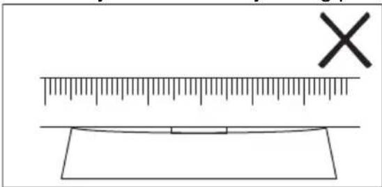
text_image
Diagram showing a ruler measuring a rectangular object with a cross mark symbol, likely illustrating a measurement or calibration concept.text_image
Diagram showing a ruler measuring a rectangular object with a checkmark indicating the measurement point.6.15 FUNKSJONER: Kokende
natural_image
Pure diagram of directional arrows and symbols without any text or labelsnatural_image
Diagram of a portable kitchen with a cooking pot and antenna, showing signal waves and an arrow (no text or symbols)8. STELL OG RENGJ∅RING

ADVARSEL!
How to install your AEG Induction Hob - Worktop installation
4. OPIS URZĄDZENIA
flowchart
graph TD
    A["①"] --> B["Square"]
    C["1"] --> D["Square"]
    E["2"] --> F["Square"]
    G["3"] --> H["Square"]
    I["4"] --> J["Square"]
    K["678"] --> L["Square"]
    M["≡"] --> N["Square"]
    O["Y"] --> P["Square"]
    Q["●"] --> R["Square"]
    S["●"] --> T["Square"]
flowchart
graph TD
    subgraph Panel 1
        A["Component 1"] --> B["Component 2"]
        C["Component 3"] --> D["Component 4"]
        E["Component 5"] --> F["Component 6"]
        G["Component 7"] --> H["Component 8"]
        I["Component 9"] --> J["Component 10"]
    end
    subgraph Panel 2
        K["Component 1"] --> L["Component 2"]
        M["Component 3"] --> N["Component 4"]
        O["Component 5"] --> P["Component 6"]
        Q["Component 7"] --> R["Component 8"]
        S["Component 9"] --> T["Component 10"]
    end
    subgraph Panel 3
        U["Functional Dishes"] --> V["Functional Dishes"]
        W["Functional Dishes"] --> X["Functional Dishes"]
        Y["Functional Dishes"] --> Z["Functional Dishes"]
    end
    subgraph Panel 4
        AA["Functional Dishes"] --> AB["Functional Dishes"]
        AC["Functional Dishes"] --> AD["Functional Dishes"]
        AE["Functional Dishes"] --> AF["Functional Dishes"]
    end
    subgraph Panel 5
        AG["Functional Dishes"] --> AH["Functional Dishes"]
        AI["Functional Dishes"] --> AJ["Functional Dishes"]
        AK["Functional Dishes"] --> AL["Functional Dishes"]
    end
    subgraph Panel 6
        AM["Functional Dishes"] --> AN["Functional Dishes"]
        AO["Functional Dishes"] --> AP["Functional Dishes"]
        AQ["Functional Dishes"] --> AR["Functional Dishes"]
    end
    subgraph Panel 7
        AS["Functional Dishes"] --> AT["Functional Dishes"]
        AU["Functional Dishes"] --> AV["Functional Dishes"]
        AW["Functional Dishes"] --> AX["Functional Dishes"]
    end
    subgraph Panel 8
        AY["Functional Dishes"] --> AZ["Functional Dishes"]
        BA["Functional Dishes"] --> BB["Functional Dishes"]
        BC["Functional Dishes"] --> BD["Functional Dishes"]
    end
    subgraph Panel 9
        BE["Functional Dishes"] --> BF["Functional Dishes"]
        BG["Functional Dishes"] --> BH["Functional Dishes"]
        BI["Functional Dishes"] --> BJ["Functional Dishes"]
    end
Symbol Opis
1

natural_image
Two technical diagrams showing circular components inside rectangular chambers, one with a checkmark and the other with an arrow (no text or symbols)
text_image
Two safety warning symbols: a cross symbol inside a shield and a circle with cross symbol inside a pot, both marked with an exclamation mark.natural_image
Diagram of a balance scale with an arrow indicating direction (no text or symbols present)text_image
Diagram showing a ruler measuring a rectangular object with a cross mark symbol, likely illustrating a measurement or calibration concept.text_image
Diagram showing a ruler measuring a rectangular object with a checkmark indicating the measurement.natural_image
Pure diagram of Y-shaped structures with bidirectional arrows, no text or symbols presentnatural_image
Diagram of a roof-mounted device with a sloped roof and a pot, showing signal transmission and wireless signal (no text or symbols)i
How to install your AEG Induction Hob - Worktop installation
6.4 Utilizar as zonas de cozedura
natural_image
Two technical diagrams showing circular components inside rectangular chambers, one with a checkmark and the other with an arrow (no text or symbols)
text_image
Two warning symbols: a cross symbol inside a container and a circle with cross symbol inside a pot, both marked with an exclamation mark.natural_image
Diagram of a balance scale with an object on one side and an arrow indicating direction (no text or symbols)a. A panela está incorreta se conseguir colocar a moeda entre a régua e a panela.

text_image
Diagram showing a ruler measuring a rectangular object with a cross mark symbol, likely illustrating a measurement or calibration concept.text_image
Diagram showing a ruler measuring a rectangular object with a checkmark indicating the measurement.6.15 UNÇÕES: Ferver
natural_image
Pure diagram of Y-shaped structures with bidirectional arrows, no text or symbols presentnatural_image
Diagram of a cooking pot with a diagonal pole and a Wi-Fi signal icon, no text or symbols present
How to install your AEG Induction Hob - Worktop installation
4. ОПИС ПРОИЗВОДА
flowchart
graph TD
    A["①"] --> B["Square"]
    C["1"] --> D["Square"]
    E["2"] --> F["Square"]
    G["3"] --> H["Square"]
    I["4"] --> J["Square"]
    K["678"] --> L["Square"]
    M["≡"] --> N["Square"]
    O["Y"] --> P["Square"]
    Q["●"] --> R["Square"]
    S["●"] --> T["Square"]
natural_image
Two technical diagrams showing a vertical panel with circular elements and a horizontal oval component, both without any text or symbols.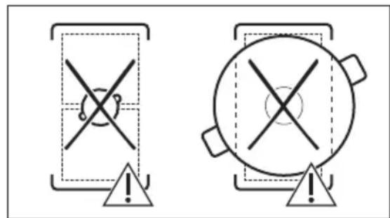
text_image
Two warning symbols: a cross symbol with a minus sign inside a rectangular frame and an exclamation mark, and a circle with an exclamation mark inside a circular container.natural_image
Diagram of a balance scale with a ruler and pointer, no text or symbols presenttext_image
Diagram showing a ruler measuring a rectangular object with a cross mark symbol, likely illustrating a measurement or calibration concept.text_image
Diagram showing a ruler measuring a rectangular object with a checkmark indicating the measurement.natural_image
Pure diagram of directional arrows and a Y-shaped symbol without any text or labelstext_image
Diagram illustrating a smart home control system with a pot, signal wave, and wireless signal detection
How to install your AEG Induction Hob - Worktop installation

4. POPIS VÝROBKU
natural_image
Two technical diagrams showing circular components inside square chambers, one with a checkmark and the other with a checkmark (no text or symbols)
text_image
Two warning symbols: a cross symbol inside a rectangular frame and a circle with cross symbol inside a larger circle, both marked with an exclamation mark.natural_image
Diagram of a balance scale with a ruler and pointer, no text or symbols presenttext_image
Diagram showing a ruler with an 'X' mark above it and a blank rectangular object below, likely for measuring or calibration purposes.text_image
Diagram showing a ruler measuring a rectangular object with a checkmark indicating the measurement.6.15 FUNKCIE: Varenie
natural_image
Pure diagram of directional arrows and symbols without any text or labelsnatural_image
Diagram of a smart air lift with a pot and signal icons, no text or symbols present
Okienko komunikátora infračerveného signálu Hob²Hood udržiavajte čisté.

N Modra in modra N Modra in modra N Modra in modra
L1 Črna L1 Črna L Črna in rjava
L2 Rjava L2 Rjava
3.4 Montaža
How to install your AEG Induction Hob - Worktop installation

4. OPIS IZDELKA
4.1 Postavitev kuhalne površine

text_image
1 1 - - 1 1 - - 1 2flowchart
graph TD
    A["①"] --> B["Square"]
    C["1"] --> D["Square"]
    E["2"] --> F["Square"]
    G["3"] --> H["Square"]
    I["4"] --> J["Square"]
    K["678"] --> L["Square"]
    M["≡"] --> N["Square"]
    O["Y"] --> P["Square"]
natural_image
Two technical diagrams showing circular components inside rectangular chambers, one with a checkmark and the other with an arrow (no text or symbols)
text_image
Two warning symbols: a cross symbol inside a rectangular frame and a circle with cross on top, both marked with an exclamation mark.natural_image
Diagram of a balance scale with an arrow indicating the pointer (no text or symbols present)text_image
Diagram showing a ruler measuring a surface with an 'X' mark and a blank rectangular object below, likely for geometric or measurement purposes.b. Ponev je prava, če med ravnilo in ponvo ne morete postaviti kovanca.

text_image
Diagram showing a ruler measuring a rectangular object with a checkmark indicating the measurement.6.15 FUNKCIJE: Kuhanje
natural_image
Pure diagram of directional arrows and symbols without any text or labelsnatural_image
Diagram of a simple electrical circuit with a pot, wires, and an antenna (no text or symbols)8. VZDRŽEVANJE IN ČIŠČENJE

OPOZORILO!
How to install your AEG Induction Hob - Worktop installation

flowchart
graph TD
    A["①"] --> B["Square"]
    C["1"] --> D["Square"]
    E["2"] --> F["Square"]
    G["3"] --> H["Square"]
    I["4"] --> J["Square"]
    K["≡"] --> L["Square"]
    M["Y"] --> N["Square"]
    O["67"] --> P["Square"]
    Q["8"] --> R["Square"]
flowchart
graph TD
    A["Screen Screen"] --> B["Keyboard"]
    B --> C["Keyboard"]
    C --> D["Keyboard"]
    D --> E["Keyboard"]
    E --> F["Auto Level1"]
    F --> G["Manual"]
    G --> H["Hand Icon"]
    H --> I["Arrow to Button"]
    I --> J["Arrow to Left"]
    J --> K["Arrow to Right"]
natural_image
Two technical diagrams showing circular components inside rectangular chambers, one with a checkmark and the other with an arrow (no text or symbols)
text_image
Two warning symbols: a cross symbol with a minus sign inside a rectangular frame and an exclamation mark in the circle, both pointing to a triangle.natural_image
Diagram of a balance scale with an arrow indicating the pointer (no text or symbols present)text_image
Diagram showing a ruler measuring a surface with a cross mark symbol, likely illustrating a measurement or calibration concept.text_image
Diagram showing a ruler measuring a rectangular object with a checkmark indicating the measurement.6.15 FUNCIONES: Hervir
natural_image
Pure diagram of directional arrows and a Y-shaped symbol without any text or labelsnatural_image
Diagram of a cooking pot with a lever and signal icon, no text or symbols present
How to install your AEG Induction Hob - Worktop installation
4. PRODUKTBESKRIVNING
4.1 Hällens layout
text_image
1 1 - - 1 1 - - 1 21 Induktion tillagningszon
2 Kontrollpanel
i
flowchart
graph TD
    A["①"] --> B["Square"]
    C["1"] --> D["Square"]
    E["2"] --> F["Square"]
    G["3"] --> H["Square"]
    I["4"] --> J["Square"]
    K["678"] --> L["Square"]
    M["≡"] --> N["Square"]
    O["Y"] --> P["Square"]
    Q["●"] --> R["Square"]
    S["●"] --> T["Square"]
natural_image
Two technical diagrams showing circular components inside rectangular chambers, one with a checkmark and the other with a checkmark (no text or symbols)
text_image
Two warning symbols: a cross symbol inside a triangular frame and a circle with cross inside a pot, both marked with an exclamation mark.natural_image
Diagram of a balance scale with an arrow indicating force direction (no text or symbols)text_image
Diagram showing a ruler and a rectangular object with an 'X' mark, likely illustrating a measurement or calibration concept.text_image
Diagram showing a ruler measuring a rectangular object with a checkmark indicating the measurement.6.15 FUNKTIONER: Koka
natural_image
Pure diagram of directional arrows and symbols without any text or labelsnatural_image
Diagram of a cooking pot with a lever and sensor signal, no text or symbols present