Snipe Dome - Receiver Selfsat - Free user manual and instructions
Find the device manual for free Snipe Dome Selfsat in PDF.

User questions about Snipe Dome Selfsat
0 question about this device. Answer the ones you know or ask your own.
Ask a new question about this device
Download the instructions for your Receiver in PDF format for free! Find your manual Snipe Dome - Selfsat and take your electronic device back in hand. On this page are published all the documents necessary for the use of your device. Snipe Dome by Selfsat.
USER MANUAL Snipe Dome Selfsat
natural_image
Abstract curved graphic with orange, gray, and black segments on white background (no text or symbols)SNIPE DOME
I DO IT CO., LTD
1637, Smart-Hub Industry-University Convergence Center, 237 Sangidaehak-ro, Silheung-si, Gyeonggi-do, Korea (429-793)
TEL +82 (0)31 8041 1500 FAX +82 (0)31 8041 1550 E-MAIL sales@selfsat.com WEB www.selfsat.com
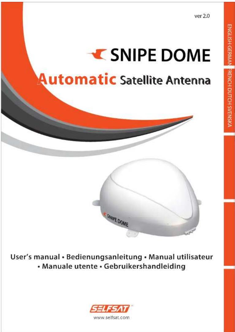
ver 2.0
SNIPE DOME
Automatic Satellite Antenna
natural_image
White dome-shaped object with 'SNIPEDOME' branding on the side (no other text or symbols visible)User's manual • Bedienungsanleitung • Manual utilisateur • Manuale utente • Gebruikershandleiding
SELFSAT
www.selfsat.com
Contents
1. General Information
1-1. Introduction 3
1-2. Proper use and Operation 4
1-3. Safety Notes 5
2. Contents
2-1. Components Bundle 6
2-2. Name of parts 7
3. Operating Instruction
3-1. Connection Diagram 8
3-2. Functional Description 9
3-3. Quick Reference 11
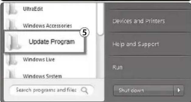
4. Program update
4-1. Connection Diagram for updating 11
4-2. Update Process 12
5. Trouble Shooting
Trouble Shooting 5-6.
6. Specifications
6-1. Dimension 17
6-2. Specifications 17
7. Camping Car Installation
7-1. Required space for the SNIPE DOME 18
7-2. Equipment for Installation 19
1. General Information
1-1. Introduction
These instructions describe the functions and operation of the SNIPE DOME satellite system. Correct and safe operation of the system can only be ensured by following these instructions.
Your SNIPE DOME is an intelligent satellite TV reception antenna system which can align itself towards a preset satellite automatically as long as the system is located within the footprint of this satellite.
The SNIPE DOME only occupies requisite space while it performs the necessary adjustments with the slim and agile antenna body.
For general operation, please ensure that the system always has a clear view to the sky. If the satellite's signal beam is interrupted by obstacles such as mountains, buildings or trees, the unit will not function and no TV signal will be received
The first few pages of these instructions contain information about using the general functions of your SNIPE DOME, followed by an explanation of all the adjustment options. The last pages of the instructions cover various technical aspects of the SNIPE DOME.
natural_image
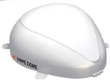
3D rendered white plastic object with rounded top and side features (no text or symbols)1-2. Proper use and operation
This product has been designed for fixed installation on vehicles with maximum speeds of 130 km/h. It is designed to automatically aim an antenna at geostationary television satellites. The power to the system is supplied by a standard vehicle electrical system with a rated voltage of 12 or 24 Volts DC.
Use of the equipment for any other purpose to the one specified is not permitted.
Please also note the following instructions from the manufacturer :
- It is not permitted to change the overall device by removing or adding individual components.
- The use of any other components to those originally installed is not permissible.
- Installation must only be performed by sufficiently qualified personnel. All instructions in the supplied Installation Instructions, which is separately provided, must be carefully followed.
- The product does not require any regular maintenance. Housings and enclosures must not be opened. Check and maintenance work should always be carried out by a qualified specialist.
- All of the relevant and approved guidelines of the automotive industry must be observed and complied with.
- The equipment must only be installed on hard vehicle roofs.
- Avoid to clean your vehicle with the mounted satellite system in a single-bay or drive-through car wash or with a high-pressure cleaner.
1-3. Safety Notes

In order to ensure that your SNIPE DOME works properly you must ensure that it is following by the Operating Instructions in this manual and used as intended purpose.
When it is correctly installed, the antenna automatically assumes the rest position when the ignition is switched on and locks itself. If the system cannot fully be removed due to user's negligence, then it is your responsibility to check that the antenna is properly stored in safe.
Please also note that different legal requirements are applied to the operation of electrical and electronic equipment in different countries. As the user of this equipment, you are responsible for yourself ensuring compliance with the relevant laws and regulations. The manufacturer does not take liability for direct or indirect consequential damage of the system, motor vehicles or other equipments by reason of unsuitable battery usage or erroneous installation or wrong wire connection.
2. Contents
2-1. Components Bundle
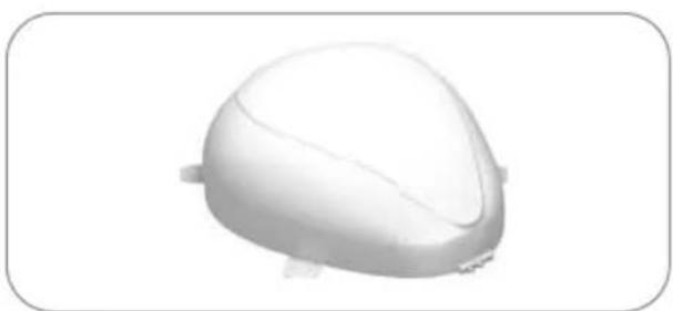
natural_image
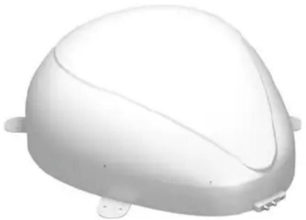
3D rendered white dome-shaped object with rounded edges and small protrusions (no text or symbols)Main unit
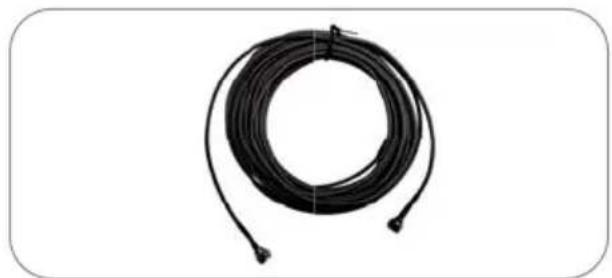
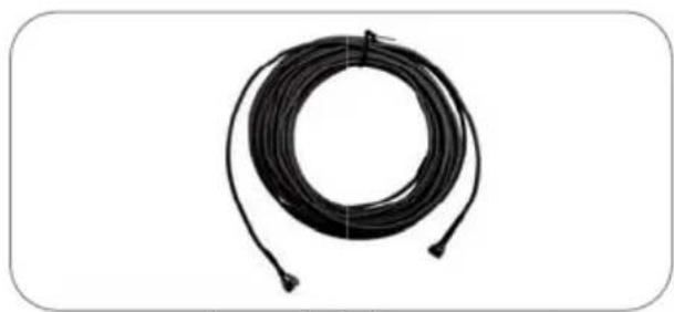
natural_image
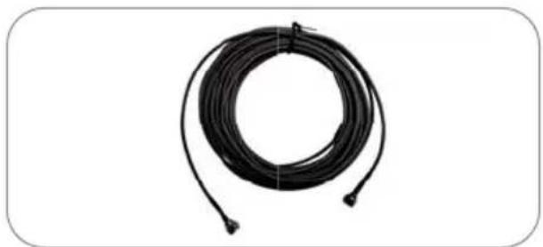
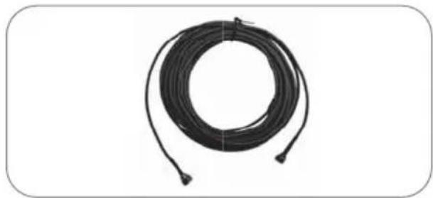
Coiled black cable or wire with connectors, isolated on white background (no text or symbols)Controller Cable (12m-Black color)
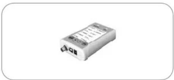
natural_image
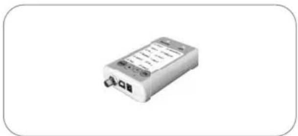
Exterior view of a battery pack (no visible text or symbols)Controller

natural_image
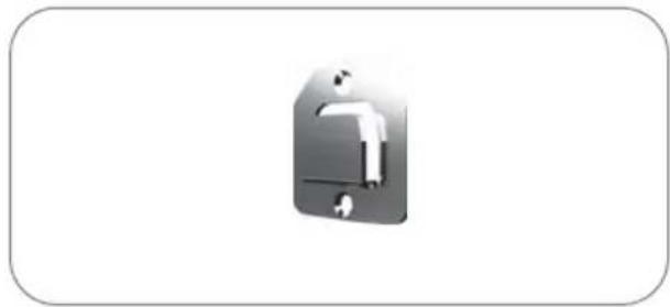
Simple 3D icon of a computer mouse inside a rounded rectangle (no text or symbols)Controller bracket
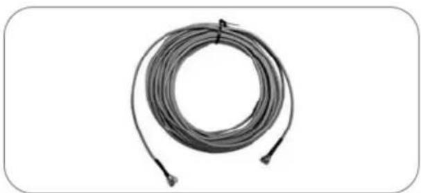
natural_image
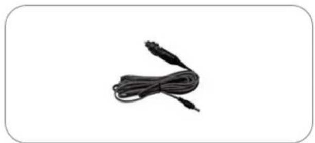
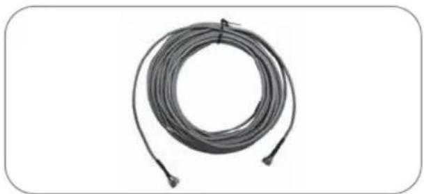
Coiled cable or wire with connectors, no visible text or symbolsReceiver cable (12m - Grey color)
natural_image
Black cable with two connectors, isolated on white background (no text or symbols)Cigar jack adaptor
natural_image
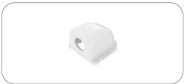
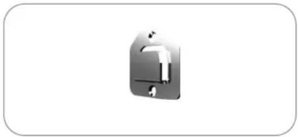
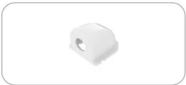
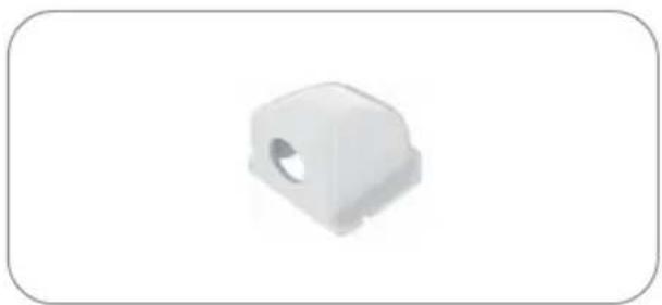
White plastic mechanical component with a circular hole, shown against a plain white background (no text or symbols)Cable holder
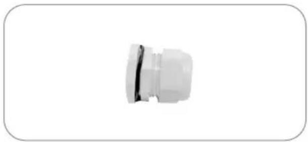
natural_image
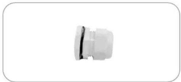
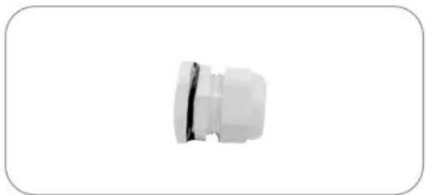
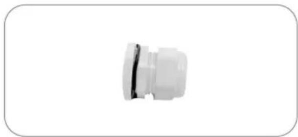
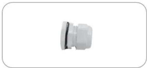
Close-up of a white plastic connector or fitting with a black seam, isolated on white background (no text or symbols)Cable gland
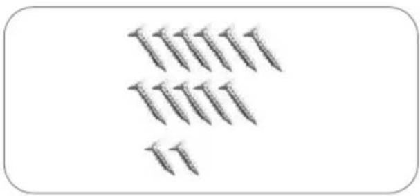
natural_image
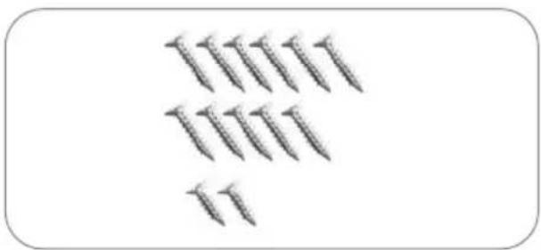
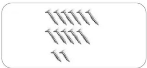
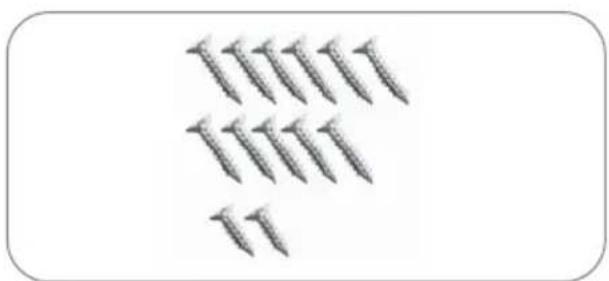
Group of screws arranged in two rows, no text or symbols presentScrews M4x20(11), M4x16(2)
User manual
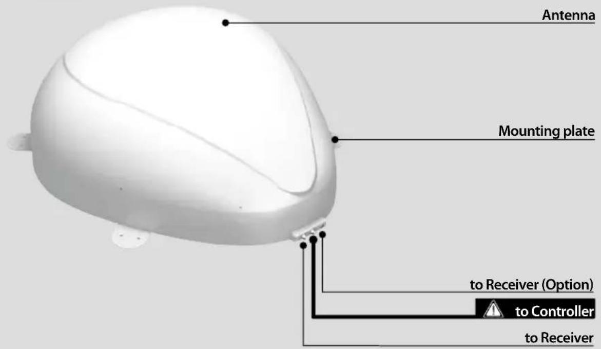
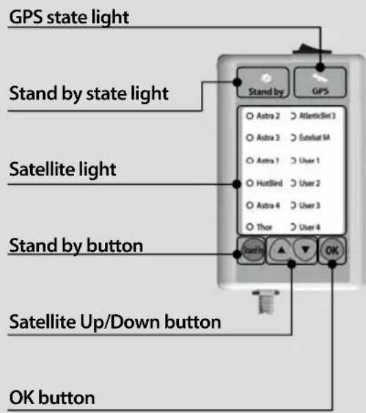
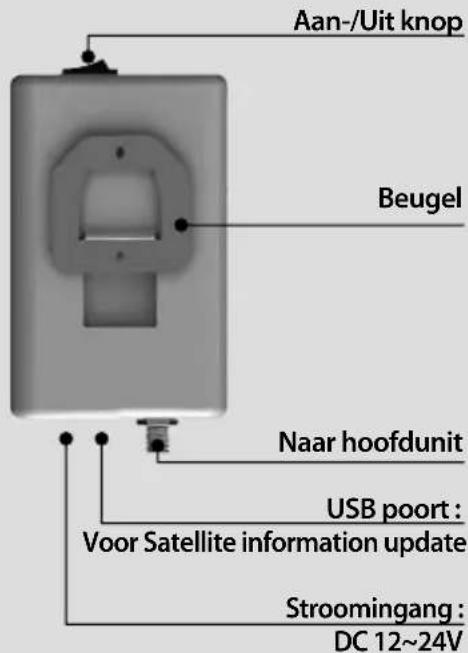
2-2. Name of parts
Main unit
Controller
3. Operating Instruction
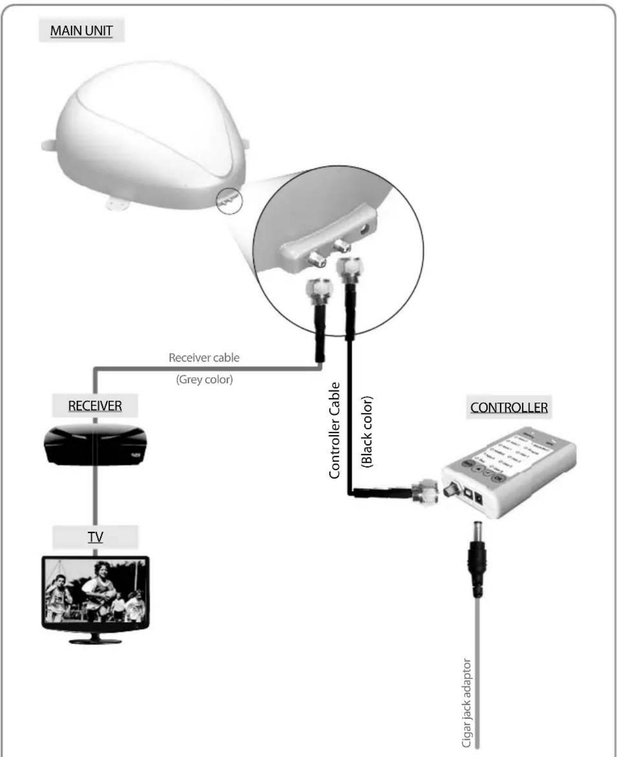
3-1. Connection Diagram
flowchart
graph TD
    A["MAIN UNIT"] --> B["Receiver"]
    B --> C["TV"]
    C --> D["TV"]
    D --> E["Controller Cable (Grey color)"]
    E --> F["Controller Cable (Black color)"]
    F --> G["Cigar jack adaptor"]
Use the controller cable to connect between the controller and antenna. The controller cable looks similar to the antenna receiver cable but you can distinguish them by the color and labeling.
3-2. Functional Description
A. Power On
| Function Description | Operation | |
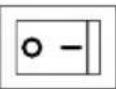 | "Power" Switch | i. When the all cable connections are completed, switch on with the "Power Switch" button on the top of the controller. |
 | "Stand by" Light Solid ON | ii. If the position of antenna was in Basic position, "STAND BY state light" will be solid on to show it is STAND BY to use. |
 | 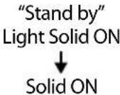 | iii. If the position of antenna was not in the Basic position, "STAND BY state light" will flash, and the antenna will return to the Basic position within a maximum 2 minutes. Then "STAND BY state light" will be solid on. |
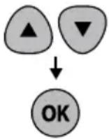
B. Selecting the satellite
| Function Description Operation | |
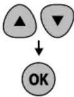 | “Satellite Up / Down button” Light↓“OK” Button |
C. Searching the satellite
| Function Description | Operation | |
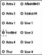 | “Satellite” light | i. After the satellite selection, “Stand by State” light will go off and the LED light of the selected satellite will start flashing. |
| ii. Once selected satellite has been found, the LED light of the satellite will become solid. | ||
D. Changing the satellite
| Function Description Operation | |
 | “SatelliteUp / Down button” Light↓“OK” Button |
E. Back to Basic position
| Function Description Operation | ||
 | “Stand by” Button | i. Whenever you wish to return the antenna back to the Basic position, press and hold the “STAND BY” button for a few seconds. |
F. GPS LED light
| Function Description | Operation |
 | “GPS” light |
3-3. Quick Reference
| Classification | Description |
| Operating (Searching the satellite) | 1. Switch on with the “Power switch” button on the top of the controller.2. Upon power on, all LED will flash twice.3. Wait until “Stand by State” light & one “Satellite LED” light, which you set previously or the first satellite in the controller, remain solid on.4. Select the desired satellite using the “UP/DOWN” buttons, then press the “OK” button to select.5. The satellite LED light will start to flash, wait until it stays solid on.6. When the satellite LED light stays solid on, the selected satellite has been located and a signal can be seen on the satellite TV. |
4. Program update
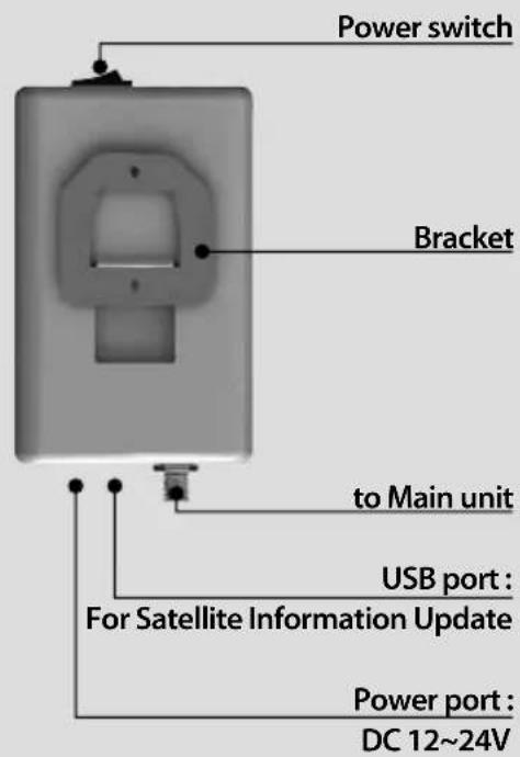
4-1. Connection Diagram for updating
※ Searching program with targeting satellites is pre-programmed. If there is no problem to search the satellites, do not need below update process.
"USB port is used for Satellite Information Update only"
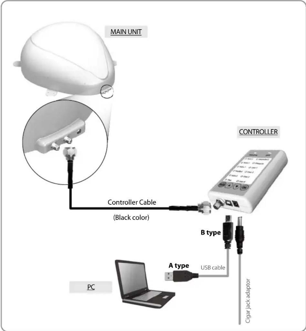
Simply connect the Controller to PC using USB cable. USB cable is not included in the package.
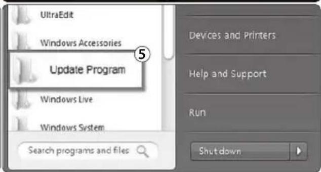
4-2. Update Process
Using SNIPE DOME Update Program, refresh the satellite date of your SNIPE DOME.
i. Please connect the main unit – controller – PC
ii. Download the update program on our website (http://www.selfsat.com) as the following instruction.
- Click [S/W update] of the model you want to update and download the update program.
- Download the satellite information.
(Make sure you check the product model and the region, and download the correct satellite information)
- Download the USB Serial Driver File.
Install [USB Serial Drive]iii.
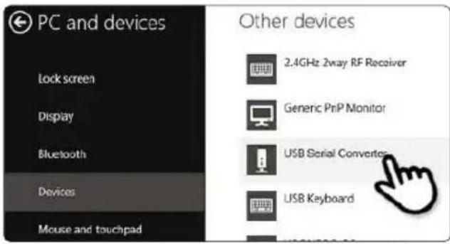
- Connect the USB cable and turn on the controller. Please check [USB Serial Converter] port has been activated on [PC and devices].
- When everything is connected properly and the controller is turned on, but if [USB Serial Converter] is still not activated, please download the USB Driver attached on the home page.
Installationiv.
-
Please download the SNIPE DOME update program.
-
Unzip [update program].
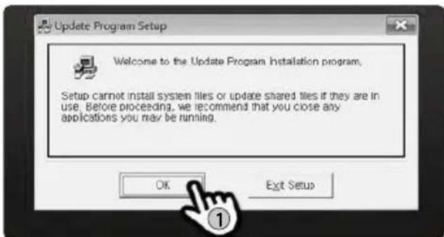
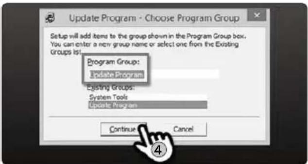
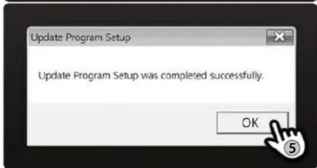
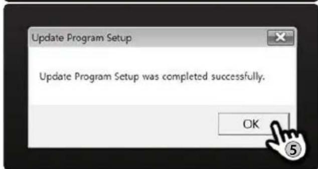
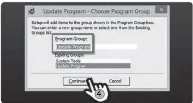
- Open [setup.exe] and do as the following pictures.
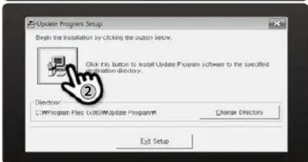

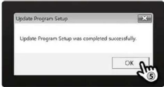
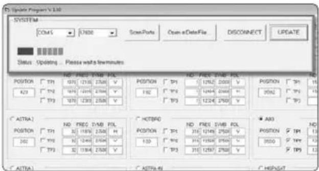
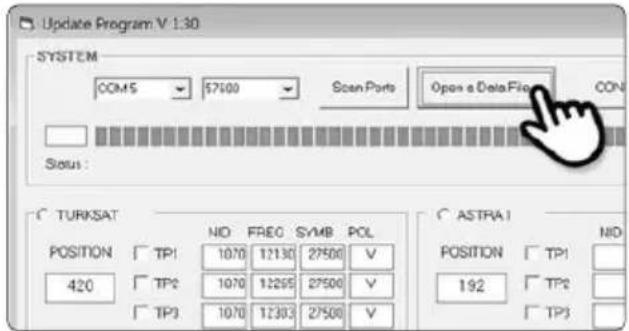
Proceeding Updatev.
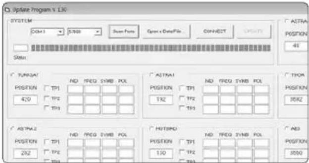
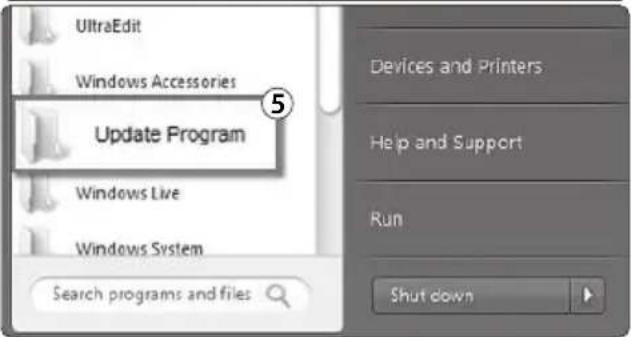
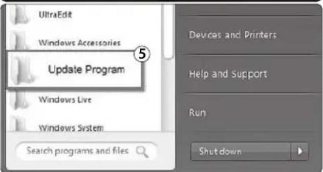
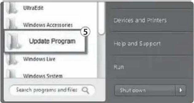
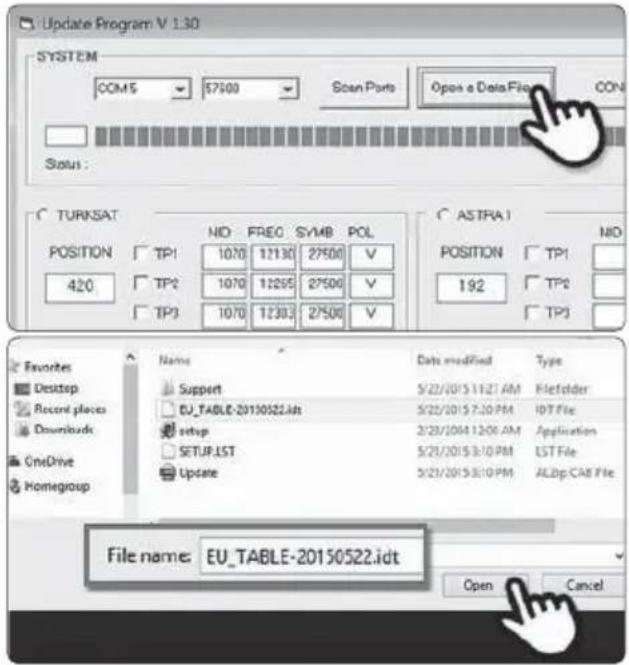
- Open the installed update program and you will see the screen.
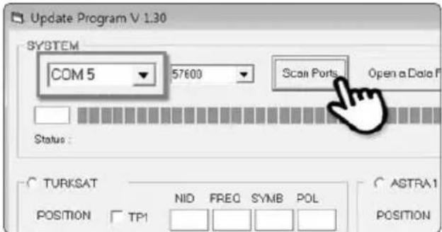
- Turn on the controller and click [Scan Ports]. The Port name might be different depending on the PC models.

NOTE
If you see [Invalid port] message after clicking [scan ports], please check if you selected the correct port, and if you see [Invalid port] message even if you chose the correct one, please change the setting as below; you do not need to follow until 5-3 if you do not see [Invalid port] message.
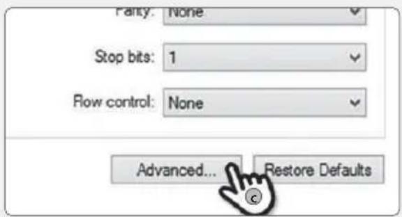
02-a. Click the com port on the [Device manager] and click properties.
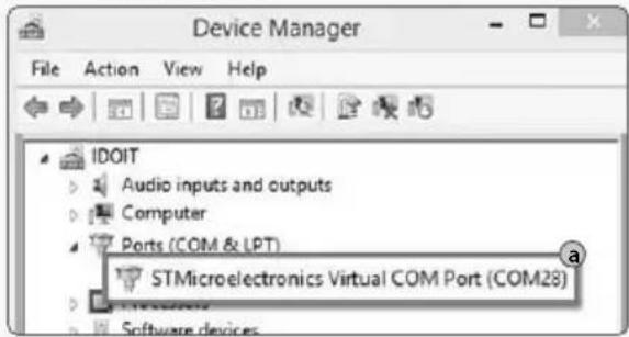
02-c. Go to [Advanced...]
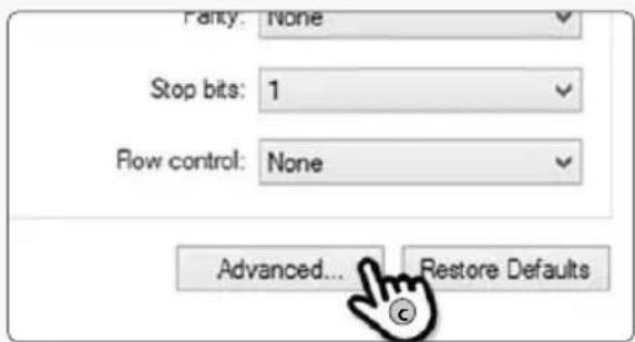
02-b. Go to [Port Settings]
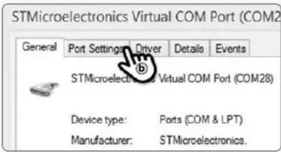
02-d. Change the COM Port Number to one of the low numbers and select [OK].

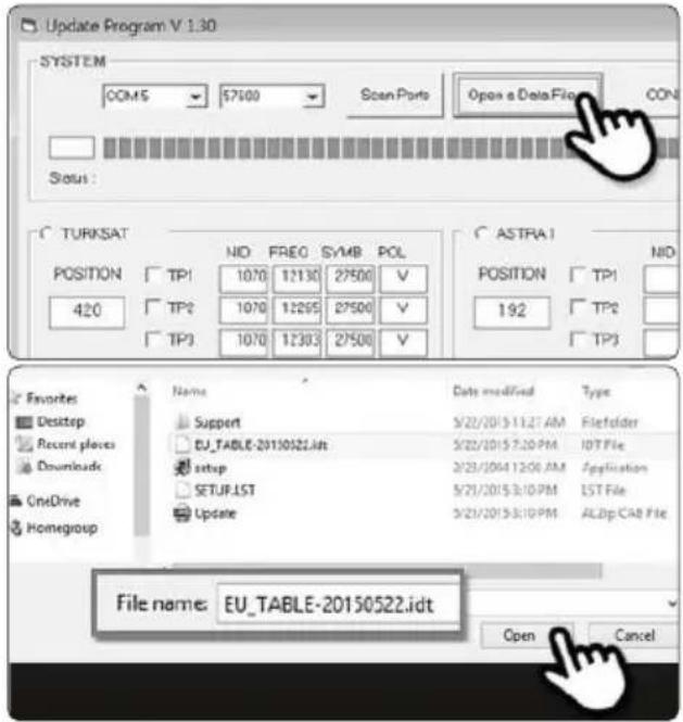
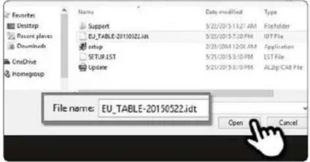
Open the data file(*.idt) as the pictures. 03.
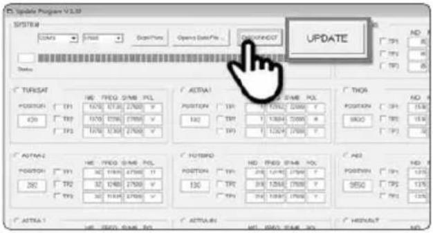
- Click [Connect] button and check [update] button has been activated as the following picture.
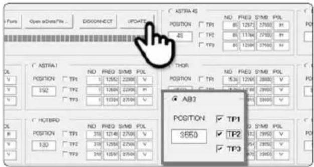
- Check the satellite and TP to update, and click [UPDATE].

NOTE
At lease 1 TP should be selected for updating. Satellite should be updated one by one.
- he update process will be indicated as the picture.

NOTE
The GPS LED will be blinking while updating. (If the update is not going correctly, the LED will not be blinking. In this case, please check if all the cables for main unit - controller - PC are all correctly connected and the controller Led is turned on)
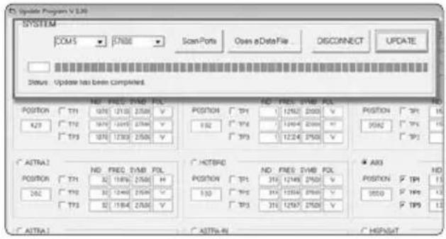
Check [Update has been completed].07.

NOTE
In case the controller power was turned off or cable was disconnected or any of such things happened to stop the process while updating, please proceed the update process from the first again.
If you would like to update other satellites too, please check the satellite you want and do the same.08.

NOTE
You can also proceed the update manually, by changing the values arbitrarily on the screen.
If you put incorrect data, ERROR message will be shown.
- Please read the ERROR message and correct the information as the instruction.
- If you had put correct information and if [Data Format ERROR] is keep shown, please put different data or contact service@selfsat.com.
vi. Lastly, operate the SNIPE DOME and see if it searches the updated satellite properly.
If SNIPE DOME still cannot search the satellite even after the update was completed, please try updating again, or contact service@selfsat.com.

NOTE
Do not turn off the power or disconnect the cable before update procedure is completed.
How to update satellite information can be changed by reflecting the newest satellite information.
Please make sure to get how to update the product through our web site (www.selfsat.com)
5. Trouble shooting
There are a number of common issues that can affect the signal reception quality or the operation of the SNIPE DOME. The following sections address these issues and potential solutions.
A. No function when you power on the Controller
i. Check again all the cable connections have been made correctly.
√ Connection between the power and controller
√ Connection between the controller and the antenna.
Make sure that the right port of the antenna should be connected to the controller.
Check if the power input cable has been damaged.ii.
B. Fail to search the selected satellite
i. Satellite signals can be blocked or degraded by buildings, trees.
Make sure there are no obstructions in a southward direction.
ii. Check your program of Controller often, and get the latest updates for your SNIPE DOME.
C. Mechanical problems
i. If the antenna does not move into desired position.
√ Try to power OFF/ON again.
ii. If the antenna makes a noise whilst remaining static.
√ Try to power OFF/ON again. If problem persists, please contact your local distributor for assistance.
D. Other issues
i. If the system has been improperly wired, it will not operate properly. Contact your local distributor for assistance of cable damage.
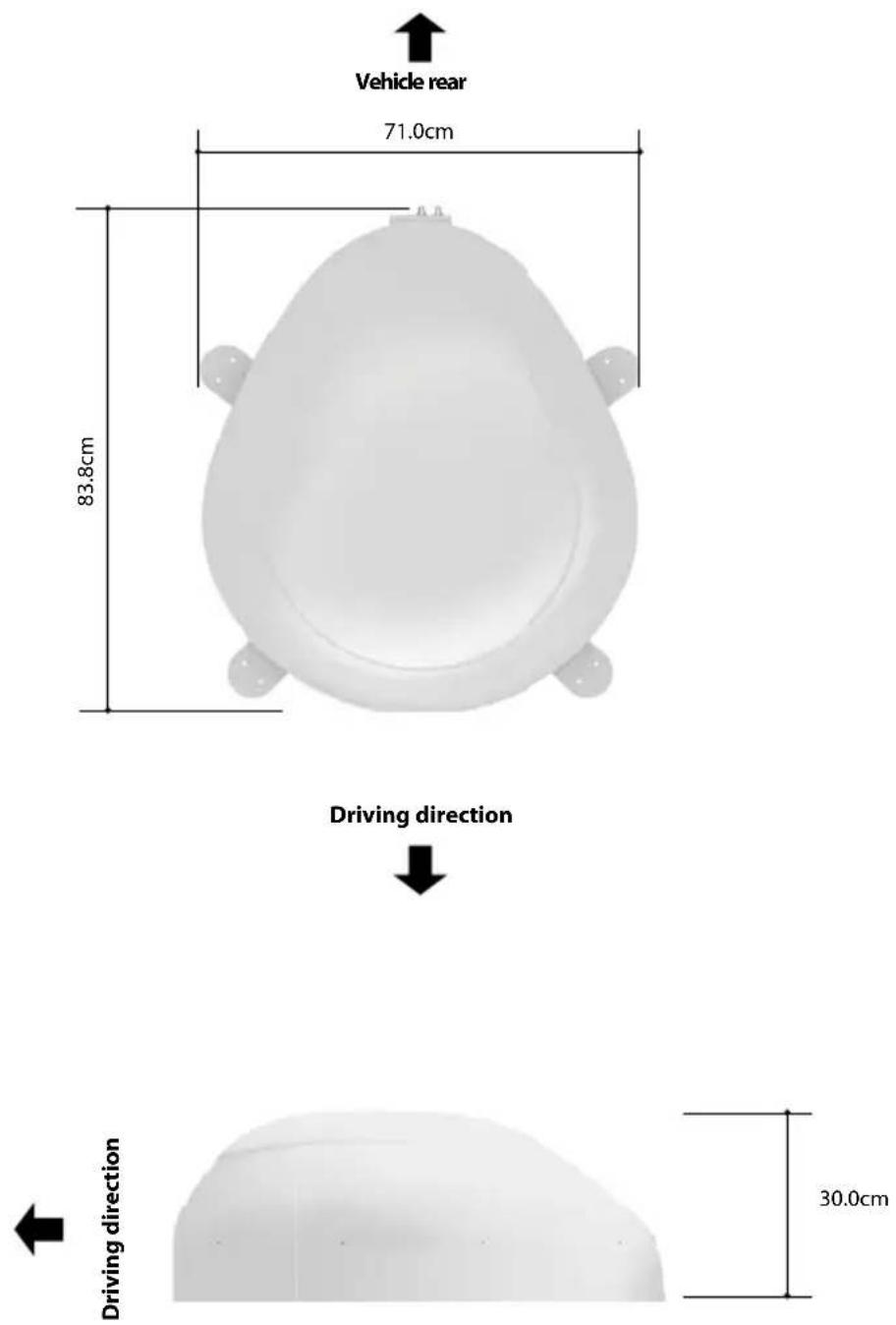
6. Specifications
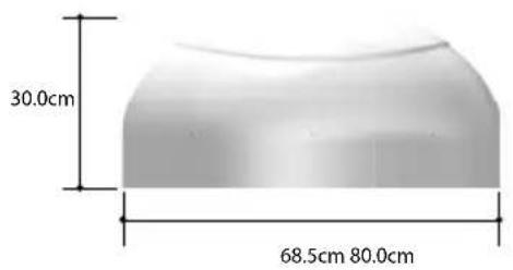
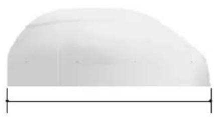
6-1. Dimension
natural_image
White dome-shaped object with a horizontal line at the bottom (no text or symbols)6-2. Specification
| Dimensions | 800 x 685 x 300 mm |
| Weight (Main Unit) | 9.6 kg |
| Antenna Gain | 33.7 dBi @ 12.7GHz |
| Min EIRP | 50 dBW |
| Polarization | Linear (horizontal / Vertical) |
| Output | 1 output / 2 output (Optional) |
| LNB Input Frequency | 10.7 ~ 12.75 GHz |
| LNB Output Frequency | 950 ~ 2,150MHz |
| Angle Range | (EL)15°~75°/(AZ) 390° |
| Satellite Searching Tie | 120 Seconds (Average) |
| Power Requirement | 30W (in searching) |
| Input Voltage | DC 12~24V |
| Operating Temperature | -30°C ~ +60°C |
7. Camping Car Installation
7-1. Required space for the SNIPE DOME
Take care, that there is enough space for the SNIPE DOME, just as for the operation range.
7-2. Equipment for Installation
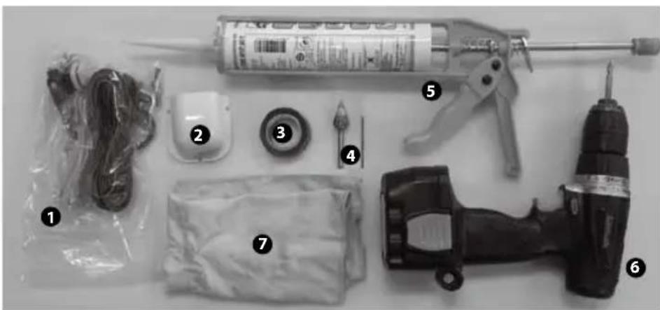
natural_image
Assorted electrical components including a syringe, power tool, and motor (no visible text or labels)1 Installation Kit (Screws M4x20(11)/ M4x16(2), Cable gland, Cable gland rubber, Cigar jack adaptor)
2 Cable holder
3 Friction tape
4 2mm drill bit, 15mm drill bit
5 Silicone
6 Power drill
7 Cleaner
SNIPE DOME Installation on the car roof (same for all 4 mounting plate edges)
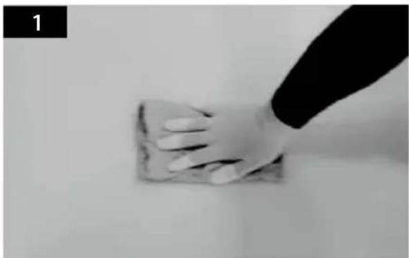
natural_image
Hand cleaning a surface with a cloth (no text or symbols visible)Clean the surface with cleaner.
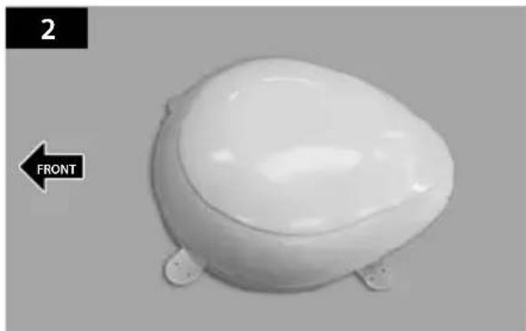
natural_image
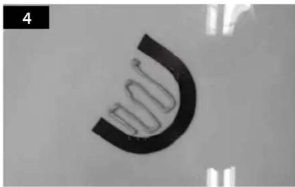
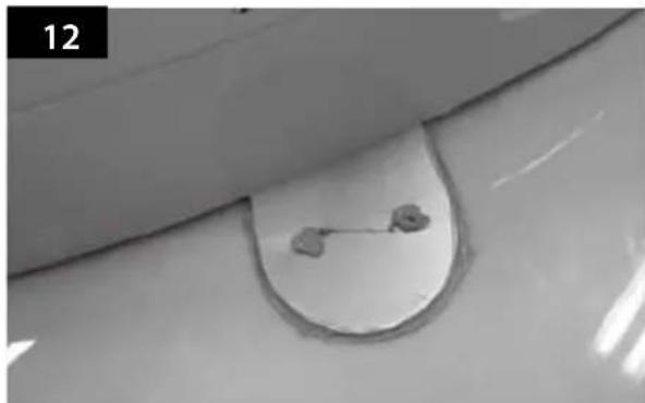
White ceramic toilet with a side panel labeled 'FRONT' and number '2' (no other text or symbols)Locate SNIPE DOME in the center of car roof.

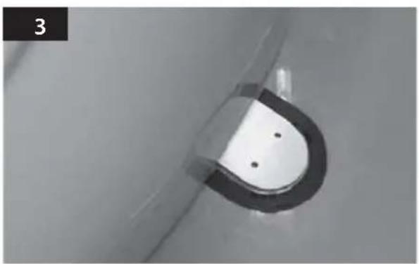
natural_image
Close-up of a metallic U-shaped component with two small holes, no visible text or symbolsAttach friction tape outside of the mounting plate, to be 4mm away from it.
natural_image
Close-up of a black curved object with a wavy line inside, against a plain background (no text or symbols visible)Put aside the mounting plate to apply silicone inside the guided tape line.
natural_image
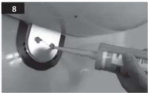
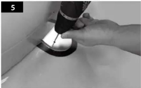
Close-up of a hand using a handheld tool to press or install a circular component on a white surface (no text or symbols visible)Put back the mounting plate on the silicone applied and make 2holes (2mm) with power drill.
natural_image
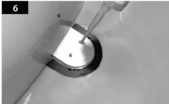
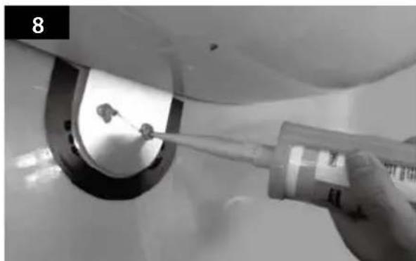
Close-up of a metallic ring component with a small rod inserted, no visible text or symbolsApply silicone on the holes.
natural_image
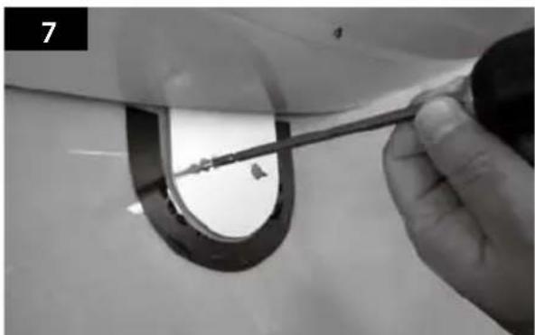
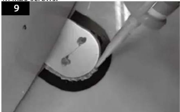
Close-up of a hand holding a tool near a curved mechanical component (no visible text or symbols)Fix mounting plate on the car roof using 2 M4x20 screws.
natural_image
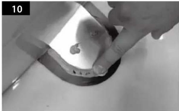
Close-up of a hand using a tool to clean or inspect a circular object, no visible text or symbolsRe-apply silicone to cover tightened screws.
natural_image
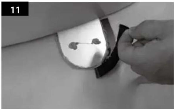
Close-up of a hand using a pipette to apply liquid onto a circular object, no visible text or symbolsApply silicone around the mounting plate.
natural_image
Close-up of hands cleaning a metal pipe with a small object on the surface (no text or symbols visible)Tidy the area silicone applied.
natural_image
Hand placing a small object into a dark rectangular component, possibly a device or sensor, with no visible text or symbols.Remove the friction tape and get dry.
natural_image
Close-up of a curved metallic object with a circular hole and two small protrusions, possibly a valve or fixture (no text or symbols visible)The image you will see. Place main unit on the top of fixed plate.
natural_image
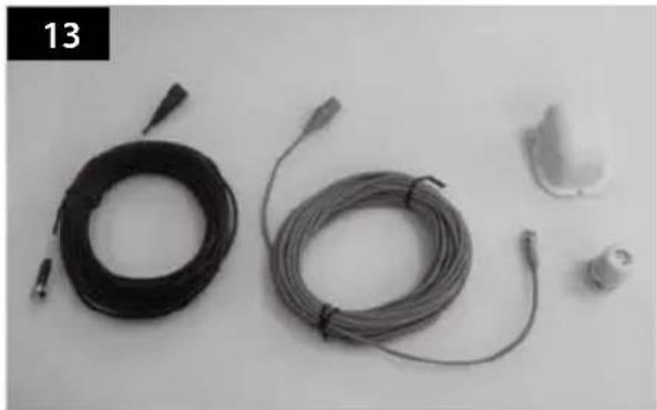
Black and white photo of coiled cable and connector components on a plain surface (no text or symbols visible)Equipment to initiate Cable holder installation.
natural_image
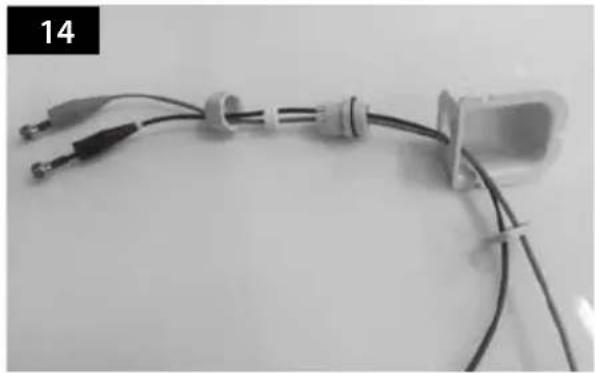
Close-up of a medical or laboratory setup with coiled wires and connectors, no visible text or symbolsPut the cable inside the Cable holder as above picture.

natural_image
Top-down view of a white plastic component with a black base, no visible text or symbolsArrange cable holder in front of (30cm apart from) antenna center by facing open side of cable holder toward projected part of the mounting plate. Then attach friction tape outside of cable holder.
natural_image
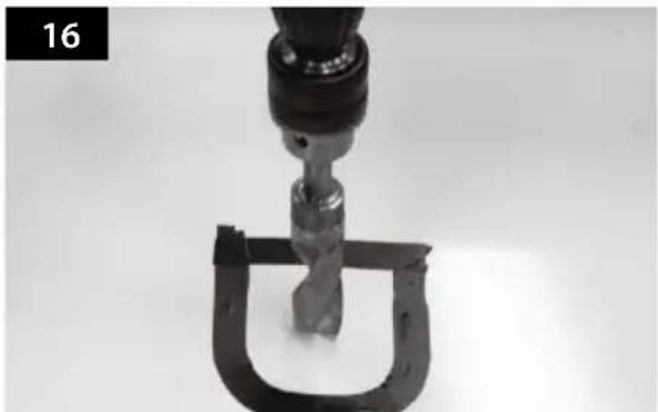
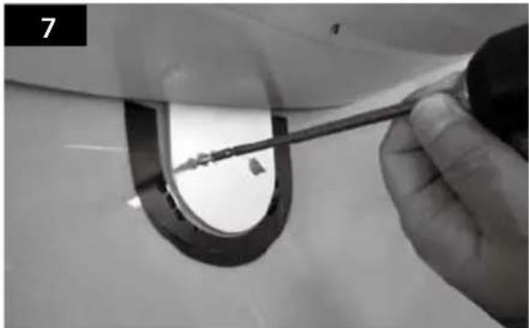
Close-up of a mechanical tool with a U-shaped clamp and metal component, no visible text or symbolsMake 15mm drill hole in the center of the tape marking.
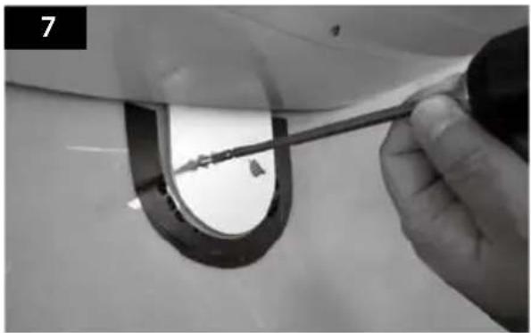
natural_image
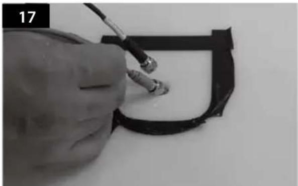
Close-up of a hand using a tool to cut or mark a black curved object, no visible text or symbolsInsert Receiver & controller cable through the hole.
natural_image
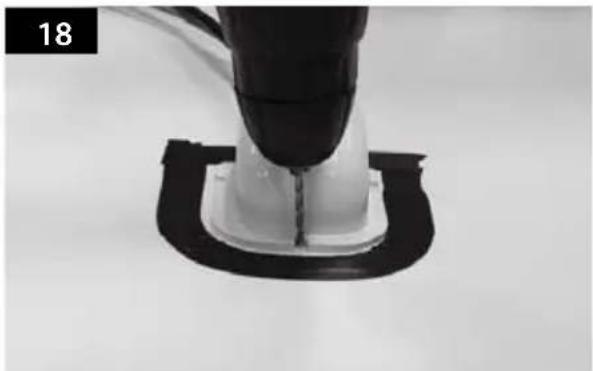
Close-up of a mechanical component with a black tool inserted into a white housing, mounted on a black base (no visible text or symbols)Place cable holder in the tape marked and make 3 of 2mm drill holes.
natural_image
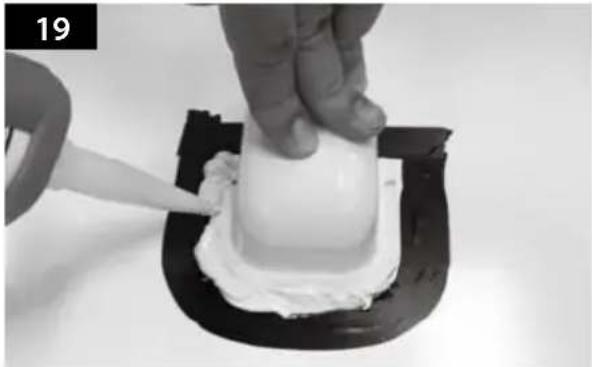
Close-up of a hand smoothing white substance on a black base, no text or symbols visibleApply silicone around the cable holder.
natural_image
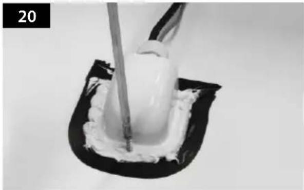
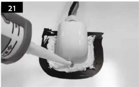
Close-up of a white cream being piped into a black square cushion (no text or symbols visible)Fix cable holder on the car roof with 3 of M4x20 screws.
natural_image
Close-up of a hand pouring white powder onto a small white object on a black surface, no visible text or symbolsApply silicone around and on the top of screws.

natural_image
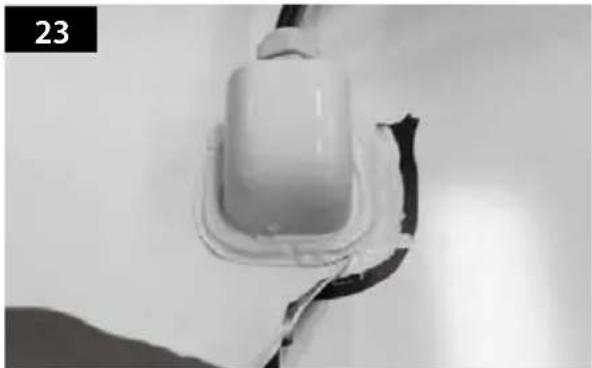
Close-up of a hand pressing a white cream on a small object, possibly a dessert or pastry (no text or symbols visible)Tidy silicon.
natural_image
Close-up of a white plastic electrical plug or socket mounted on a surface, with a black cable wrapped around it (no visible text or symbols)Remove friction tape.
natural_image
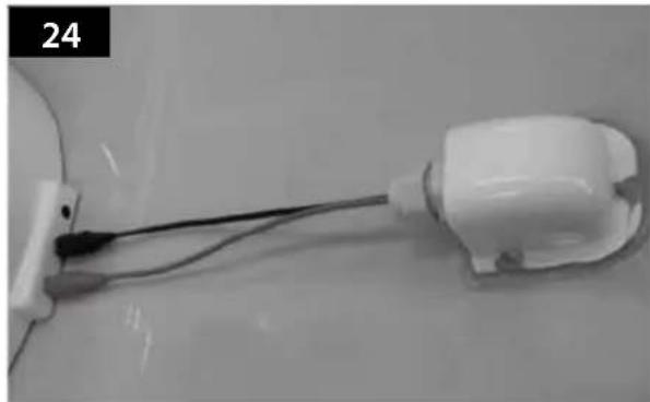
Close-up of a white plastic electrical plug connected to a cable, with no visible text or symbols.Connect black cable to the controller(middle) and grey cable to the receiver(Left).
a. Use controller cable(Black Color) and Cigar jack adaptor to connect to the Controller.
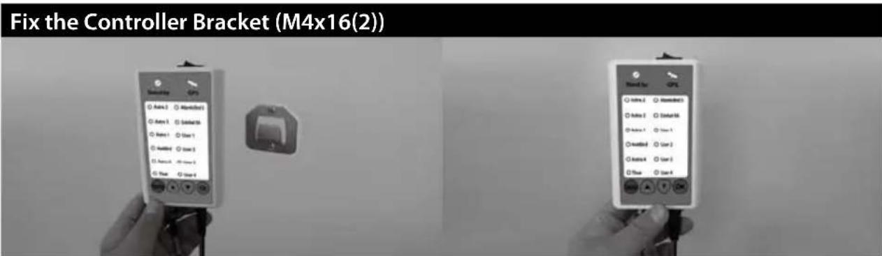
b. Fix the Controller Bracket at where you want.
c. Place the Controller on the Controller Bracket.
Inhalt
natural_image
3D rendered white object resembling a dome-shaped container or ergonomic device (no text or symbols visible)natural_image
White 3D-rendered object resembling a stylized helmet or cushion, with no visible text or symbols.Haupteinheit

natural_image
Coiled black cable or wire with connectors, isolated on white background (no text or symbols)natural_image
Exterior view of a white electronic device with ports and indicator lights (no visible text or symbols)Steuergerät
natural_image
Pure electrical circuit symbol for a battery, no text or labels presentnatural_image
Coiled black cable with connectors, no visible text or symbolsnatural_image
Black cable with two connectors, isolated on white background (no text or symbols)natural_image
White plastic mechanical component with a circular hole, shown in a rounded corner (no text or symbols)Kabelhalter
natural_image
Close-up of a white plastic connector or fitting with a black seam, isolated on white background (no text or symbols)Kabelverschraubung
natural_image
Group of screws arranged in two rows, no text or symbols presentSchraube M4x20(11), M4x16(2)
Bedienungsanleitung

natural_image
White dome-shaped object with a horizontal dimension line (no text or symbols)natural_image
Assorted electrical components including a syringe, power tool, and motor (no visible text or labels)natural_image
Hand holding a white object over a light-colored surface, no text or symbols visiblenatural_image
White ceramic toilet with a side panel labeled 'FRONT' and number '2' (no other text or symbols)natural_image
Close-up of a metallic U-shaped component with two small holes, mounted on a white surface (no text or symbols visible)natural_image
Close-up of a black curved object with a white wavy line, possibly a pipe or tube (no text or symbols visible)natural_image
Close-up of a hand using a tool to clean or store floor, no visible text or symbolsnatural_image
Close-up of a mechanical component with a curved central part and a rod inserted, no visible text or symbolsnatural_image
Close-up of a hand using a tool to trim a curved metal component, no visible text or symbolsnatural_image
Close-up of a hand using a tool to apply material to a circular component, no visible text or symbols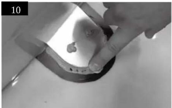
natural_image
Close-up of hands holding a small object over a dark circular surface, possibly a container or mold (no visible text or symbols)natural_image
Close-up of a mechanical component with a tool inserted, showing a circular component and two small holes (no text or symbols visible)natural_image
Close-up of a white surface with a circular opening and two small metallic clips attached (no text or symbols visible)natural_image
Hand holding a small object with two small objects inside a curved metallic frame (no text or symbols visible)natural_image
Black-and-white photo of coiled and connected wires on a plain surface, with no visible text or symbols.natural_image
Close-up of a medical or laboratory setup with coiled wires and connectors, no visible text or symbolsnatural_image
3D rendered object resembling a U-shaped mechanical or electronic component with a white central body and black base (no text or symbols visible)natural_image
Close-up of a mechanical clamp or clamping device with a metallic component inserted into a U-shaped bracket (no visible text or symbols)natural_image
Close-up of a hand using a tool to draw a black rectangular component (no visible text or symbols)natural_image
Close-up of a mechanical component with a black and white base, no visible text or symbolsnatural_image
Close-up of a hand piping white cream onto a small white object on a black base, no text or symbols visiblenatural_image
Close-up of a white substance being piped with a tool, placed on a black surface (no text or symbols visible)natural_image
Close-up of a hand applying white cream to a small white object on a black surface, no text or symbols visiblenatural_image
Close-up of a hand pressing a white foam or cream substance into a black plastic mold (no text or symbols visible)natural_image
Close-up of a white plastic electrical plug or socket with black insulation, no visible text or symbolsnatural_image
Close-up of a white plastic electrical plug with wires, no visible text or symbolsnatural_image
3D rendered white object resembling a stylized helmet or device, with no visible text or symbols.natural_image
3D rendered white dome-shaped object with rounded edges and small protrusions (no text or symbols)Unité principale
natural_image
Black cable with two connectors, isolated on white background (no text or symbols)natural_image
Exterior view of a rectangular electronic device with a small port and indicator lights (no visible text or symbols)Contrôleur

natural_image
Pure electrical circuit symbol for a plug (no text or labels)natural_image
Coiled cable or wire with connectors, no visible text or symbolsnatural_image
Black cable with two connectors, isolated on white background (no text or symbols)Cigar lighter jack câble
natural_image
White plastic mechanical component with a circular hole, shown in a rounded corner (no text or symbols)Support de câble
natural_image
Close-up of a white plastic connector or fitting with a black seam, isolated on white background (no text or symbols)Presse-étoupe

natural_image
Illustration of multiple screws arranged in two rows (no text or symbols)Vis M4 × 20 (11), M4 × 16 (2)


natural_image
White dome-shaped object with a horizontal line at the bottom (no text or symbols)natural_image
Assorted electrical tools including a syringe, power tool, and drill bit (no visible text or labels)natural_image
Hand wiping a rectangular object on a plain surface (no text or symbols visible)natural_image
White ceramic toilet with a side panel, labeled 'FRONT' and number '2' (no other text or symbols)natural_image
Close-up of a metallic mechanical component with a curved end and two small holes, mounted on a flat surface (no text or symbols visible)natural_image
Close-up of a curved, dark, U-shaped object with a white outline, possibly a mechanical or electronic component (no visible text or symbols)natural_image
Close-up of hands using a tool to clean or store floor, no visible text or symbolsnatural_image
Close-up of a medical procedure showing a catheter inserted into a circular device (no visible text or symbols)Appliquez de la silicone.
natural_image
Close-up of a hand holding a tool near a curved mechanical component (no visible text or symbols)natural_image
Close-up of a hand using a pipette to clean or store items around a circular opening (no visible text or symbols)natural_image
Close-up of a pipette dispensing liquid into a circular device with two small components (no visible text or symbols)natural_image
Close-up of hands holding a metallic object with a small, irregularly shaped feature on the surface (no text or symbols visible)natural_image
Close-up of a hand holding a small object with two small objects inside a curved container, no visible text or symbolsnatural_image
Close-up of a white surface with a circular opening and two small circular features, no visible text or symbols.natural_image
Black-and-white photo of coiled wires and a small electronic component on a plain surface (no text or symbols visible)natural_image
Close-up of a medical or laboratory setup with coiled wires and connectors, no visible text or symbolsnatural_image
Top-down view of a white plastic component with a black curved base, labeled '15' in the corner (no other text or symbols)natural_image
Close-up of a mechanical tool interacting with a U-shaped bracket (no visible text or symbols)natural_image
Close-up of a hand using a tool to mark a white object on a black rectangular surface (no text or symbols visible)natural_image
Close-up of a mechanical component with a black and white base, no visible text or symbolsnatural_image
Close-up of hands applying a white substance to a small white object on a black stand (no text or symbols visible)natural_image
Close-up of a white substance being piped with a tool, placed on a black surface (no text or symbols visible)natural_image
Close-up of a hand pouring white cream onto a black surface, no visible text or symbolsnatural_image
Close-up of a hand pressing a white cylindrical object into a black container (no text or symbols visible)natural_image
Close-up of a white electrical plug or socket with a black cable, no visible text or symbolsnatural_image
Close-up of a white plastic electrical plug with wires, no visible text or symbolsnatural_image
3D rendered white object resembling a dome-shaped container or ergonomic device (no text or symbols visible)1-2. Correct gebruik en bediening
natural_image
White 3D-rendered dome-shaped object with rounded edges and small protrusions (no text or symbols)Hoofdunit
natural_image
Black cable with two connectors, isolated on white background (no text or symbols)Bedieningkabel (12m - zwart)
natural_image
Exterior view of a white electronic device with ports and indicator lights (no visible text or symbols)Bediening

natural_image
Pure electrical circuit symbol for a switch or relay (no text or labels)natural_image
Coiled cable or wire with connectors, no visible text or symbolsnatural_image
Black cable with two connectors, isolated on white background (no text or symbols)natural_image
White plastic mechanical component with a circular hole, shown in a rounded corner (no text or symbols)Kabelhouder
natural_image
Close-up of a white plastic connector with a black seam, isolated on white background (no text or symbols)Kabelwartel
natural_image
Illustration of multiple screws arranged in two rows (no text or symbols)Bout M4 × 20 (11), M4 × 16 (2)
Gebruikshandleiding
Download het SNIPE DOME update programma.01.


ontroleer [Update has been completed].07.

LET OP
natural_image
White dome-shaped object with a horizontal line at the bottom (no text or symbols)6-2. Specification
natural_image
Assorted electrical components including a syringe, power tool, and motor (no visible text or labels)natural_image
Hand pressing down on a surface with a cloth (no text or symbols visible)natural_image
3D rendered white toilet or sink with a labeled front view indicator (no text or symbols on the object itself)natural_image
Close-up of a metallic curved component with two small holes, possibly a sensor or connector (no text or symbols visible)natural_image
Close-up of a hand using a tool to clean or store floor, no visible text or symbolsnatural_image
Close-up of a mechanical component with a central circular feature and a tool inserted, no visible text or symbolsSpuit siliconenkit in de gaten.
natural_image
Close-up of a hand holding a tool interacting with a circular mechanical component (no visible text or symbols)natural_image
Close-up of a hand using a spray bottle to clean or store floor tiles near a circular opening (no visible text or symbols)natural_image
Close-up of a pipette dispensing liquid into a circular mechanical component (no visible text or symbols)natural_image
Close-up of hands holding a small transparent object with a small irregular shape inside, against a plain background (no text or symbols visible)natural_image
Hand holding a black plastic clip attached to a circular object, with two small objects inside (no text or symbols visible)natural_image
Close-up of a circular mechanical component with two small protrusions, mounted on a curved surface (no text or symbols visible)natural_image
Black-and-white photo of various electronic components including coiled wires, connectors, and a small device (no visible text or symbols)natural_image
Close-up of a medical or laboratory setup with coiled wires and connectors, no visible text or symbolsnatural_image
3D rendered object resembling a U-shaped mechanical component with a white central body and black base (no text or symbols visible)natural_image
Close-up of a mechanical clamp or tool with a metallic component inserted into a U-shaped bracket (no visible text or symbols)natural_image
Close-up of a hand holding a black cable with a metallic screw, partially enclosed in a black frame (no text or symbols visible)natural_image
Close-up of a robotic arm gripping a white plastic component with black base (no text or symbols visible)natural_image
Close-up of a hand piping white cream onto a small white object on a black base (no text or symbols visible)natural_image
Close-up of a white substance being piped with a brush, placed on a black surface (no text or symbols visible)natural_image
Close-up of a hand pouring white cream onto a black plastic container (no text or symbols visible)natural_image
Close-up of a hand pressing a white cylindrical object into a black container (no text or symbols visible)Strijk de siliconenkit glad.

natural_image
Close-up of a white plastic container with a black strap, no visible text or symbolsnatural_image
Close-up of a white plastic electrical plug connected to a black cable, with no visible text or symbols.natural_image
3D rendered white object resembling a dome-shaped container or helmet (no text or symbols visible)natural_image
3D rendered white object resembling a stylized helmet or pod, with no visible text or symbols.Huvudenhet
natural_image
Coiled black cable or wire with connectors, isolated on white background (no text or symbols)natural_image
Exterior view of a white electronic device with ports and display screen (no visible text or symbols)Kontrollenhet
natural_image
Metallic electrical connector or switch component (no text or symbols visible)Hallare kontrollenhet
natural_image
Coiled black cable or wire with connectors, no visible text or symbolsnatural_image
Black cable with two connectors, isolated on white background (no text or symbols)kabel för ciggarettuttag
natural_image
White plastic mechanical component with a circular hole, shown in a rounded corner (no text or symbols)Kabelhus
natural_image
Close-up of a white plastic connector with a black seam, isolated on white background (no text or symbols)Kabelgenomforing
natural_image
Group of screws arranged in two rows, no text or symbols presentVis M4x20(11), M4x16(2)

02-c. Gå till [avancerad...]
natural_image
White dome-shaped object with a horizontal dimension line (no text or symbols)6-2. Specifikationer
natural_image
Assorted electrical components including a syringe, power tool, and drill bit (no visible text or labels)1 Installation Kit (M4x20 (11), M8 flänsmutter (4), Kabelgenomföring, Cigarettändaren kabel)
2 Kabelhus
3 Skyddstejp
4 2 mm borr, 15 mm borr
5 Tätningsmedel
6 Borrmaskin
7 Rengöringsmedel
natural_image
Hand wiping a rectangular object on a plain surface (no text or symbols visible)natural_image
White ceramic toilet with a side panel and 'FRONT' label, shown against a plain gray background (no text or symbols on the toilet itself)Lokalisera SNIPE DOME i mitten av biltaket.
natural_image
Close-up of a metallic U-shaped component with two small holes, possibly a sensor or connector (no text or symbols visible)natural_image
Close-up of hands using a tool to clean or repair a circular component on a bathtub (no text or symbols visible)natural_image
Close-up of a mechanical component with a curved ring and a tool inserted, no visible text or symbolsnatural_image
Close-up of a hand holding a tool interacting with a curved mechanical component (no visible text or symbols)Fix monteringsplattan på biltaket med 2 M4x20 skruvar.