Snipe Mobil Camp - Receiver Selfsat - Free user manual and instructions
Find the device manual for free Snipe Mobil Camp Selfsat in PDF.

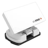
| Product type | Automatic portable satellite antenna with integrated receiver |
| Brand | Selfsat |
| Model | Snipe Mobil Camp |
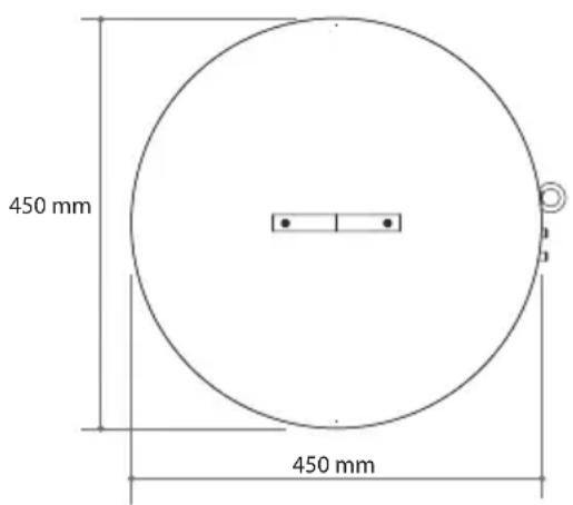
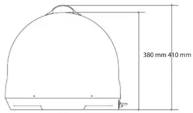
| Dimensions (W x H) | 450 x 410 mm |
| Weight | 4.7 kg |
| Power supply | DC 12~24 V |
| Power consumption | 30 W (while moving) |
| Input frequency | 10.7 ~ 12.75 GHz |
| Polarization | Horizontal / Vertical |
| Antenna gain | 31.0 dBi |
| Elevation angle | 5° ~ 90° |
| Azimuth angle | 360° |
| Skew adjustment | Manual (automatic optional) |
| Satellite switching system | DiSEqC 1.1 |
| Average search time | 180 seconds |
| LNB output | 1 or 2 |
| LNB output frequency | 950 ~ 2,150 MHz |
| LO frequency | 9.75 / 10.6 GHz |
| Anti-theft protection | Dual surveillance: physical lock + audible alarm |
| Recommended installation | Clear view to the south, avoid obstacles (trees, buildings) |
| Maintenance | Do not paint or drill the cover; remove snow; do not expose to impacts |
Frequently Asked Questions - Snipe Mobil Camp Selfsat
User questions about Snipe Mobil Camp Selfsat
0 question about this device. Answer the ones you know or ask your own.
Ask a new question about this device
Download the instructions for your Receiver in PDF format for free! Find your manual Snipe Mobil Camp - Selfsat and take your electronic device back in hand. On this page are published all the documents necessary for the use of your device. Snipe Mobil Camp by Selfsat.
USER MANUAL Snipe Mobil Camp Selfsat
natural_image
Simple line drawing of a dome-shaped object with a bus and pine trees nearby (no text or symbols)ENGLISH: User's manual
3-1. Coverage 6
3-2. Skew adjustment 7
4. Operating Instruction
4-1. Connection diagram 8
4-2. Advanced Theft Protection 9
5. Functional description
5-1. Power turn on & off 10
5-2. Searching the satellite 10
5-3. DiSEqC setting 11
5-4. Factory reset 11
5-5. Software upgrade 12
6. Troubleshooting
7. Specifications
7-1. Dimension 14
7-2. Specifications 14
1. General Information
1- 1. Introduction
These instructions describe the functions and operation of the portable satellite antenna system.
Correct and safe operation of the system can only be ensured by following these instructions.
Your antenna is an intelligent satellite TV reception antenna system which can align itself towards a preset satellite automatically as long as the system is located within the footprint of the selected satellite.
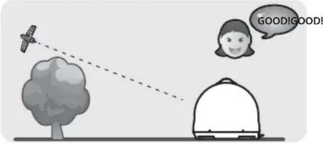
For general operation, please ensure that the system always has a clear view to the sky. If the satellite's signal beam is interrupted by obstacles such as mountains, buildings or trees, the product will not function and no TV signal will be received.
1-2. Where to install?
In order to receive a signal from the Satellite, the product has to be installed in an open space the direction of the satellite towards the equator.
Make sure that there are no obstacles in front of the product which can decrease the signal reception quality, such as buildings or trees.
Bad Quality Singnal Reception
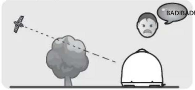
Good Quality Singnal Reception
Signal loss / Rain Fade
- The satellite signal may be lost temporarily due to unusually heavy rainfall. An optimally aligned antenna, along with the shortest possible cable run, minimizes the chances of "rain fade".
- Heavy snow accumulation on the antenna may reduce the satellite signal strength; snow should be swept away as soon as possible.
- Tree foliage growth into antenna's line-of-sight to the satellite may result in gradual loss of picture.
1-3. Safety notes
Before using this product, please read this manual carefully and follow all the installation, mounting & orientation instructions correctly. All the instructions should be followed in order to avoid any technical problems.
Please also note the following instructions from the manufacturer :
- Do not open the cover, any attempt to repair by a non-qualified person can be dangerous and void the warranty.
- Do not make any holes on the plastic antenna cover to prevent from water penetration.
- When handling the antenna, please do it carefully as any impact might cause damage to the electronics.
- Any electric or magnetic field close to the antenna may cause a bad reception or even cut off the signal completely.
- Do not paint or add any substance on the antenna cover, this will block the reception of the signal from the satellite.
- The use non-isolated jacks will result in a loss of the signal level.
- Be careful when connecting or disconnecting the antenna cable. Using it in an abnormal condition or pulling it by force may damage the product or the cable.
- Before moving the product, turn off the power and disconnect all connected cables. This may damage the product, fall over the connection line and get injured.
- Install the product in a suitable location (flat surface or on a level surface where the product can be placed reliably) depending on installation environment. If not, this may damage the product or cause an accident.
- Any obstacle (buildings, trees, etc....) will block the reception of the signal from the satellite to the antenna.
- For more precise details on the above points or for any information, please ask your retailer or customer service.
2. Contents
2-1. Components bundle
natural_image
Line drawing of a dome-shaped object with a handle and base (no text or symbols)Main unit
natural_image
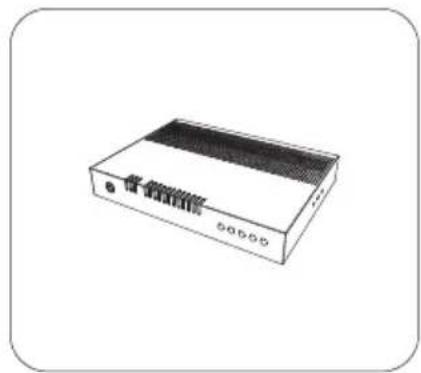
Illustration of a white electronic device with a black top panel and control buttons (no text or symbols visible)Controller Controller bracket,
natural_image
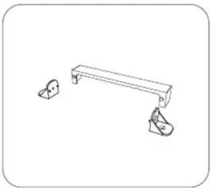
Simple line drawing of a bench with two small accessories (no text or symbols)Rear cable cover

natural_image
Simple line drawing of a rectangular object with a flat top and rounded corners (no text or symbols)RF remote control

natural_image
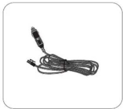
Coiled black cable with a connector, isolated on white background (no text or symbols)Power input cable (Cigarette lighter adaptor)
natural_image
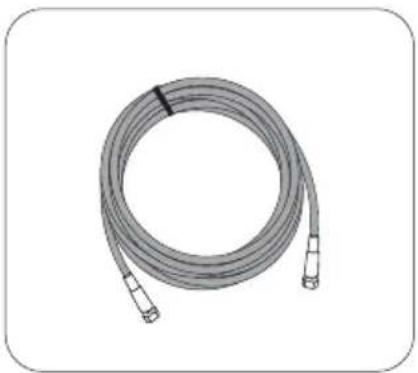
Coiled cable with connectors, no visible text or symbolsSignal cable - 10m (x2 for twin output)
natural_image
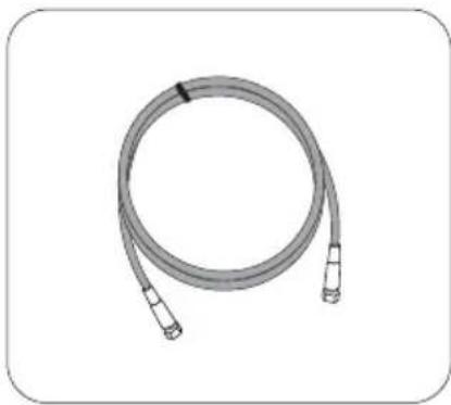
Coiled cable with connectors, no text or symbols visibleSTB cable - 1m

natural_image
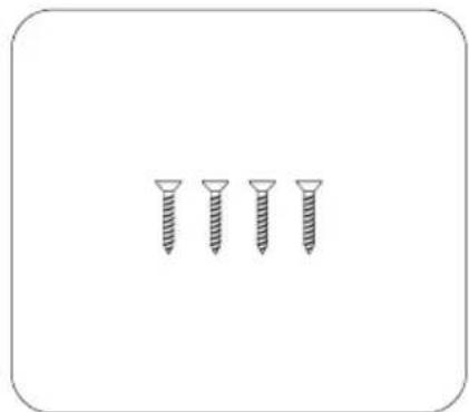
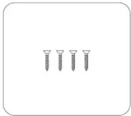
Four screws arranged in a row, no text or symbols presentScrew (F/H 4x20 (4EA)) User manual
natural_image
Simple line drawing of a blank rectangular sheet inside a rounded rectangle (no text or symbols)※ Actual components may differ from the above images.
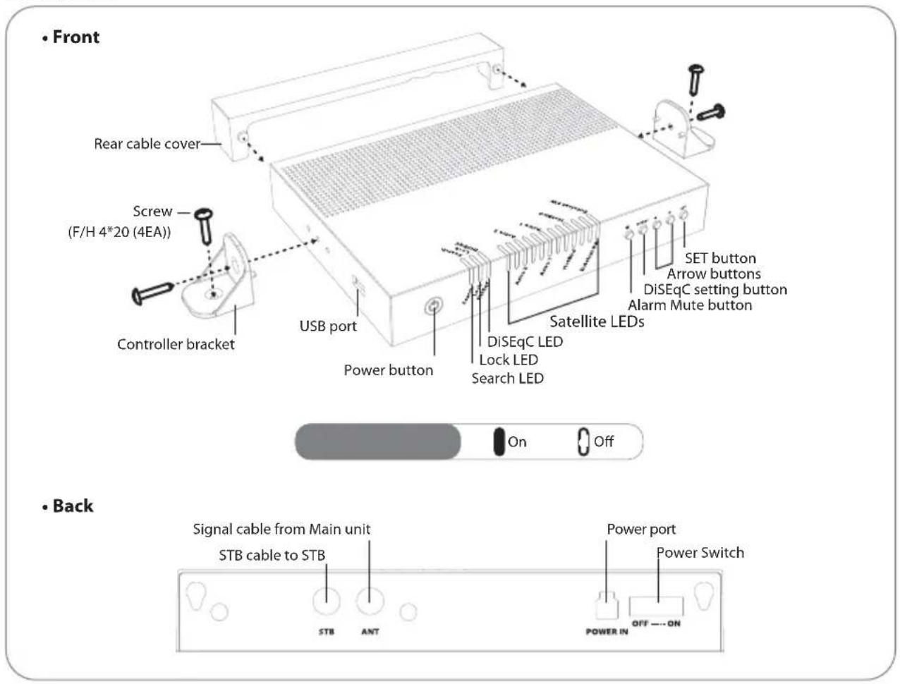
2-2. Name of parts
Main unit RF remote control
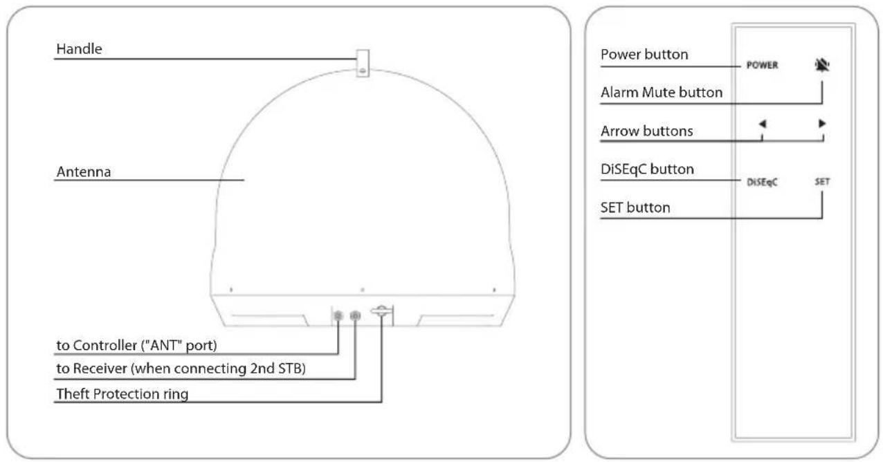
Controller
3. Coverage
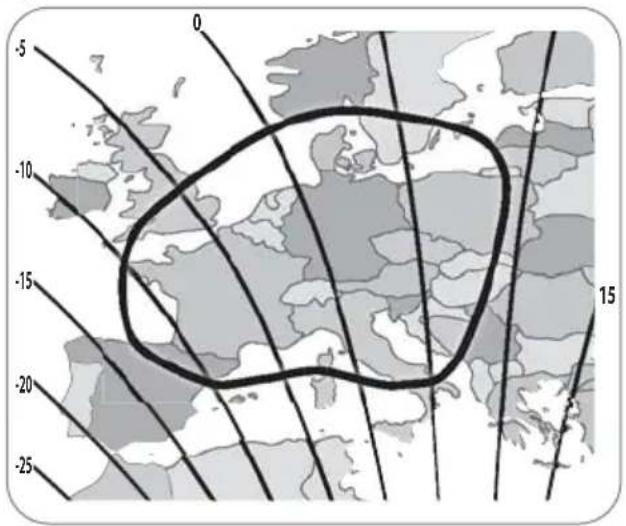
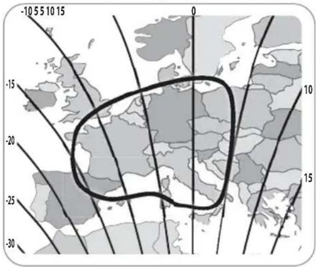
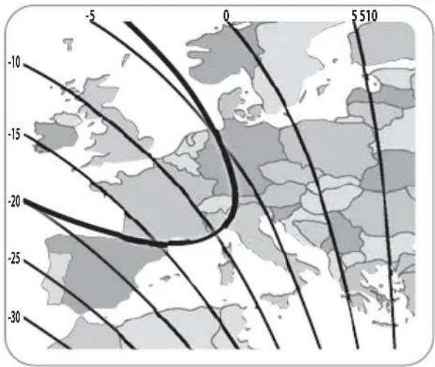
3-1. Coverage
Astra2 @ 28.2°E Astra1 @ 19.2°E

HotBird @ 13.0°E Eutelsat 5W @ 5.0°W
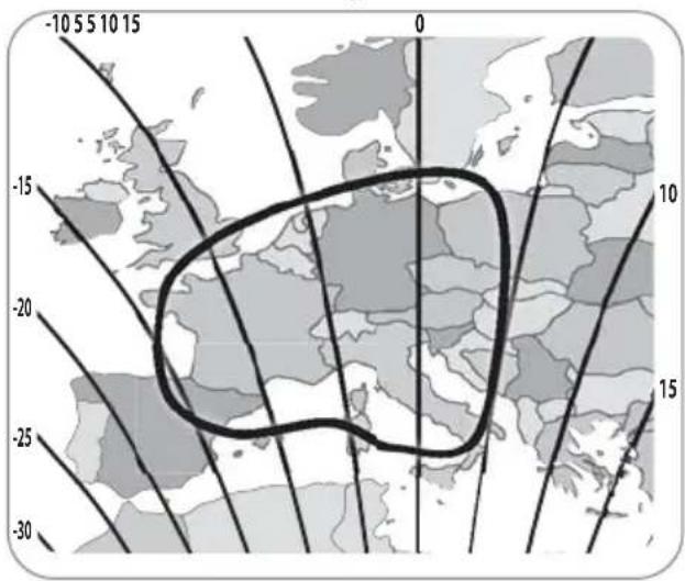
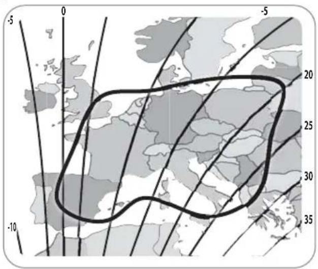

NOTE
※ There might be restrictions on receiving broadcasting depending on the area and target satellite.
※ There is a difference in the best skew angle for a target satellite according to the region.
※ Default skew angle is -5 degrees.
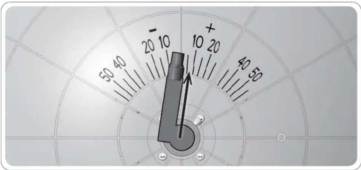
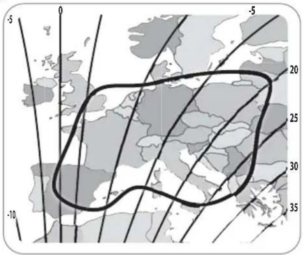
3-2. Skew adjustment
By adjusting the skew angle to match the target satellite, more channels can be received
※ Skew adjustment in this product includes the process of removing the case.
※ As there would be limitation on the warranty for products with damaged seal label, please contact your dealer before proceeding.
radar
| Angle (°) | Value | | --------- | ----- | | 0 | 10 | | 40 | 10 | | 80 | 10 | | 120 | 10 | | 160 | 10 | | 200 | 10 | | 240 | 10 | | 280 | 10 | | 320 | 10 | | 360 | 10 | | 400 | 10 | | 440 | 10 | | 480 | 10 | | 520 | 10 | | 560 | 10 | | 600 | 10 | | 640 | 10 | | 680 | 10 | | 720 | 10 | | 760 | 10 | | 800 | 10 | | 840 | 10 | | 880 | 10 | | 920 | 10 | | 960 | 10 | | 1000 | 10 |Example : In case of changing to Tours, France for receiving Eutelsat 5W from the default setting
Step 1. Check the skew angle of the target satellite (Skew angle in Tours, France is about +7 degree. Refer to page 6)
Step 2. Disassemble the cover and check the LNB angle (The default setting is -5 degree)
Step 3. Slightly loosen the screws fixing LNB and adjust the LNB to scale, then tighten the screws again
Step 4. Operate the product and confirm that Eutelsat 5W is received. (It will be easy to check the satellite's signal quality on STB with turning the LNB little by little.)
Step 5. Re-assemble the cover
4. Operating Instruction
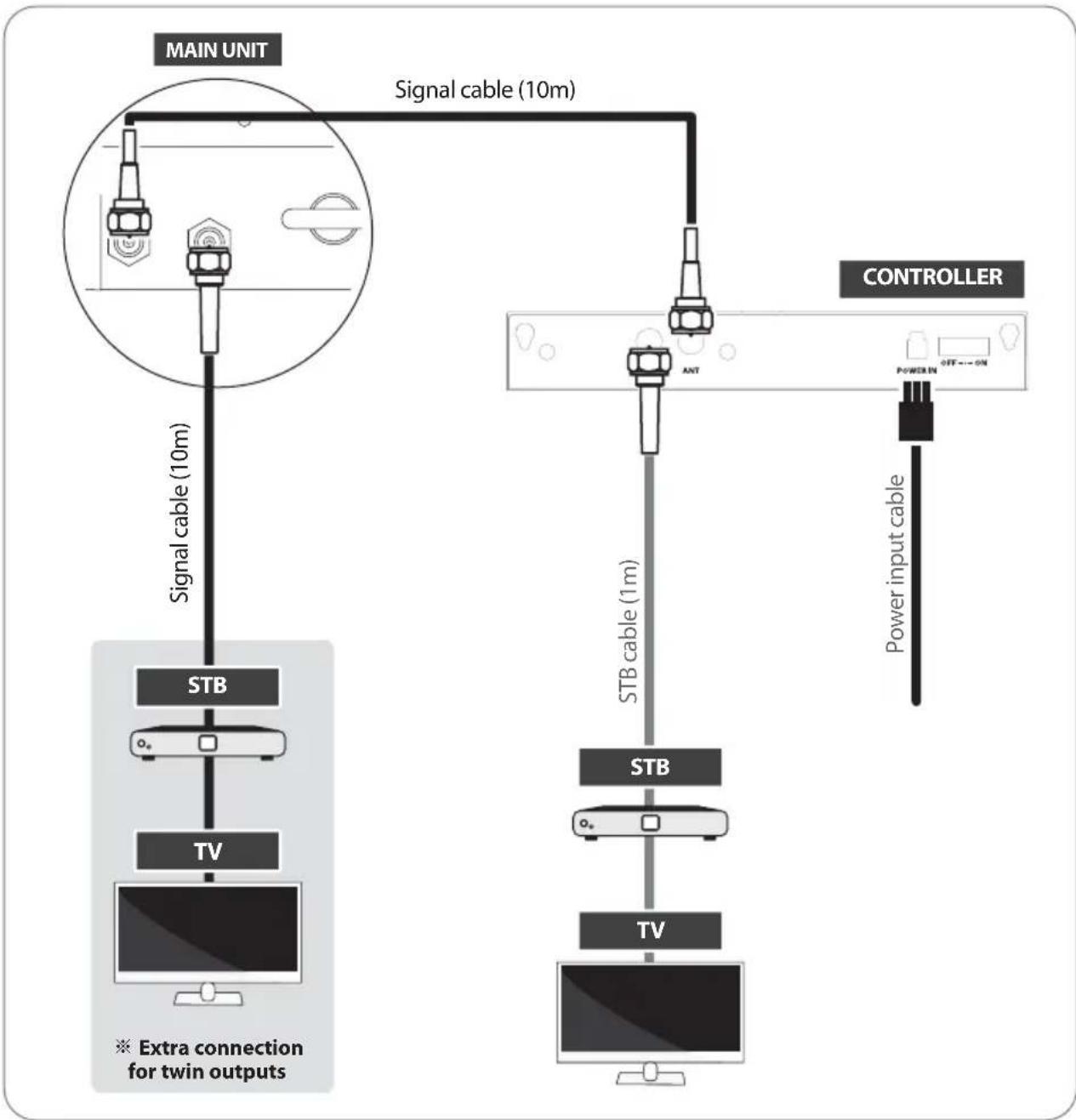
4-1. Connection diagram
flowchart
graph TD
    A["MAIN UNIT"] -->|Signal cable (10m)| B["STB"]
    A -->|Signal cable (10m)| C["TV"]
    A -->|Signal cable (10m)| D["Power input cable"]
    B --> E["STB"]
    C --> F["TV"]
    D --> G["Controller"]
    style A fill:#f9f,stroke:#333
    style B fill:#ccf,stroke:#333
    style C fill:#ccf,stroke:#333
    style D fill:#ccf,stroke:#333
    style E fill:#dfd,stroke:#333
    style F fill:#dfd,stroke:#333
    style G fill:#dfd,stroke:#333
- There is one cable connection from the main unit to the controller
- Use signal cable to connect the controller and the cable running out from the main unit
• Use STB cable (the shortest cable) to connect the controller and STB - For automatic satellite search, first [Controller] output should be connected to the controller. Second [Receiver] output should be connected to second STB directly
- Please use the correct cable for the job
- Please ensure the provided cables are used and not modified in anyway
4-2. Advanced Theft Protection
Dual theft protection by locking and alarm system
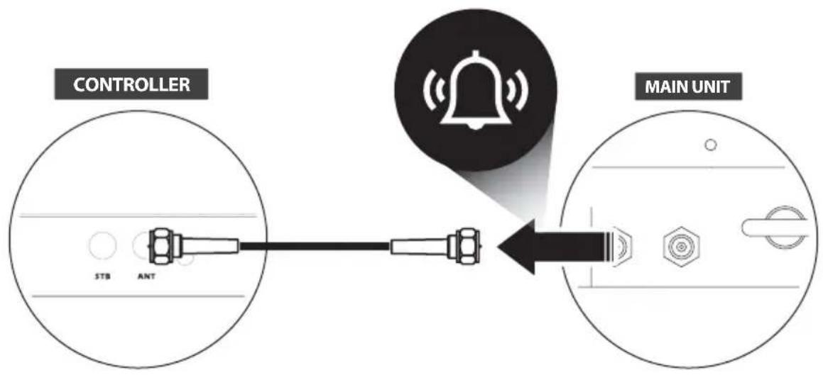
• Visible antenna locking system (Chain linkable ring)
- Invisible antenna alarm system (Buzzer operates when disconnecting the cable between antenna and controller)
How to turn off the buzzer
Step 1
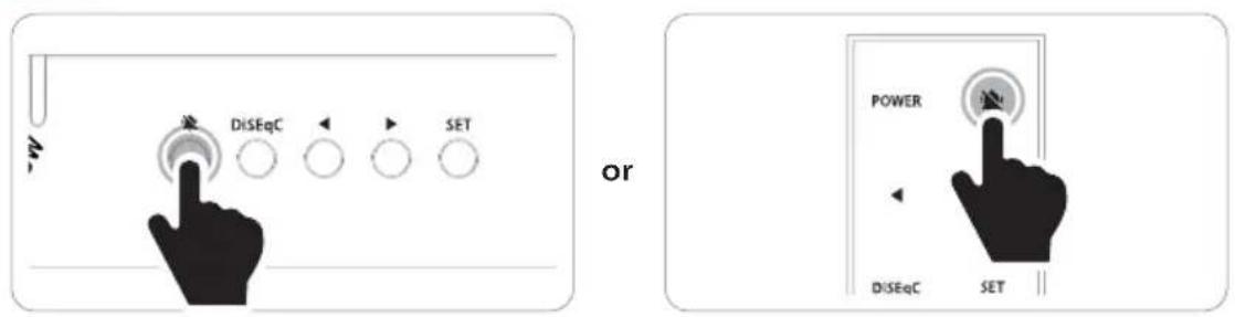
Press Mute button on the controller Press Mute button on the remote control
Step 2
To re-start alarm function, turn off / on the backside power switch of the controller
5. Functional description
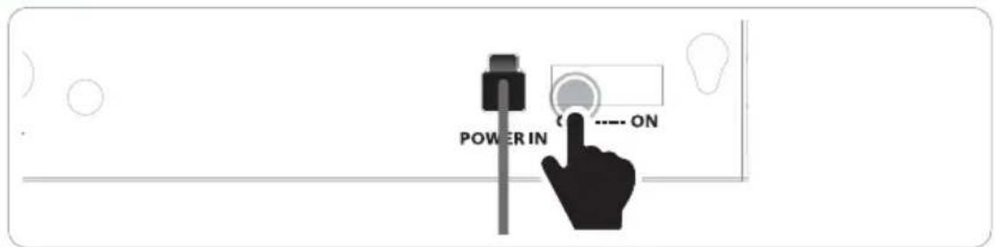
5-1. Power turn on & off
a. Turn on the backside power switch of the controller
b. Press the power button to turn on / off
c. When the backside power switch is on, operation can be adjusted by RF remote control
5-2. Searching the satellite
All satellite LEDs blink and then system is displayed like below image
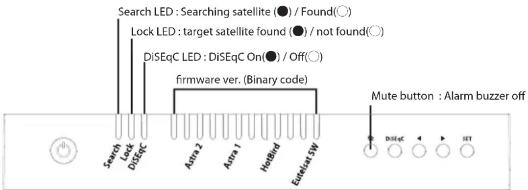
a. When the controller is turned on, some LEDs light indicate firmware version (It is made by binary code and for future service purpose)
b. Once the product is ready to use, three LEDs of satellite are lit ON at default satellite
c. Go to the target satellite using arrow buttons and press SET button to confirm
d. During satellite search, Search LED is on for antenna status
e. Lock LED becomes solid when the target satellite is found
f. DiSEqC LED Default is OFF (Default setting for DiSEqC is OFF)
5-3. DiSEqC setting
Refer product's pre-satellites for DiSEqC 1.1 when user setup at STB
a. Default setting for DiSEqC is OFF, DiSEqC LED is off
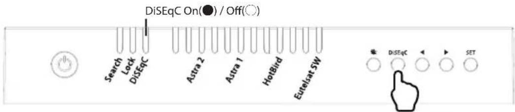
b. To switch the function ON/OFF, press DiSEqC button for DiSEqC can be executed (See also DiSEqC LED status changes between ON and OFF)
c. For DiSEqC operating, user needs to assign DiSEqC satellites list at STB is in same order as above product's pre-set list
5-4. Factory reset
a. Check the backside power switch is off
b. Press and hold ◀ button, and turn on the backside power switch
c. Check all satellite LEDs are on
d. Release ◀ button, then all satellite LED's are off
e. Factory reset is completed
Warning
If upgrade or factory reset is applied, all stored data will be removed.
5-5. Software upgrade
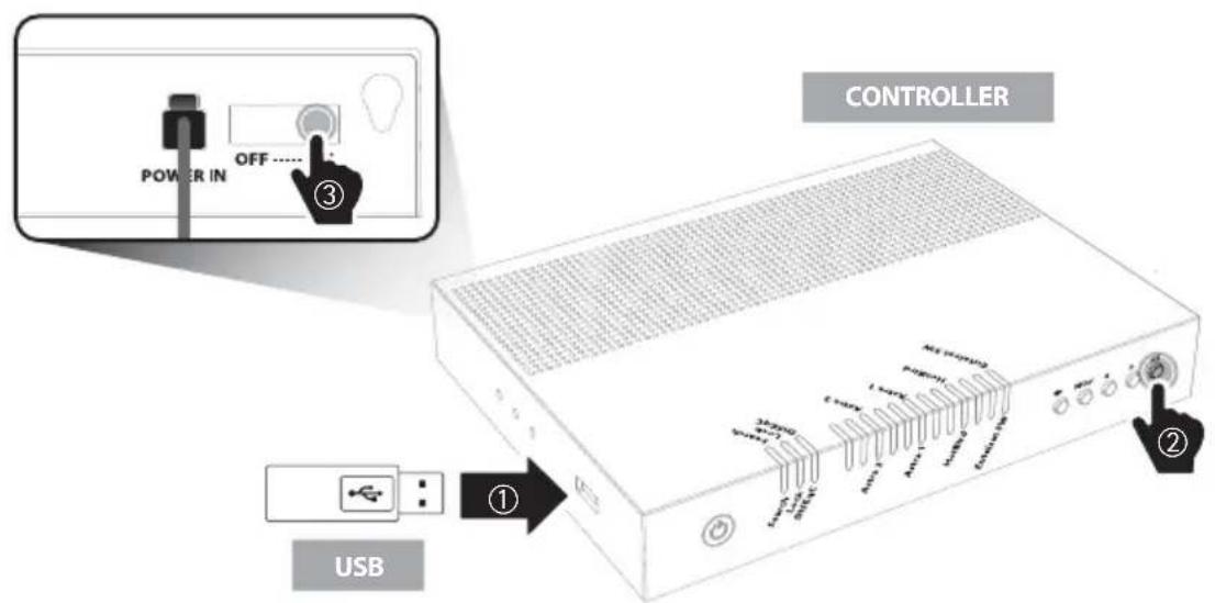
- Transfer software program to a USB root folder (not belonging to any other folder) in an empty USB
i. Please go to website www.selfsat.com to download upgrade program (software)
ii. In case a controller does not recognize the USB drive, take the USB out and plug into a PC. Right click USB folder, go to "Properties" and check if the "File system" is FAT32. If not, right click USB folder again, go to "Format" and re-setup a file system to FAT32
- Ensure that the product is turned off and plug the USB into USB port of controller
- Press and hold SET button then turn on the backside power switch
- During upgrade process, satellite LEDs are lit in sequence
- Once upgrade is completed, controller starts to reboot

NOTE
※ Firmware file should be stored in the USB root directory.
※ Use FAT32 format USB only.
※ Only USB 2.0 standard has to be used for upgrade.
6. Troubleshooting
There are a number of common issues that can affect the signal reception quality or the operation of the product. The following sections address these issues and potential solutions
A. No function when power on the controller
i. Check again all the cable connections have been made correctly.
- Connection between the power and controller.
- Connection between the controller and antenna.
- Make sure that the left port of the antenna should be connected to the controller.
ii. Check if the power input cable has been damaged.
iii. Check the backside power switch of the controller.
iv. Alarm sound
- Turn off the backside power switch and check the antenna connection, then turn on the power.
B. Fail to search the selected satellite
i. Satellite signals can be blocked or degraded by buildings, trees.
Make sure there are no obstructions in a southward direction.
ii. Select another satellite as example Astra1, if this locks then select your desired satellite.
iii. Turn the product off and then back on again and select desired satellite.
C. Other issues
i. If the system has been improperly wired, it will not operate properly. Contact local dealer/shop for assistance of cable damage.
7. Specifications
7-1. Dimension
7-2. Specifications
| Input Frequency | 10.7 ~ 12.75 GHz |
| Polarization | Vertical & Horizontal |
| Antenna Gain | 31.0 dBi |
| Size (D x H) / Weight | 450 X 410 mm / 4.7 kg |
| Min EIRP | 51 dBW |
| Angle Range (EL / AZ) | 5° ~ 90° / 360° |
| Skew | Manual / Auto Skew (optional) |
| Satellite Switching System | DiSEqC 1.1 |
| Satellite Searching Time | 180 seconds (average) |
| LNB Output | 1 / 2 |
| Output Frequency | 950 ~ 2,150 MHz |
| LNB L.O. Frequency | 9.75 / 10.6 GHz |
| Input Voltage | DC 12 ~ 24 V |
| Power Consumption | 30 W (in searching) |
Inhaltsverzeichnis
natural_image
Line drawing of a dome-shaped object with a handle and base, resembling a helmet or cap (no text or symbols)Haupteinheit

natural_image
Illustration of a white electronic device with a black top panel and control buttons (no text or symbols visible)natural_image
Simple line drawing of a bench with two small accessories (no text or symbols)natural_image
Simple line drawing of a rectangular object with a flat top and rounded corners (no text or symbols)RF Fernbedienung

natural_image
Coiled black cable with a connector, isolated on white background (no text or symbols)natural_image
Coiled cable with connectors, no visible text or symbolsnatural_image
Coiled cable with connectors, no text or symbols visibleSTB-Kabel - 1m
natural_image
Four screws arranged in a row, no text or symbols presentnatural_image
Simple line drawing of a blank rectangular sheet inside a rounded rectangle (no text or symbols)Astra2 @ 28.2°E Astra1 @ 19.2°E


HotBird @ 13.0°E Eutelsat 5W @ 5.0°W

HINWEIS
5-5. Software upgrade

natural_image
Line drawing of a dome-shaped object with a handle and base (no text or symbols)Unité principale

natural_image
Illustration of a white electronic device with a black top panel and control buttons (no text or symbols visible)natural_image
Simple line drawing of a bench with two small accessories (no text or symbols)
natural_image
Simple line drawing of a rectangular object with a flat top and rounded corners (no text or symbols)Téelécommande RF
natural_image
Coiled black cable with a connector, isolated on white background (no text or symbols)natural_image
Coiled cable with connectors, no visible text or symbolsnatural_image
Coiled cable with connectors, no text or symbols visibleCâble STB - 1m
natural_image
Four screws arranged in a row, no text or symbols presentnatural_image
Simple line drawing of a blank rectangular sheet inside a rounded rectangle (no text or symbols)Astra2 @ 28.2°E Astra1 @ 19.2°E

HotBird @ 13.0°E Eutelsat 5W @ 5.0°W


REMARQUE
637, Smart-Hub Industry-University Convergence Center, 237 Sangidaehak-ro, Siheung-si, Gyeonggi-do, Korea
TEL: +82 31 8041 1500 FAX: +82 31 8041 1550 E-MAIL: sales@selfsat.com
I DO IT France