Snipe 3R - Receiver Selfsat - Free user manual and instructions
Find the device manual for free Snipe 3R Selfsat in PDF.

User questions about Snipe 3R Selfsat
0 question about this device. Answer the ones you know or ask your own.
Ask a new question about this device
Download the instructions for your Receiver in PDF format for free! Find your manual Snipe 3R - Selfsat and take your electronic device back in hand. On this page are published all the documents necessary for the use of your device. Snipe 3R by Selfsat.
USER MANUAL Snipe 3R Selfsat
natural_image
White SNipe3 sensor device with a flat top and base (no visible text or symbols on the device body)ENGLISH: User's manual
2-1. Accessory included 4
2-2. Name of parts 5
3. Operating Instruction
3-1. Connection diagram 6
4. Functional description
4-1. Searching the satellite 7
4-2. Back to HOME position & Turning off 7
4-3. Special function 8
5. Software Upgrade ...... 10
6. Troubleshooting 11
7. Specifications
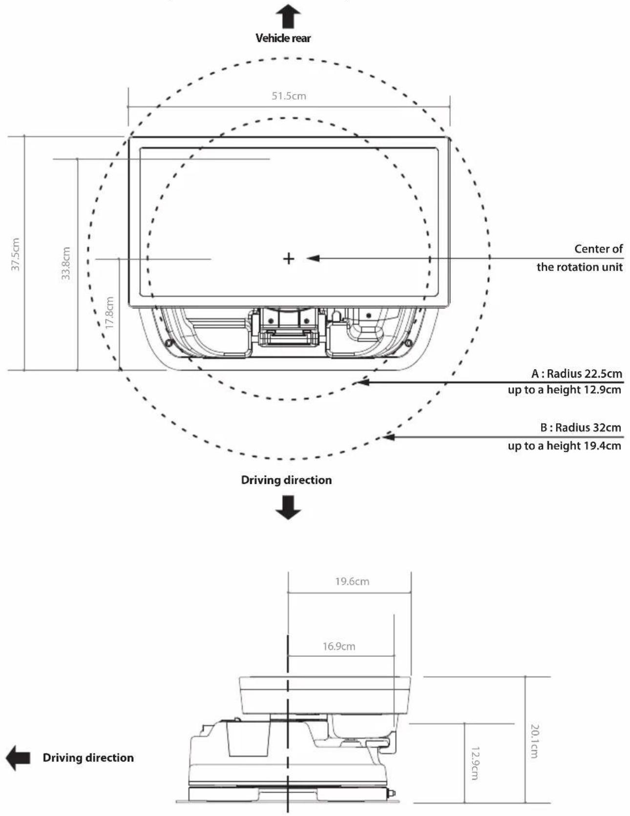
7-1. Dimension 12
7-2. Specifications 12
8. Caravan/Motorhome Installation
8-1. Required space for SNIPE3 13
8-2. Equipment for installation 14
8-3. Instruction for installation 14
1. General Information
1-1. Introduction
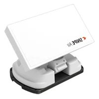
These instructions describe the functions and operation of SNIPE3, auto skew satellite system.
Correct and safe operation of the system can only be ensured by following instruction, both for installation and operation.
SNIPE3 is an intelligent satellite-TV reception system which can align itself towards a preset satellite automatically as long as the system is located within the footprint of the selected satellite.
SNIPE3 only occupies requisite space while it performs the necessary adjustments with slim and agile antenna body.
For general operation, please ensure that the system always has a clear view to the sky. In Europe, all satellites are in an approximate position on the equator. If the satellite's signal beam is interrupted by obstacles such as mountains, buildings or trees, the unit will not function and no TV signal will be received.
For more information on general use of this unit consult local dealer for assistance.
1-2. Proper use and operation
This product has been designed for portable use and fixed installation on vehicles with maximum speeds of 130 km/h. The unit is programmed to automatically aims at geostationary television satellites.
The power is supplied by a standard vehicle electrical system with a rated voltage of 12 Volts DC. For installations on the vehicle, use power input cable (cigarette lighter adaptor) to supply power. For portable use, optional power adaptor produced by SNIPE3 manufacturer must be used.
Use of the equipment for any other purpose to the one specified is not permitted.
Please also note the following instructions from the manufacturer :
- It is not possible to add or remove components on this product.
- The use of other components other than those originally supplied is not permitted.
- To complete installation, installer must strictly follow instruction in the supplied user manual. Failure to follow the user manual may cause damage to the unit or user's vehicle.
- The product does not require any regular maintenance; all service must be carried out at approved service centers.
- All relevant guidelines of the automotive industry must be observed and complied with.
- The equipment must only be installed on solid vehicle roofs.
- Avoid cleaning user's vehicle with the mounted satellite system in a drive-through car wash or a car wash with a high-pressure cleaner.
1-3. Safety notes
Please carefully read and follow the operating instructions in this manual and use the SNIPE3 for its intended purpose.
Upon installation of SNIPE3, please ensure the installation is done with supplied cables and ensure the cables are not modified in any way.
As the user of this equipment, be responsible for ensuring compliance with the relevant laws and regulations.
The manufacturer does not take liability for direct or indirect consequential damage of the system, motor vehicles or other equipment by reason of unsuitable battery usage or erroneous installation or wrong wire connection.
2. Contents
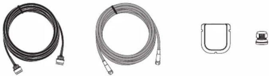
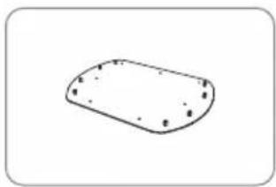
2-1. Accessory included
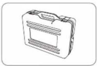
natural_image
Technical line drawing of a mechanical component or housing (no text or symbols)Main unit Mounting plate
natural_image
Simple line drawing of a rounded rectangular shape with small dots on its surface (no text or symbols)
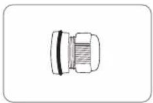
natural_image
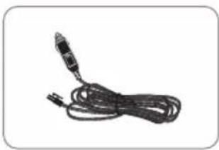
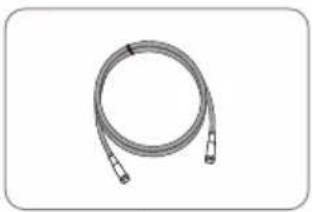
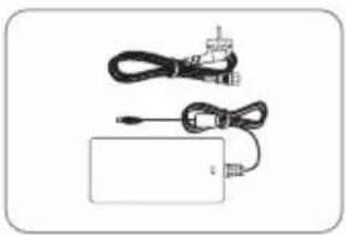
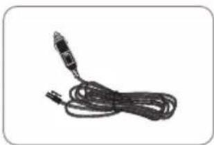
Coiled cable with a connector, no visible text or symbolsPower input cable (Cigarette lighter adaptor)
natural_image
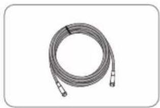
Coiled cable with two connectors, no text or symbols visibleSignal cable - 7m (x2 for optional twin outputs)
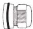
natural_image
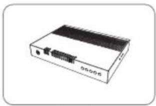
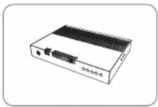
Illustration of a white electronic device with a black ventilation grille and ports (no text or symbols visible)Controller
natural_image
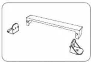
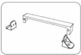
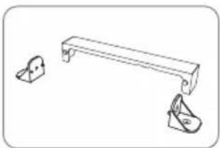
Simple line drawing of a bench with two separate bags, no text or symbols presentController bracket, Rear cable cover
natural_image
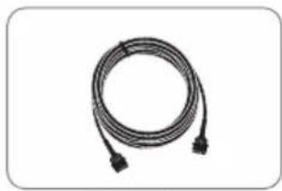
Coiled black cable with two connectors, no text or symbols visibleController cable-7m
natural_image
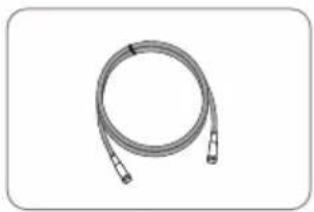
Coiled cable or hose with two connectors, no text or symbols visibleSTB cable - 1.5m
natural_image
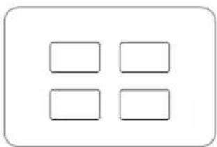
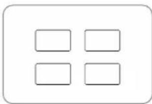
Simple diagram with four empty rounded rectangles arranged in a 2x2 grid inside a rounded rectangle (no text or symbols)Base pads
natural_image
Line drawing of a rectangular electronic device with ventilation slots and handle (no text or symbols)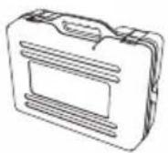

natural_image
Technical line drawing of a mechanical housing component (no text or symbols)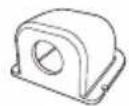
natural_image
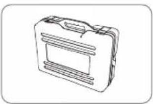
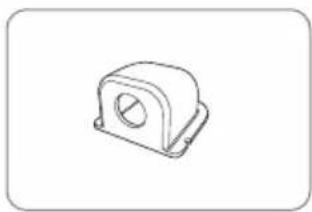
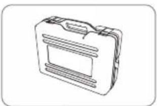
Simple line drawing of a mechanical connector or fitting (no text or symbols)Cable gland Carrying case Cable hold

natural_image
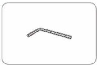
Simple 3D L-shaped line drawing with no text or symbolsAllen wrench
natural_image
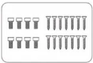
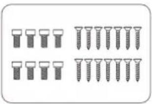
Illustration of screw and nut components (no text or symbols)Screw set M6 × 15 (8), M4 × 20(14)
User manual
natural_image
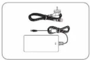
Illustration of a handheld electronic device with cables and connectors (no text or symbols)Power adaptor (Optional)
※ Power adaptor has to be purchased separate. Please ask to local dealer/shop for more information.
※ Only power adaptor produced by SNIPE series manufacturer is guaranteed and has to be used.
※ Actual components may differ from the above images.
※ The unit enables to have power from car battery. To make power input cable for direct connection, cut off cigarette lighter adaptor and peel off to take copper cables out.
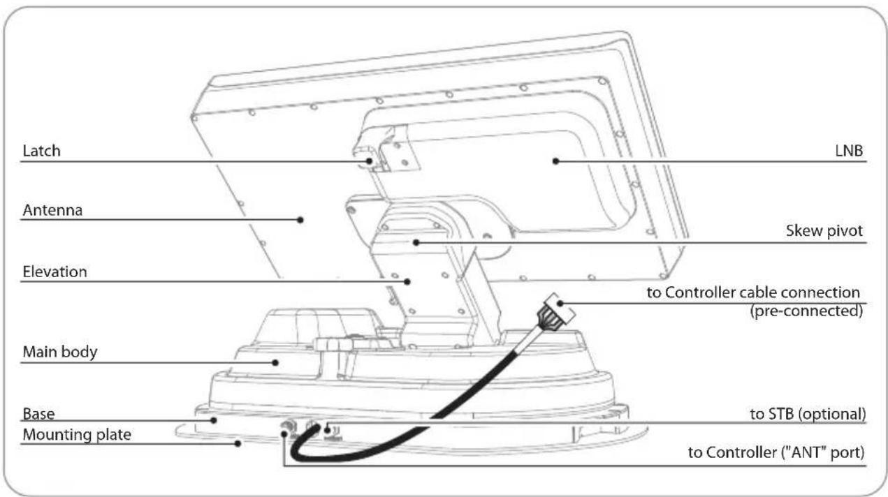
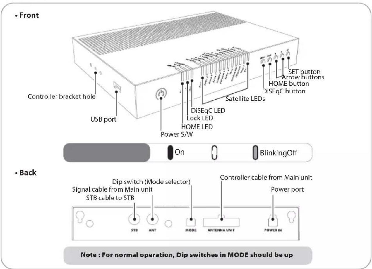
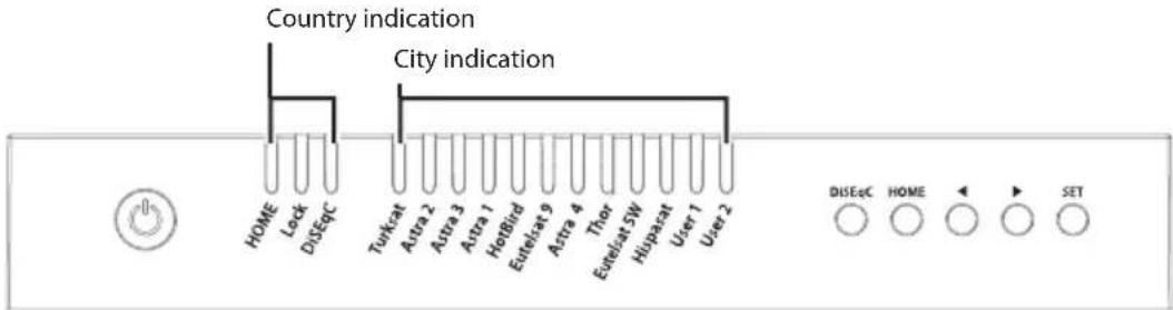
2-2. Name of parts
Main unit
Controller
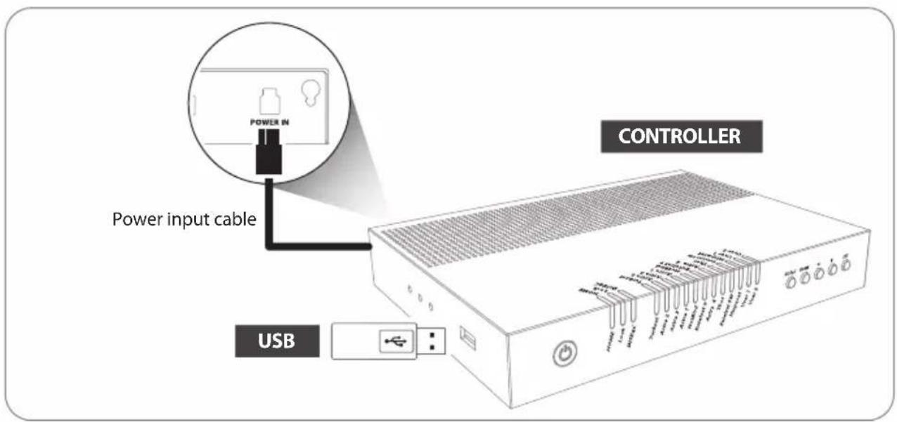
3. Operating Instruction
3-1. Connection diagram
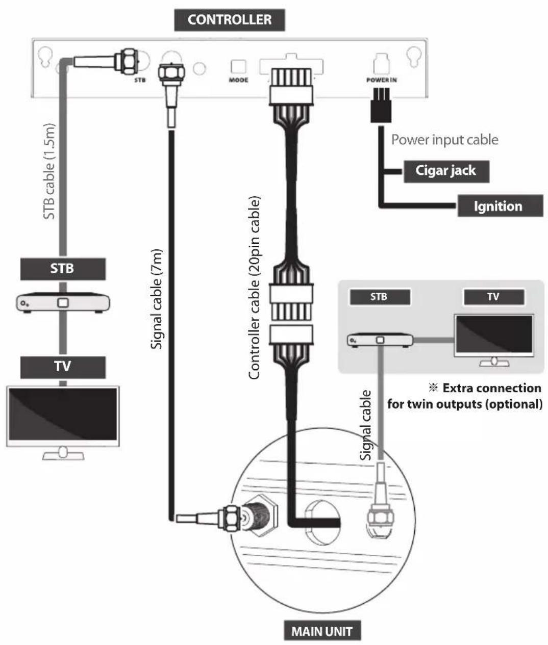
• There are two cable connections from the main unit to the controller
- Use controller cable (20pin) to connect the controller and the cable running out from the main unit
• Use STB cable (the shortest cable) to connect the controller and STB
- Please check the labels to use the correct cable for the job
- Please ensure the provided cables are used and not modified in anyway
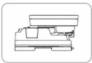
Portable use
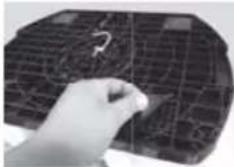
Attach four(4) base pads to the bottom of antenna base.
4. Functional description
※ Get ready to use
Default is set Automatic mode; both dip switches are up.
Customers should use only in Automatic mode.
Mode selector is for A/S, so it is not recommended by consumers to modify it arbitrarily.
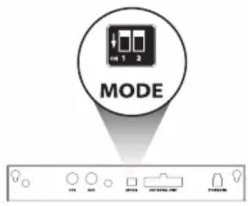
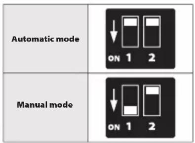
Warning
If the switch is handled in other than the Automatic mode, the unit does not operate normally.
Consumers should never do this, and if trouble is occurred in Manual mode, guarantee will not be provided.
4-1. Searching the satellite
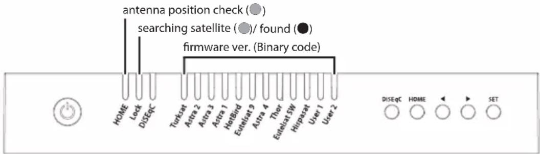
a. When the controller is turned on, some LEDs light indicate firmware version (It is made by binary code and for future service purpose)
b. Once the unit is ready to use, one of satellite LED is lit ON at default satellite
c. Go to the target satellite using arrows buttons and press SET button to confirm
d. Before satellite search, HOME LED blinks for antenna status(position) check (If antenna was not at HOME, antenna has to return to HOME first, LED may blink for a while)
e. Lock LED blinks during satellite search and becomes solid when the target satellite is found
f. After use and before travelling, press HOME button for HOME positioning
4-2. Back to HOME position & Turning off
A. Automatic
In some cases, the antenna is automatically stopped and sent to HOME position
a. If vehicle drives 25km/h or higher for 20 seconds
b. If ignition cable is connected and ignition signal is detected
B. Manual
After use and before travelling, the antenna has to be sent to HOME manually
For example :
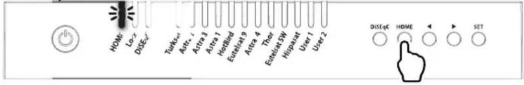
a. After use and before travelling, press HOME button to return the antenna back to HOME position and the unit is automatically turned off in 30 seconds
b. HOME LED blinks during HOME positioning and becomes solid when the antenna is at HOME
4-3. Special function
A. DiSEqC setting
Refer SNIPE3's pre-satellites for DiSEqC 1.1 when user setup at STB
a. Default setting for DiSEqC is OFF, DiSEqC LED is off
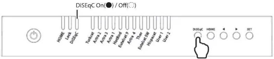
b. To switch the function ON/OFF, make sure that antenna is at HOME and press DiSEqC button for DiSEqC can be executed after pressing 2 seconds (See also DiSEqC LED status changes between ON and OFF)
c. For DiSEqC operating, user needs to assign DiSEqC satellites list at STB is in same order as above SNIPE3's pre-set list

NOTE
When antenna is not at HOME position, press SET button to activate DiSEqC function
B. GPS location manual setting
In case, antenna takes long time to search a satellite, there is the extra option of location setting for GPS.
a. Press and hold DiSEqC button then turn on the controller
b. Select the country from available options (four(4) countries) using DiSEqC/HOME buttons to change and confirm with controller LED ON as below table
| Country | HOME LED | Lock LED | DiSEqC LED |
| Germany | All LED OFF | ||
| France | ON | - | - |
| Netherland | - | ON | - |
| Italy | - | - | ON |
c. Select the city from available options using arrow buttons to change and confirm with LED ON as below table
| Germany France | Netherland Italy | |||
| Turksat | Aachen | Bayonne | Alkmar | Barletta |
| ASTRA2 | Augsburg | Brest | Apeldoorn | Bolzano |
| ASTRA3 | Bad Homburg | Caen | Enschede | Cagliai |
| ASTRA1 | Bamberg | Calais | Groningen | Carpi |
| Hot Bird | Berlin | Colmar | Hoogeveen | Catania |
| Etelsat 9 | Chemnitz | Nantes | Leeuwarden | Lecce |
| ASTRA 4 | Gottingen | Nizza | Nijmegen | Livorno |
| Thor | Hamburg | Paris | Roermond | Milano |
| Eutelsat 5W | Munster | Saint-Étienne | Rotterdam | Napoli |
| Hispasat | Offenburg | Dijon | Tilburg | Pesaro |
| USER1 | Passau | Toulouse | Utrecht | Pescara |
| USER | Neubrandenburg | Limoges | Emmeloord | Roma |
d. Once location setting is finished, press SET button to save
e. LEDs become off and controller will be automatically turned off
f. At next turn on, the antenna finds satellite with saved information

NOTE
GPS location manual setting is an option for instant satellite search, the antenna will search satellite based on GPS data after GPS is received
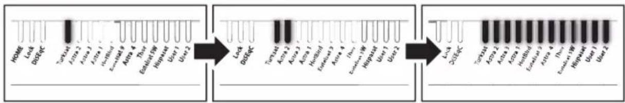
5. Software Upgrade

NOTE
USB 2.0 standard has to be only used for upgrade
※ Use FAT32 format USB only
- Transfer software program to a USB root folder (not belonging to any other folder) in an empty USB
i. Please go to website www.selfsat.com to download upgrade program (software)
ii. In case a controller does not recognize the USB drive, take the USB out and plug into a PC. Right click USB folder, go to "Properties" and check if the "File system" is FAT32. If not, right click USB folder again, go to "Format" and re-setup a file system to FAT32
- Ensure that the unit is turned off and plug the USB into USB port of controller
- Press and hold SET button then turn on the power
- During upgrade process, satellite LEDs are lit in sequence
For example :
flowchart
graph LR
    A["Gene 1"] --> B["Turkat"]
    C["Gene 2"] --> D["Acta 2"]
    E["Gene 3"] --> F["Acta 3"]
    G["Gene 4"] --> H["Hesb4"]
    I["Gene 5"] --> J["Elastot DW"]
    K["Gene 6"] --> L["Hesperat"]
    M["Gene 7"] --> N["User 1"]
    O["Gene 8"] --> P["User 2"]

    Q["Gene 9"] --> R["Turkat 9"]
    S["Gene 10"] --> T["Acta 10"]
    U["Gene 11"] --> V["Acta 11"]
    W["Gene 12"] --> X["Hesb4"]
    Y["Gene 13"] --> Z["Elastot DW"]
    AA["Gene 14"] --> AB["Hesperat"]
    AC["Gene 15"] --> AD["User 1"]
    AE["Gene 16"] --> AF["User 2"]

    AG["Gene 17"] --> AH["LysA"]
    AI["Gene 18"] --> AJ["DUSFC"]
    AK["Gene 19"] --> AL["Turkat 19"]
    AM["Gene 20"] --> AN["Aza 20"]
    AO["Gene 21"] --> AP["Aza 21"]
    AQ["Gene 22"] --> AR["Hesb4"]
    AS["Gene 23"] --> AT["Elastot DW"]
    AU["Gene 24"] --> AV["Hesperat"]
    AW["Gene 25"] --> AX["User 1"]
    AY["Gene 26"] --> AZ["User 2"]
Once upgrade is completed, controller starts to reboot5.
6. Troubleshooting
There are a number of common issues that can affect the signal reception quality or the operation of the unit. The following sections address these issues and potential solutions
A. No function when power on the controller
i. Check again all the cable connections have been made correctly.
- Connection between the power and controller.
- Connection between the controller and antenna. Make sure that the left port of the antenna should be connected to the controller.
ii. Check if the power input cable has been damaged.
iii. Check the battery polarities (+/-).
B. Fail to search the selected satellite
i. Satellite signals can be blocked or degraded by buildings, trees. Make sure there are no obstructions in a southward direction.
ii. Select another satellite as example Astra3, if this locks then select your desired satellite.
iii. Turn the unit off and then back on again and select desired satellite.
C. Mechanical problems
i. If the antenna does not move into desired position.
- Try to power OFF/ON again.
ii. If the antenna makes a noise whilst remaining static.
- Try to power OFF/ON again. If problem persists, please contact local dealer/shop for assistance.
D. Other issues
i. If the system has been improperly wired, it will not operate properly. Contact local dealer/shop for assistance of cable damage.
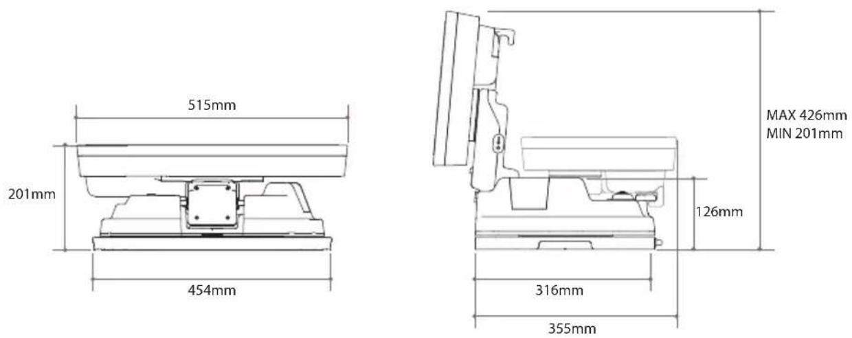
7. Specifications
7-1. Dimension
7-2. Specifications
| Input Satellite Frequency | 10.7 ~ 12.75 GHz | |
| Polarization | Vertical & Horizontal | |
| Antenna Gain | 33.7 dBi @ 12.7 GHz | |
| Size (W x D x H) | 515 × 355 × 201 mm | |
| Weight | 10.3 kg | |
| Min EIRP | 50 dBW | |
| Angle Range (Elevation, Azimuth, Skew) | 15° ~ 90°, 360°, -45° ~ +45° | |
| Satellite Searching Time | 120 seconds (AVG) | |
| Output | 1 / 2 output (Optional) | |
| LNB Output Frequency | 950 ~ 2,150 MHz | |
| L.O. Frequency | 9.75 / 10.6 GHz | |
| Operating Temperature | -30 °C ~ +60 °C | |
| Input Voltage | DC 12 V | |
| Power Consumption | 30 W (in searching) | |
8. Caravan/Motorhome Installation
8-1. Required space for SNIPE3
Please allow that there is enough space around SNIPE3 for flat antenna section to complete a full 360° scan of the sky and return to the HOME position
8-2. Equipment for installation
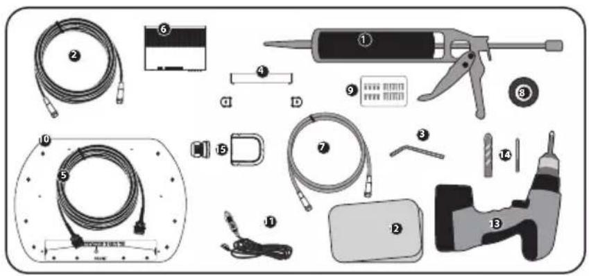
1 Silicone
2 Signal cable (7m)
3 Allen wrench
4 Controller bracket, Rear cable cover
5 Controller cable (7m)
6 Controller
7 STB cable (1.5m)
8 Masking tape
9 M6 × 15(8), M4 × 20(14)
10 Mounting plate
11 Power input cable (Cigarette lighter adaptor)
12 Cleaner
13 Power drill
14 2mm drill bit, over 25mm drill bit
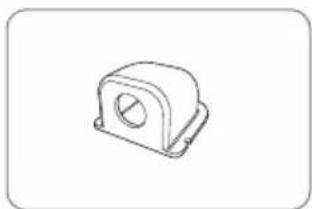
15 Cable holder & gland
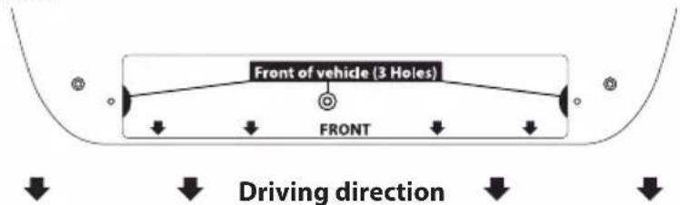
※ Mounting plate direction
8-3. Instruction for installation
A. Mounting plate installation on a vehicle roof
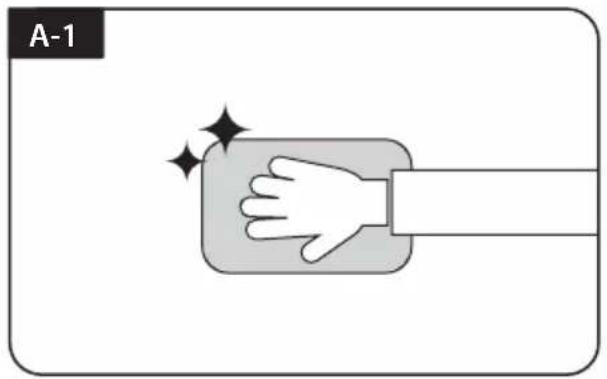
Clean the surface with cleaner
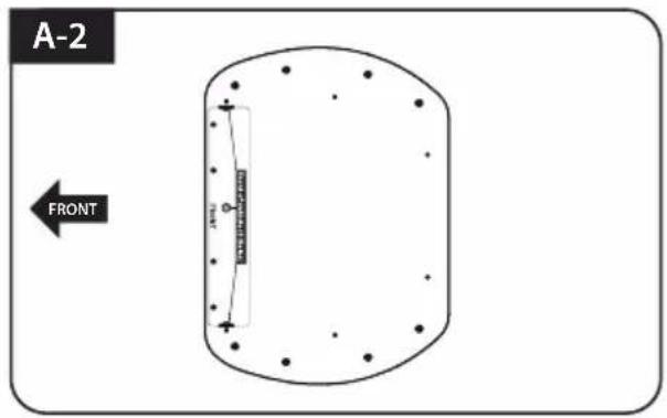
Locate mounting plate in the center of the vehicle roof
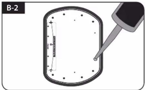
Attach masking tape outside of the mounting plate by 5mm away from the plate edges
natural_image
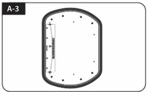
Diagram of a biological cell or membrane structure with no visible text or symbolsPut aside the mounting plate to apply silicone within the attached tape line but leave 2cm inward gap from the line
B. Assemble 7pcs of M4x20 bolt to fix the mounting plate
Place the mounting plate on the silicone and make 7 holes (2mm) with a power drill
Apply silicone on the holes
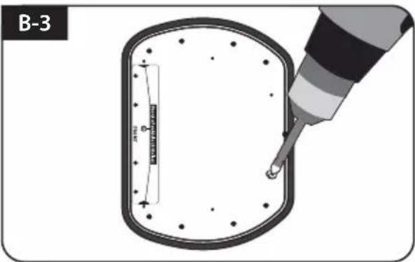
Assemble seven(7) of M4x20 screw Re-apply silicone to cover bolts assembled
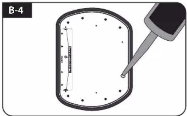
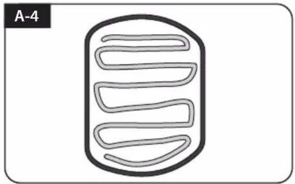
C. Apply silicone between mounting plate and masking tape
Apply silicone around mounting plate edges
Tidy silicone surface
Remove masking tape and allow to dry
Prepare to place the antenna on to the upright bolts
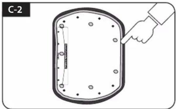
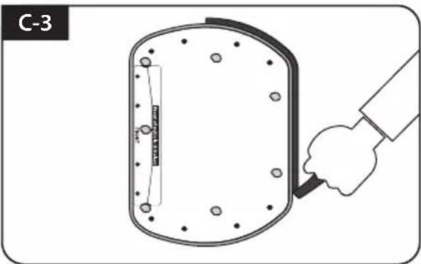
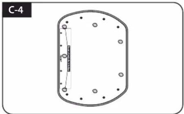
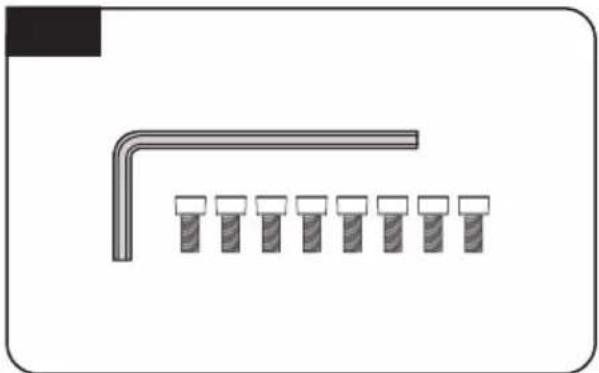
D. Fix mounting plate with 8 pcs of M6x15 bolt using allen wrench
natural_image
Pure diagram of a pipe with a bracket and six identical screw holes (no text or symbols)Parts required, allen wrench and eight(8) of M6×15 bolt
natural_image
Technical line drawing of a mechanical component with no visible text or symbolsPlace the antenna on mounting plate and tighten firmly each bolt by allen wrench
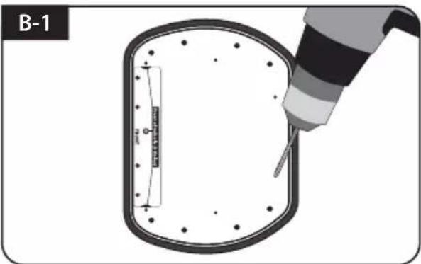
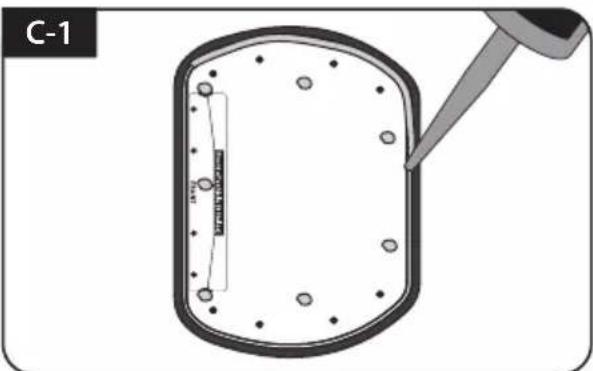
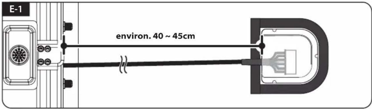
E. Cable holder installation 1
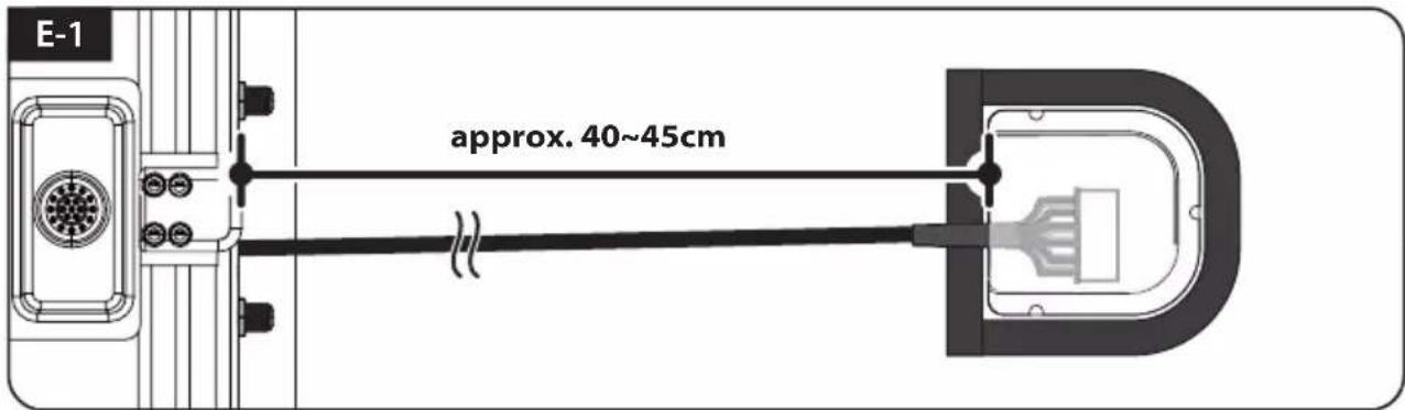
Place cable out from the antenna to have a rough idea of cable holder location (approx. 40\~45cm away from the antenna port) and apply masking tape 5mm way off from the outside of holder
natural_image
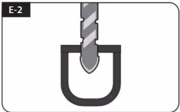
Diagram of a U-shaped tool inserted into a container, labeled E-2 (no text or symbols on the diagram itself)Drill a 25mm hole in the center of the tape marking
natural_image
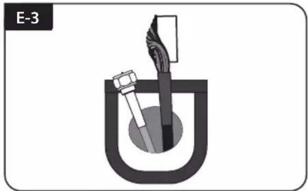
Diagram of a mechanical device with a U-shaped component and internal components (no text or symbols)Make sure that hole size is minimum so that the cable can pass through
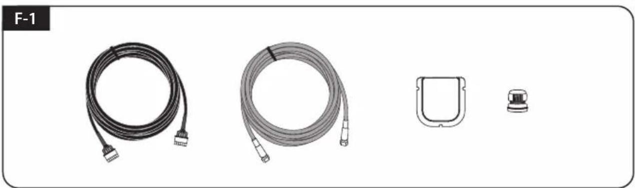
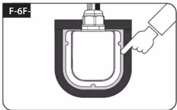
F. Cable holder installation 2
natural_image
Product line drawings of four different cable and connector components (no text or symbols)Signal cable, controller cable, cable holder and gland are required
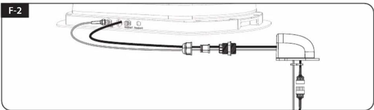
natural_image
Diagram of a cable connector assembly with connectors and ports, no text or symbols presentSet up required parts as above picture
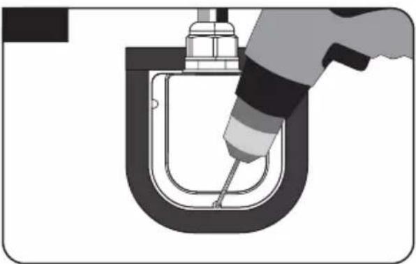
natural_image
Illustration of a hand using a tool to lift a U-shaped pipe (no text or symbols)Place the assembled cable holder inside the tape marking and drill three(3) of 2mm holes
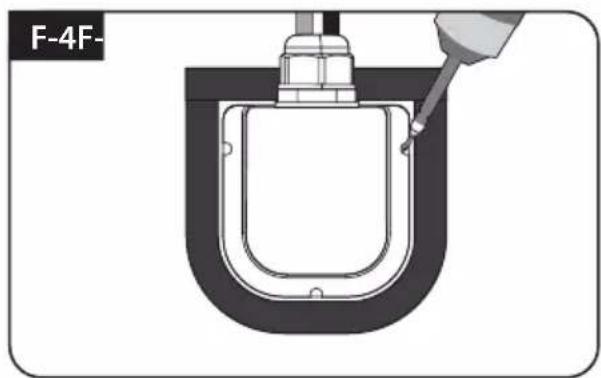
natural_image
Technical diagram of a U-shaped mechanical component with a tool inserted, no visible text or symbolsFix cable holder on the vehicle roof with three(3) of M4 x 20 screws on drill holes made
natural_image
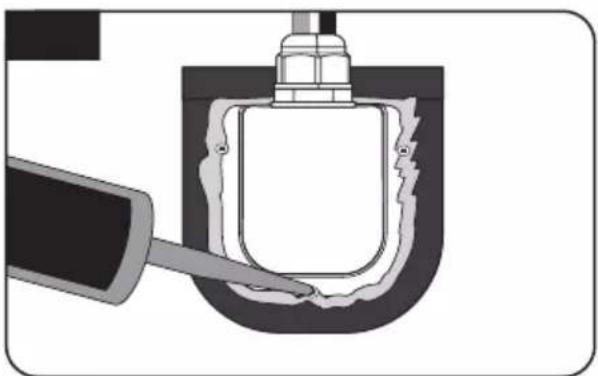
Cross-sectional diagram of a mechanical component with a tool inserted, showing internal structure and no text or symbols.Apply silicone around cable holder and on the top of screws for waterproof
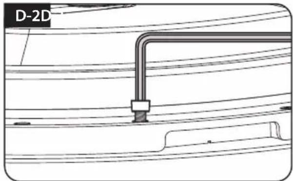
Connect cables to the ports of the antenna, remove masking tape and tidy silicone before dry
G. Controller installation
G-1
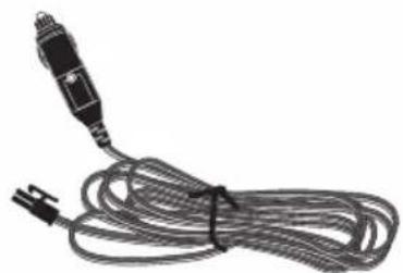
natural_image
Coiled electrical cable with a black connector and power plug (no text or symbols visible)Get Power input cable and plug into cigar lighter socket (12V outlet)
G-2
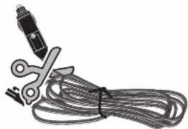
natural_image
Illustration of a pair of scissors cutting through coiled cables (no text or symbols)To source power from car battery, cut off cigar-jack connector to take inner three cables out and peel off each to take copper cable out
G-3
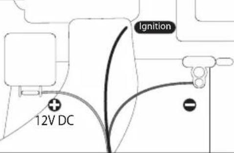
Match the power cables polarities to the battery polarities, red to red / back to black and white ignition cable to ignition port of the vehicle
G-4
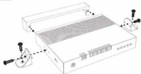
natural_image
Line drawing of a portable electronic device with ventilation grilles and control knobs (no text or symbols)Get Controller bracket, rear cable cover and four(4) M4x20 bolt
G-5
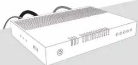
natural_image
Illustration of a white electronic device with ventilation grilles and ports (no text or symbols)Place controller and plug the cables to the controller (Power, signal and controller cables)
G-6
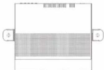
If desire to place the controller on the wall, fix the controller with provided bracket with four(4) screws
Once all cables are connected, connection part can be hidden using rear cable cover
Inhaltsverzeichnis
5. Program-Upgrade 10
natural_image
Technical line drawing of a mechanical component or housing (no text or symbols)natural_image
Simple line drawing of a rounded rectangular shape with small dots on its surface (no text or symbols)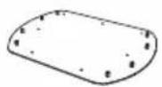

natural_image
Simple line drawing of a cable with a connector (no text or symbols)natural_image
Coiled cable with connectors, no visible text or symbols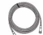
Signalkabe | - 7m
(X2 fur optionale Twin-Ausgange)
natural_image
Illustration of a rectangular electronic device with ports and connectors (no visible text or symbols)Controller
natural_image
Simple line drawing of a bench with two separate bags, no text or symbols presentnatural_image
Coiled black cable with two connectors, no text or symbols visibleControllerkabel - 7m
natural_image
Coiled cable or hose with two connectors, no text or symbols visibleSTB-Kabel - 1.5m

natural_image
Simple diagram with four empty rounded rectangles arranged in a 2x2 grid inside a rounded rectangle (no text or symbols)Basispolster
natural_image
Line drawing of a rectangular electronic device with ventilation slots and handle (no text or symbols)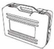
natural_image
Technical line drawing of a mechanical housing component (no text or symbols)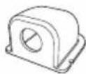
Kabelverschraubung Transportkoffer Kabe
natural_image
Simple 3D L-shaped line drawing with no text or symbolsInbusschlüssel

natural_image
Illustration of screw and nut components arranged in two rows (no text or symbols)M6 × 15 (8), M4 × 20(14)

Bedienungsanleitung
natural_image
Illustration of a handheld electronic device with cables and connectors (no text or symbols)Netzteil
(Optional)
natural_image
Hand holding a transparent cube with grid lines, no visible text or symbolsMobiler Einsatz
natural_image
Diagram of a biological structure with three parallel wavy lines inside a rounded rectangular frame, labeled A-4 (no text or symbols on the diagram itself)natural_image
Pure diagram of a pipe with a row of small pins, no text or symbols presentnatural_image
Technical line drawing of a mechanical component with no visible text or symbolsnatural_image
Diagram of a U-shaped tool inserted into a container, labeled E-2 (no text or symbols on the diagram itself)natural_image
Diagram of a U-shaped container with a tool inserted, showing internal components (no text or symbols)natural_image
Illustration of four different types of cable connectors and a small mechanical component (no text or symbols)natural_image
Technical line drawing of a cable connector assembly with connectors and connectors (no text or symbols)natural_image
Illustration of a hand using a tool to lift a U-shaped pipe (no text or symbols)natural_image
Technical line drawing of a mechanical component with a tool inserted, no visible text or symbolsnatural_image
Cross-sectional diagram of a mechanical component with a tool inserted, showing internal structure and no text or symbols.natural_image
Illustration of a hand pointing at a U-shaped container with a side panel (no text or symbols)G. Controller Installation
G-1

natural_image
Coiled cable with a black connector and power plug, no visible text or symbolsnatural_image
Illustration of a pair of scissors cutting through coiled cables (no text or symbols)natural_image
Technical line drawing of a portable electronic device with ventilation grilles and control knobs (no text or symbols)natural_image
Illustration of a portable electronic device with ventilation grilles and ports (no text or symbols)natural_image
Technical line drawing of a mechanical component or housing (no text or symbols)natural_image
Simple line drawing of a rounded rectangular shape with small dots on its surface (no text or symbols)
natural_image
Coiled black cable with a connector, isolated on white background (no text or symbols)natural_image
Coiled cable with two connectors, no text or symbols visiblenatural_image
Illustration of a white electronic device with multiple ports and a label '55006' on its side (no other text or symbols visible)Contrôleur
natural_image
Simple line drawing of a bench with two accessories (no text or symbols)natural_image
Coiled black cable with two connectors, no text or symbols visiblenatural_image
Coiled cable or hose with two connectors, no text or symbols visibleCâble STB - 1.5m
natural_image
Simple diagram with four empty rounded rectangles arranged in a 2x2 grid inside a rounded rectangle (no text or symbols)Coussin de la Base
natural_image
Line drawing of a rectangular electronic device with ventilation slots and a handle (no text or symbols)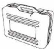
natural_image
Simple line drawing of a mechanical housing component (no text or symbols)
natural_image
Simple 3D L-shaped line drawing with no text or symbolsClé de montage
natural_image
Illustration of screw and nut components arranged in two rows (no text or symbols)M6 × 15(8), M4 × 20(14)

natural_image
Illustration of a handheld electronic device with cables and connectors (no text or symbols)natural_image
Hand interacting with a large grid map or map board (no visible text or symbols)natural_image
Illustration of a hand pressing down on a button with sparkles, labeled A-1 (no text or symbols on the diagram itself)natural_image
Diagram of a coiled structure with no text or symbols, labeled A-4 (no readable text or symbols)natural_image
Technical diagram of a circular mechanical component with bolt holes and a central rectangular feature (no text or symbols)natural_image
Pure diagram of a pipe elbow with six identical screw holes arranged in rows (no text or symbols)natural_image
Technical line drawing of a mechanical component with no visible text or symbolsE. Câble installation de support 1
natural_image
Diagram of a mechanical component with a U-shaped groove and a pointed tip, labeled E-2 (no text or symbols on the diagram itself)natural_image
Cross-sectional diagram of a mechanical or electrical component with no visible text or symbolsF. Câble installation du support 2
F-1