USER MANUAL Snipe Air Selfsat
2-1. Accessory included 4
2-2. Name of parts 5
3. Operating Instruction
3-1. Connection diagram 6
3-2. Functional description 7
3-3. Quick reference 10
-
Software Upgrade....11
-
Advanced Settings 12
6. Preparation of broadcasting on SAT>IP clients
6-1. How to set Wi-Fi network on devices 13
6-2. Configuration of the router via web 14
6-3.SAT>IP client setting 14
- Trouble Shooting 15
8. Specifications
8-1. Dimension 16
8-2. Specifications 16
9. Caravan / Motorhome Installation
9-1. Required space for SNIPE Air 17
9-2. Equipment for installation 18
9-3. Instruction for installation 18
1-1. Introduction
These instructions describe the functions and operation of SNIPE Air, auto skew satellite system.
Correct and safe operation of the system can only be ensured by following instruction, both for installation and operation.
SNIPE Air is an intelligent satellite-TV reception system which can align itself towards a preset satellite automatically as long as the system is located within the footprint of the selected satellite.
SNIPE Air only occupies requisite space while it performs the necessary adjustments with slim and agile antenna body.
For general operation, please ensure that the system always has a clear view to the sky. In Europe, all satellites are in an approximate position in the south. If the satellite's signal beam is interrupted by obstacles such as mountains, buildings or trees, the unit will not function and no TV signal will be received. For more information on general use of this unit consult local dealer for assistance.
Also, it is equipped with SAT>IP LNB and 802.11AC router, which enables user to use up to 8 different mobile devices simultaneously to watch satellite broadcasting channels.
This SNIPE Air is designed with most state-of-the-art technology, taking part of the worldwide trend set.
For more information on general use of this unit consult local dealer for assistance.
1-2. Proper use and operation
This product has been designed for portable use and fixed installation on vehicles with maximum speeds of 130 km/h. The unit is programmed to automatically aims at geostationary television satellites.
The power is supplied by a standard vehicle electrical system with a rated voltage of 12 or 24 Volts DC. For installations on the vehicle, use power input cable (cigarette lighter cable) to supply power. For portable use, optional power adaptor produced by SNIPE Air manufacturer must be used.
Use of the equipment for any other purpose to the one specified is not permitted.
Please also note the following instructions from the manufacturer :
- It is not possible to add or remove components on this product.
- The use of other components other than those originally supplied is not permitted.
- To complete installation, installer must strictly follow instruction in the supplied user manual. Failure to follow the user manual may cause damage to the unit or user's vehicle.
- The product does not require any regular maintenance; all service must be carried out at approved service centers.
- All relevant guidelines of the automotive industry must be observed and complied with.
- The equipment must only be installed on solid vehicle roofs.
- Avoid cleaning user's vehicle with the mounted satellite system in a drive-through car wash or a car wash with a high-pressure cleaner.
1-3. Safety notes
Please carefully read and follow the operating instructions in this manual and use the SNIPE Air for its intended purpose.
Upon installation of SNIPE Air, please ensure the installation is done with supplied cables and ensure the cables are not modified in any way.
As the user of this equipment, be responsible for ensuring compliance with the relevant laws and regulations.
The manufacturer does not take liability for direct or indirect consequential damage of the system, motor vehicles or other equipment by reason of unsuitable battery usage or erroneous installation or wrong wire connection.
2. Contents
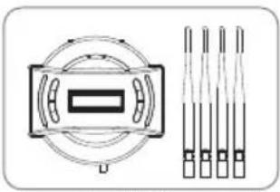
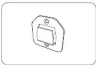
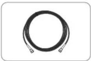
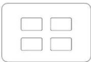
2-1. Accessory included
natural_image
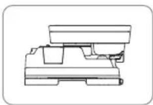
Technical line drawing of a mechanical component or housing (no text or symbols)
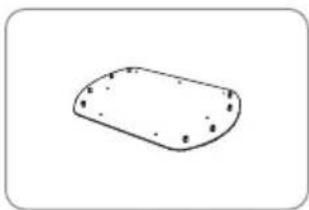
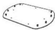
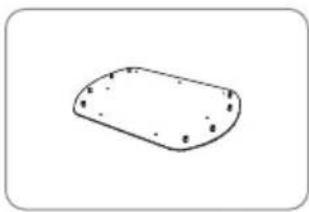
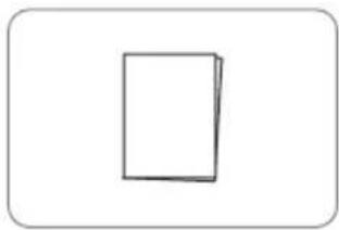
Main unit Mounting plate
natural_image
Simple line drawing of a rounded rectangular shape with small dots on its surface (no text or symbols)
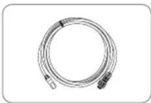
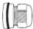
natural_image
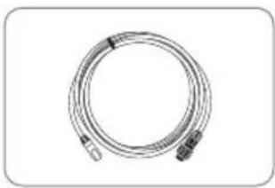
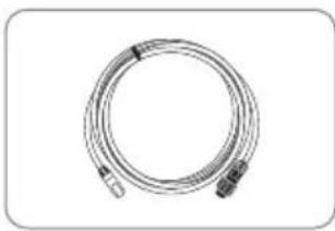
Coiled cable or hose with connectors, no visible text or symbols
SAT>IP LAN cable
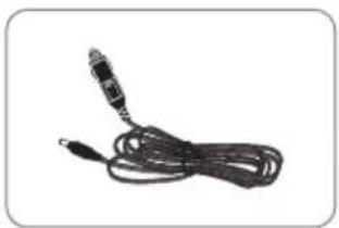
natural_image
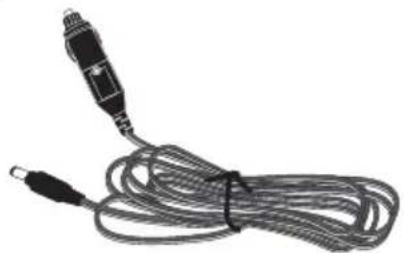
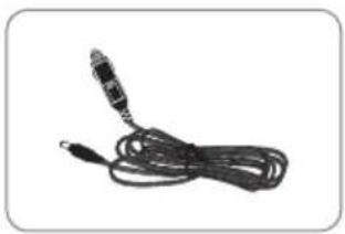
Coiled black cable with a metallic connector (no text or symbols visible)
Cigarette lighter adaptor
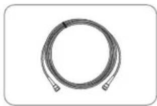
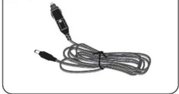
natural_image
Coiled cable or wire with two connectors, no text or symbols visible
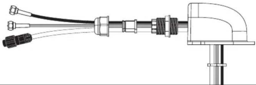
Receiver cable -12m, Grey
natural_image
Diagram showing a circular component with internal structure and three vertical rod-like structures aligned vertically (no text or symbols)
Controller / Wi-Fi antenna(4)
natural_image
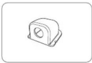
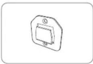
Simple line drawing of a mechanical component with a rectangular housing and mounting holes (no text or symbols)
Controller bracket
natural_image
Coiled black cable or hose with two connectors, no text or symbols visible
Controller cable - 12m, Black
natural_image
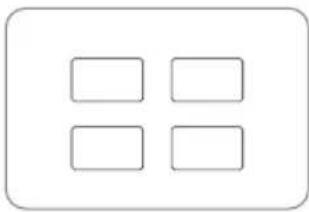
Simple diagram with four empty rounded rectangles inside a rounded rectangle (no text or symbols)
Base pads
natural_image
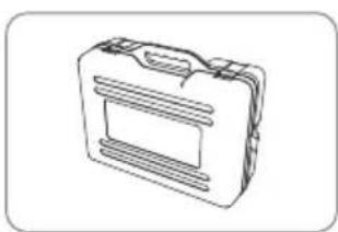
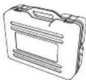
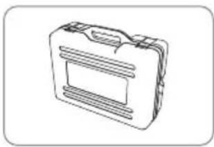
Line drawing of a briefcase with handle and ventilation slots (no text or symbols)
natural_image
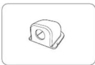
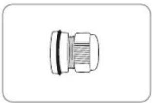
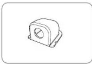
Technical line drawing of a mechanical bearing housing (no text or symbols)
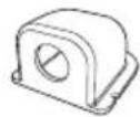

Cable gland Carrying case Cable hold

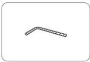
natural_image
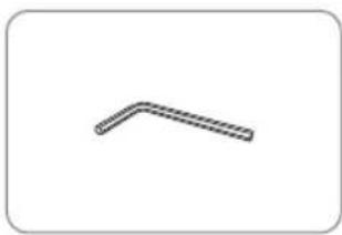
Simple 3D L-shaped pipe or angle bracket diagram without any text or symbols
Allen wrench
natural_image
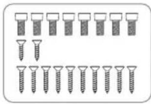
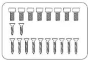
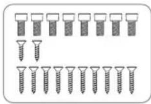
Illustration of multiple screw fasteners arranged in rows, with one showing a downward arrow (no text or symbols)
M6 × 15(8),
M4 × 16(2), M4 × 20(10)
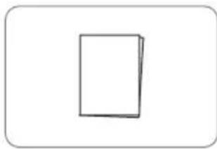
User manual
natural_image
Illustration of a clamp device with wires and a rectangular device (no text or symbols)
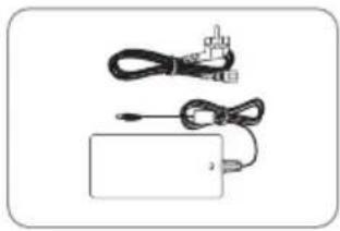
Power adaptor (Optional)
※ Power adaptor has to be purchased separate. Please ask to local dealer/shop for more information.
※ Only power adaptor produced by SNIPE series manufacturer is guaranteed and has been used.
※ Actual components may differ from the above images.
※ The unit enables to have power from car battery. To make power input cable for direct connection, cut off cigarette lighter adaptor and peel off to take copper cables out.
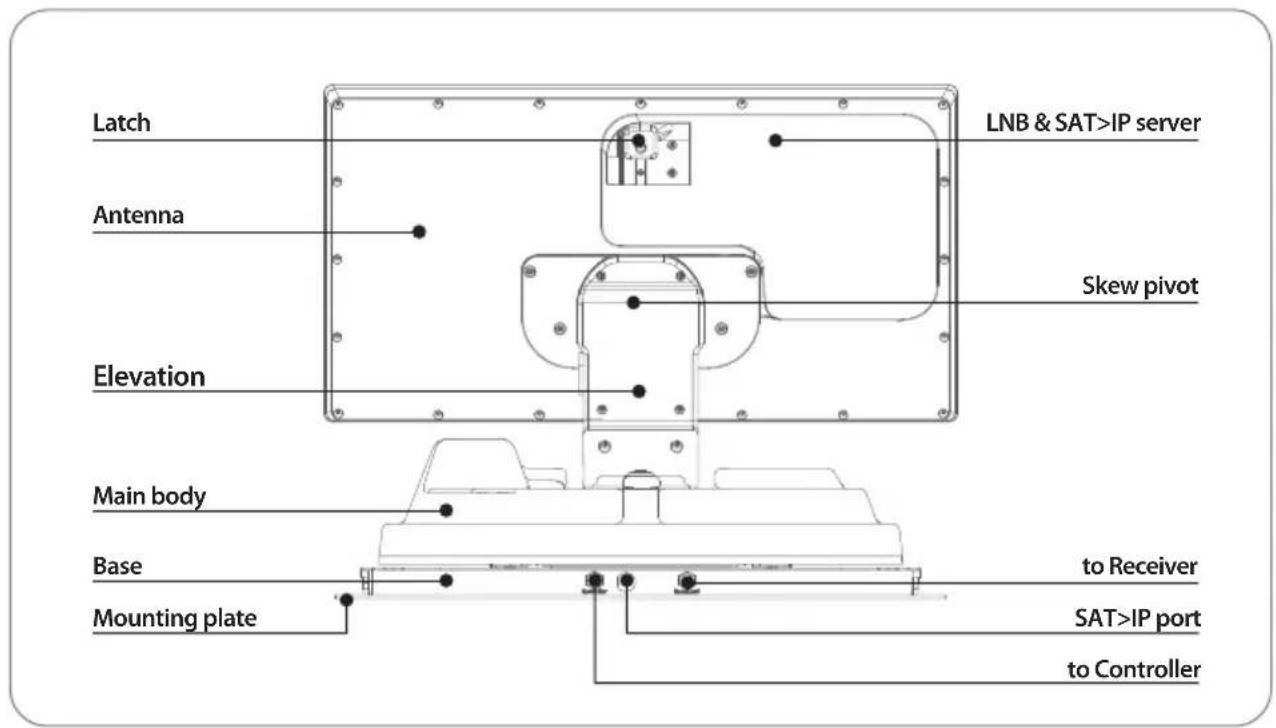
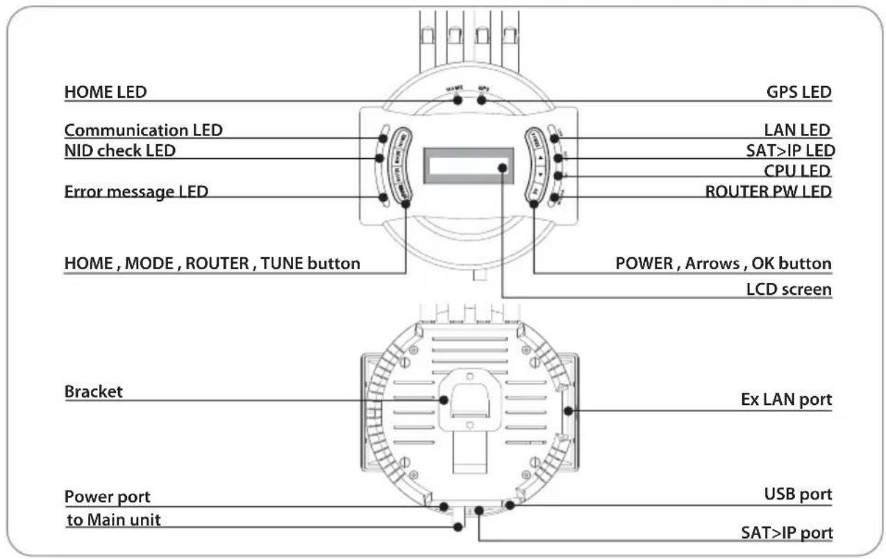
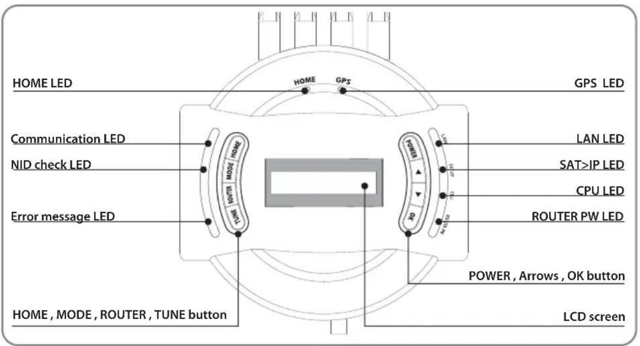
2-2. Name of parts
Main unit
Controller
3. Operating Instruction
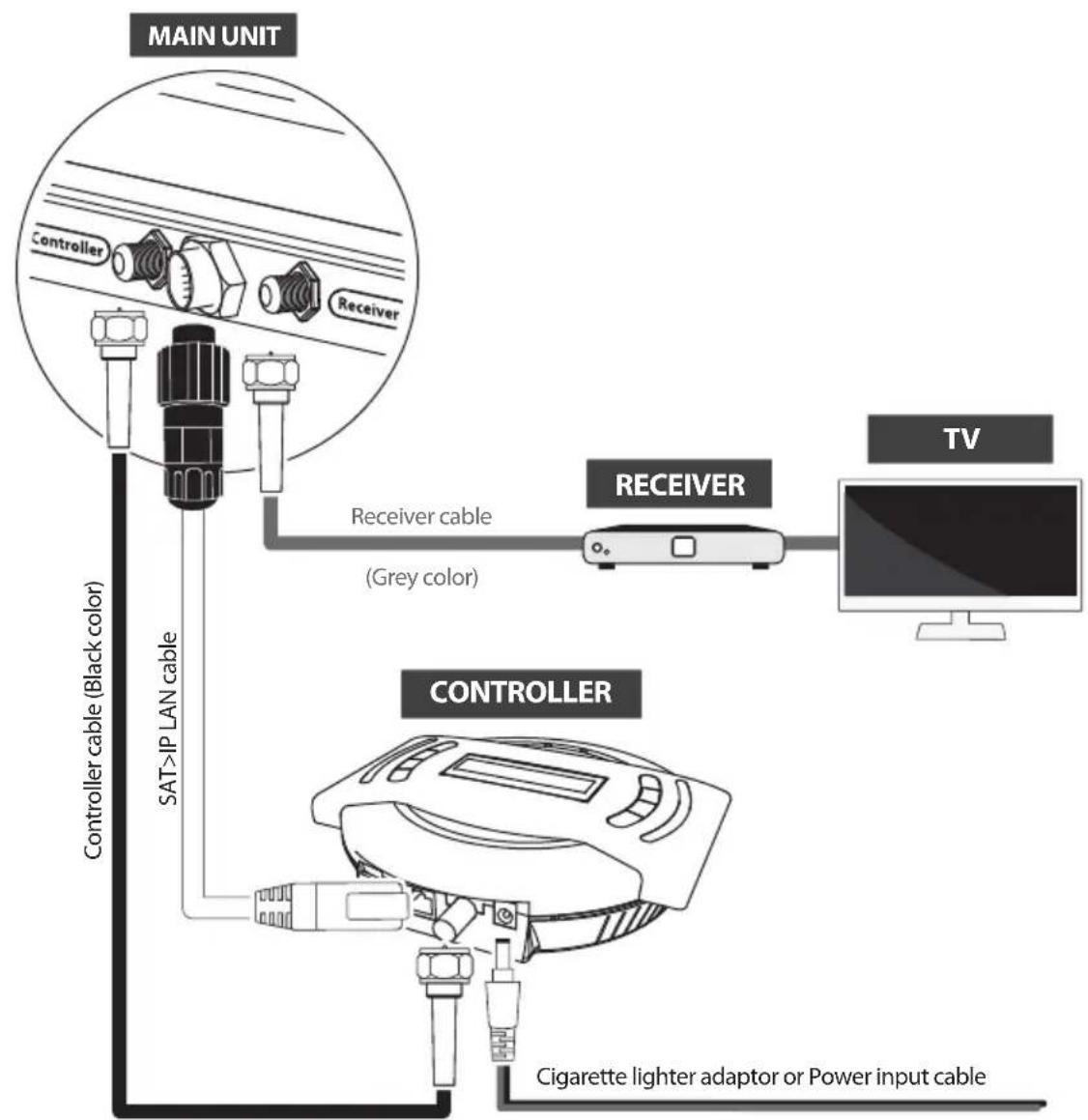
3-1. Connection diagram
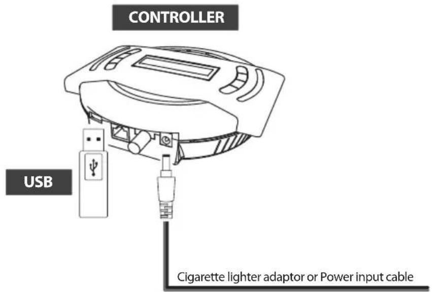
flowchart
graph TD
    A["MAIN UNIT"] --> B["Controller"]
    A --> C["Receiver"]
    B --> D["Controller cable (Black color)"]
    C --> E["Receiver cable (Grey color)"]
    D --> F["SAT>IP LAN cable"]
    E --> G["Cigarette lighter adaptor or Power input cable"]
    H["TV"] --> I["Monitor"]
Use black controller cable to connect the antenna to the controller. Controller cable looks similar to the receiver cable but has different color and labeling. Please check the labels to use the correct cable for the job. Please ensure the cables that are supplied are used and not modified in anyway.
NOTE

In order to watch the broadcast in Smart devices must be dedicated programs or application.
Please visit http://Satip.info for more information.
natural_image
Hand interacting with a digital display board showing grid patterns (no readable text or symbols)
Portable use
Attach four(4) base pads to the bottom of antenna base.
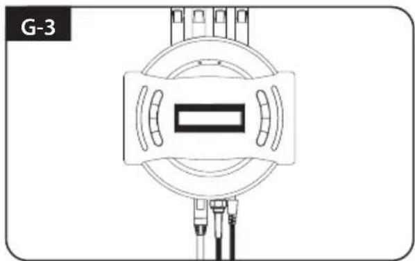
3-2. Functional description
Assemble controller Wi-Fi antenna
a. Get ready four (4) of Wi-Fi antennas to assemble to the controller.
b. Check the printed Wi-Fi range, 5G or 2.4G, at the bottom of antenna and on the top side of the controller to match.
c. Put and spin of each antenna to assemble the controller.
d. Hold the bottom of each antenna and spin tight till the end for firm assembly.
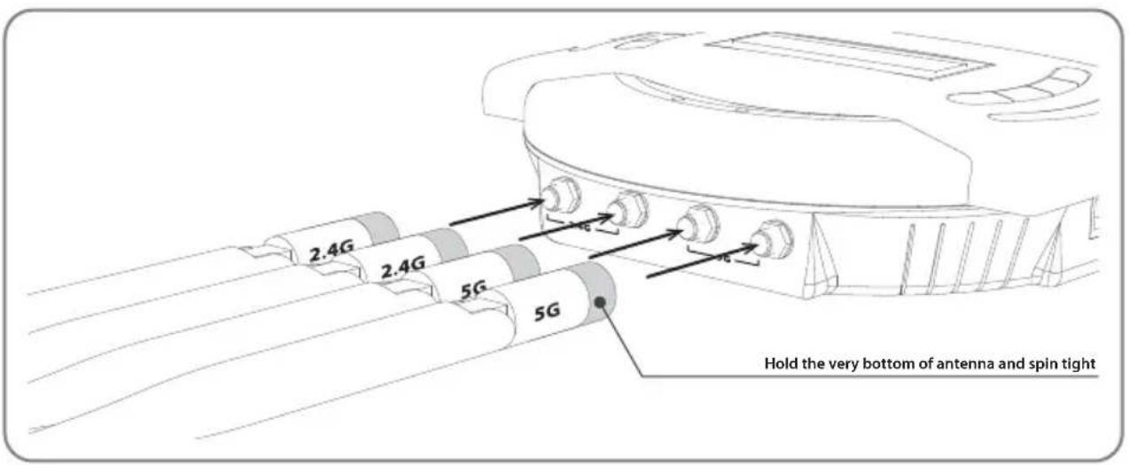
NOTE
Please mind that the Wi-Fi antenna should not be placed behind or underneath of metal material to ensure its performance.
1. Get ready to use
a. When the all cable connections are completed, press POWER to turn the unit on.
b. HOME LED will be solid this means the antenna is ready to go.
If the antenna did not go back to HOME position, HOME LED will continue to flash while antenna comes back to HOME. When the unit is ready, the default satellite "ASTRA1" or the last selected satellite will be shown on LCD screen of the controller.
NOTE
HOME position is when the antenna completely folded down and facing forward.
c. Communication LED will be solid when the unit is turned on.
(This light means antenna unit is communicating with controller correctly.)
d. ROUTER PW LED will be solid on since the unit is turned on. (This light means embedded router is ON)
e. CPU LED will flash since the unit is turned on.
(This light means embedded router is working properly.)
f. SAT>IP LED will flash temporarily to check operational channel when SAT>IP server is turned on. (This light will flash again when SAT>IP server is in actual operation streaming data out to smart devices.)
g. GPS LED flashes while searching for the current location. When GPS position is confirmed the LED will become solid.
h. Waiting until both HOME & GPS LED's are solid is recommended as this will allow the unit to find the selected satellite faster with more precise alignment accuracy.
i. If the searching operation starts before GPS becomes solid GPS LED will continue to flash even when the satellite is already locked. In this case, the unit may readjust skew once its current location is confirmed.
2. Selecting the satellite
a. Select the satellite which user wants to view using arrow buttons on the controller and press OK.
b. Network Identification (NID) check LED will flash and the antenna status will display "SEARCHING" and then "CHECKING" on LCD screen.
c. NID check LED will be solid once the satellite is found and then "SAT FOUND" will appear on LCD.
d. If wrong satellite is selected, move to the correct satellite name using arrows and press OK to confirm new satellite.
3. Back to HOME position & Turning off
a. After use and before travelling, press HOME to return the unit back to HOME position.
b. To fully turn off the unit, press and hold POWER for 5 seconds when the unit is at HOME position.
c. If user stays in a location for an extended period or wish to save power user can leave the unit up by simply turning off the unit by ROUTER button on the left side of controller. ROUTER PW LED will be off but signal stills comes through.
4. Special function 1 : FINE TUNE mode
FINE TUNE mode can be initialized when a selected satellite is found and user wants to increase the signal strength further.
a. Press TUNE to start FINE TUNE mode.
b. First TUNE is for AZ (Azimuth). Adjust antenna position using arrow buttons to find a new position providing better signal quality and press OK to set. The signal level will be displayed on the controller (Q_) or satellite receiver.
c. Repeat the same process of adjust the EL (Elevation) and SK (LNB skew).
d. To save new position of the satellite and exit, press TUNE button. Saved new position will be placed in the memory for the next turn on. But once vehicle moves or confirms new GPS location, the saved position will be reset.
5. Special function 2 : ERROR MESSAGE
Error message LED will be illuminated and the error message detail will be shown on LCD display, this will detail if there is a problem with main unit.
i. HOME POSITION error
If antenna does not come back to HOME position within the allowed time or the system does not recognise HOME position despite the antenna being back at HOME position (The Limit sensor is faulty).
ii. TUNNER error
If there is no response when searching the satellite due to a faulty tuner or its settings.
iii. MOVEMENT error
If the PRO MAX cannot move to correct position for some reason.
iv. COMMUNICATION error
If connection is lost between the unit and controller that lasts longer than 5 seconds.
6. Special function 3 : TEST mode
TEST mode can be initialised when either an error message is shown or the antenna is at HOME position.
a. Press MODE once to enter TEST mode and press OK.
b. Go to the available functions on LCD using the arrow buttons and press OK to select.
c. To exit, press MODE and unit will return to previous status.
7. Special function 4 : Ex LAN port
User are able to watch SAT>IP broadcasting channels on IP client or laptop by hard wired connection of LAN cable to Ex LAN port on the left side of the controller. If Ex LAN port is in use, LAN LED on the right side of controller will be solid on. (Extra LAN cable is not included in the package.)
3-3. Quick reference
- Press POWER to turn on the unit and select a satellite using arrow buttons and press OK.
- Wait until "SAT FOUND" is displayed on LCD and NID check LED(second LED on the left side) becomes solid.
- Now, the selected satellite has been locked and the TV channels will be shown on smart devices and TV.

WARNING
When user physically moves the unit, the unit must be returned to HOME position to prevent damage.

NOTE
The unit will be automatically folded back to HOME position if vehicle moves faster than 25km/h when the unit is powered.
4. Software Upgrade

NOTE
USB 2.0 standard has to be only used for upgrade
- Transfer software program to a USB root folder (not belonging to any other folder) in an empty USB.
i. Please go to website www.selfsat.com to download update program (software).
ii. In case a controller does not recognize the USB drive, take the USB out and plug into a PC. Right click USB folder, go to "Properties" and check if the "File system" is FAT32. If not, right click USB folder again, go to "Format" and re-setup a file system to FAT32.
- Ensure that the unit is turned off and plug the USB into USB port on the side of controller.
- Press and hold TUNE button then also press the POWER button.
- Unit will turn on and "USB connected, F/W Update mode" will be shown on LCD.
- Once "UPGRADE FINISHED" is shown, update is completed, remove the USB device.
5. Advanced Settings
Modify Transponder (TP) mode
i. Press MODE twice to enter "Modify TP mode" and press OK.
NOTE
To select and set numbers, use arrow buttons to see available options. The numbers adjust individually with the cursor and press OK to move to next option. This function is only used if the satellite operator changes all its parameters.
ii. Select the satellite to be modified, as example "00 XXXX(satellite name) \~ 11 XXXX" and press OK..
iii. Select TP number among "00\~02" and press OK. (Three TP's are programmed for each satellite)
iv. Repeat the same process by inputting data for NID (Network identity), FREQ (frequency) and SYMBOL (symbol rate).
v. Select type of signal DVBS or DVBS2 and press OK.
vi. Select polarization VER (vertical) or HOR (horizontal) and press OK.
vii. Select YES or NO to save and/or go back to first stage of TP Modify.
viii. To exit, press MODE and the unit will return to previous status.
ix. For manual TP data RESET, press MODE to enter TEST mode and press OK. Go to "TP RESET" and press OK among available functions on LCD using arrow buttons.
Restart the unit to apply the reset to next start up.
6. Preparation of broadcasting on SAT>IP clients
6-1. How to set Wi-Fi network on devices
A. On smart devices to watch SAT>IP broadcast
Go to "Setting" ▷ "Wi-Fi" ▷ Select "SATIPLINK2G" or "SATIPLINK5G"
NOTE
Only "SATIPLINK2G" may be found if devices does not support dual band Wi-Fi.
B. On laptop to watch SAT>IP broadcast
Go to "Setting" (Win10/8) / "Start" (Win7/Vista) ▷ "Control panel" ▷ Left click on "Network and Internet" ▷ "Networking and Sharing Center" ▷ "Network Connections" ▷ Select "SATIPLINK2G"
Go to "Start" ▷ "Control panel" ▷ Left click on "Network and Internet Connections"
▷ "Networking Connections" ▷ Select "SATIPLINK2G"
Click "Apple" menu ▷ "System Preferences" ▷ Click "Network" icon ▷ Select "SATIPLINK2G"
NOTE
PC needs to support Wi-Fi network and normally "SATIPLINK2G" is only shown on the Wi-Fi list.
If PC does support dual band Wi-Fi, both "SATIPLINK 2G" and "SATIPLINK 5G" will be available.
"SATIPLINK 5G" is recommended if possible to provide more stable reception of broadcasting.
Wi-Fi name would be shown as "SATIPLINK 2Gxx" or "SATIPLINK 5Gxx", ends with extra numbers.
※ If "SATIPLINK 2G is not found on the Wi-Fi list, please check below.
Go to "Setting" (Win10/8) / "Start" (Win7/Vista) ▷ "Control panel" ▷ Left click on "Network and Internet" ▷ "Networking and Sharing Center" ▷ "Change Adapter Settings" (Win10/8/7) / "Manage Network Connections"(Vista) ▷ Right click "Local Area Connection" ▷ "Properties" ▷ Double click on "Internet Protocol Version 4 (TCP/IPv4)" ▷ "Obtain an IP address automatically" ▷ "Obtain DNS server address automatically" ▷ "OK"
Click "Apple" menu ▷ "System Preferences" ▷ Click "Network" icon ▷ "Ethernet" in the left side box ▷ "Advanced" in the lower right corner ▷ Select "TCP/IP" in the top option ▷ Pull down the menu and click "Configure IPv4" ▷ "Using DHCP" ▷ "OK" ▷ "Apply"
6-2. Configuration of the router via web
A. After selecting SATIPLINK 2G(2.4G) / SATIPLINK 5G(5G) Wi-Fi network, open Ethernet browser and go to http://satiplink.com (default web address) to visit router's web management page.
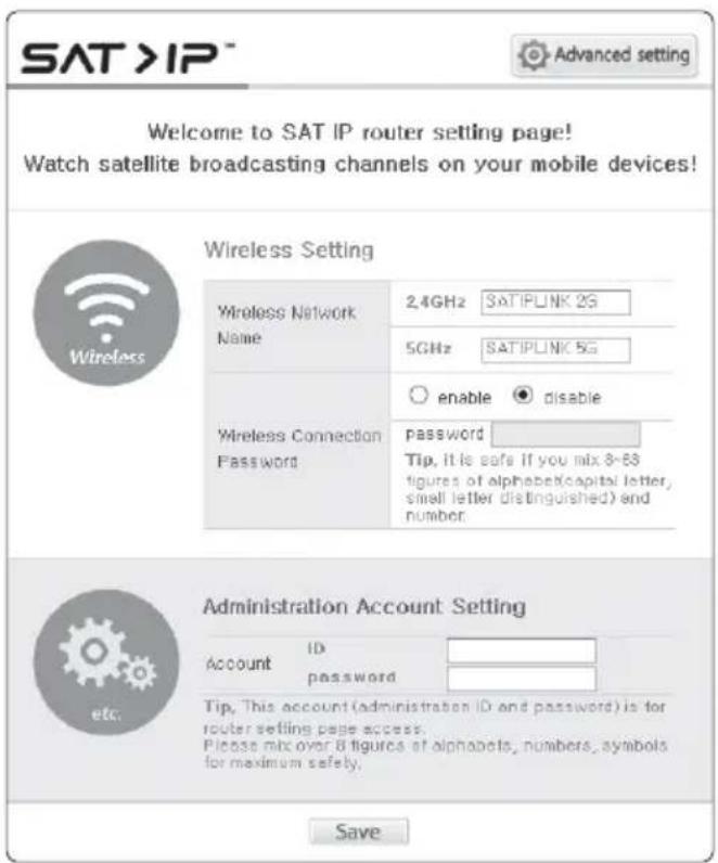
1) To setup, configure your wireless network name (SSID) and password.
Default password is "SATIPLINK25", and must be in all capital.
2) "Save" to take changed settings.
3) For further settings, click "Advanced setting" on the top right of the page.
- Change the router's password
- Manage the router's settings
- Change the wireless channel if the internet connection is not good enough
NOTE
※ http://satiplink.com page will only be available after access of SATIPLINK2G (or 5G) Wi-Fi network through router embedded in SNIPE Air.
6-3. SAT>IP client setting
A. SAT>IP App for iOS/Android smart devices
Go to Apple store or Google Play to download a SAT>IP App such as "Elgato SAT>IP" which allows user to receive decrypted programs and then run App
B. SAT>IP PC viewer for Microsoft Windows
Go to www.satip.info to download a SAT>IP program such as "DVBViewer". Within the options menu user can choose user's SAT>IP server and change the settings.
C. SAT>IP TV or TV connected from SAT>IP STB
Embedded software enables in TV or STB to receive IP streams from SAT>IP server
D. TV with SAT>IP Wi-Fi Dongle
Connected SAT>IP Wi-Fi Dongle enables TV to receive IP streams from SAT>IP server
NOTE
Go to www.satip.info to have the latest information for SAT>IP applications and PC program.
7. Trouble Shooting
There are a number of common issues that can affect the signal reception quality or the operation of the unit. The following sections address these issues and potential solutions.
A. No function when power on the controller
i. Check again all the cable connections have been made correctly.
- Connection between the power and controller.
- Connection between the controller and antenna. Make sure that the left port of the antenna should be connected to the controller.
ii. Check if the power input cable has been damaged.
iii. Check the battery polarities (+/-).
B. Fail to search the selected satellite
i. Satellite signals can be blocked or degraded by buildings, trees. Make sure there are no obstructions in a southward direction.
ii. Select another satellite as example Astra3, if this locks then select your desired satellite. ie Astra1.
iii. Turn the unit off and then back on again and select desired satellite.
C. Mechanical problems
i. If the antenna does not move into desired position.
- Try to power OFF/ON again.
ii. If the antenna makes a noise whilst remaining status.
- Try to power OFF/ON again. If problem persists, please contact local dealer/shop for assistance.
D. Other issues
i. If the system has been improperly wired, it will not operate properly. Contact local dealer/shop for assistance of cable damage.
E. Not able to watch SAT>IP broadcasting channels on users devices
i. Make sure that the unit is locked the satellite correctly.
ii. Check Wi-Fi connection between the unit and users' devices.
iii. Make sure that SAT>IP clients such as mobile app, IP STB, IPTV, etc., works properly.
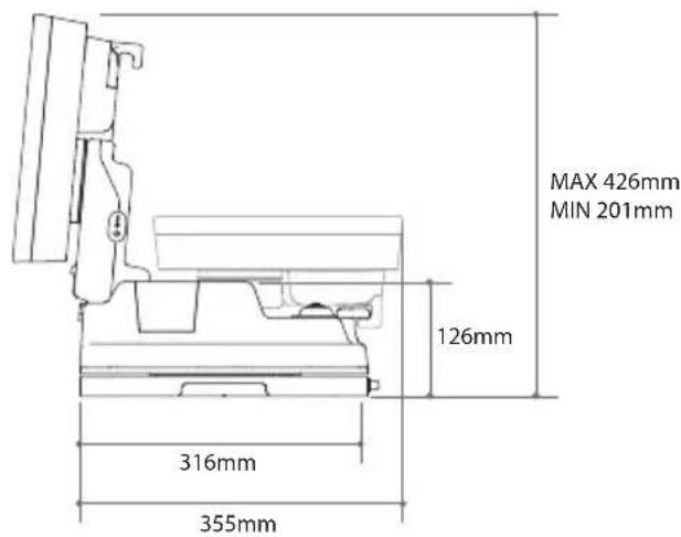
8. Specifications
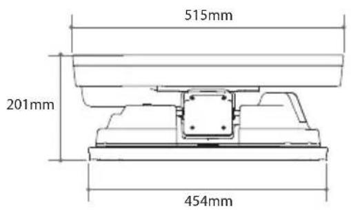
8- 1. Dimension
8-2. Specifications
a. Antenna
| Input Satellite Frequency | 10.7 ~ 12.75 GHz |
| Polarization | Vertical & Horizontal |
| Antenna Gain | 33.7 dBi @ 12.7 GHz |
| Size ( W x D x H ) | 515 × 355 × 201 mm |
| Weight | 10.9 kg |
| Min EIRP | 50 dBW |
| Angle Range (Elevation , Azimuth , Skew) | 15°~90°, 360°, -45°~+45° |
| Satellite Searching Time | 120 seconds (AVG) |
| Output | 1 Legacy |
| LNB Output Frequency | 950 ~ 2,150 MHz |
| L.O. Frequency | 9.75 / 10.6 GHz |
| Operating Temperature | -30 °C ~ +60 °C |
| Input Voltage | DC 12 ~ 24 V |
| Power Consumption | 100 W (in searching) |
| Wirelessly Operating Channels | 8 channels at the same time |
| Wireless connection | IEEE 802.11 AC compliance |
b. Router (Embedded in controller)
| CPU | RTL8197DN + RTL8192ER + RTL8812AR |
| Flash / DRAM | 8MB (SPI Serial Nor Flash) / 8MB (SPI Serial Nor Flash) |
| Wired LAN Interface | 10/100/1000 Base-T Port 2ea |
| Wireless LAN Interface | 2.4G : 802.11b/g/n (2T/2R) , MAX 300Mbps |
| 5G : 802.11a/n/ac (2T/2R) , MAX 867Mbps |
| Frequency Band | 5 GHz/2.4 GHz (20 / 40 / 80 MHz Bandwidth Channel bonding) |
| Antenna | 2.4G : 4dBi Dipole 2ea MIMO Technology |
| 5G : 5dBi Dipole 2ea MIMO Technology |
| Operation / Storage Temp. | 0°C ~ 40°C (operating) / 0°C ~ 50°C (storage) |
| Operation / Storage Humidity. | 80% (operating) / 90% (storage) |
| Special Function | P.S.E (Power Sourcing Equipment, supported 802.11at) |
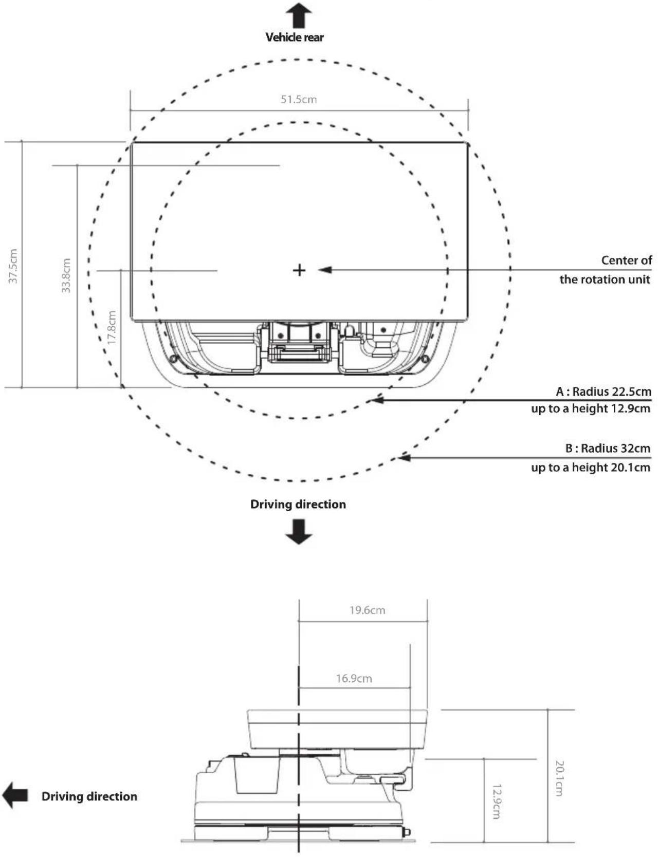
9. Caravan / Motorhome Installation
9-1. Required space for SNIPE Air
Please allow that there is enough space around SNIPE Air for flat antenna section to complete a full 360° scan of the sky and return to the HOME position.
9-2. Equipment for installation
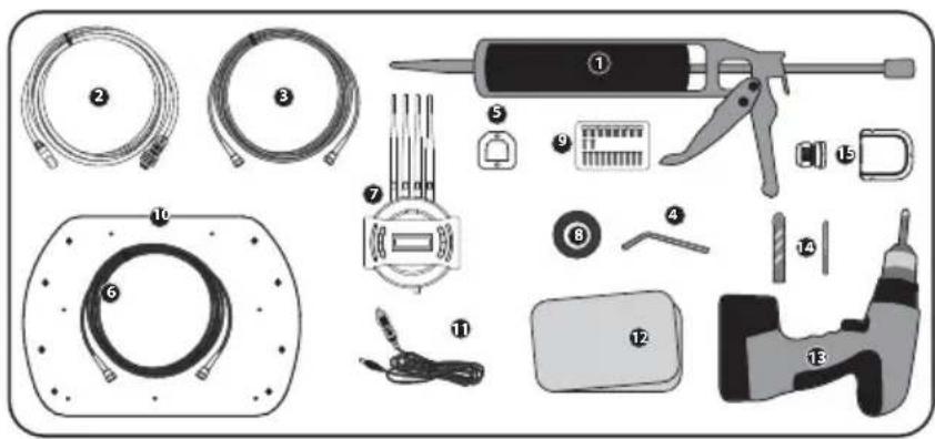
1 Silicone
2 SAT>IP LAN cable
3 Receiver cables
4 Allen wrench
5 Controller bracket
6 Controller cable
7 Controller
8 Masking tape
9 M6 × 15(8), M4 × 16(2), M4 × 20(10)
10 Mounting plate
11 Cigarette lighter adaptor (Power input cable)
12 Cleaner
13 Power drill
14 2 mm drill bit, over 20 mm drill bit
15 Cable holder & gland
※ Mounting plate direction
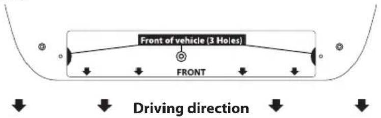
9-3. Instruction for installation
A. Mounting plate installation on a vehicle roof
A-1

natural_image
Illustration of a hand pressing down on a rectangular object with sparkles (no text or symbols)
Clean the surface with cleaner
A-2

natural_image
Simple geometric shape with a rounded corner and scattered dots inside, no text or symbols present.
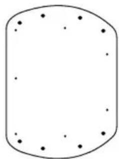
Locate mounting plate in the center of the vehicle roof
A-3
natural_image
Simple geometric shape with rounded corners and scattered dots, no text or symbols present.
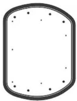
Attach masking tape outside of the mounting plate by 5 mm away from the plate edges
A-4
natural_image
Abstract diagram of nested wavy lines within a rounded rectangular boundary (no text or symbols)
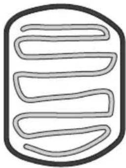
Put aside the mounting plate to apply silicone within the attached tape line but leave 2 cm inward gap from the line
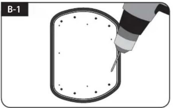
B. Assemble 7pcs of M4x20 bolt to fix the mounting plate
natural_image
Illustration of a tool tiping a rounded rectangular object with dots, labeled B-1 (no text or symbols on the object itself)
Place the mounting plate on the silicone and make 7 holes (2 mm) with a power drill
natural_image
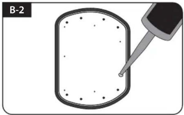
Diagram showing a dropper tip interacting with a rectangular object, labeled B-2 (no text or symbols on the diagram itself)
Apply silicone on the holes
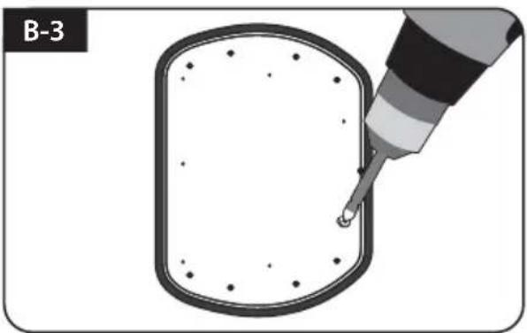
natural_image
Diagram showing a dropper injecting liquid into a rectangular container (no text or symbols)
Assemble seven(7) of M4x20 screw Re-apply silicone to cover bolts assembled
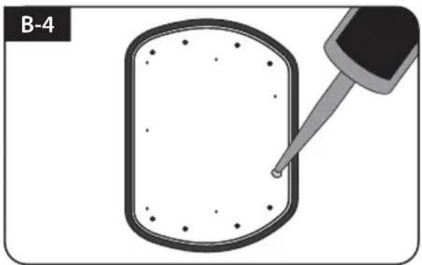
natural_image
Diagram showing a dropper tip interacting with a rectangular object, labeled B-4 (no text or symbols on the diagram itself)
C. Apply silicone between mounting plate and masking tape
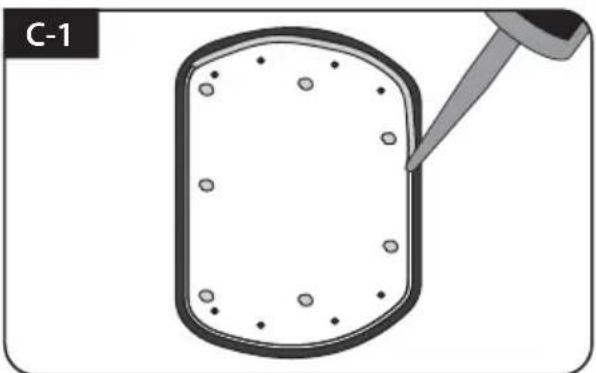
natural_image
Diagram of a dropper tip dispensing liquid into a rectangular container with scattered particles (no text or symbols)
Apply silicone around mounting plate edges
natural_image
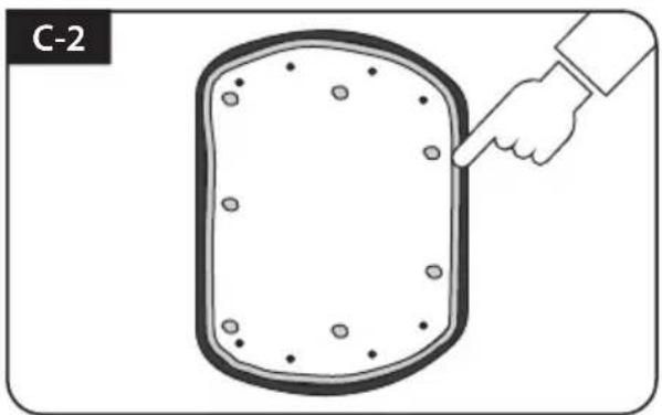
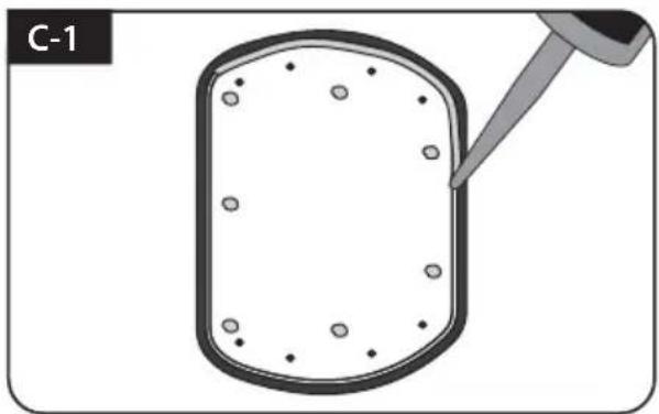
Illustration of a hand pointing at a rectangular object with circular holes, labeled C-2 (no text or symbols on the object itself)
Tidy silicone surface
natural_image
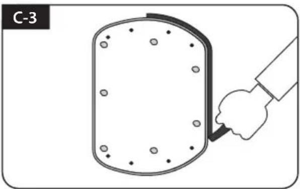
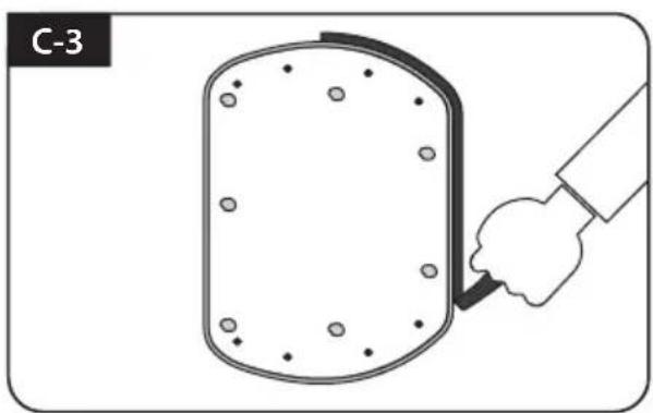
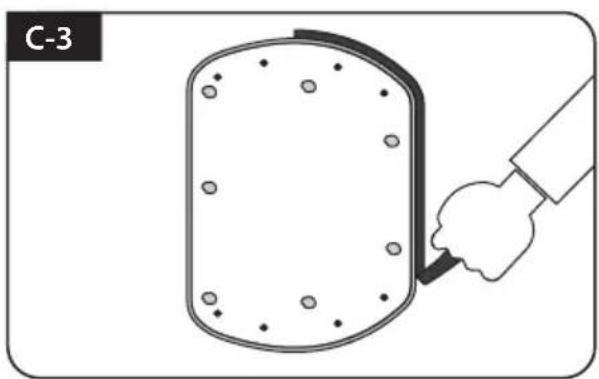
Illustration of a hand holding a tool interacting with a circular object, labeled C-3 (no text or symbols on the object itself)
Remove masking tape and allow to dry
natural_image
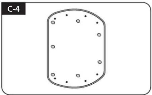
Simple diagram of a rounded rectangular shape with scattered circular holes, labeled C-4 (no text or symbols within the shape)
Prepare to place the antenna on to the upright bolts
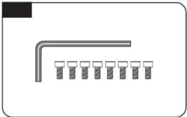
D. Fix mounting plate with 8 pcs of M6x15 bolt using allen wrench
natural_image
Pure diagram of a mechanical component with a bent pipe and seven evenly spaced pins (no text or symbols)
Parts required, allen wrench and eight(8) of M6×15 bolt
natural_image
Technical line drawing of a mechanical component with no visible text or symbols
Place the antenna on mounting plate and tighten firmly each bolt by allen wrench
E. Cable holder installation 1
natural_image
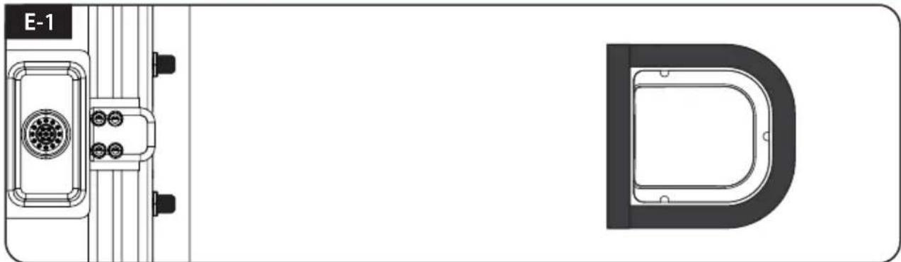
Technical diagram showing a mechanical component with labeled section E-1 and a D-shaped outline (no text or symbols beyond labels)
Place cable holder 30 cm away from the rear center of the antenna. Apply masking tape 5 mm from away the outside of holder
natural_image
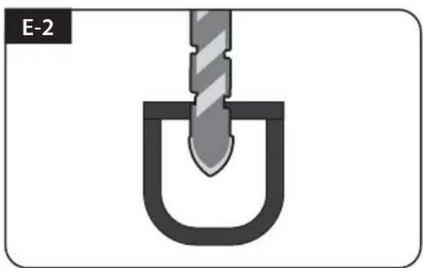
Diagram of a U-shaped tool with a pointed tip inserted into a container, labeled E-2 (no text or symbols on the diagram itself)
Drill a 20 mm hole in the center of the tape marking
natural_image
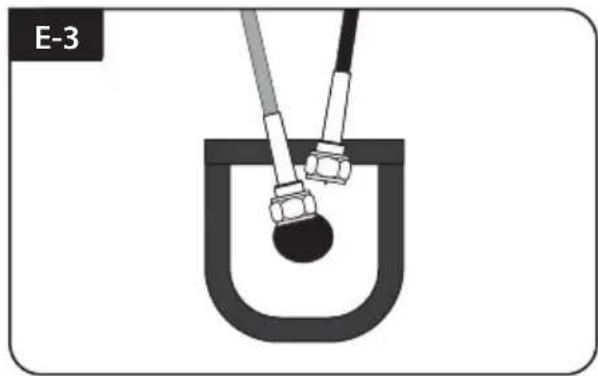
Diagram of a U-shaped tube with two probes inserted into it, no text or symbols present
Make sure that hole size is minimum so that the cable can pass through
F. Cable holder installation 2
natural_image
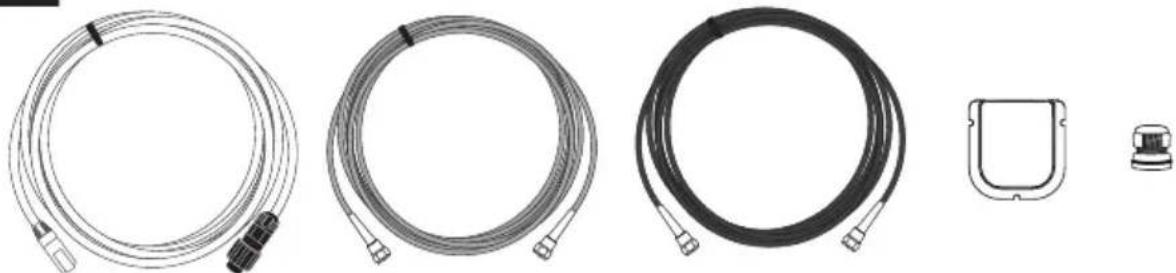
Product line drawings of various cable and connector components (no text or symbols)
SAT>IP LAN cable, controller cable, receiver cable, cable holder and gland are required
natural_image
Technical line drawing of a mechanical or electrical component with connectors and a vertical support (no text or symbols)
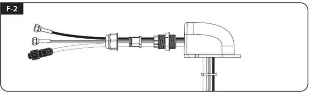
Set up required parts as above picture
natural_image
Illustration of a hand using a tool to lift a U-shaped pipe (no text or symbols)
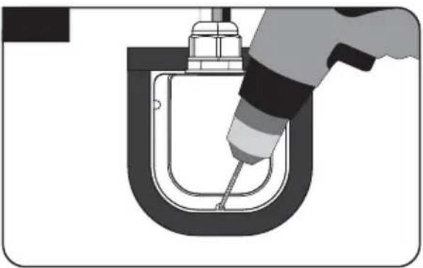
Place the assembled cable holder inside the tape marking and drill three(3) of 2 mm holes

natural_image
Technical diagram of a U-shaped mechanical component with a tool inserted, no visible text or symbols
Fix cable holder on the vehicle roof with three(3) of M4 x 20 screws on drill holes made
natural_image
Cross-sectional diagram of a mechanical component with a tool inserted, showing internal structure and no text or symbols.
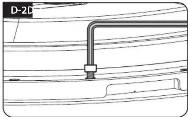
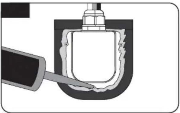
Apply silicone around cable holder and on the top of screws for waterproof
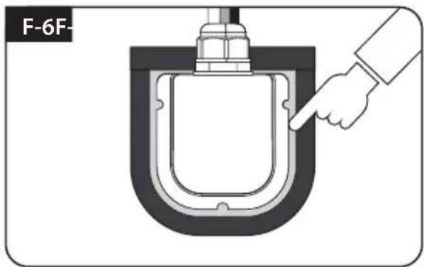
Connect cables to the ports of the antenna, remove masking tape and tidy silicone before dry
G. Controller installation
G-1
natural_image
Coiled cable with two connectors, no text or symbols visible
Get cigarette lighter adaptor (power input cable)
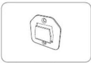
G-2
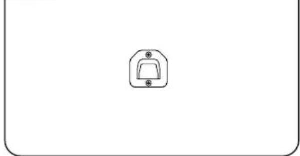
natural_image
Simple line drawing of a device handle with a circular button and two plus signs, enclosed in a rounded rectangle (no text or symbols)
Fix controller bracket where it should be fixed using two(2) of M4x16 screw

NOTE
The unit enables to have power from car battery. To make power input cable for direct connection, cut off cigarette lighter adaptor and peel off to take copper cables out.
natural_image
Technical line drawing of a mechanical component with no visible text or symbols
Connect power-controller-antenna using cigarette lighter adaptor and controller cable
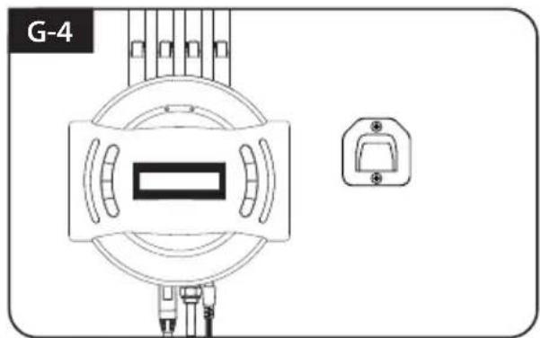
natural_image
Technical diagram of a mechanical component with a central rectangular component and a separate mounting bracket (no text or symbols)
Place controller on fixed bracket
Inhaltsverzeichnis
natural_image
Technical line drawing of a mechanical component or housing (no text or symbols)
natural_image
Simple line drawing of a rounded rectangular shape with small dots on its surface (no text or symbols)


natural_image
Coiled cable or hose with connectors, no visible text or symbols
SAT>IP WLAN-Kabel

natural_image
Coiled black cable with a metallic connector (no text or symbols visible)
natural_image
Coiled cable or wire with two connectors, no text or symbols visible
natural_image
Diagram showing a circular component with internal structure and three vertical rod-like structures aligned vertically (no text or symbols)
Controller / WLAN-Antennen (4)
natural_image
Simple line drawing of a switch or bracket component (no text or symbols)
natural_image
Coiled black cable or hose with two connectors, no text or symbols visible
Controllerkable - 12m, Schwarze

natural_image
Simple diagram with four empty rounded rectangles inside a rounded rectangle (no text or symbols)
Basispolster

natural_image
Line drawing of a briefcase with handle and ventilation slots (no text or symbols)


natural_image
Technical line drawing of a mechanical bearing housing (no text or symbols)

Kabelverschraubung Transportkoffer Kabe
natural_image
Simple L-shaped line drawing with no text or symbols
Inbusschlüssel

natural_image
Illustration of multiple screw fasteners arranged in rows (no text or symbols)
M6 × 15(8),
M4 × 16(2), M4 × 20(10)

Bedienungsanleitung

natural_image
Illustration of a medical or laboratory device with clamps and a rectangular device (no text or symbols)
Strom adapter (Optional)
natural_image
Hand pointing at a grid-patterned surface with a small symbol (no readable text or numbers)
Mobiler Einsatz

natural_image
Illustration of a hand pressing down on a rectangular object with sparkles (no text or symbols)
natural_image
Simple geometric shape with a rounded corner and scattered dots inside, no text or symbols present.
natural_image
Simple geometric shape with rounded corners and scattered dots, no text or symbols present.
natural_image
Abstract diagram of nested wavy lines within a rounded rectangular boundary (no text or symbols)
natural_image
Illustration of a tool injecting particles into a rounded rectangular container (no text or symbols)
natural_image
Diagram showing a dropper tip interacting with a rectangular object, labeled B-2 (no text or symbols on the diagram itself)
natural_image
Illustration of a pipette dispensing liquid into a rectangular container (no text or symbols)
natural_image
Diagram showing a dropper tip interacting with a rectangular object, labeled B-4 (no text or symbols on the diagram itself)
natural_image
Diagram showing a dropper injecting into a container with scattered particles (no text or symbols)
natural_image
Illustration of a hand pointing at a rectangular object with circular holes, labeled C-2 (no text or symbols on the object itself)
natural_image
Illustration of a hand holding a tool interacting with a circular object, labeled C-3 (no text or symbols on the object itself)
natural_image
Simple diagram of a rounded rectangular shape with scattered circular dots, labeled C-4 (no text or symbols within the shape)
natural_image
Pure diagram of a mechanical component with a bent pipe and six evenly spaced pins (no text or symbols)
natural_image
Technical line drawing of a mechanical component with no visible text or symbols
natural_image
Technical line drawing of a mechanical component with labeled section E-1 and D (no text or symbols beyond labels)
natural_image
Diagram of a U-shaped tool inserted into a container, labeled E-2 (no text or symbols on the diagram itself)
natural_image
Diagram of a U-shaped tube with two probes inserted into it, no text or symbols present
natural_image
Illustration of five different types of cable and connector packages, including coiled and wire-like components (no text or symbols)
natural_image
Technical line drawing of a mechanical or electrical connector assembly (no text or symbols)
natural_image
Illustration of a hand using a tool to lift a U-shaped pipe (no text or symbols)
natural_image
Pure technical diagram of a U-shaped pipe fitting with a tool inserted, no text or symbols present
natural_image
Cross-sectional diagram of a mechanical component with a tool inserted, showing internal structure without any text or symbols.
natural_image
Diagram of a hand pointing to a U-shaped mechanical component (no text or symbols)
G. Controller installation
G-1
natural_image
Coiled black cable with two connectors, no visible text or symbols
natural_image
Pure technical diagram of a mechanical or electrical component with no visible text, numbers, or symbols.
natural_image
Technical line drawing of a mechanical component with no visible text or symbols
natural_image
Technical line drawing of a mechanical component or housing (no text or symbols)
Unité principale
natural_image
Simple line drawing of a rounded rectangular shape with small dots on its surface (no text or symbols)
Plaque de fixation
natural_image
Coiled cable or hose with connectors, no visible text or symbols
Câble du SAT>IP LAN
natural_image
Simple line drawing of a cord with a string, no text or symbols present
natural_image
Coiled cable or hose with two connectors, no text or symbols visible
natural_image
Technical diagram showing a circular component with internal structure and three vertical rod-like components aligned vertically (no text or symbols)
natural_image
Simple line drawing of a switch or bracket component (no text or symbols)
natural_image
Coiled black cable or hose with two connectors, no text or symbols visible
natural_image
Simple diagram with four empty rounded rectangles arranged in a 2x2 grid inside a rounded rectangle (no text or symbols)
Coussin de la Base
natural_image
Line drawing of a briefcase with handle and ventilation slots (no text or symbols)
Mallette de transport
natural_image
Technical line drawing of a mechanical housing component (no text or symbols)
Support de câble
natural_image
Simple line drawing of a mechanical connector or fitting (no text or symbols)
Presse-étoupe
natural_image
Simple 3D L-shaped pipe or bent segment diagram without any text or symbols
clé Allen
natural_image
Illustration of multiple screw fasteners arranged in rows (no text or symbols)
M6 × 15(8),
M4 × 16(2), M4 × 20(10)
natural_image
Simple line drawing of a blank rectangular shape with rounded corners (no text or symbols)
natural_image
Illustration of a medical or laboratory device with coiled wires and a rectangular component (no text or symbols)
natural_image
Hand interacting with a digital grid interface (no visible text or symbols)

8-2. Spécifications
a. Antenne
natural_image
Illustration of a hand pressing down on a button with sparkles, labeled A-1 (no text or symbols on the button itself)
natural_image
Simple diagram of an oval shape with evenly spaced dots, labeled A-3 (no text or symbols within the shape)
natural_image
Diagram of a biological structure with wavy internal lines, labeled A-4 (no text or symbols within the diagram itself)
natural_image
Illustration of a pipette dispensing particles into a rectangular container (no text or symbols)
natural_image
Diagram showing a dropper tip interacting with a rectangular object, labeled B-2 (no text or symbols on the diagram itself)
natural_image
Illustration of a pipette dispensing liquid into a rectangular container (no text or symbols)
natural_image
Diagram showing a dropper tip interacting with a rectangular object, labeled B-4 (no text or symbols on the diagram itself)
natural_image
Diagram showing a dropper injecting into a rectangular container with scattered particles (no text or symbols)
natural_image
Illustration of a hand pointing at a rectangular object with circular holes, labeled C-2 (no text or symbols on the object itself)
surface de silicone Tidy
natural_image
Illustration of a hand holding a tool interacting with a circular object, labeled C-3 (no text or symbols on the object itself)
natural_image
Simple diagram of a rounded rectangular shape with scattered circular dots, labeled C-4 (no text or symbols within the shape)
natural_image
Pure diagram of a pipe with a series of small pins, no text or symbols present
natural_image
Technical line drawing of a mechanical component with no visible text or symbols
E. Câble installation de support 1

natural_image
Technical line drawing of a mechanical component with front and top views (no text or symbols)
natural_image
Diagram of a U-shaped tool inserted into a container, labeled E-2 (no text or symbols on the diagram itself)
natural_image
Diagram of a U-shaped tube with two probes inserted, showing liquid level (no text or symbols)
F. Câble installation du support 2
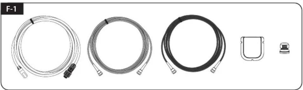
F-1
natural_image
Illustration of five different types of cable and connector packages, including coiled and wire-like components (no text or symbols)
natural_image
Technical line drawing of a mechanical or electrical connector assembly (no text or symbols)
natural_image
Illustration of a hand using a tool to lift a U-shaped pipe (no text or symbols)
natural_image
Technical diagram of a U-shaped mechanical component with a tool inserted, no visible text or symbols
natural_image
Cross-sectional diagram of a mechanical component with a tool inserted, showing internal structure without any text or symbols.
natural_image
Coiled black cable with two connectors, no visible text or symbols
natural_image
Technical line drawing of a mechanical component with no visible text or symbols
natural_image
Technical line drawing of a mechanical component with no visible text or symbols
natural_image
Technical line drawing of a mechanical component or housing (no text or symbols)
Hoofdunit

natural_image
Simple line drawing of a rounded rectangular shape with small dots on its surface (no text or symbols)
Montageplaat
natural_image
Coiled cable or hose with two connectors, no visible text or symbols
SAT>IP LAN-kabel

natural_image
Simple line drawing of a cord with a string, no text or symbols present
natural_image
Coiled cable or hose with two connectors, no text or symbols visible
natural_image
Technical diagram showing a circular component with internal structure and three vertical rod-like components aligned vertically (no text or symbols)
Bediening
natural_image
Simple line drawing of a switch or socket component (no text or symbols)
natural_image
Coiled black cable or hose with two connectors, no text or symbols visible
Bedieningkabel (12 m - zwart)
natural_image
Simple diagram with four empty rounded rectangles arranged in a 2x2 grid inside a rounded rectangle (no text or symbols)
natural_image
Line drawing of a briefcase with handle and ventilation slots (no text or symbols)
Draagtas
natural_image
Technical line drawing of a mechanical housing component (no text or symbols)
kabelhouder

natural_image
Simple line drawing of a mechanical connector or fitting (no text or symbols)
Kabelwartel

natural_image
Simple 3D L-shaped pipe or bent segment diagram without any text or symbols
Inbussleutel
natural_image
Illustration of multiple screw fasteners arranged in rows (no text or symbols)
M6 × 15(8),
M4 × 16(2), M4 × 20(10)
natural_image
Simple line drawing of a blank rectangular box with no text or symbols
natural_image
Illustration of a medical or laboratory device with coiled wires and a rectangular component (no text or symbols)
natural_image
Hand interacting with a grid-patterned surface (no visible text or symbols)
portable gebruik
Ga naar "Instellingen" ▷ "Wi-Fi" ▷ Selecteer "SATIPLINK2G" of "SATIPLINK5G"
Let op

8-2. Specifications
a. Antenne
natural_image
Illustration of a hand pressing down on a button with sparkles, labeled A-1 (no text or symbols on the button itself)
natural_image
Simple diagram of an oval shape with evenly spaced dots, labeled A-3 (no text or symbols within the shape)
natural_image
Diagram of a coiled structure labeled A-4, showing three parallel wavy lines inside a rounded rectangular frame (no text or symbols beyond label)
natural_image
Illustration of a pipette dispensing particles into a rectangular container (no text or symbols)
natural_image
Diagram showing a dropper tip interacting with a rectangular object, labeled B-2 (no text or symbols on the diagram itself)
natural_image
Illustration of a pipette dispensing liquid into a rectangular container (no text or symbols)
natural_image
Diagram showing a dropper tip interacting with a rectangular object, labeled B-4 (no text or symbols on the diagram itself)
C. Breng siliconen tussen fix beugel en Afplakband
natural_image
Diagram showing a dropper injecting into a rectangular container with scattered particles (no text or symbols)
natural_image
Illustration of a hand pointing at a rectangular object with circular holes, labeled C-2 (no text or symbols on the object itself)
Tidy siliconenoppervlak
natural_image
Illustration of a hand holding a tool interacting with a circular object, labeled C-3 (no text or symbols on the object itself)
natural_image
Simple diagram of a rounded rectangular shape with scattered circular holes, labeled C-4 (no text or symbols within the shape)
natural_image
Pure diagram of a mechanical component with a bent pipe and seven evenly spaced pins (no text or symbols)
natural_image
Technical line drawing of a mechanical component with no visible text or symbols
natural_image
Technical diagram showing a mechanical component with labeled section E-1 and a D-shaped outline (no text or symbols beyond labels)
natural_image
Diagram of a mechanical component with a U-shaped groove and a threaded rod inserted into a container (no text or symbols)
natural_image
Diagram of a U-shaped tube with two probes inserted into it, no text or symbols present
natural_image
Illustration of five different types of cable and connector packages, including coiled and wire-like components (no text or symbols)
SAT> IP LAN-kabel, Bedieningkabel, Ontvangerkabel, kabel houder en Kabelwartel nodig
F-2
natural_image
Technical line drawing of a mechanical or electrical connector assembly (no text or symbols)
natural_image
Illustration of a hand using a tool to lift a U-shaped pipe (no text or symbols)
natural_image
Technical diagram of a mechanical component with a tool inserted, no visible text or symbols
natural_image
Cross-sectional diagram of a mechanical component with a tool inserted, showing internal structure without any text or symbols.
natural_image
Coiled cable with two connectors, no text or symbols visible
natural_image
Simple line drawing of a device handle with a circular button and two plus signs (no text or symbols)
natural_image
Technical line drawing of a mechanical component with no visible text or symbols
natural_image
Technical diagram of a mechanical component with a central rectangular block and a separate mounting bracket (no text or symbols)