Snipe Platinum - Receiver Selfsat - Free user manual and instructions
Find the device manual for free Snipe Platinum Selfsat in PDF.

| Product Type | Satellite receiver with motorized flat antenna |
| Brand | Selfsat |
| Model | Snipe Platinum |
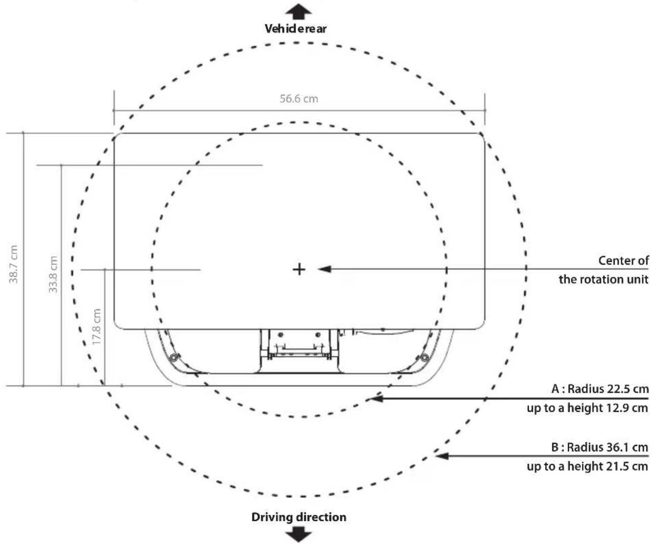
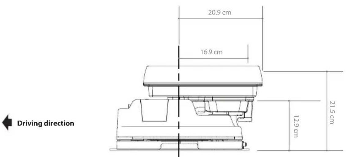
| Antenna dimensions (L x D x H) | 566 x 367 x 212 mm |
| Antenna weight | 11.6 kg |
| Remote control (L x D x H) | 140 x 50 x 18 mm |
| Remote control weight | 23 g |
| Power supply | DC 12 V (via cigarette lighter or battery) |
| Power consumption | 30 W while moving |
| Input frequency | 10.7 ~ 12.75 GHz |
| Antenna gain | 34.5 dBi @ 12.7 GHz |
| Polarization | Horizontal / Vertical |
| Elevation angle | 15° ~ 90° |
| Azimuth angle | 360° |
| Skew angle | -40° ~ +40° |
| Satellite switching system | DiSEqC 1.1 |
| Satellite acquisition time | 180 seconds (average) |
| LNB output frequency | 950 ~ 2,150 MHz |
| Local oscillator frequency | 9.75 / 10.6 GHz |
| Number of LNB outputs | 1 or 2 (optional) |
| Connectivity | Bluetooth 4.2, 2.4 GHz remote control |
| Main features | Automatic alignment to preset satellite, satellite search, HOME position, standby mode, SAT CONNECT mobile app |
| Maintenance and cleaning | No regular maintenance required; avoid automatic car wash and high-pressure cleaner |
| Safety | Installation only on a solid roof; comply with laws and regulations; cut power to the STB before turning off the antenna |
| Spare parts and repairability | Included accessories: mounting plate, PI box, cables, remote control, bracket, key; repair only at authorized center |
Frequently Asked Questions - Snipe Platinum Selfsat
User questions about Snipe Platinum Selfsat
0 question about this device. Answer the ones you know or ask your own.
Ask a new question about this device
Download the instructions for your Receiver in PDF format for free! Find your manual Snipe Platinum - Selfsat and take your electronic device back in hand. On this page are published all the documents necessary for the use of your device. Snipe Platinum by Selfsat.
USER MANUAL Snipe Platinum Selfsat
2-1. Accessory included 4
2-2.Name of parts 5
3. Operating Instruction
3-1. Connection diagram 6
3-2. Functional description 7
3-3. Quick reference 13
4.Software Update 13
5.Troubleshooting 14
6. Specifications
6-1. Dimension 15
6-2. Specifications 16
7. Caravan/Motorhome Installation
7-1. Required space for installation 17
7-2. Equipment for installation 18
7-3. Instruction for installation 18
1. General Information
1-1. Introduction
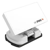
SNIPE PLATINUM is an intelligent satellite-TV reception system which can align itself towards a preset satellite automatically as long as the system is located within the footprint of the selected satellite.
SNIPE PLATINUM applies a new flat antenna with better reception than the regular SNIPE series for better performance(antenna gain 34.5dBi), but still takes up only occupies requisite space while it performs the necessary adjustments with slim and agile antenna body.
These instructions describe the functions and operation of SNIPELATINUM, auto skew satellite system with Remote control function.
Correct and safe operation of the system can only be ensured by following instruction, both for installation and operation.
For general operation, please ensure that the system always has a clear view to the sky. In Europe, all satellites are in an approximate position on the equator. If the satellite's signal beam is interrupted by obstacles such as mountains, buildings or trees, the unit will not function and no TV signal will be received.
For more information on general use of this unit consult local dealer for assistance.
1-2. Proper use and operation
This product has been designed for portable use or fixed installation on vehicles with maximum speeds of 130km / h . The unit is programmed to automatically aims at geostationary television satellites.
The power is supplied by a standard vehicle electrical system with a rated voltage of 12VDC. For installations on the vehicle, use power input cable (cigarette lighter cable) to supply power.
For portable use, optional power adaptor produced by manufacturer must be used.
Please also note the following instructions from the manufacturer :
It is not possible to add or remove components on this product.
- The use of other components other than those originally supplied is not permitted.
- To complete installation, installer must strictly follow instruction in the supplied user manual. Failure to follow the user manual may cause damage to the unit or user's vehicle.
- The product does not require any regular maintenance; all service must be carried out at approved service centers.
- All relevant guidelines of the automotive industry must be observed and complied with.
- The equipment must only be installed on solid vehicle roofs.
- Avoid cleaning user's vehicle with the mounted satellite system in a drive-through car wash or a car wash with a high-pressure cleaner.
1-3. Safety notes
Please carefully read and follow the operating instructions in this manual and use the SNIPE PLATINUM for its intended purpose.
Upon installation of SNIPELATINUM, please ensure the installation is done with supplied cables and ensure the cables are not modified in any way.
As the user of this equipment, be responsible for ensuring compliance with the relevant laws and regulations.
The manufacturer does not take liability for direct or indirect consequential damage of the system, motor vehicles or other equipment by reason of unsuitable battery usage or erroneous installation or wrong wire connection.
2. Contents
2-1. Accessory included
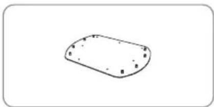
Main unit Mounting plate
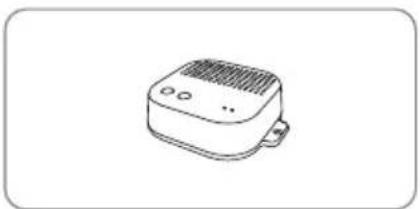
PI box
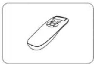
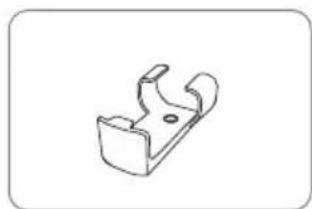
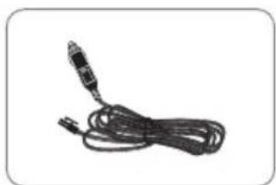
Remote control bracketRemote cogirette lighter adaptor
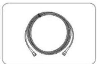
Signal cable - 12 m (x2 for twin outputs)
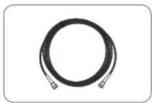
PI cable - 1.5m
Base pads
Cable glandCable holder
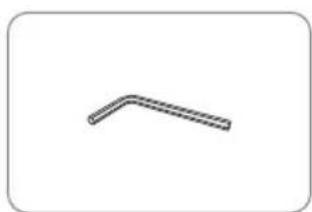
Allen wrench
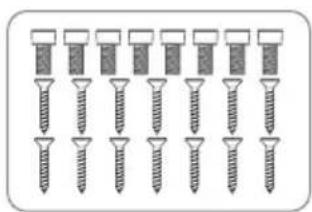
M6 × 15(8), M4 × 20(14)
User manual
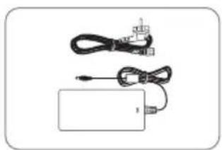
Power adaptor (Optional)
Actual components may differ from the above images.
The unit enables to have power from car battery. To make power input cable for direct connection, cut off cigarette lighter adaptor and peel off to take copper cables out.
※ Only power adaptor produced by SNIPE series manufacturer is guaranteed and has be used.
* Power adaptor has to be purchased separate. Please ask to local dealer/shop for more information.
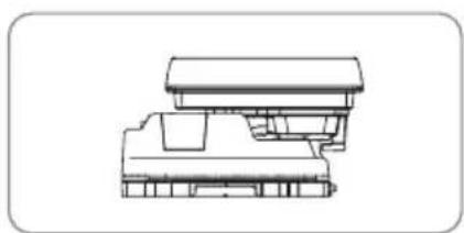
2-2. Name of parts
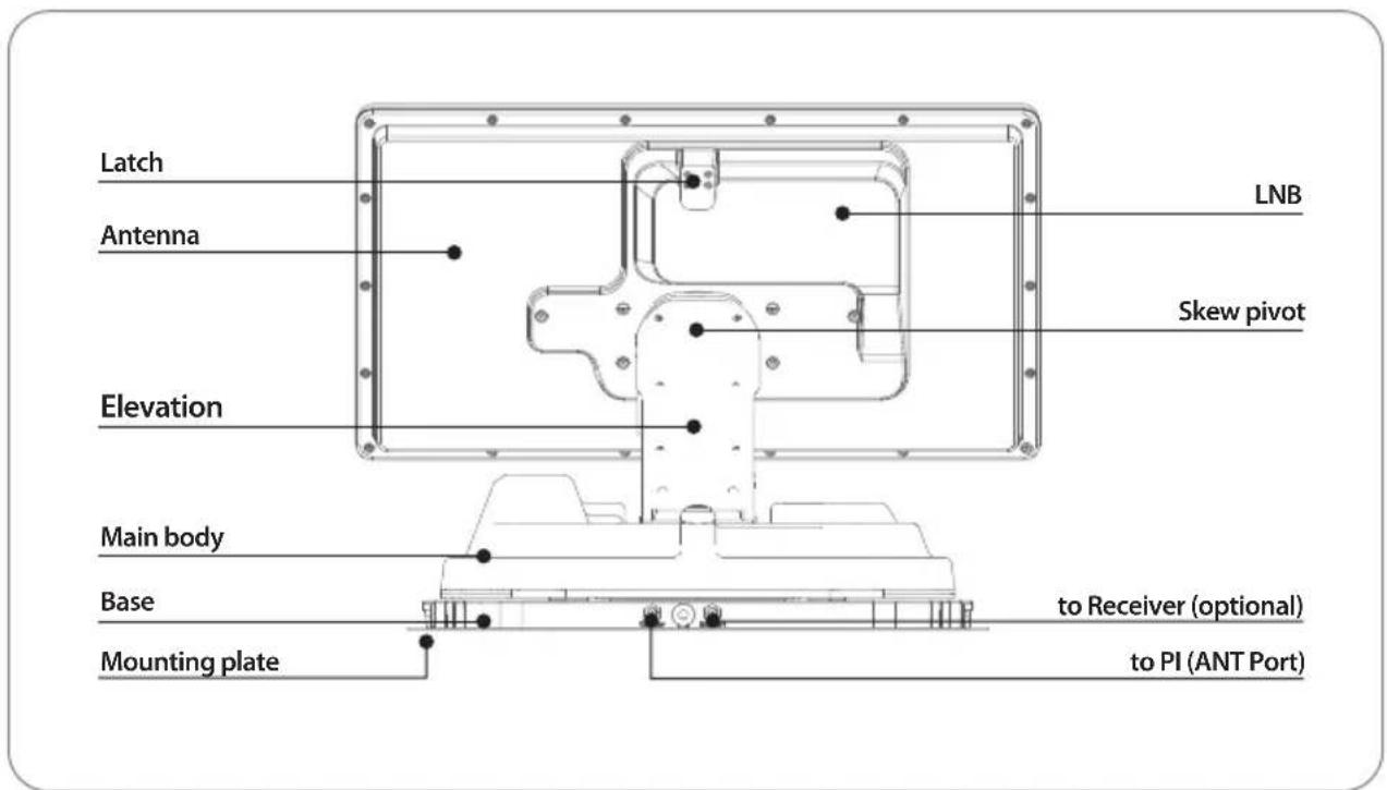
Main unit
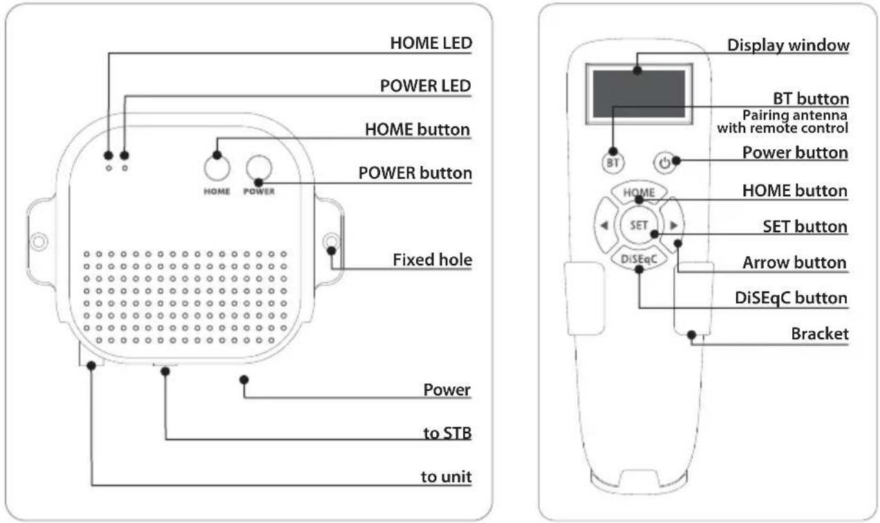
PI box Remote control
3. Operating Instruction
3-1. Connection diagram
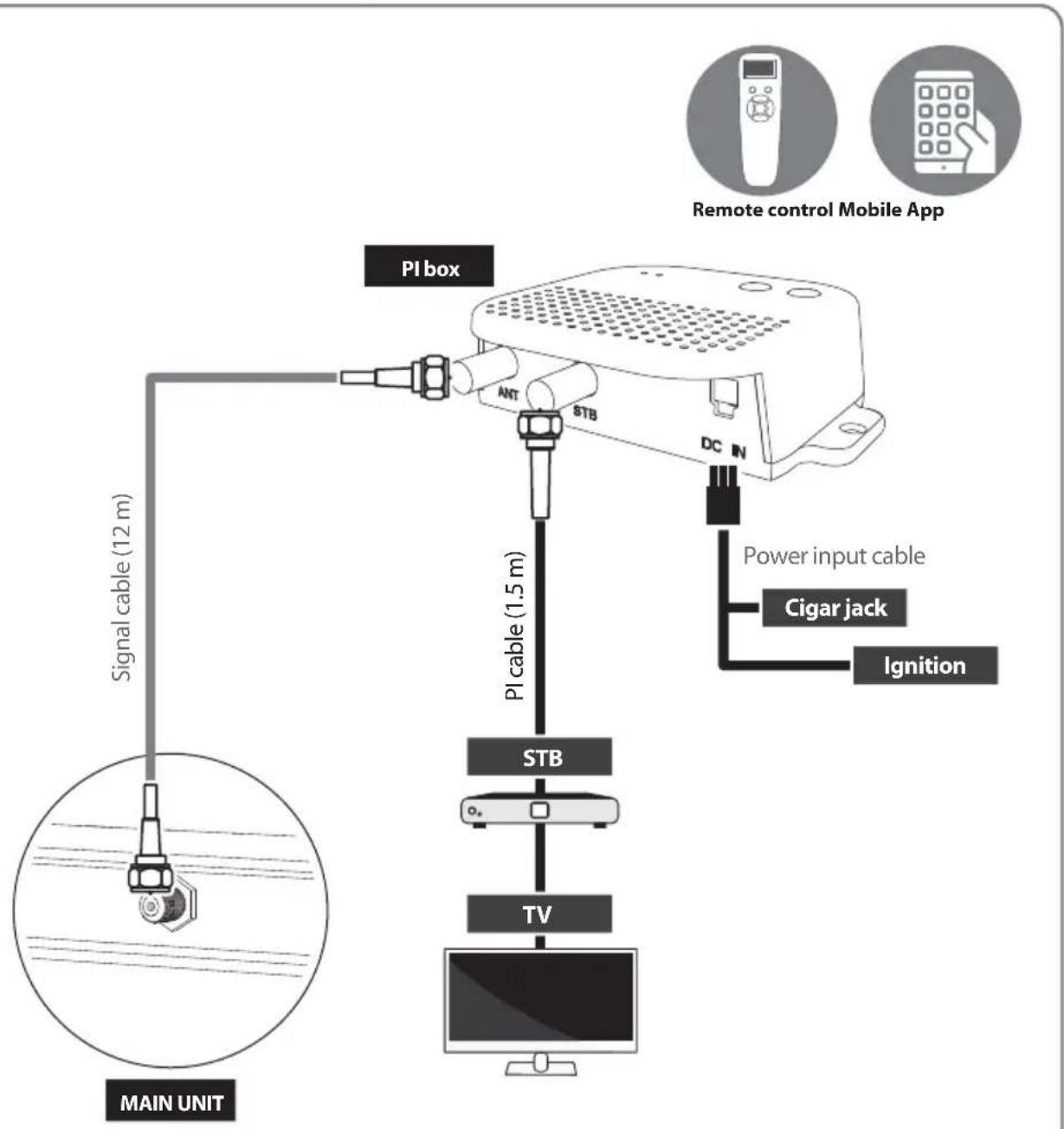
Turn on the PI power after all cables connections are complete. When not using the antenna, turn off the PI power.
Portable use
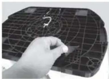
Attach four(4) base pads to the bottom of antenna base.
3-2. Functional description
1. PI box
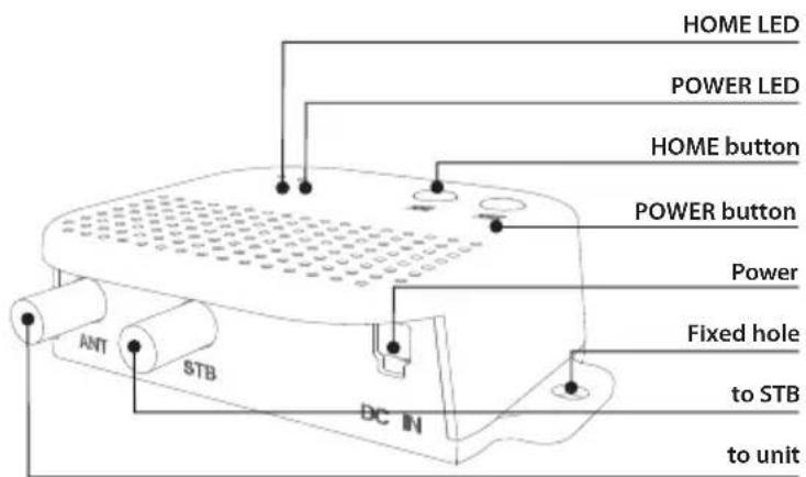
A. HOME Button / HOME LED (Blue)
i. When the Home button is pressed, the antenna moves to the home position
ii. HOME LED turn on when the antenna is in the home position, and Blink when the antenna is move to home from another position
B. POWER Button / POWER LED (Red)
a. Press the POWER button to turn on the PI box, and power to the antenna unit
ii. POWER OFF / LED OFF
a. n order to turn off the PI power, you must first turn off the STB power
b. When the power of the STB is turned off, Press and hold for more than 3 seconds to turn off the power. (Power LED OFF)
- At this time, if the antenna is not in the home position (e.g. when towards the satellite), the power is turned off after the antenna is moved to the home position
c. If the STB is not powered off, the PI BOX does not turn off even when the power button is pressed, and the POWER LED flashes to indicate that the STB Power is ON.
- At this time, the PI does not turn off, and only the antenna moves to the home position
C. Basic Features
i. Power save mode
a. When receiving a broadcast signal or when the antenna is in the home position, the antenna operates only with the current from the STB
b. When searching for a satellite or when the antenna moves, it automatically changes to the power connected to DC power adapter
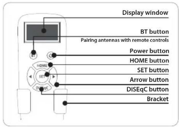
2. Remote control
A. Sleep mode - battery save mode
i. When not used for more than 15 seconds, it enters the power saving mode. (When the battery is inserted in the remote control)
ii. To return from sleep mode, press only SET button
B. BT Setting
i.BT button
a. Press BT button to change to BT setting screen. Press the arrow to move to the desired function and set with the SET button
b. Press and hold BT button for more than 5 seconds to reset the remote control

When use antenna and remote control for the first time or when you delete the antenna list stored in the remote control, a list of products that can be connected will appear.
Press the left and right buttons on the remote control to select the MAC Address of your antenna unit, and press the SET button to connect to the remote control
SNIPE PLATINUM has two MAC addresses, so need to choose exactly according to the use

MAC address of PI BOX of SNIPELATINUM When use antenna and remote control for the first time, must select a MAC address starting with WP

MAC address starting with WM used for special operations and should not be selected in general situations.
For details, refer to [G. Additional function].

When using general operations, it is displayed abbreviated on the remote control screen

Delete the MAC Address of antenna stored in the remote control. Used to connect to other products
C. Power Button
i. POWER ON
a. When press the POWER button on the remote control, the PI turns on and the antenna is powered on
W-E9:FC
Press POWER
Indicated when PI is off. When you press the power button, the screen changes as shown below
W-E9:FC
PI POWER ON
Indicated when PI is turn on (appears for about 2 seconds)
ii. POWER OFF
a. Press the power button of Remote control and hold for more than 3 seconds to turn off the PI power after the antenna is moved to the home position
b. In order to turn off the PI power, you must first turn off the STB power. Can be checked the states of STB power on the remote control screen
W-E9:FC
Press POWER
Indicated when PI power (antenna power) is turn off
W-E9:FC
Now STB On
Home
Indicated that the PI cannot be turned off because the STB power is on (appears for about 1 second)
c. When the power of the STB is turned off, press the power button of Remote control, the power of PI is turned off after the antenna is moved to the home position (if the antenna is not in the home position)
d. If the STB's power is not turned off, the PI BOX will not turn off even if you press the power button on the remote control, and the remote control screen indicates that the STB power is ON. At this time, the PI does not turn off, and only the antenna moves to the home position
D. Basic Features
CONNECTING
Remote control
Version:XX
W-E9:FC
Connected
The remote control automatically searches for nearby antenna unit.
If there is an antenna that has been connected before, connect it immediately
When the remote control and the antenna are connected, a "Connected" message appears.
| W-E9:FC |
| ASTRA 1 |
| Home |
The MAC Address of the connected antenna, the satellite name set for the antenna, and the current status are displayed.
Press the left or right arrow button to select the desired satellite and press the SET button to search for the satellite
HOME - When the antenna is in the home position Searching - When the antenna is searching for satellites Found SAT - When the satellite search is complete Mov To Home - the antenna will move to the home pos
E. DiSEqC setting
| W-E9:FC D |
| ASTRA 1 |
| Found SAT |
Pressing the DiSEqC button changes the DiSEqC settings of antenna unit. DiSEqC mode is indicated by [D] mark in the first line
The DiSEqC function is disabled when the antenna is in the HOME position. To use DiSEqC, press the DiSEqC button to activate the function when the message 'Searching' or 'Found SAT' to appear on the remote control screen
When the user sets up the STB to use DiSEqC 1.1, the list of DiSEqC satellites in the STB must be set in the same order as the list of satellites in SNIPE
Refer SNIPE's pre-satellites for DiSEqC 1.1 below.
If an error occurs during operation, the error code appears with the error statement.
Error ELdn - EL Movement
Error COM - Communication error
If an error message appears, turn off the power of the STB and PI, disconnect all connected cables, and reconnect them
G. Additional function
SELECT MAC
WM-E9:FC:E4
PRESS SET
MAC addresses starting with WM are used for special operations, When pairing to the product using this MAC address, other functions cannot be used (such as satellite search).
Do not select in normal operations, other than emergency mode or firmware update mode
Emergency mode
If the antenna is stopped in an abnormal state with 'ERROR Com' displayed on the remote control (or the PI was brokendown), the antenna can be returned to its home position through the following process
- Instead of PI, connect another 24V power supply directly to the antenna. (Via coaxial cable)
- Pair by selecting a MAC address starting with WM- instead of a MAC address starting with WP with the app or remote control
- When you press the home button on the remote control, the antenna returns to the home position
3. Mobile application
A. Download the app from the App Store (Android/iOS)
Search for SELFSAT on the App Store and download "SAT CONNECT" app
※ Before using this app, need to activate BT and GPS function on your smart device.
B. Pairing the antenna with App
step 1. Check the MAC Address at your antenna unit (on the antenna or PI box / User manual)
step 2. When you run the downloaded application, a connectable antenna unit is automatically detected
step 3. Select the one that matches your antenna MAC Address
There are two antenna MAC addresses, one starting with WM- and one starting with WP.
For satellite search operation, must select a MAC address that starting with WP.
step 4. Click the 'connect' button to complete Bluetooth connection between your antenna unit and smart device
C. Basic Features
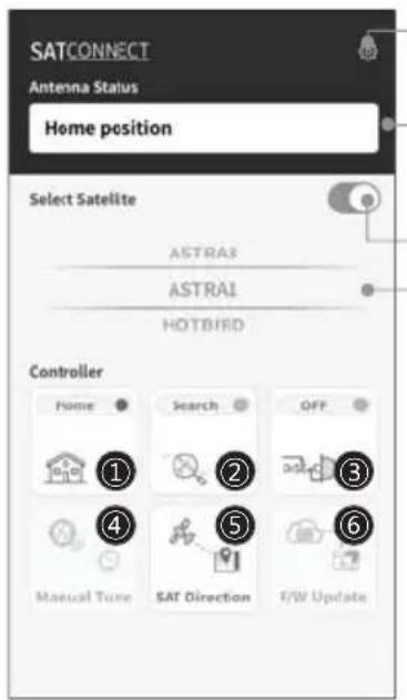
Setting button
Firmware version, language setting can be checked
Status display window
Indicates the current status of the antenna
Antenna power ON/OFF
To power off the antenna, you must first power off the STB.
Power off the STB, then press the power button to power off after the antenna moves to the home position.
If the power button is pressed while the receiver is not powered off, the antenna only moves to the home position and the power does not turn off
Satellite selection window
Select a satellite to search
① Used to move the antenna to the home position.
The orange lamp blinks while moving to the home, and the green lamp turns on after it has completely moved to the home position
② Used to searching satellites.
Select the desired satellite and press the button, the antenna will search for it. While searching for a satellite, the orange lamp flashes, and when a satellite is found, the green lamp lights up
③ Used to set DiSEqC support of set-top box.
When DiSEqC is set, the orange lamp turns on and supports DiSEqC in the set-top box
④ Used to move the antenna manually.
This option is only available after completing the satellite search.
This option allows to manually move the antenna, but it does not guarantee optimal performance.
(5) Used to check the direction of the selected satellite
(6) Used to update the firmware of the antenna.
To update the F/W, must select a MAC address starting with WM- instead of a MAC address starting with WP-.
"NEW" message appears when there is a new updated version of F/W
After completing the update, you need to unpair the antenna's WM-MAC address and re-pair with the WP-MAC address.
3-3. Quick reference
- Turn on the remote control and select the unit that matches the MAC Address(starting with WM-) of your antenna.
- Use the left and right arrow buttons to select the satellite and press the SET button.
- Wait for the message 'FOUND SAT' to appear on the remote control screen.
- When the satellite search is complete, watch the broadcast.

WARNING
When you physically move unit, the unit must be returned to HOME position to prevent damage.

NOTE
SNIPE PLATINUM will be automatically folded back to HOME position if vehicle moves faster than 30km / h when the unit is powered.
SNIPE PLATINUM supports the ignition function. If the ignition cable is connected, the antenna automatically moves to the home position when the vehicle starts.
4. Software Update
- Download and install the Sat Connect app from the App store
- Turn on the receiver power and PI BOX
SELECT MAC
WM-E9:FC:E4
PRESS SET
- Pair the app with the antenna. At this time, the antenna should select a MAC address starting with WM (instead of a MAC address starting with WP-)
- Select [F/W Update] from the menu to update the antenna
- After completing the update, must unpair the WM- MAC address of antenna and re-pairing with the WP- MAC address
5. Troubleshooting
There are a number of common issues that can affect the signal reception quality or the operation of the unit. The following sections address these issues and potential solutions.
A. No function when power on the antenna
i. Check again all the cable connections have been made correctly.
- Connection between the power and the PI box.
- Connection between the PI box and antenna.
ii. Check if the power input cable has been damaged.
iii. Check the battery polarities (+ / - )
iv. Check if the PI Box is powered on (Check Power LED of PI BOX is on)
B. The remote control does not turn on
i. Try pressing any button other than the DiSEqC button.
ii. Check if the battery is properly inserted.
iii. Check if the remote control's battery is exhausted.
C. Fail to search the selected satellite
i. Satellite signals can be blocked or degraded by buildings, trees. Make sure there are no obstructions in a southward direction.
ii. Select another satellite as example Astra3, if this locks then select your desired satellite. ie Astra1.
iii. Turn the unit off and then back on again and select desired satellite.
iv. Turn off the STB or TV with DVB-S2-Tuner and start the satellite search again. Only switch on the STB or TV with DVB-S2-Tuner, after your sat system has found the satellite.
D. Mechanical problems
i. If the antenna does not move into desired position.
- Try to power OFF/ON again.
ii. If the antenna makes a noise whilst remaining static.
- Try to power OFF/ON again. If problem persists, please contact local dealer/shop for assistance.
E. Other issues
i. If the system has been improperly wired, it will not operate properly. Contact local dealer/shop for assistance of cable damage.
6. Specifications
6-1. Dimension
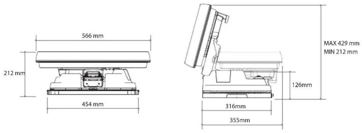
SNIPE PLATINUM
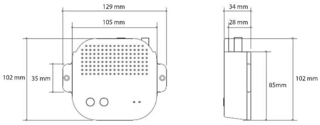
PI box
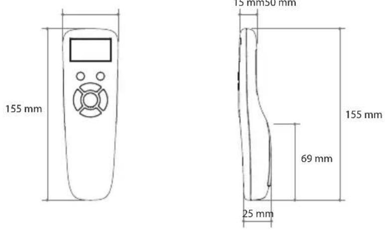
Remote control
6-2. Specifications
| Model | SNIPE PLATINUM | |
| Input Frequency | 10.7 ~ 12.75 GHz | |
| Polarization | Vertical & Horizontal | |
| Antenna Gain | 34.5 dBi @ 12.7 GHz | |
| Size (W x D x H) | (ANT) 566 X 367 X 212 mm | |
| Weight | (ANT) 11.6 kg / (RCU) 23 g | |
| Min EIRP | 48 dBW | |
| Angle Range (EL / AZ / SK) | 15° ~ 90° / 360° / -40° ~ +40° | |
| Satellite Switching System | DiSEqC | |
| Satellite Searching Time | 180 seconds (average) | |
| LNB | Output | 1 / 2 output (optional) |
| Output Frequency | 950 ~ 2,150 MHz | |
| L.O. Frequency | 9.75 / 10.6 GHz | |
| Input Voltage | DC 12 V | |
| Power Consumption | 30 W (in searching) | |
| Model | Remote control | |
| Frequency | 2.4 GHz | |
| Support Bluetooth version | Ver 4.2 | |
| BLE Gain | TX power | up to +3 dBm |
| RX sensitivity | down to -92 dBm | |
| Size (W x D x H) | 140 X 50 X 18 mm | |
| Screen size (L x H) | 128 X 64 Pixels | |
| Battery | AAA X 2 | |
7. Caravan/Motorhome Installation
7-1 . Required space for installation
Please allow that there is enough space around for flat antenna section to complete a full 360^ scan of the sky and return to the HOME position.
7-2. Equipment for installation
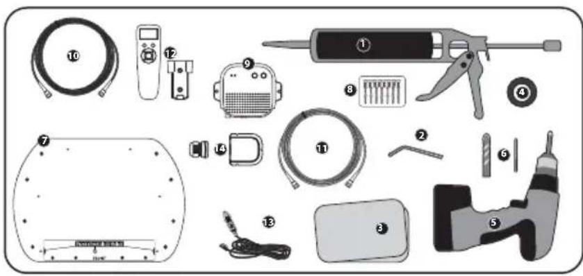
Silicone
2 Allen wrench
Cleaner
4 Masking tape
5 Power drill
6 2mm drill bit, over 20mm drill bit
7 Mounting plate
M6×15(8),M4×20(14)
9 PI box
10 PI cable (1.5m)
1 Signal cable (12m)
Remote conteol, Remote conteol bracket
Cigarette lighter adaptor (Power input cable)
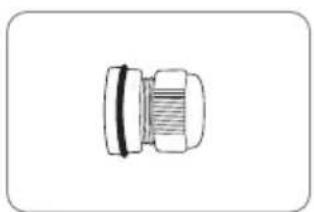
14 Cable holder & gland
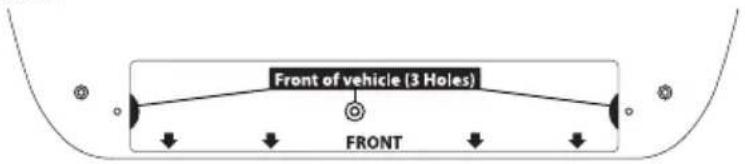
Mounting plate direction


ving direction


7-3. Instruction for installation
A. Mounting plate installation on a vehicle roof
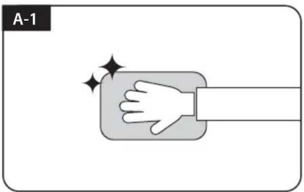
Clean the surface with cleaner
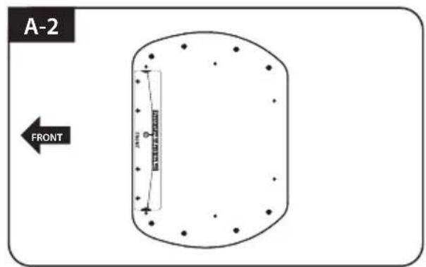
Locate mounting plate in the center of the vehicle roof
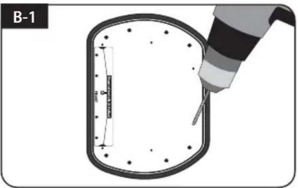
Attach masking tape outside of the mounting plate by 5mm away from the plate edges
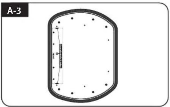
Put aside the mounting plate to apply silicone within the attached tape line but leave 2cm inward gap from the line
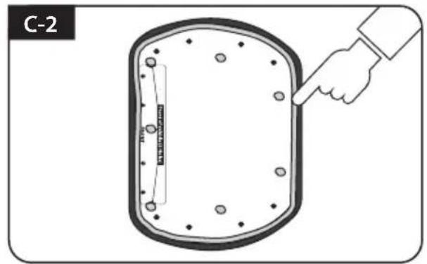
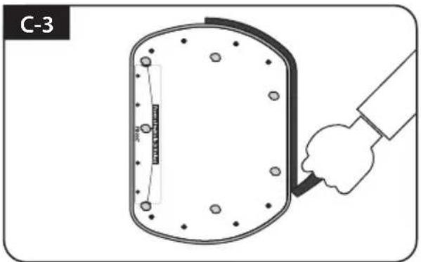
B. Assemble 7pcs of M4x20 bolt to fix the mounting plate
Place the mounting plate on the silicone and make 7 holes (2mm) with a power drill

Apply silicone on the holes
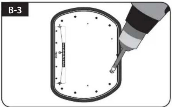
Assemble seven(7) of M4x20 screw Re-apply silicone to cover bolts assembled
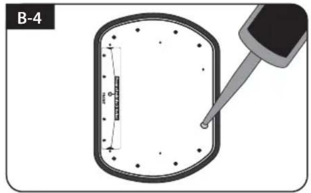
C. Apply silicone between mounting plate and masking tape
Apply silicone around mounting plate edges
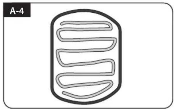
Tidy silicone surface
Remove masking tape and allow to dry
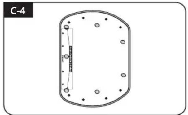
Prepare to place the antenna on to the upright bolts
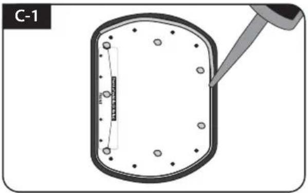
D. Fix mounting plate with 8 pcs of M6x15 bolt using allen wrench
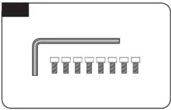
Parts required, allen wrench and eight(8) of M6×15 bolt
Place the antenna on mounting plate and tighten firmly each bolt by allen wrench
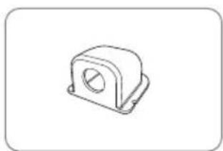
E. Cable holder installation 1
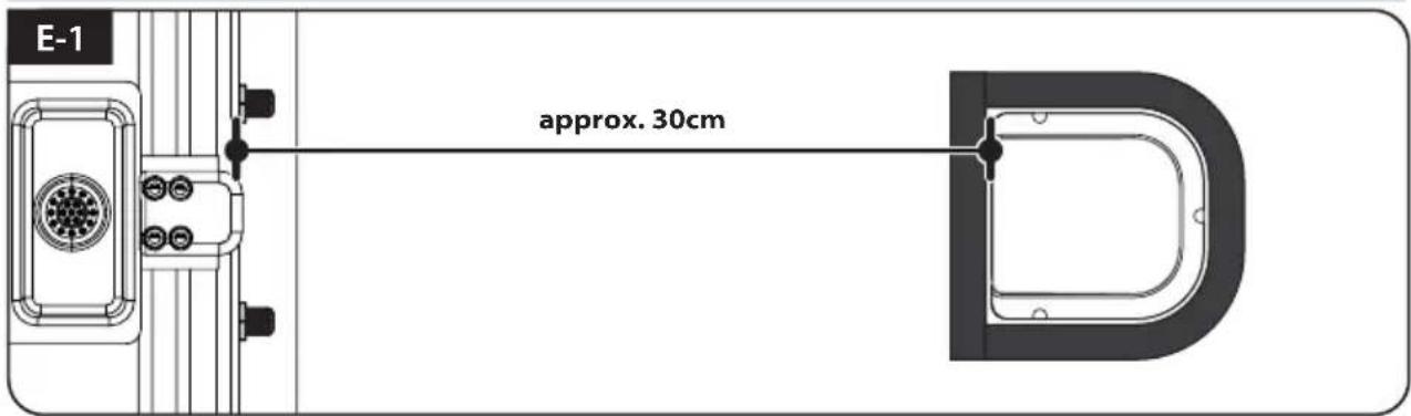
Place cable holder 30cm away from the rear center of the antenna. Apply masking tape 5mm from away the outside of holder
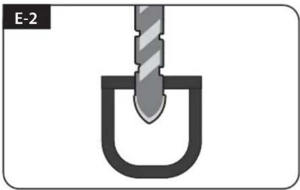
Drill a 20mm hole in the center of the tape marking
Make sure that hole size is minimum so that the cable can pass through
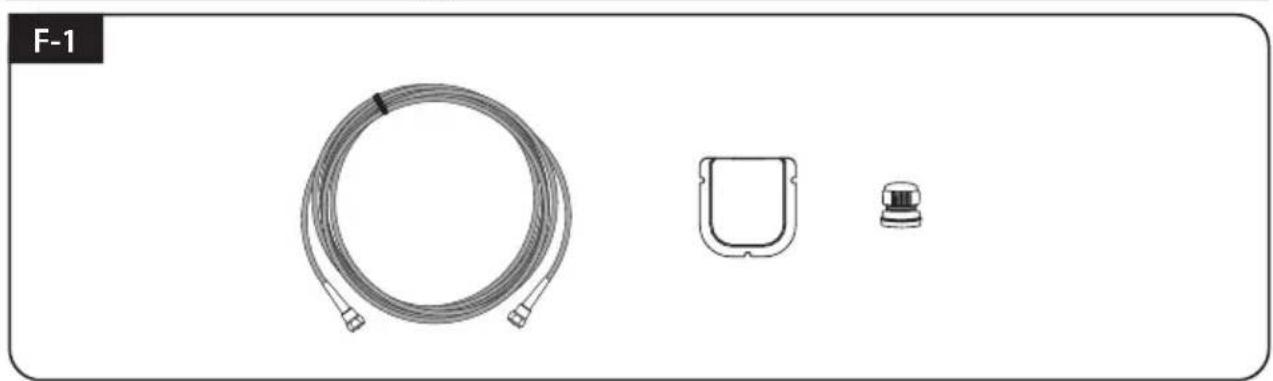
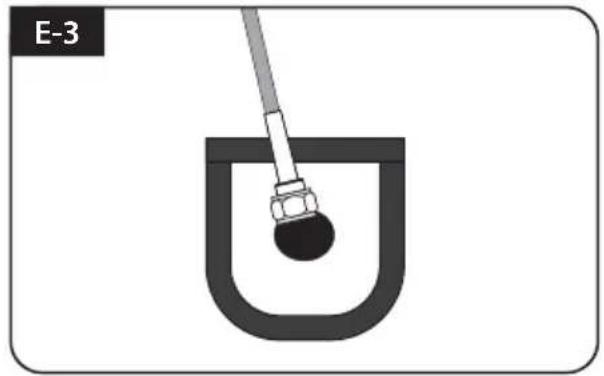
F. Cable holder installation 2

Signal cable, cable holder and gland are required
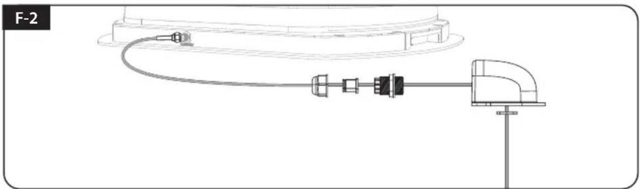
Set up required parts as above picture
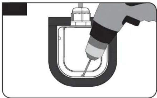
Place the assembled cable holder inside the tape marking and drill three(3) of 2mm holes
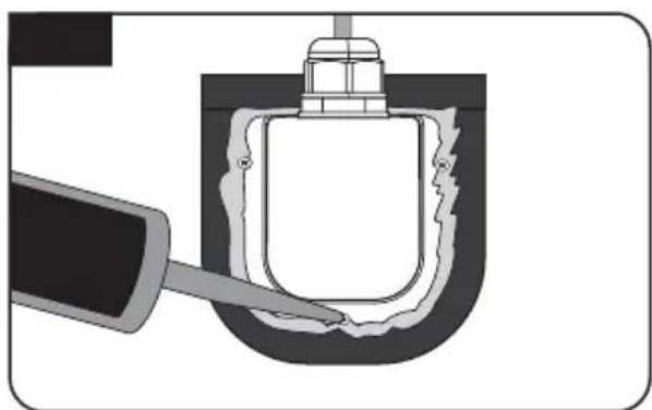
Apply silicone around cable holder and on the top of screws for waterproof
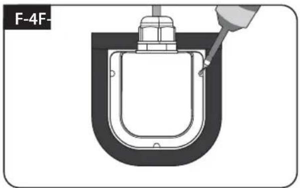
Fix cable holder on the vehicle roof with three(3) of M4 x 20 screws on drill holes made
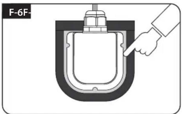
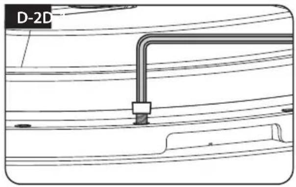
Connect cables to the ports of the antenna, remove masking tape and tidy silicone before dry
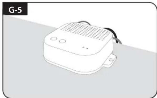
G. PI box and Remote control installation

Get Power input cable and plug into cigar lighter socket (12V outlet)
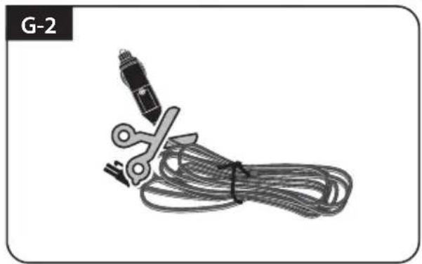
To source power from car battery, cut off cigar-jack connector to take inner three cables out and peel off each to take copper cable out
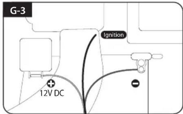
Match the power cables polarities to the battery polarities, red to red / black to black and white ignition cable to ignition port of the vehicle
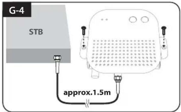
Fix PI Box where it should be fixed using two(2) of M4x20 screw
Connect power-PI box-receiver using cigarette lighter adaptor and PI cable
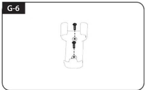
Fix Remote control bracket where it should be fixed using two(2) of M4x20 screw
Inhaltsverzeichnis
B. POWER-Taste / POWER-LED (Rot)
F. Cable installation du support 2