Snipe Dish 65 - Receiver Selfsat - Free user manual and instructions
Find the device manual for free Snipe Dish 65 Selfsat in PDF.

User questions about Snipe Dish 65 Selfsat
0 question about this device. Answer the ones you know or ask your own.
Ask a new question about this device
Download the instructions for your Receiver in PDF format for free! Find your manual Snipe Dish 65 - Selfsat and take your electronic device back in hand. On this page are published all the documents necessary for the use of your device. Snipe Dish 65 by Selfsat.
USER MANUAL Snipe Dish 65 Selfsat
2-1. Components bundle 4
2-2.Name of parts 5
3.How to assemble 6
4. Connection diagram 12
5. Skew adjustment 13
6. Functional description
6-1. Get ready to use 15
6-2. Searching the satellite 16
6-3. DiSEqC 1.1 setting 16
6-4. STB power detection On/Off 17
6-5. Power save mode 17
7. Extra functions
7-1.Error message 18
7-2. Factory reset 18
7-3. Software upgrade 18
7-4. Manual satellite update function 19
- Trouble shooting 20
9. Specifications
9-1. Dimension 21
9-2. Specifications 21
10. Caravan/Motorhome installation
10-1. Required space for the SNIPE DISH 22
10-2. Equipment for installation 24
10-3. Instruction for installation 24
1. General Information
1-1. Introduction
These instructions describe the functions and operation of the SNIPE DISH satellite system.
Correct and safe operation of the system can only be ensured by following these instructions.
Your SNIPE DISH is an intelligent satellite TV reception antenna system which can align itself towards a preset satellite automatically as long as the system is located within the footprint of the selected satellite.
For general operation, please ensure that the system always has a clear view to the sky. If the satellite's signal beam is interrupted by obstacles such as mountains, buildings or trees, the unit will not function and no TV signal will be received.
1-2. Proper use and operation
This product has been designed for fixed installation on vehicles with maximum speeds of 130km / h . It is designed to automatically aim an antenna at geostationary television satellites. The power to the system is supplied by a standard vehicle electrical system with a rated voltage of 12 Volts DC.
Use of the equipment for any other purpose to the one specified is not permitted.
Please also note the following instructions from the manufacturer :
- It is not permitted to change the overall device by removing or adding individual components. The use of any other parabolic reflectors or LNBs to those originally installed is not allowed.
- Installation must only be performed by sufficiently qualified personnel. All instructions in the supplied Installation instructions, which is separately provided, must be carefully followed.
- The product does not require any regular maintenance. Housings and enclosures must not be opened. Check and maintenance work should always be carried out by a qualified specialist.
- All of the relevant and approved guidelines of the automotive industry must be observed and complied with.
- The equipment must only be installed on hard vehicle roofs.
- Avoid cleaning your vehicle with the mounted satellite system in a single-bay or drive-through car wash or with a high-pressure cleaner.
- In case of storm or strong winds, bring the antenna down.
1-3. Safety notes
In order to ensure that your SNIPE DISH works properly you must ensure that it is following by the Operating Instructions in this manual and used as intended purpose.
When it is correctly installed, the antenna automatically assumes the rest position when the ignition is switched on and locks itself.
The driver of the vehicle must inspect the antenna unit before driving off to ensure that the antenna is properly stored in safe. Check with your naked eye to see if the antenna is fully folded.
As the user of this equipment, you are responsible for yourself ensuring compliance with the relevant laws and regulations.
The manufacturer does not take liability for direct or indirect consequential damage of the system, motor vehicles or other equipment by reason of unsuitable battery usage or erroneous installation or wrong wire connection.
2. Contents
2-1. Components bundle
Main unit
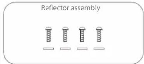
Truss head M6 × 15 (4), M6 Flat mold washer (4)
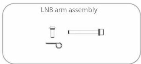
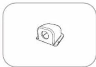
Cable clamp (1),Sems1 M4x10 (1) (x2 for Auto skew model) Sems2 M6x55 1
Controller Controller bracket, Rear cable cover
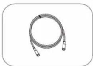
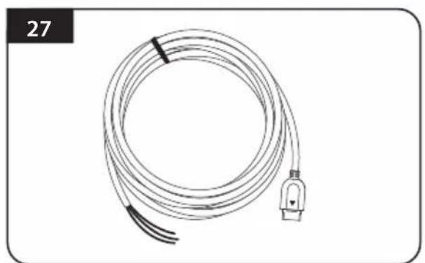
STB cable (3m)
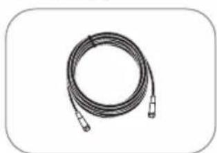
Signal cable (7m) (x2 for optional twin outputs)
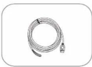
Power input cable
Cable holder
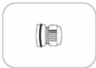
Cable gland Mounting plate
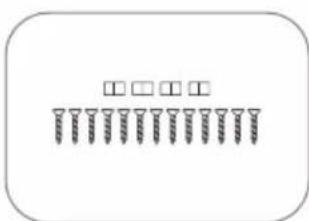
M4 × 20(13) , M8 locking nut(4)
LNB protection pad
User manual
Actual components may differ from the above images.
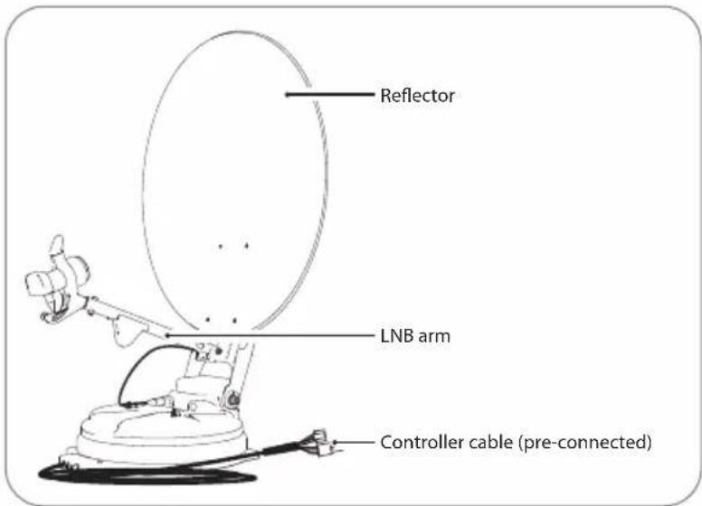
2-2. Name of parts
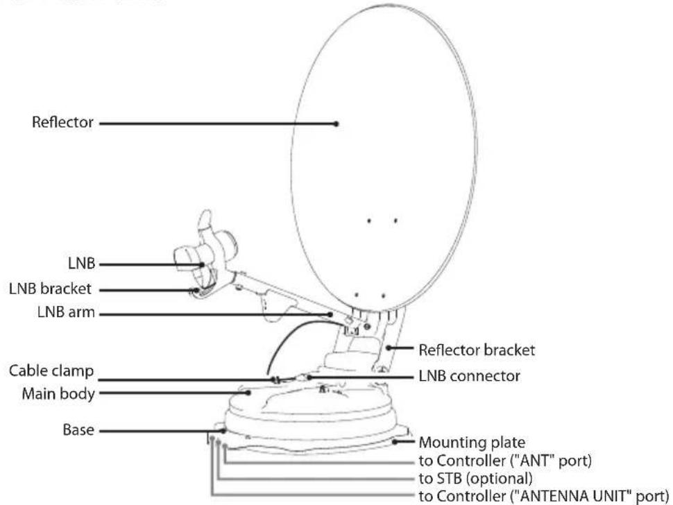
Parts of Main unit

Parts of Controller
- Front
Back
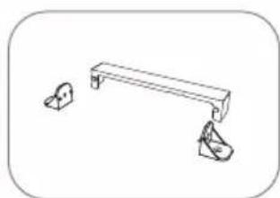
3. How to assemble
Step 1: Power on the unit and press SET at any satellite
Step 2: When reflector bracket is lifted up to vertical direction (about 90 degrees), turn the unit off
Step 3: Combine reflector with reflector bracket
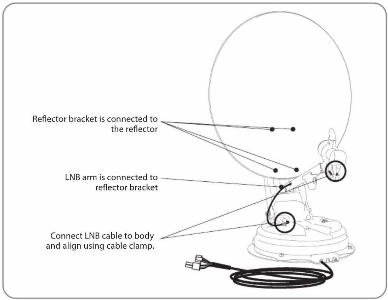
Step 4: Combine LNB arm with reflector bracket
Step 5: Connect LNB cable to the connector on the body, and cover the LNB connector with waterproof cap for protection
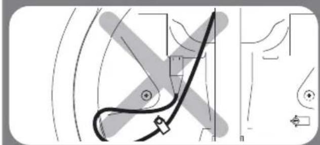
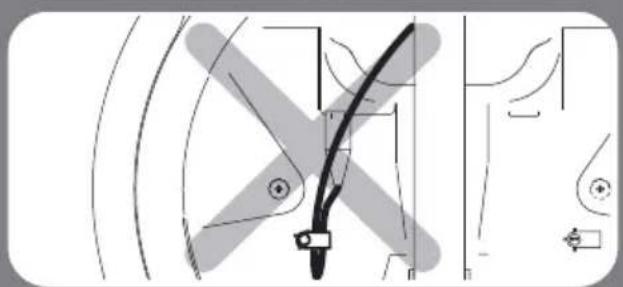
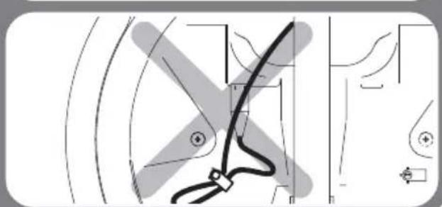
Step 6: Align LNB cable on the body using cable clamp
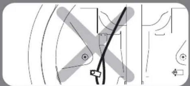
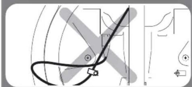
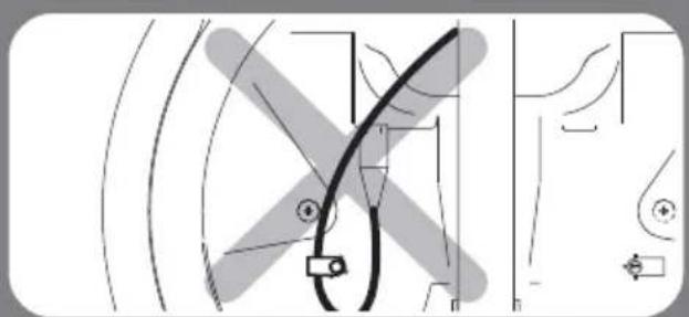
To avoid cable damage, installer has to fix LNB cable as enlarged image on following page 11.
Step 7: Power on and check the installation is completed as HOME positioning
- 65cm dish antenna
| No QuantityPart name | ||
| ① | Reflector | 1 |
| ② | LNB arm | 1 |
| ③ | Reflector bracket | 1 |
| ④ | M6 flat mold washer | 4 |
| ⑤ | Truss head M6x15 | 4 |
| ⑥ | SEMS2 M6x55 | 1 |
| ⑦ | Cable clamp | 1 |
| ⑧ | SEMS1 M4x10 | 1 |
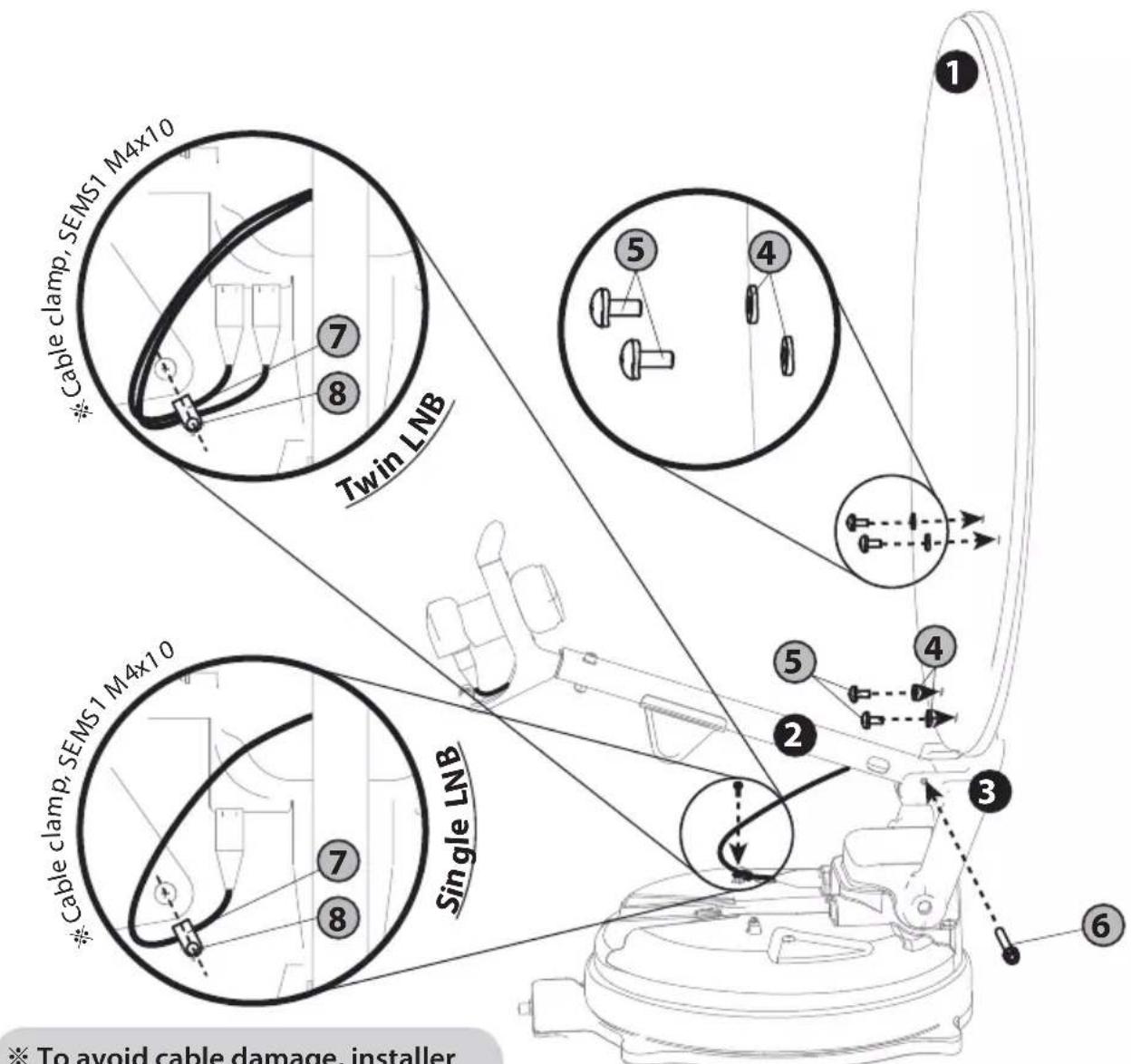
To avoid cable damage, installer has to fix LNB cable using cable clamp. Please refer to the detail at the next page.
- 85cm dish antenna
| No QuantityPart name | ||
| ① | Reflector | 1 |
| ② | LNB arm | 1 |
| ③ | Reflector bracket | 1 |
| ④ | M6 flat mold washer | 4 |
| ⑤ | Truss head M6x15 | 4 |
| ⑥ | SEMS2 M6x55 | 1 |
| ⑦ | Cable clamp | 1 |
| ⑧ | SEMS1 M4x10 | 1 |
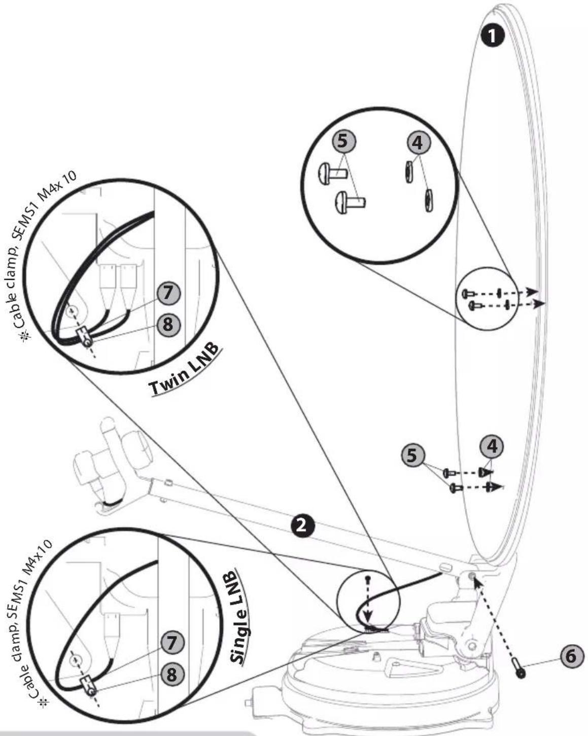
To avoid cable damage, installer has to fix LNB cable using cable clamp. Please refer to the detail at the next page.
- 65cm Auto skew dish antenna
| No QuantityPart name | ||
| ① | Reflector | 1 |
| ② | LNB arm | 1 |
| ③ | Reflector bracket | 1 |
| ④ | M6 flat mold washer | 4 |
| ⑤ | Truss head M6x15 | 4 |
| ⑥ | SEMS2 M6x55 | 1 |
| ⑦ | Cable clamp | 2 |
| ⑧ | SEMS1 M4x10 | 2 |
ENGLISH -9
- 85cm Auto skew dish antenna
| No QuantityPart name | ||
| ① | Reflector | 1 |
| ② | LNB arm | 1 |
| ③ | Reflector bracket | 1 |
| ④ | M6 flat mold washer | 4 |
| ⑤ | Truss head M6x15 | 4 |
| ⑥ | SEMS2 M6x55 | 1 |
| ⑦ | Cable clamp | 2 |
| ⑧ | SEMS1 M4x10 | 2 |
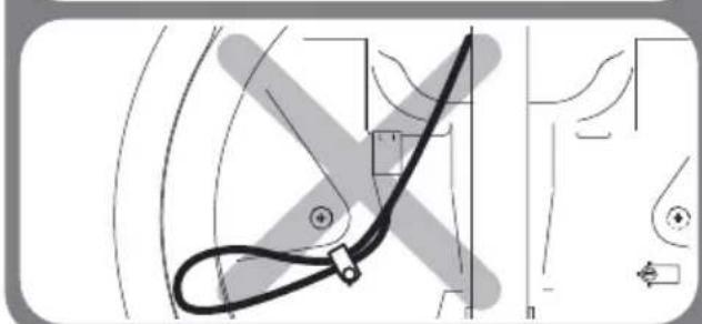
Good example
Bad example
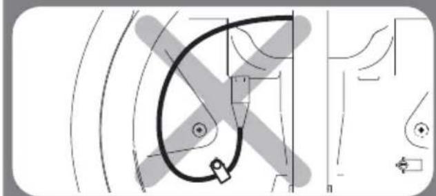
Bad examples are the same for Single LNB and Twin LNB.
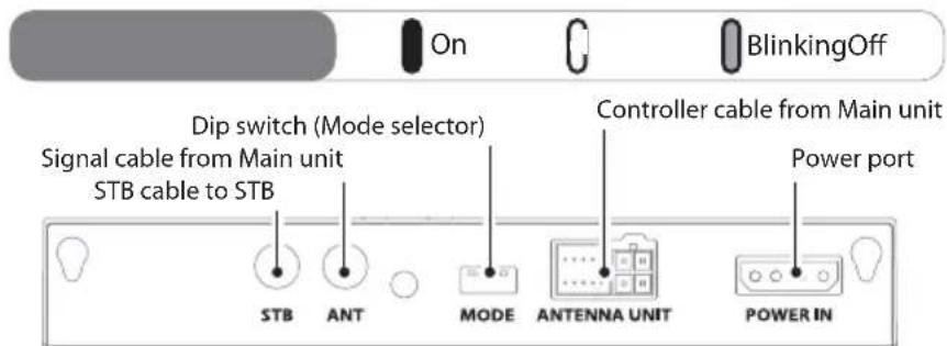
4. Connection diagram
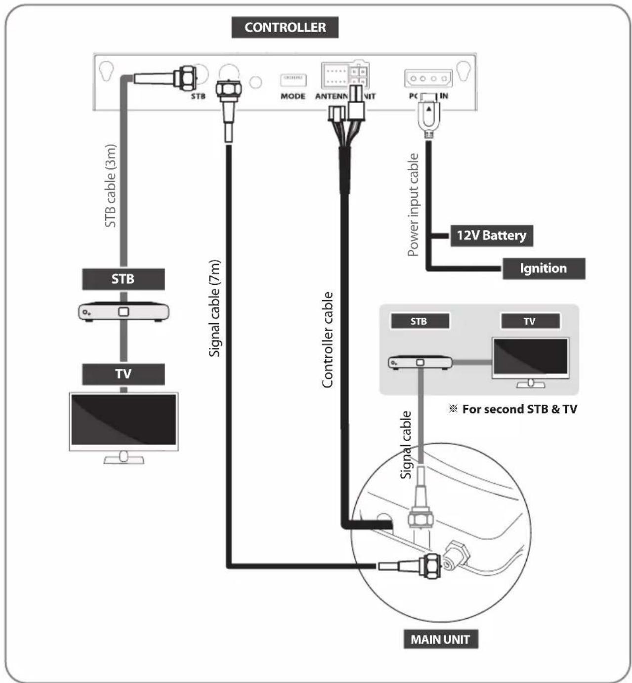
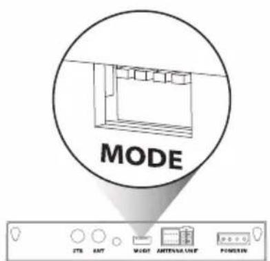
- Use controller cable to connect the antenna to the controller. Controller cable is pre-connected to the main body
- STB cable and signal cable have different lengths. Please check the lengths to use the correct cable for the job
- Please ensure the supplied cables are used and not modified in anyway
Additional STB can display the selected satellite channels at main STB and it cannot select or change the satellite. Main STB which is connected via controller is only supportive DiSEqC function.
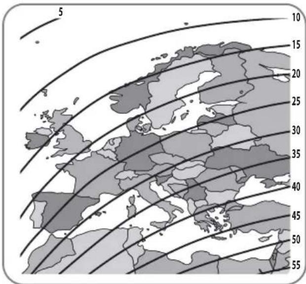
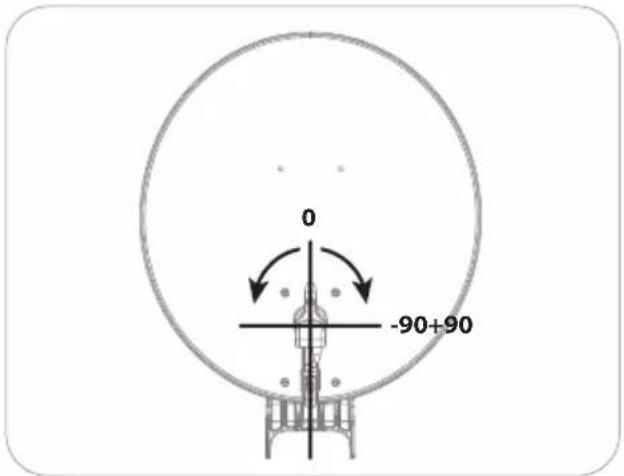
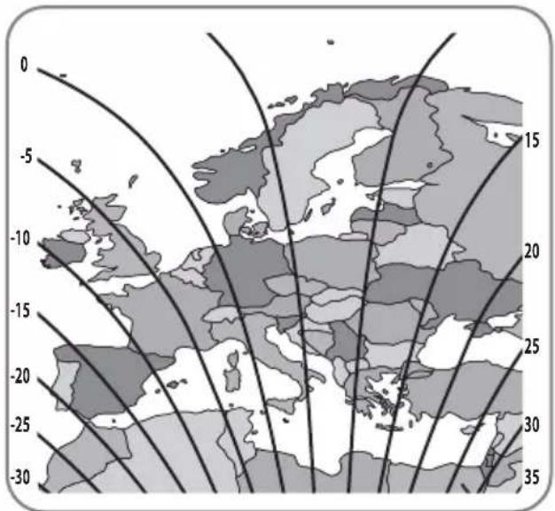
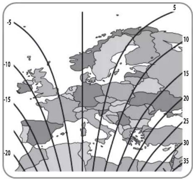
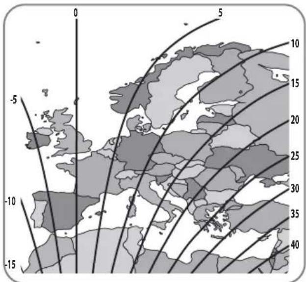
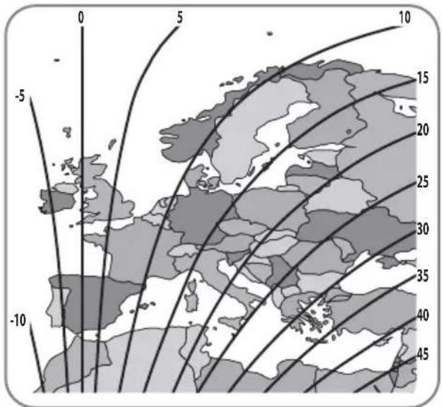
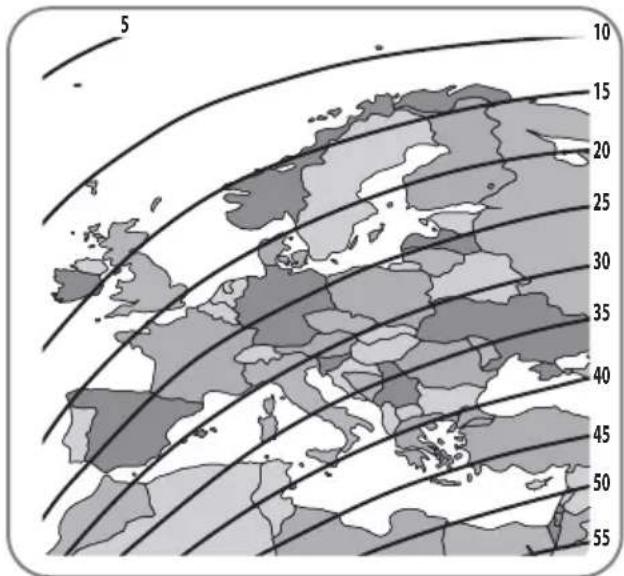
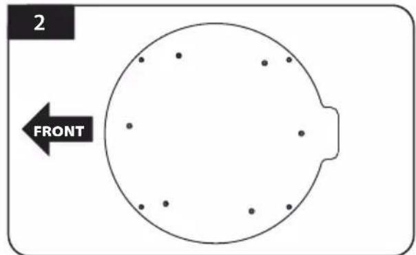
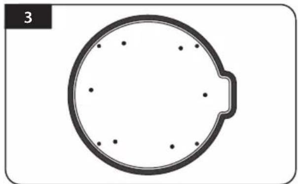
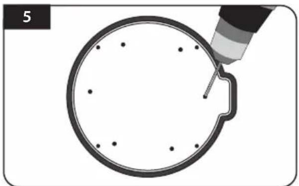
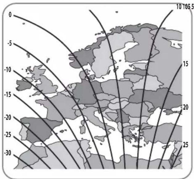
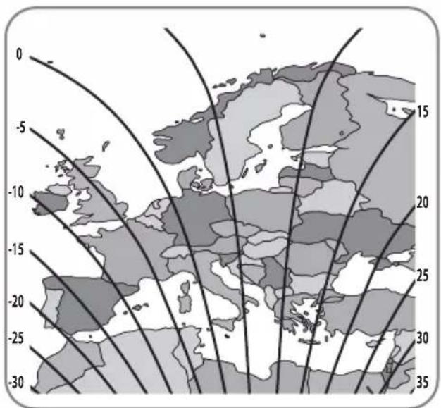
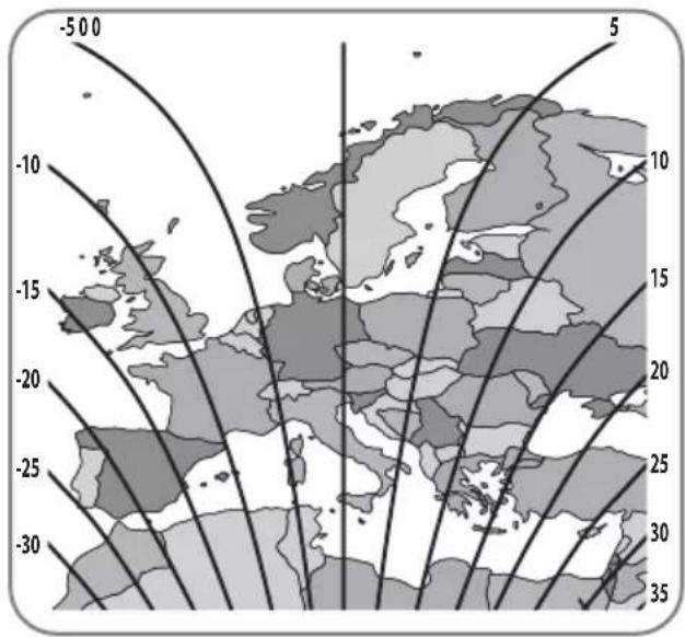
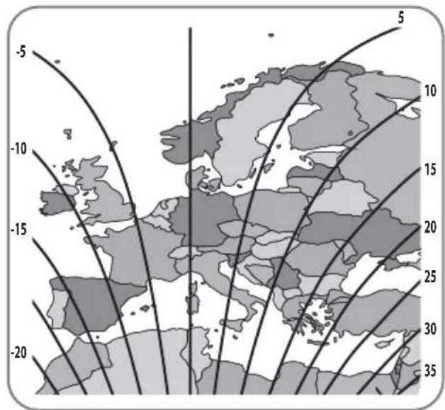
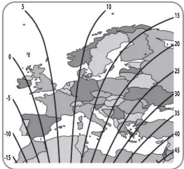
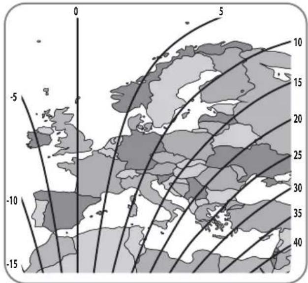
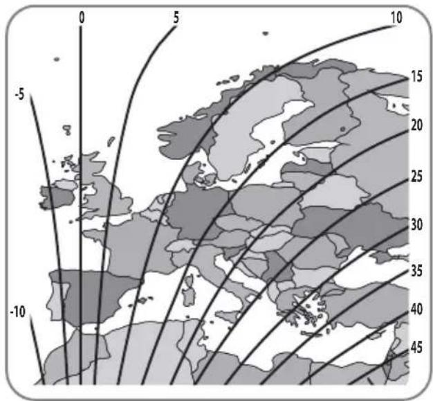
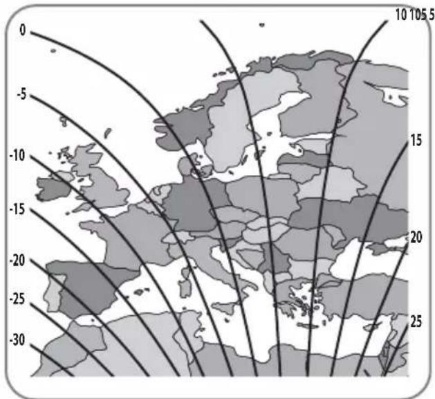
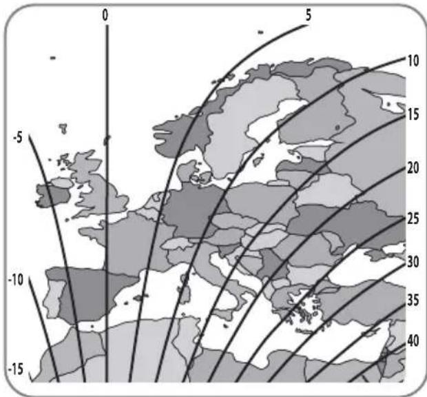
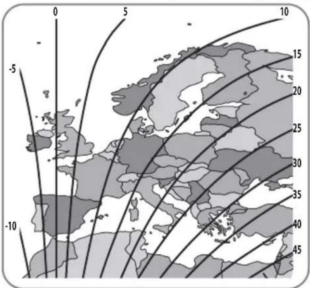
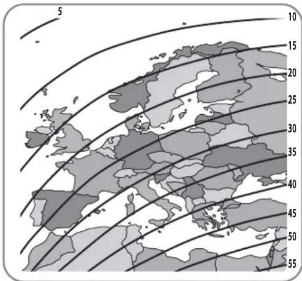
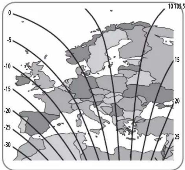
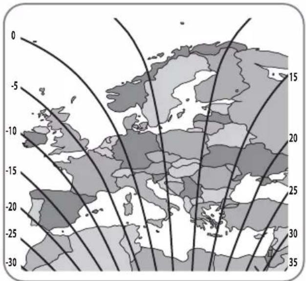
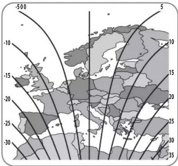
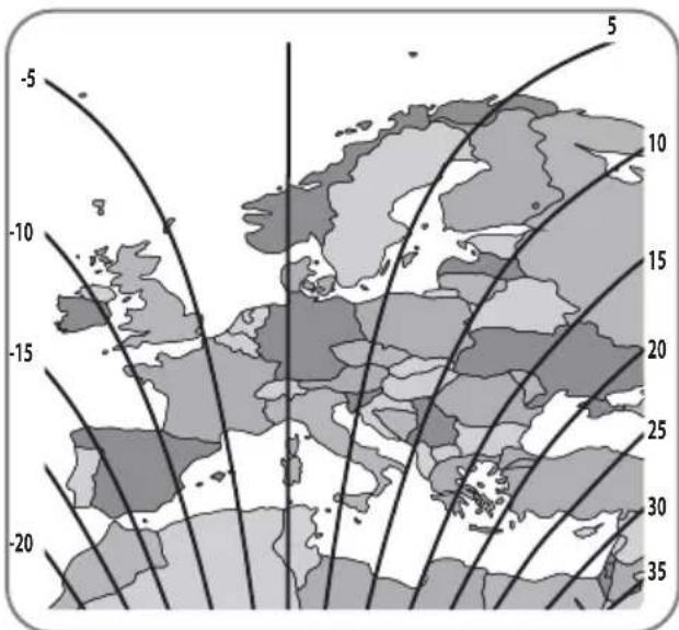
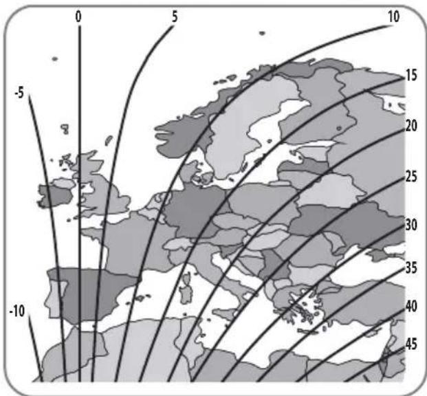
5. Skew adjustment
For SNIPE DISH standard models only. No need for Auto skew models.
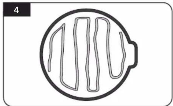
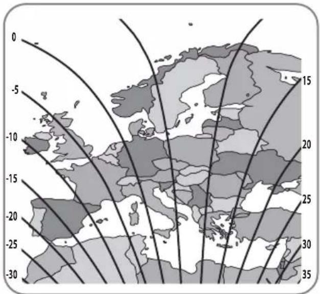
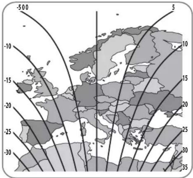
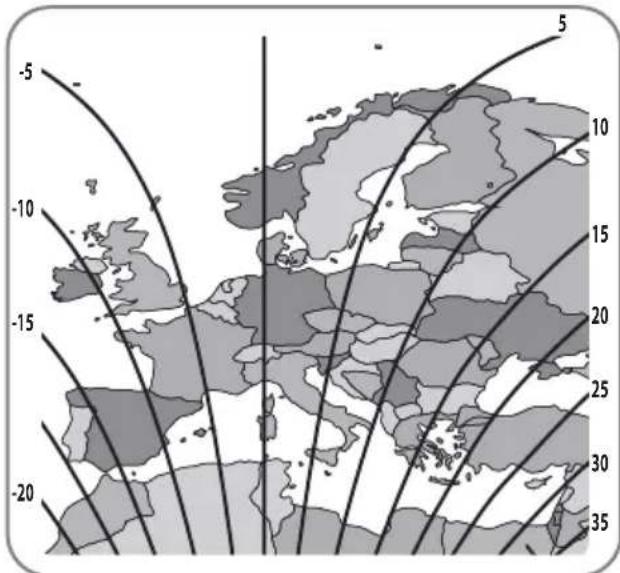
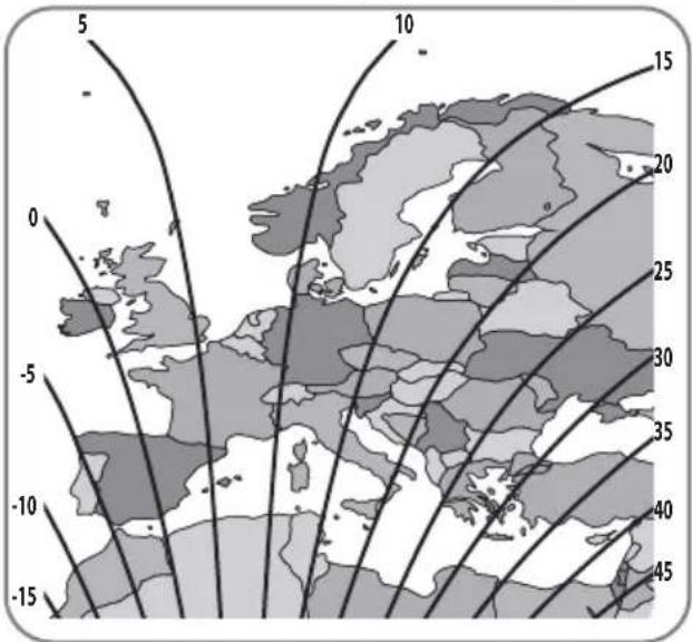
The LNB at the end of the satellite picks up either horizontal or vertical signal. To change horizontal to vertical signal, turn the LNB as 90^ (vice versa).
Skew adjustment is required according to target satellites and regions. For the best signal quality, adjust skew by referring to the below images.
Accuracy is not important, so small tolerance will be acceptable. It will be easy to check the satellite's signal quality on STB with turning the LNB little by little.
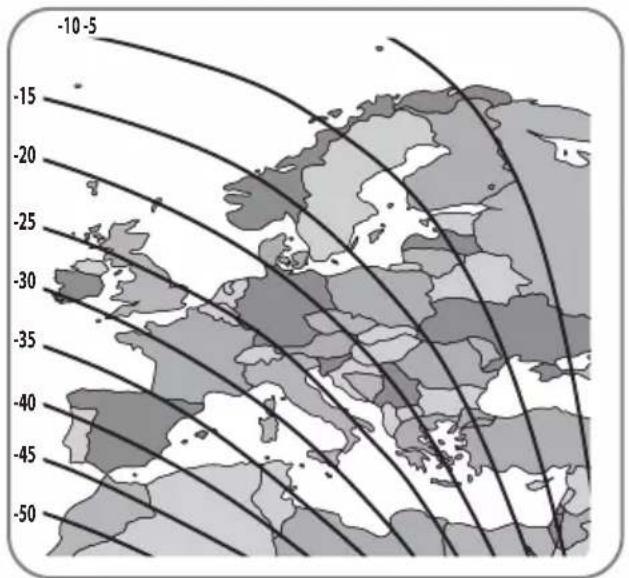
Turksat @ 42.0°E Astra2 @ 28.2°E
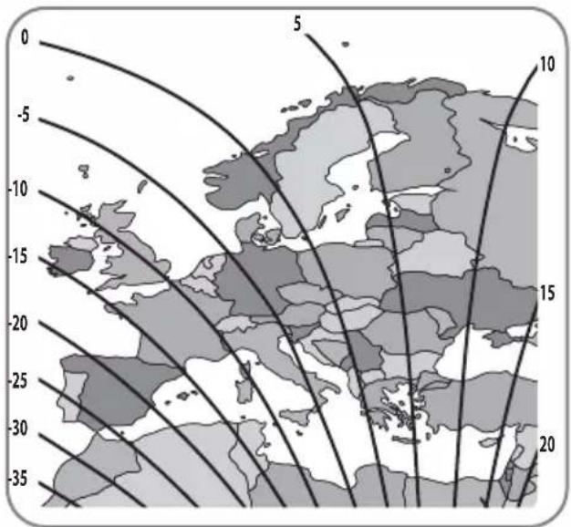

Astra3 @ 23.5°E Astra1 @ 19.2°E

HotBird @ 13.0°E Eutelsat 9 @ 9.0°E

Astra4 @ 4.9°E Thor @ 0.8°W
Eutelsat 5W @ 5.0°W Hispasat @ 30.0°W
6. Functional description
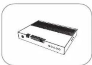
6-1. Get ready to use
See below table to find the model and match the controller has correct pre-setting as needed.
You should leave as it is and do not change setting as own discretion unless mismatch with the model
Controller Back
| Antenna Model | 65cm | 85cm |
| Standard | #2 down 1 2 3 4 | #1 down 1 2 3 4 |
| Auto skew | #2,4 down 1 2 3 4 | #1,4 down 1 2 3 4 |
※ Incorrect setting causes deterioration of reception performance.
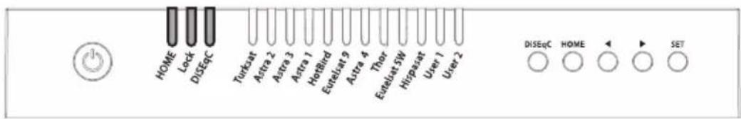
a. All satellite LEDs blink and then system is displayed like below image
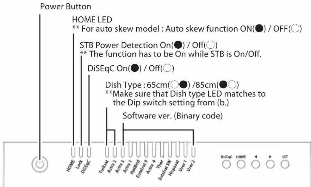
b. When HOME LED becomes solid this means the antenna is ready to operate (If the antenna is not at HOME, HOME LED blinks while coming back HOME)
c. To power on the unit, press POWER button and check LEDs are lit. To power off the unit, press and hold POWER button till all LEDs are lit, the unit will be off when the button is released
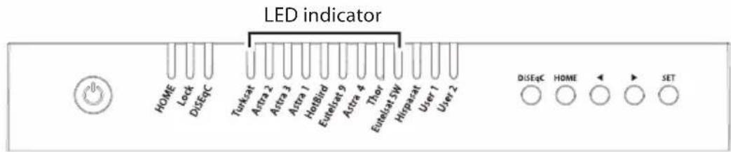
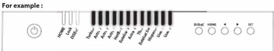
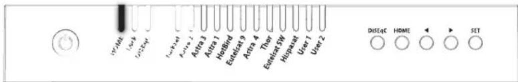
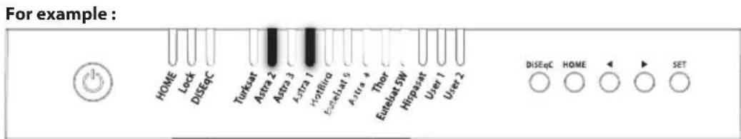
6-2. Searching the satellite
a. Go to the target satellite using arrow buttons and press SET to search
b. Lock LED blinks during searching process and becomes solid when the target satellite is locked
For example :
c. If wrong satellite is selected, move to the correct satellite and press SET to confirm the new satellite
d. After use or before travelling, press HOME for HOME positioning
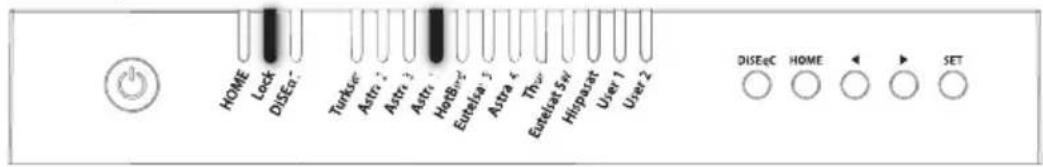
6-3. DiSEqC 1.1 setting
Refer SNIPE DISH's pre-set satellites for DiSEqC 1.1. when user setup at STB
a. The default setting for DiSEqC is ON, DiSEqC LED is on.
To switch the function ON/OFF, make sure that antenna is at HOME and press DiSEqC button for 2 seconds. (See also DiSEqC LED status changes between ON and OFF.)
b. For DiSEqC operating of the antenna, STB has to have matching satellite list as SNIPE DISH's pre-set list. User needs to assign satellites in same order (#1~12 in the above table) at STB's DiSEqC setting to be ready for DiSEqC function use.
6-4. STB power detection On/Off
a. Ensure that the unit is turned off
b. Press and hold Right Arrow button and turn on the Power button
c. When HOME LED becomes solid this means the function change is finished (If the antenna is not at HOME, HOME LED blinks while coming back HOME)
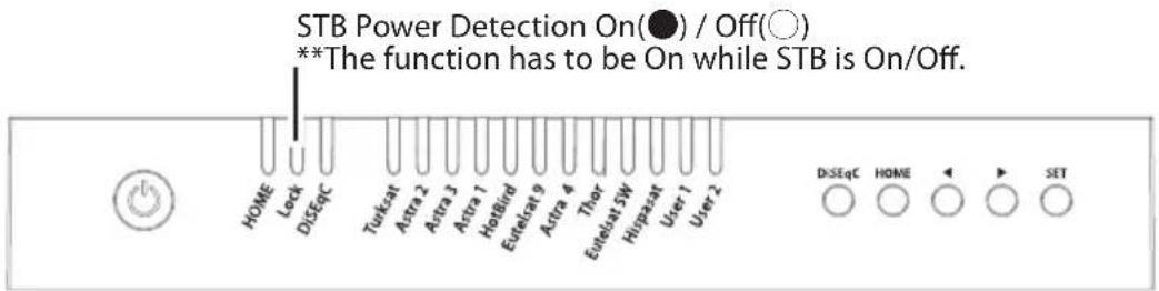
When STB power detection (Lock LED) is ON,
- STB which is connected controller should be on for operating antenna
- If STB is turned off while antenna is operating, antenna goes back to HOME and do not operate
- If STB is turned off, the antenna does not operate despite the controller SET button is pressed
When STB power detection (Lock LED) is OFF,
- Antenna is operated with controller regardless of STB's power state
6-5. Power save mode
a. While antenna is at HOME, antenna turns off automatically if there is no input from controller for 15 minutes
b. Press POWER button to turn on for operating again
7. Extra functions
7-1. Error message
Error message LEDs (HOME / Lock / DiSEqC) will be illuminated at the same time if there is a problem with the main unit and detail is indicated as :
| NO LED in | indicator Error detail | |
| 1 | Turksat | Low power |
| 2 | Astra 2 | Tuner error |
| 3 | Astra 3 | AZ motor error |
| 4 | Astra 1 | EL motor error |
| 5 | Hotbird | SK motor error |
| 6 | Eutelsat 9 | AZ motor current error |
| 7 | Astra 4 | EL motor current error |
| 8 | Thor | SK motor current error |
| 9 | Eutelsat 5W | EL range error |
7-2. Factory reset
a. Ensure that the unit is turned off
b. Press and hold HOME button and turn on the Power button
c. Factory reset takes less than 10 seconds
d. When HOME LED becomes solid this means the function change is finished (If the antenna is not at HOME, HOME LED blinks while coming back HOME)
7-3. Software upgrade
a. Transfer "GALAXY.BIN" file to a USB stick. Do not place inside a folder
b. Ensure that the unit is turned off and plug the USB into USB port
c. Press and hold SET button and turn on the Power button
d. HOME / Lock / DiSEqC LEDs blink together while checking upgrade file
e. Software upgrade takes about 10 seconds
f. When the upgrade is completed, all Satellite LEDs flash once, then HOME / Lock / DiSEqC LED is off, controller is rebooted
g. When HOME LED becomes solid this means the antenna is ready to operate
h. If upgrade is failed, HOME / Lock / DiSEqC LEDs blink 5 times and back to the previous system

※ Use FAT32 format USB only.
CBI type USB is not supported.
7-4. Manual satellite update function
In case there is specific satellite with an error, update satellite information manually with the below instruction.
a. Press the next satellite of the satellite with an error to search
- For Turksat, Astra 2 is only the option
- For Hispasat, Eutelsat 5W is the only option
- For the rest satellites, each has two options on both side
b. Once the next selected satellite is found (locked), go to the satellite with an error and press SET button longer than 2 seconds
- Make sure that Lock LED blinks quicker than per second while update If the button is pressed less than 2 seconds, Lock LED blinks as normal operation
c. If update is succeeded, all satellite LEDs blink twice and automatically start to search the satellite
d. If update is failed, antenna goes back to HOME position
- Select the another option of next satellites and proceed update as the above procedure again
- If second trial is failed, check the manual for software upgrade

- If upgrade or factory reset is applied, all stored data will be removed.
8. Trouble shooting
There are a number of common issues that can affect the signal reception quality or the operation of the unit. The following sections address these issues and potential solutions.
A. No function when power on the controller
i. Check again all the cable connections have been made correctly.
- Connection between the power and controller.
- Connection between the controller and antenna. Make sure that the left port of the antenna is connected to the controller.
ii. Check if the power input cable has been damaged.
iii. Check the battery polarities (+ / - )
B. Fail to search the selected satellite
i. Satellite signals can be blocked or degraded by buildings, trees. Make sure there are no obstructions in a southward direction.
ii. Select another satellite if this locks then select your desired satellite.
iii. Turn the unit off and then back on again and select desired satellite.
C. Mechanical problems
i. If the antenna does not move into desired position.
- Try to power OFF/ON again.
ii. If the antenna makes a noise while remaining static.
- Try to power OFF/ON again. If problem persists, please contact local dealer/shop for assistance.
D. Other issues
i. If the system has been improperly wired, it will not operate properly. Contact local dealer/shop for assistance of cable damage.
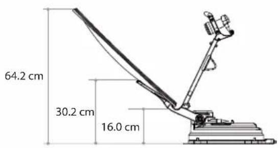
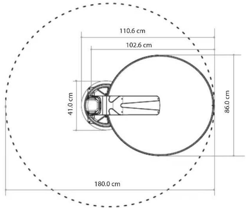
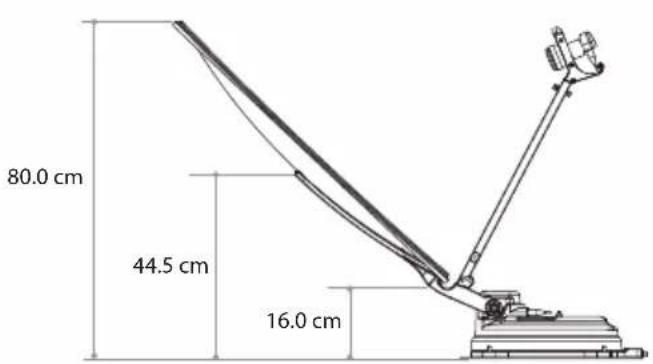
9. Specifications
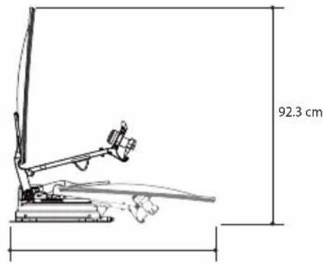
9-1. Dimension
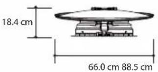
SNIPEDISH65
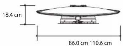
SNIPE DISH 85
9-2. Specifications
| MODEL | SNIPE DISH 65 | SNIPE DISH 85 | |
| Input Satellite Frequency | 10.7 ~ 12.75 GHz | 10.7 ~ 12.75 GHz | |
| Polarization | Vertical & Horizontal | Vertical & Horizontal | |
| Typical Dish Size | 65 cm | 85 cm | |
| Size (W x L) | 66.0 x 71.0 cm (Offset Dish) | 86.0 x 91.0 cm (Offset Dish) | |
| Dimensions (L x W x H) | 88.5 x 66.0 x 18.4 cm (Folded) | 110.6 x 86.0 x 18.4 cm (Folded) | |
| Weight | 12 kg | 13.8 kg | |
| Min EIRP | 46 dBW | 44 dBW | |
| Angle Range (EL / AZ) | 0° ~ 145° / 390° | 0° ~ 145° / 390° | |
| Angle Range (Skew) | Manual / Auto (Optional) | Manual / Auto (Optional) | |
| Satellite Searching Time | 180 seconds (Average) | 180 seconds (Average) | |
| Output | 1 / 2 output (Optional) | 1 / 2 output (Optional) | |
| LNB | Output Frequency | 950 ~ 2,150 MHz | 950 ~ 2,150 MHz |
| L.O. Frequency | 9.75 / 10.6 GHz | 9.75 / 10.6 GHz | |
| Operating Temperate | -20°C ~ +60°C | -20°C ~ +60°C | |
| Input Voltage | DC 12V | DC 12V | |
| Power Consumption | 50 W (in searching) | 50 W (in searching) | |
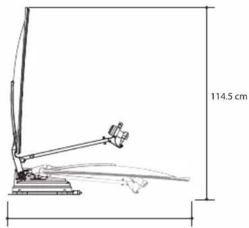
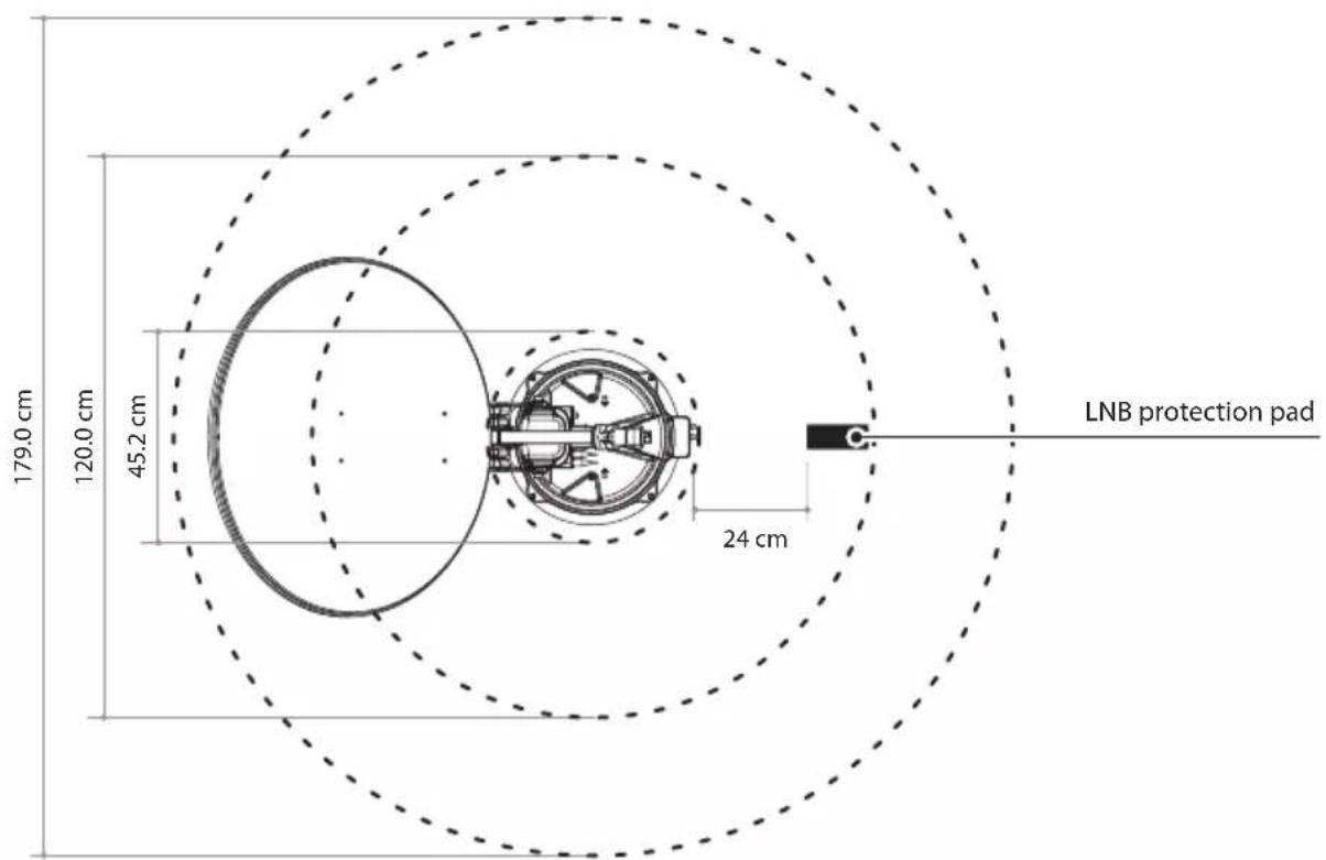
10. Caravan/Motorhome installation
10-1 . Required space for the NIPE DISH
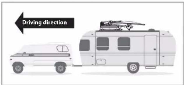
Take care, that there is enough space for the fold SNIPE DISH, just as for the operation range(cruising radius).
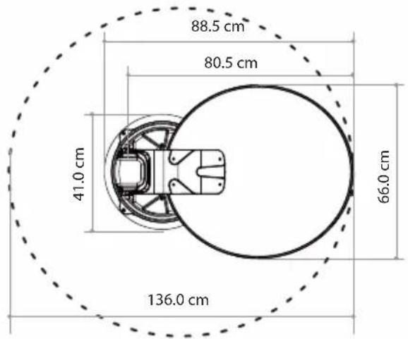
SNIPEDISH65

drnnnne

Driving direction
ENGLISH-23
10-2. Equipment for installation
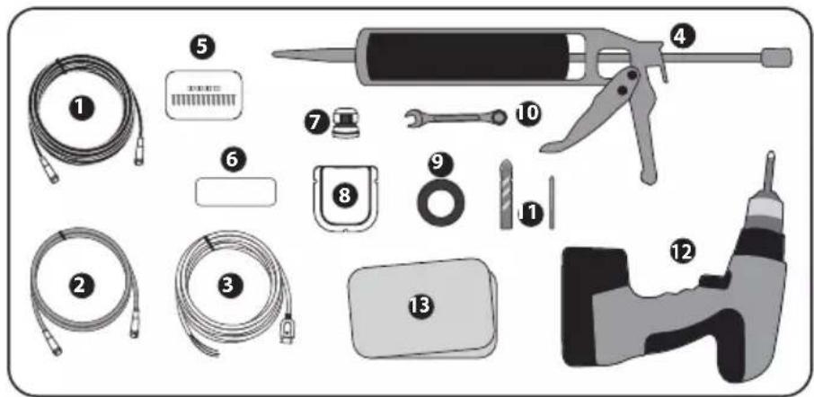
Signal cable
STB cable
3 Power input cable
Silicone
M4×20(13), M8 locking nut(4)
6 LNB protection pad
7 Cable gland
8 Cable holder
9 Masking tape
10 Spanner
12mm drill bit, 25mm drill bit
12 Power drill
13 Cleaner
10-3. Instruction for installation
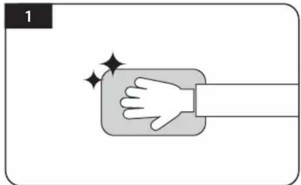
Clean the surface with cleaner
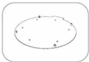
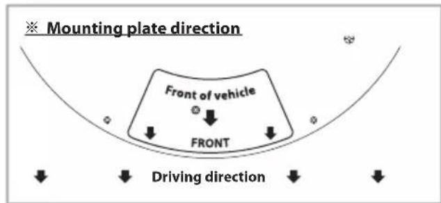
Locate mounting plate in the centre of the vehicle roof
Attach masking tape outside of the mounting plate by 5mm away from the plate edges
Put aside the mounting plate to apply silicone within the attached tape line but leave 2cm inward gap from the line
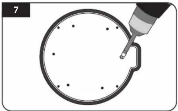
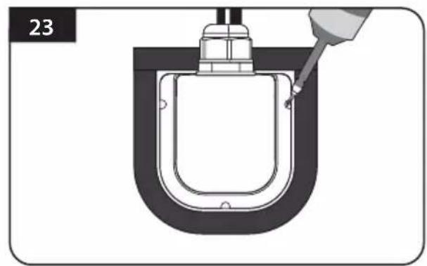
Place the mounting plate on the silicone and make 6 holes (2mm) with a power drill
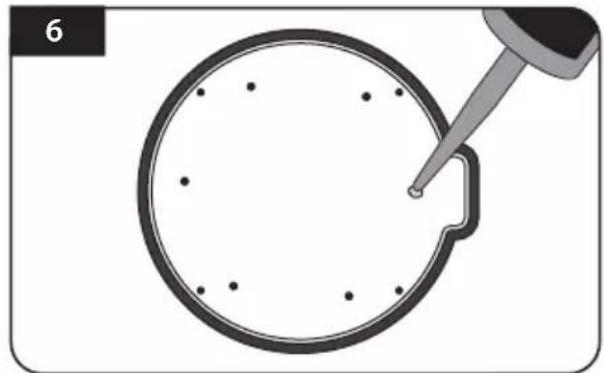
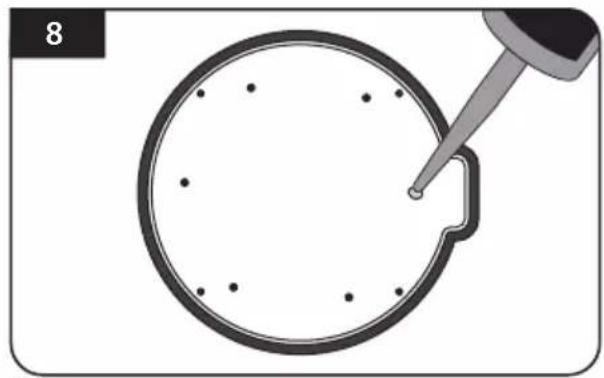
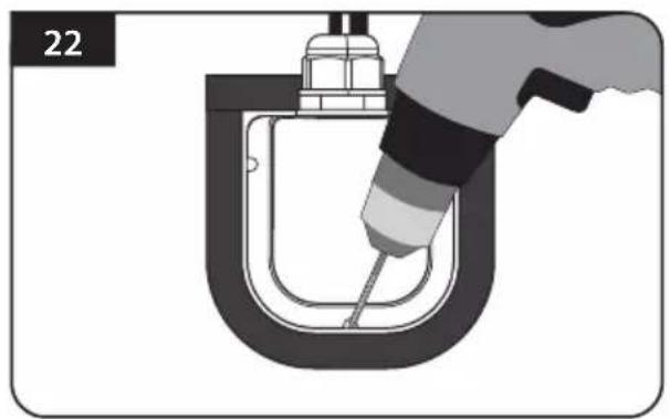
Apply silicone on the holes
Screw bolts Re-apply silicone to cover screwed bolts
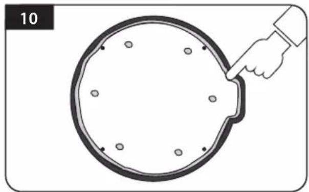
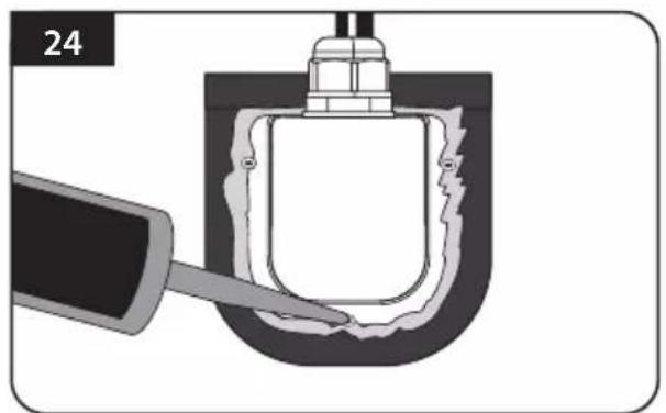
Clean away the excess silicone
Apply silicone around mounting plate edge
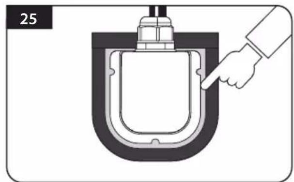
Remove masking tape and allow to dry
Prepare to place the antenna on to the four upright bolts
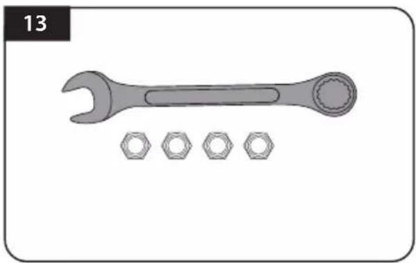
Parts required, spanner, four(4) nuts
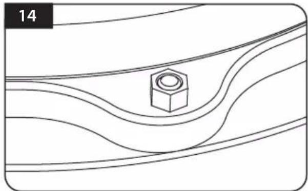
Place the antenna on the aluminium plate and place the washers over each bolt
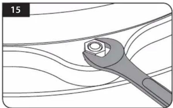
Fit the supplied nuts to each of the four bolts and tighten firmly with spanner
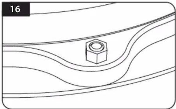
Make sure you check and four (4) nuts are tightened
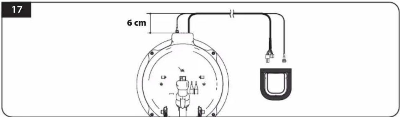
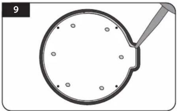
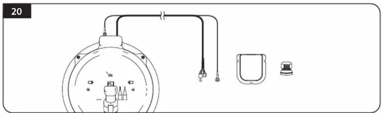
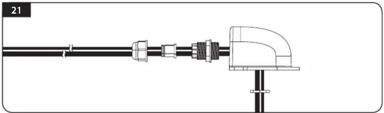
Connect signal cable to antenna port and place cable holder bottom next to the center of the antenna base and then apply masking tape 5mm from the outside of the cable holder bottom
- To prevent the damage of cable, cable shaping is necessary. By referring the above image, arrange the cable from the antenna base port straight in 6cm , and then bend it to cable holder bottom.
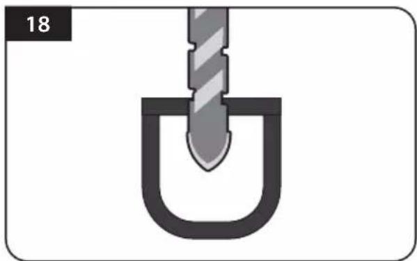
Drill a 25mm hole in the centre of the tape marking
Make sure that hole size is minimum so that the cable can pass through
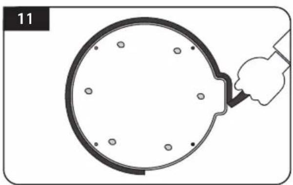
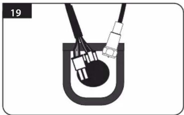
Get controller cable and signal cables, cable holder and gland for installation
Put the cable inside the cable holder as above picture
Place the assemble cable holder inside the tape markings. Drill three(3) 2mm holes
Fix cable holder on the vehicle roof with three(3) of M4 x 20 screws at drill holes made
Apply silicone around cable holder and on the top of the screws for waterproof
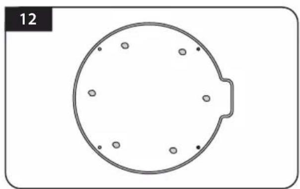
Connect cables to fassigned and remove masking tape then tidy silicone before dry
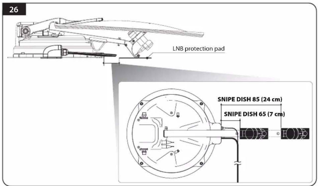
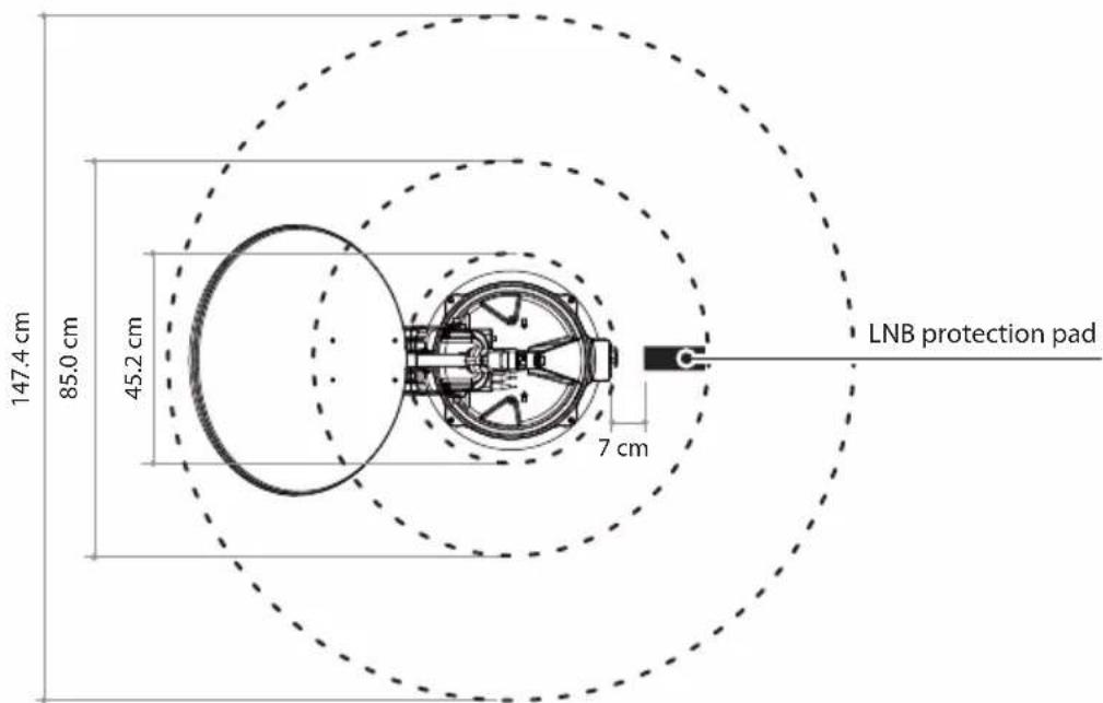
Attach LNB protection pad on the point which is apart 7 cm (24 cm in SNIPE DISH 85) from antenna base. Check that LNB protection pad is correctly placed where LNB bracket touches on the vehicle roof
To prevent entanglement of cables, make sure antenna LNB cable does not be touched by the LNB protection pad.
Get power input cable for battery connection

Match the power cables polarities to the battery polarities, red to red / back to black and yellow ignition cable to ignition port of the vehicle
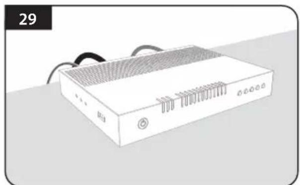
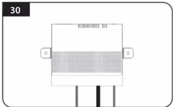
Plug the cables to the controller (Power, signal, STB and controller cables)
Place the controller at where user wants with four(4) of M4 x 20 screws
Inhaltsverzeichnis
Astra3 @ 23.5°E Astra1 @ 19.2°E
HotBird @ 13.0°E Eutelsat 9 @ 9.0°E
Astra4 @ 4.9°E Thor @ 0.8°W
Eutelsat 5W @ 5.0°W Hispasat @ 30.0°W

9. Specifications techniques
9-1. Dimension 21
9-2. Specifications techniques 21
Astra3 @ 23.5°E Astra1 @ 19.2°E
HotBird @ 13.0°E Eutelsat 9 @ 9.0°E
Astra4 @ 4.9°E Thor @ 0.8°W
Eutelsat 5W @ 5.0°W Hispasat @ 30.0°W
9-2. Specifications techniques
Astra3 @ 23.5°E Astra1 @ 19.2°E
HotBird @ 13.0°E Eutelsat 9 @ 9.0°E

Astra4 @ 4.9°E Thor @ 0.8°W

Eutelsat 5W @ 5.0^ W Hispasat @ 30.0^ W