Caravan Plus - Receiver Selfsat - Free user manual and instructions
Find the device manual for free Caravan Plus Selfsat in PDF.

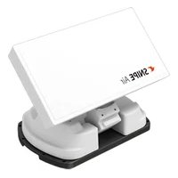
| Product Type | Satellite receiver with motorized antenna |
| Dimensions (L x W x H) | 573 x 508 x 149 mm |
| Reflector Size (L x W) | 573 x 450 mm (with rim) |
| Weight | 5.5 kg |
| Power Supply | 12 V DC (vehicle battery or adapter) |
| Power Consumption | 11 W (normal) / 30 W (max) / 3.6 W (standby) |
| Input Frequency | 10.7 to 12.75 GHz |
| Antenna Gain | 35.0 dBi @ 12.7 GHz |
| Polarization | Horizontal / Vertical |
| Number of LNB Outputs | 1 or 2 (optional) |
| Connectivity | Bluetooth for SAT CONNECT app |
| Main Functions | Automatic satellite search, control via buttons or app, return to HOME position |
| Installation | Mounting on caravan/motorhome roof |
| Maximum Speed in Transit | 130 km/h |
| Maintenance | No regular maintenance; any service by authorized center |
| Safety | Ensure antenna is folded before moving the vehicle; do not use in car wash |
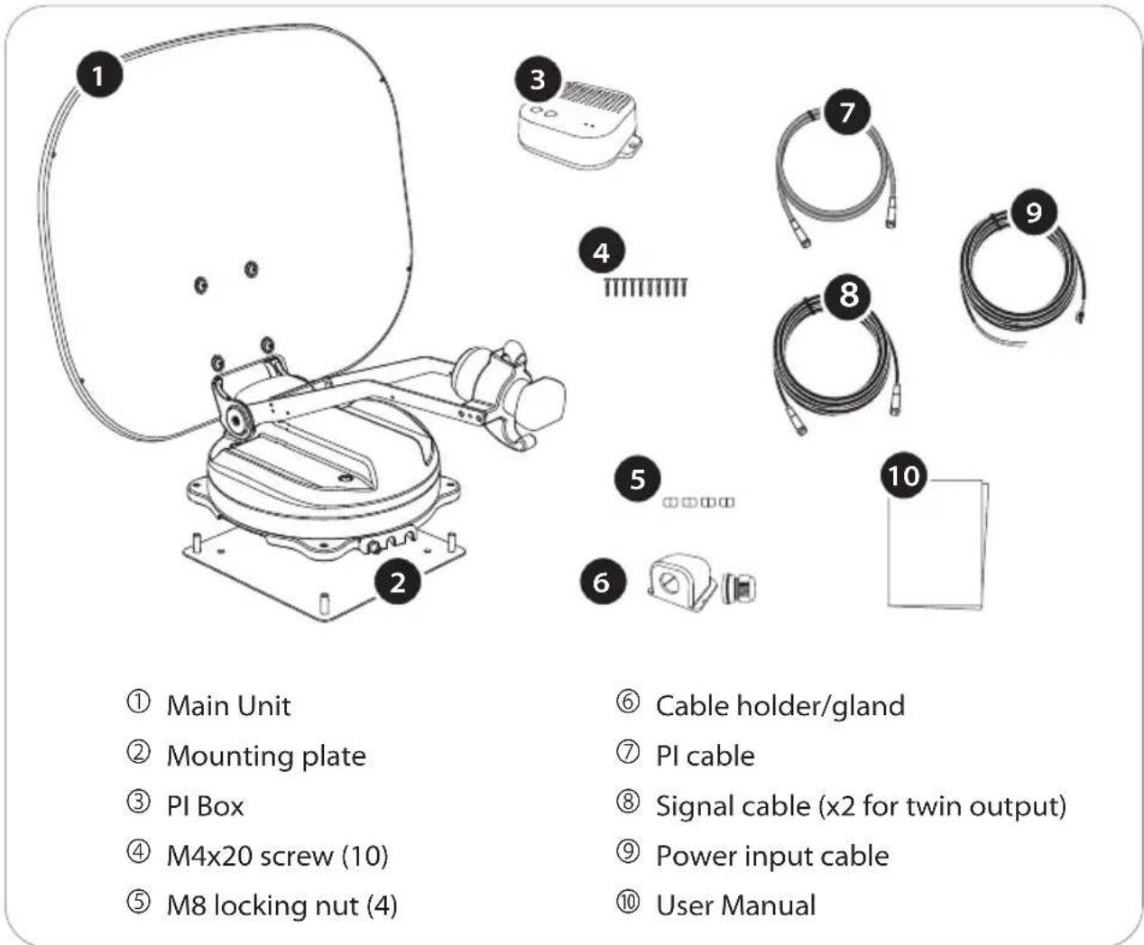
| Included Parts | Main unit, mounting plate, PI box, screws, nuts, cables |
| Warranty | Contact your local dealer |
Frequently Asked Questions - Caravan Plus Selfsat
User questions about Caravan Plus Selfsat
0 question about this device. Answer the ones you know or ask your own.
Ask a new question about this device
Download the instructions for your Receiver in PDF format for free! Find your manual Caravan Plus - Selfsat and take your electronic device back in hand. On this page are published all the documents necessary for the use of your device. Caravan Plus by Selfsat.
USER MANUAL Caravan Plus Selfsat
natural_image
Technical line drawing of a satellite or radar system mounted on a base (no text or symbols visible)ENGLISH : User's manual
637, Smart-Hub Industry-University Convergence Center, 237 Sangidaehak-ro, Siheung-si, Gyeonggi-do, Korea
TEL: +82 31 8041 1500 FAX: +82 31 8041 1550 E-MAIL: sales@selfsat.com
I DO IT France
2. Operating Instruction
2-1. Connection Diagram 4
2-2. How to Use 5
2-3. How to Use APP 6
3. Skew adjustment 8
4. Troubleshooting 10
5. Specifications
5-1. Dimension 11
5-2. Specifications 12
6. Caravan/Motorhome Installation
6-1. Required space for installation 13
6-2. Equipment for installation 14
6-3. Instruction for installation 15
1. General Information
1-1. Proper use and operation
These instructions describe the functions and operation of CARAVAN PLUS, auto search satellite system.
Please read the user manual carefully before starting the installation.
Correct and safe operation of the system can only be ensured by following instructions.
- The unit is programmed to automatically move in a direction that can to receive preset satellite TV signal. For general operation, ensure that the system is in a position with a clear view of the sky. If the satellite's signal is interrupted by obstacles such as mountains, buildings or trees, no TV signal will be received.
- Installation must be performed by sufficiently qualified personnel.
- The manufacturer does not take liability for direct or indirect consequential damage of the system, motor vehicles or other equipment by reason of unsuitable battery usage or erroneous installation or wrong wire connection.
- As the user of this equipment, you are responsible for yourself ensuring compliance with the relevant laws and regulations of the automotive industry must be observed and complied with.
- The power is supplied by a standard vehicle electrical system with a rated voltage of 12VDC. For portable use, optional power adaptor produced by manufacturer must be used.
- This product has been designed for fixed installation on vehicles with maximum speeds of 130 km/h.
- Use of the equipment for purposes other than its intended use is not permitted. The use of any other parabolic reflectors or LNBs to those originally installed is not allowed.
- The product does not require any regular maintenance; all service must be carried out at approved service centers.
- For more information on general use of this unit consult local dealer for assistance.
SAFETY NOTE
Failure to follow the user manual may cause damage to the unit or user's vehicle, and responsible may be liable for further damage to the equipment.
- The PI BOX must not be exposed to dripping, splashing or other liquids.
- Do not allow children to play with plastic bags or other packaging materials. There is a risk of suffocation.
- The outdoor unit should only be installed on hard surfaces.
- There is a risk of damage when using the antenna in a storm or strong wind.
- The driver of the vehicle must visually verify that the antenna is fully folded by inspecting the antenna unit before driving off.
- Avoid cleaning user's vehicle with the mounted satellite system in a drive-through car wash or a car wash with a high-pressure cleaner.
1-2. Package
WARNING
natural_image
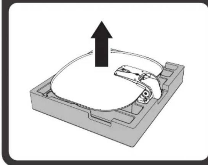
3D mechanical component diagram showing a housing with an upward arrow indicating motion or force (no text or symbols)Open the box and remove the packaging material. When taking the main unit from the box, hold it by the body, not the reflector, and lift it straight up.
Check the correct operating voltage of the power supply before commissioning. Please uses the device included in the package or use the manufacturer's authorized power supply.
2. Operating Instruction
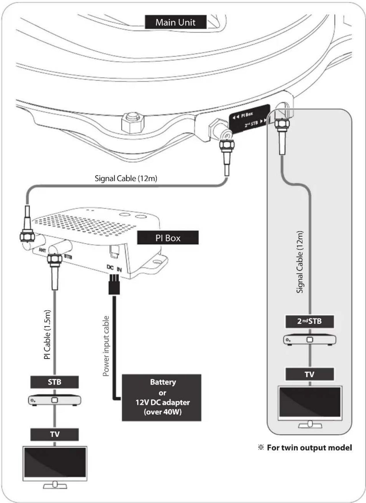
2-1. Connection Diagram
flowchart
graph TD
    A["Main Unit"] --> B["PI Box"]
    B --> C["2nd STB"]
    C --> D["Signal Cable (12m)"]
    D --> E["PI Box"]
    E --> F["STB"]
    F --> G["TV"]
    G --> H["Battery or 12V DC adapter (over 40W)"]
    H --> I["Power input cable"]
    I --> J["PI Cable (1.5m)"]
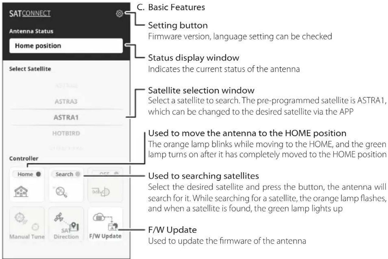
2-2. How to Use
1. Search satellites
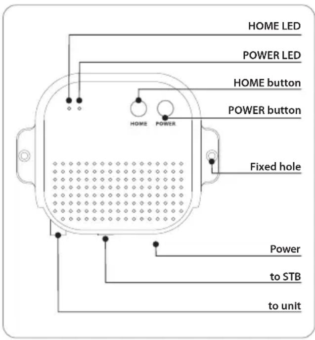
When powered on by pressing the PI BOX's power button, after about 10 seconds, the antenna starts searching for pre-programmed or most recently received satellite.
※ The pre-programmed satellite is ASTRA1, which can be changed to the desired satellite via the APP
a. When the antenna is in the HOME position, it starts searching for satellite.
b. When the antenna is pointing towards the satellite, it will not move.
c. When the antenna is in a different position than in the case of a and b above, it first moves to the HOME position and then starts searching for satellite.
d. If the antenna does not find a satellite for 10 minutes, the antenna returns to its HOME position.
e. Want to search for satellites again, reboot the PI BOX.
2. Power off
a. Press POWER button
Press and hold the power button of the PI BOX for more than 2 seconds, the power is turned off regardless of the state of the antenna.
b. Press HOME button
When the home button of PI BOX is pressed the antenna moves to the HOME position and the power is automatically turned off after about 60 seconds (the POWER LED and the HOME LED will blink alternately for 60 seconds)
c. Ignition Occurred
When ignition occurs in the vehicle, the antenna automatically moves to the HOME position and power off after 60 seconds. (If the PI BOX is turned off at this time, it will automatically turn on and then perform the operation.)
WARNING
If the PI BOX is powered off and the vehicle is moved while the antenna is not in the HOME position, the antenna may be damaged.
Before moving the vehicle, first check the condition of the antenna, and turn off after is fully folded to the HOME position.
2-3. How to Use APP
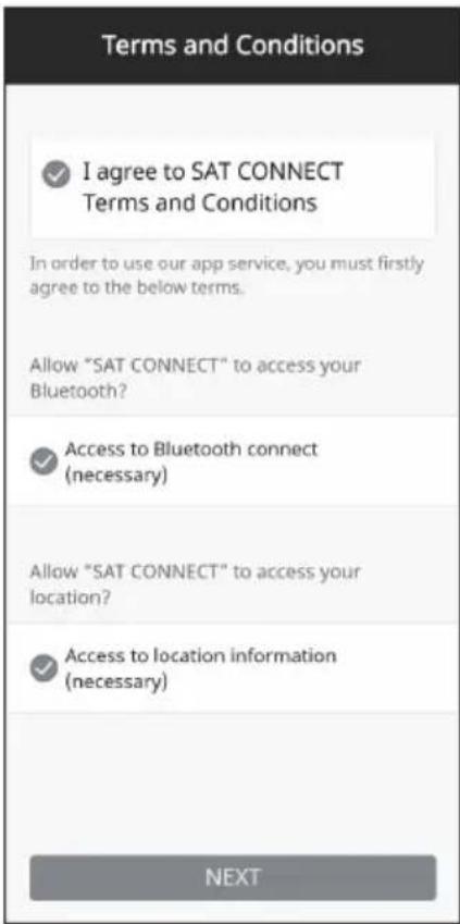
A. Download the app from the App Store (Android/iOS)
Search for SELFSAT on the App Store and download "SAT CONNECT" app
※ Before using this app, need to activate BT and GPS function on your smart device.
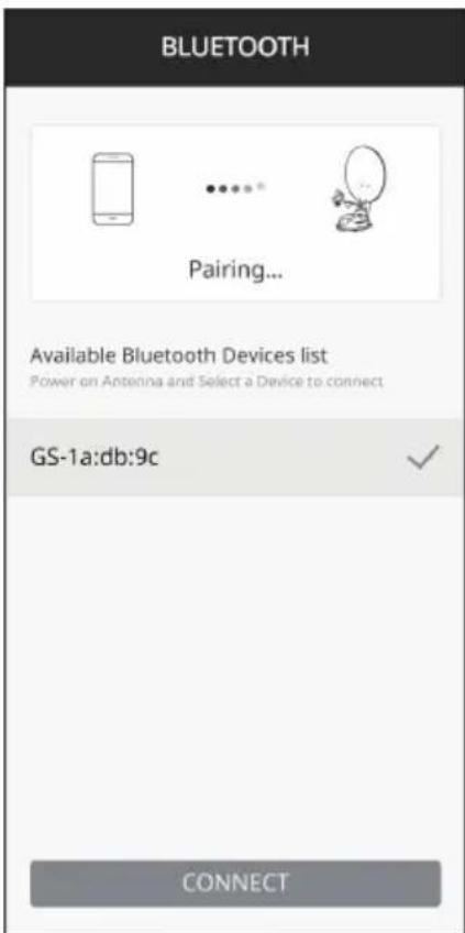
B. Pairing the antenna with App
step 1. Check the MAC Address at your antenna unit (on the antenna or PI box / User manual)
step 2. When you run the downloaded application, a connectable antenna unit is automatically detected
step 3. Select the one that matches your antenna MAC Address (The MAC address of CARAVAN PLUS is GS-xx:xx:xx)
step 4. Click the 'connect' button to complete BT connection between your antenna unit and smart device
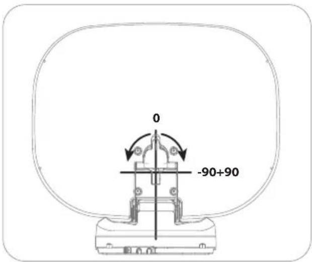
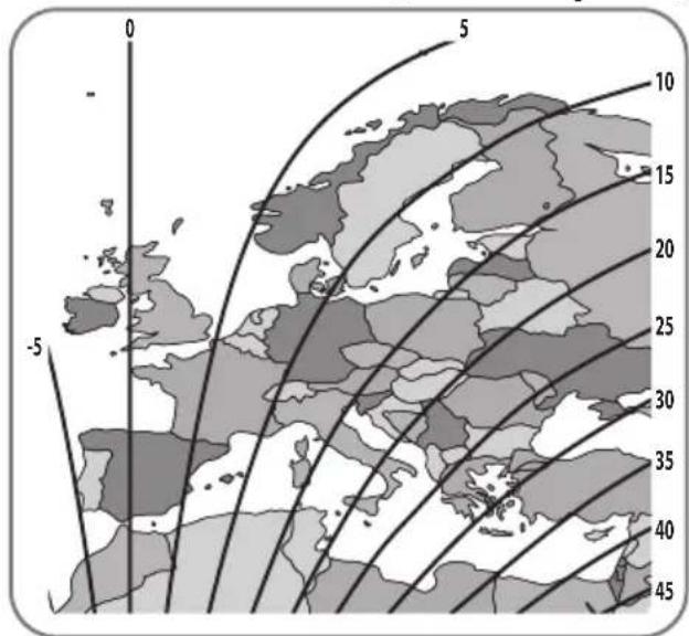
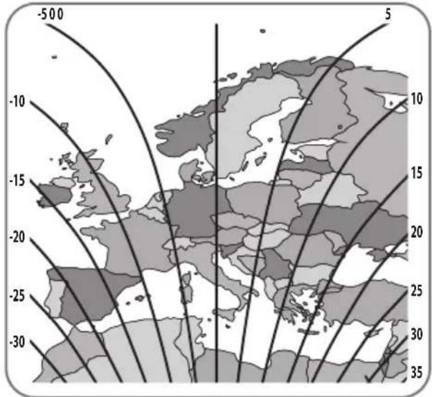
3. Skew adjustment
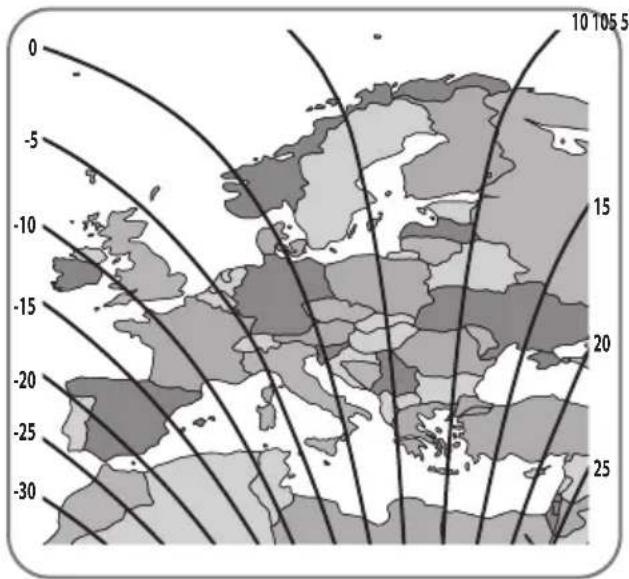
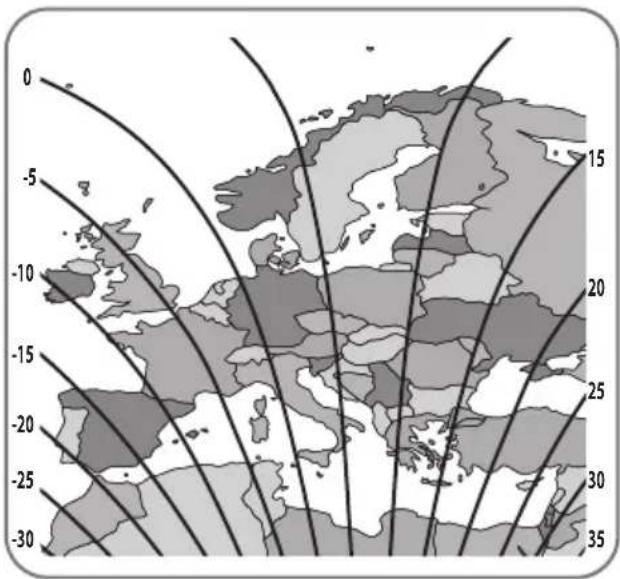
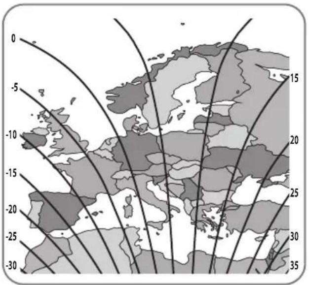
All LNBs require their rotational angle (skew) to be set within certain limits in order to the best signal quality received. The actual "skew angle" depends on the satellite and your location. Refer to the satellites you want to receive and your location in the image below and adjust the skew accordingly.
Accuracy is not critical, so small tolerances are acceptable. Turning the LNB little by little to find the position that maximizes the signal quality of the satellites on your TV screen, and then fix the LNB.
Turksat @ 42.0°E Astra2 @ 28.2°E
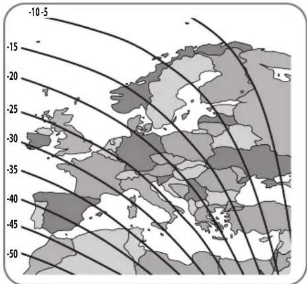
Astra3 @ 23.5°E Astra1 @ 19.2°E

HotBird @ 13.0°E Eutelsat 9 @ 9.0°E

line
| Latitude | Longitude | Value | | :--- | :--- | :--- | | -500 | -10 | 10 | | -500 | -15 | 15 | | -500 | -20 | 20 | | -500 | -25 | 25 | | -500 | -30 | 30 | | -500 | -35 | 35 | The chart displays a grayscale map of Europe with contour lines indicating direction along the latitude and longitude axes.
Astra4 @ 4.9°E Thor @ 0.8°W
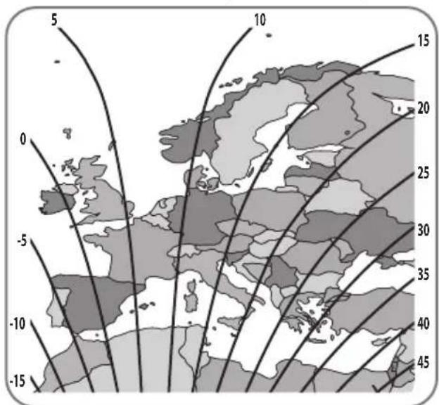

Eutelsat 5W @ 5.0°W Hispasat @ 30.0°W

4. Troubleshooting
There are a number of common issues that can affect the signal reception quality or the operation of the unit. The following sections address these issues and potential solutions.
A. No function when power on the antenna
i. Check again all the cable connections have been made correctly.
- Connection between the power and the PI box.
- Connection between the PI box and antenna.
ii. Check if the power input cable has been damaged.
iii. Check that the POWER input cable and the battery polarities(+/-) are connected correctly.
iv. Check if the PI Box is powered on (Check Power LED of PI BOX is on)
B. Fail to search the satellite
i. Satellite signals can be blocked or degraded by buildings, trees.
Make sure there are no obstructions in a southward direction.
ii. Turn the PI BOX off and then back on again.
C. Mechanical problems
i. If the antenna does not move into desired position.
- Try to power OFF/ON again.
ii. If the antenna makes a noise whilst remaining static.
- Try to power OFF/ON again. If problem persists, please contact local dealer/shop for assistance.
D. Other issues
i. If the system has been improperly wired, it will not operate properly.
Contact local dealer/shop for assistance of cable damage.
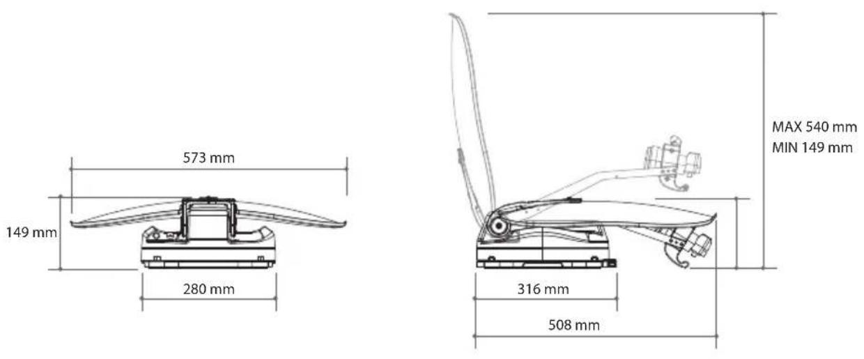
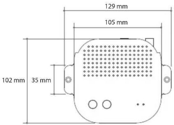
5. Specifications
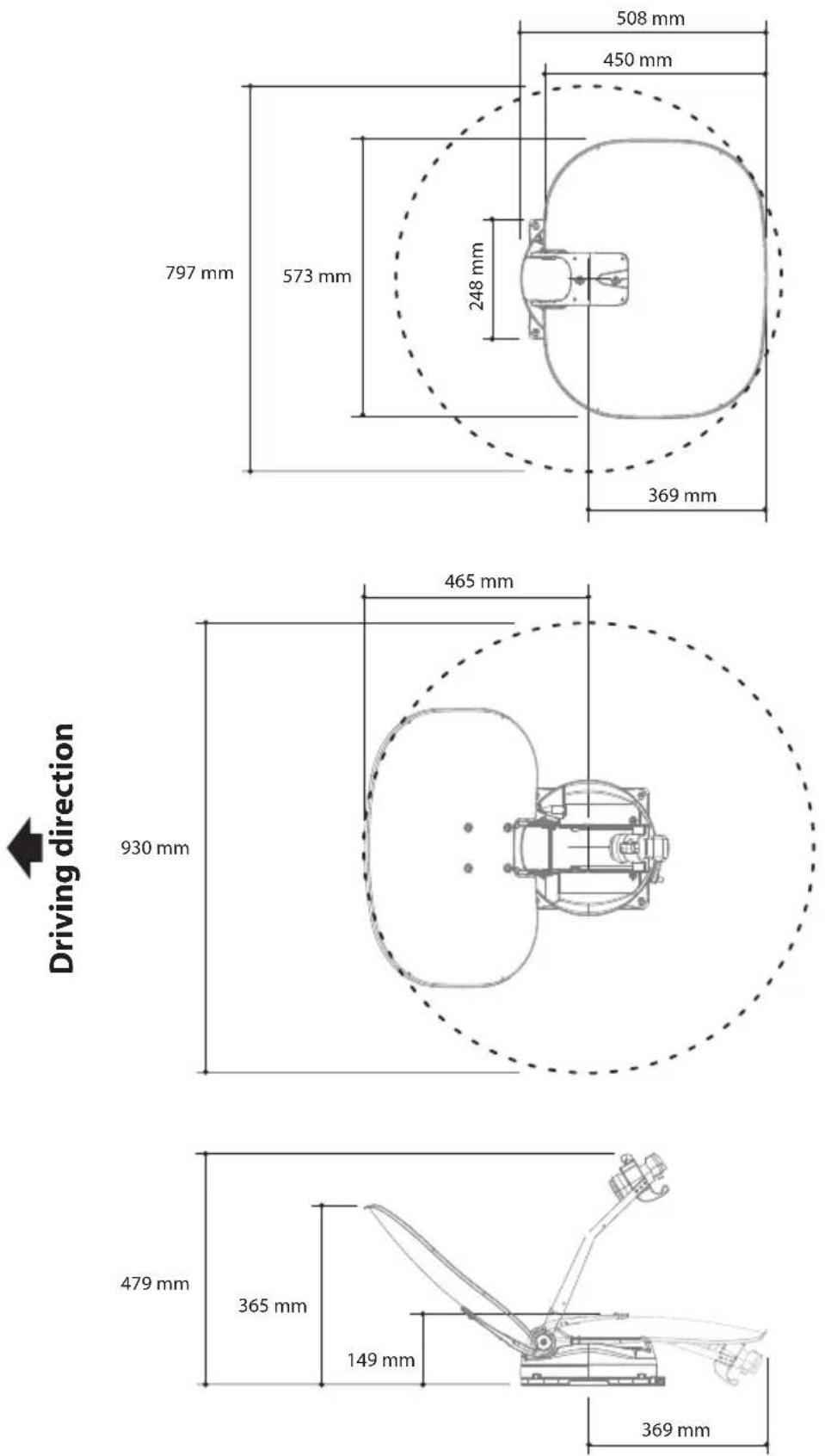
5-1. Dimension
Main Unit
PI box
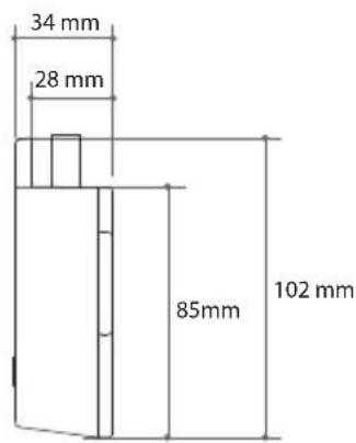
5-2. Specifications
| Model | CARAVAN PLUS | |
| Input Frequency | 10.7 ~ 12.75 GHz | |
| Polarization | Vertical & Horizontal | |
| Antenna Gain | 35.0 dBi @ 12.7 GHz | |
| Dish Size (W x D) | 573 mm x 450 mm (with edge) | |
| Size (W x D x H) | 573 x 508 x 149 mm | |
| Weight | 5.5 kg | |
| LNB | Output | 1 or 2 (optional) |
| Output Frequency | 950 ~ 2,150 MHz | |
| L.O. Frequency | 9.75 / 10.6 GHz | |
| Input Voltage | DC 12 V | |
| Power Consumption | 11 W (normal) / 30W (max) | |
| 3.6 W (stand-by) | ||
6. Caravan/Motorhome Installation
6-1. Required space for installation
Take care, that there is enough space for the fold CARAVAN PLUS, just as for the operation range (cruising radius).
6-2. Equipment for installation
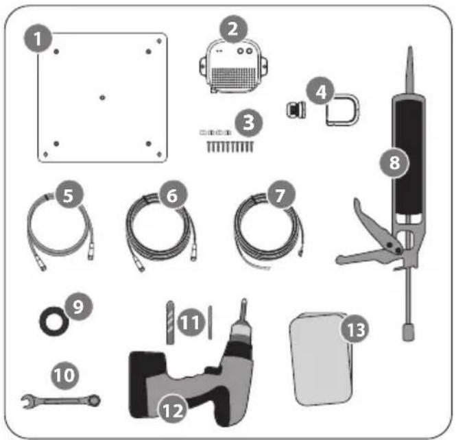
- Mounting plate
- PI BOX
- M4×20 screw (10), M8 locking nut (4)
- Cable gland / Cable holder
- PI cable
- Signal cable (x2 for twin output)
- Power input cable
- Silicone
- Masking tape
- Spanner
- 2mm drill bit, 16mm drill bit
- Power drill
- Cleaner
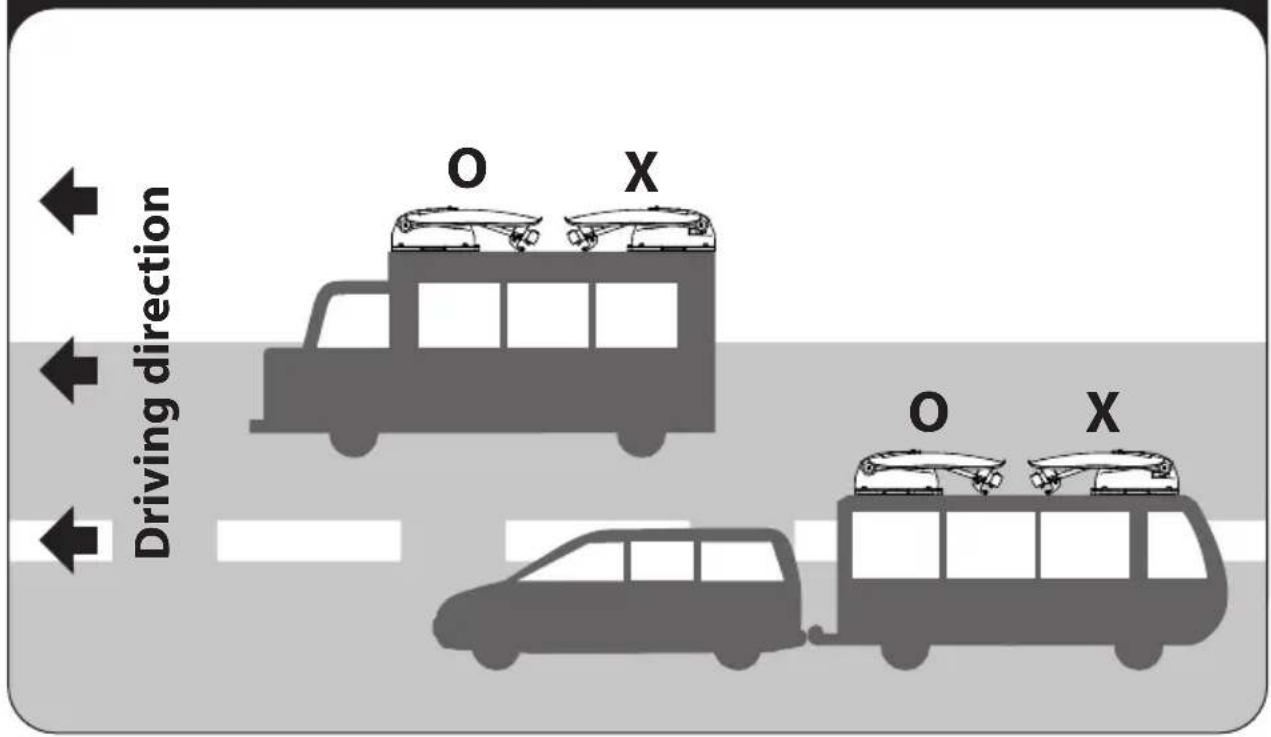
Installation of direction
6-3. Instruction for installation
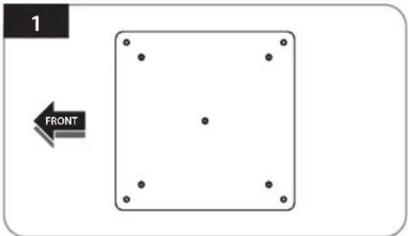
Locate a suitable location to place the mounting plate on the vehicle roof
natural_image
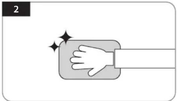
Illustration of a hand pressing down on a rectangular object with sparkles, no text or symbols presentClean the surface where will place the mounting plate with a cleaner
natural_image
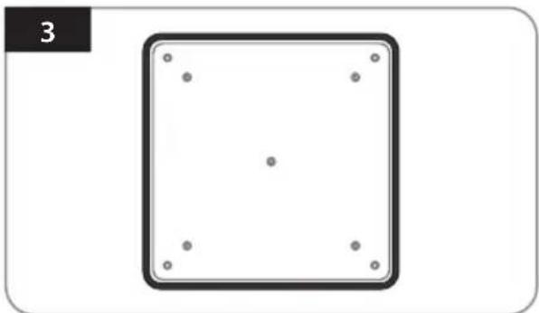
Simple diagram of a square with four dots at the center and four surrounding dots, no text or symbols present.Attach masking tape outside of the mounting plate by 5mm away from the plate edges
natural_image
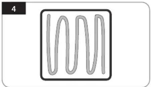
Simple line drawing of a wavy, three-peaked shape inside a square frame (no text or symbols)Put aside the mounting plate to apply silicone within the attached tape line but leave 2cm inward gap from the line
natural_image
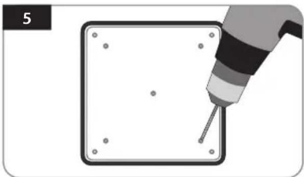
Illustration of a hand using a screwdriver to draw a square object with dots, no text or symbols presentPlace the mounting plate on the silicone and make 5 holes (2mm) with a power drill
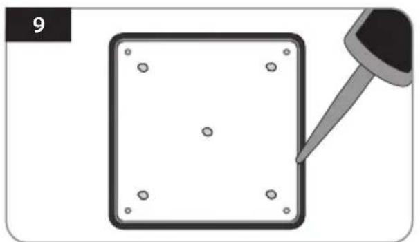
natural_image
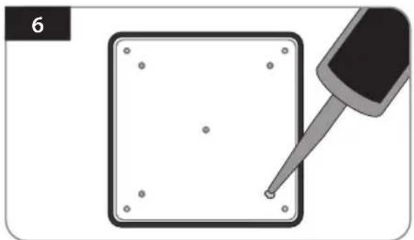
Illustration of a pipette tiping a square component with dots, no text or symbols presentApply silicone on the holes
natural_image
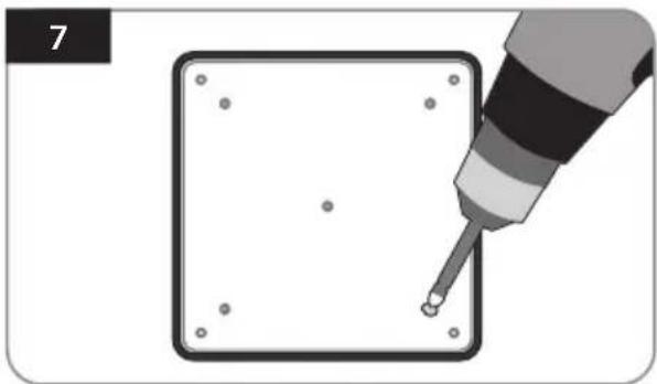
Illustration of a screwdriver inserted into a square component with holes, no text or symbols presentFix with five(5) of M4 x 20 screws on holes made
natural_image
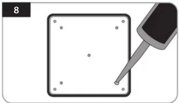
Illustration of a screwdriver touching a square component with holes, no text or symbols presentRe-apply silicone to cover screwed bolts
natural_image
Illustration of a square object with four small dots and a dropper tip, no text or symbols presentApply silicone around mounting plate edge
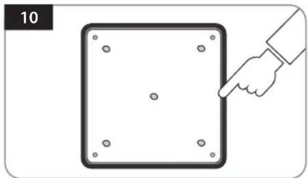
natural_image
Illustration of a hand pointing at a square panel with dots, labeled '10' (no text or symbols on the diagram itself)Clean away the excess silicone
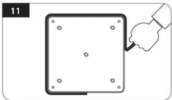
natural_image
Illustration of a hand holding a tool next to a square panel with holes, no text or symbols presentRemove masking tape and allow to dry
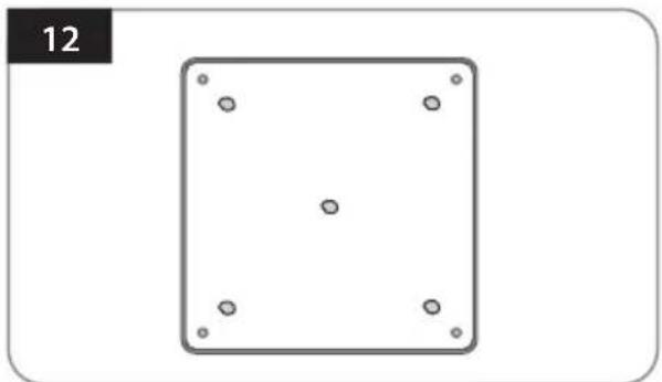
natural_image
Simple geometric diagram of a square with four corner dots and a label '12' in the top-left corner (no text or symbols within the diagram itself)Prepare to place the antenna on to the four upright bolts
natural_image
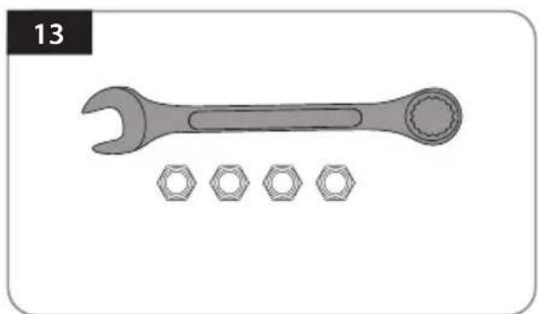
Illustration of a wrench and four bolts (no text or symbols)Parts required, spanner, four(4) nuts
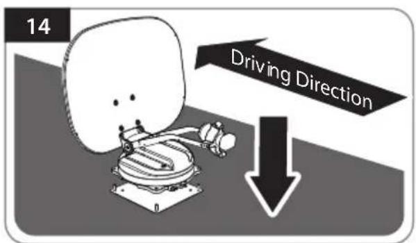
After checking the driving direction, place the antenna on the mounting plate
natural_image
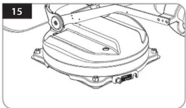
Technical line drawing of a mechanical assembly with no visible text or symbolsFit the nuts on each of the 4 bolts on the mounting plate
natural_image
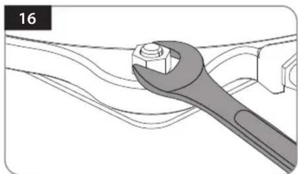
Illustration of a wrench turning a bolt on a mechanical component (no text or symbols)Tighten the four nuts with a spanner to secure the antenna
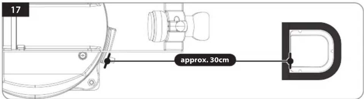
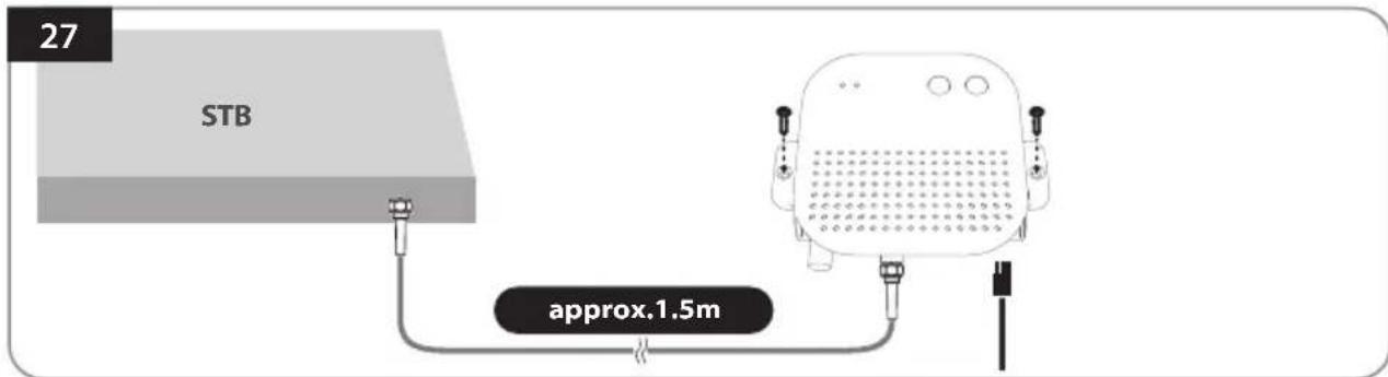
Connect the signal cable to the antenna port, place the bottom of the cable holder in a position that does not interfere with the operation of the antenna, and apply masking tape 5 mm from the outside of the bottom of the cable holder
natural_image
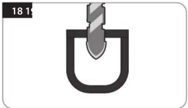
Simple diagram of a U-shaped object with a diagonal bar inserted into it, no text or symbols present.Drill a hole that the minimum size for the cable can pass through in the center of the tape marking (16mm or less)
natural_image
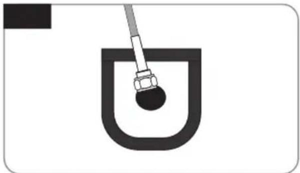
Simple line drawing of a U-shaped container with a rod inserted, no text or symbols presentPass the signal cable through the hole (two cables for twin output)
natural_image
Technical line drawing of a mechanical assembly with no visible text or symbolsInsert the signal cable, cable holder, and cable gland as shown in the picture above, and assemble it into the cable gland.
natural_image
Illustration of a hand using a tool to lift a U-shaped pipe or container (no text or symbols visible)Place the assembled cable holder inside the tape marking and drill three(3) of 2mm holes
natural_image
Diagram of a U-shaped container with a piping bag inserted, no text or symbols presentFix cable holder with three(3) of M4 x 20 screws on drill holes made
natural_image
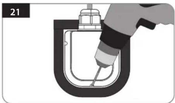
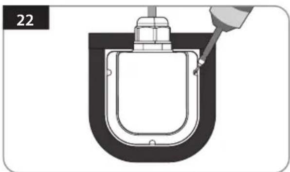
Diagram of a mechanical component being inserted into a U-shaped housing, with no visible text or symbolsApply silicone around cable holder and on the top of screws for waterproof
natural_image
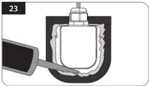
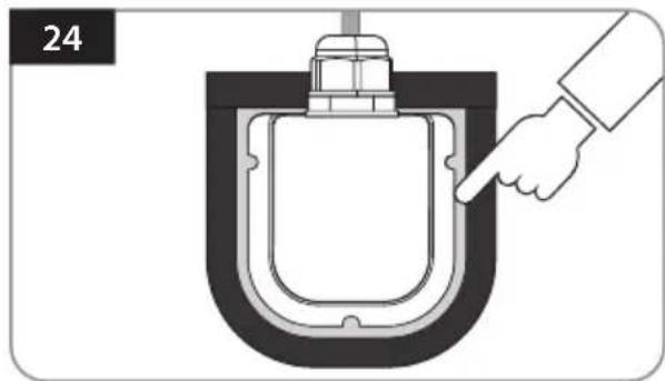
Diagram of a hand pressing a component into a U-shaped container (no text or symbols)Connect cables to the ports of the antenna, remove masking tape and tidy silicone before dry
natural_image
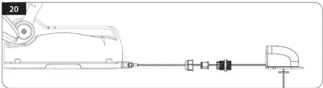
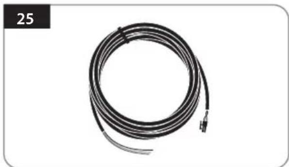
Coiled black cable with terminal connector, no visible text or symbolsPrepare the power input cable to connect the battery and PI BOX
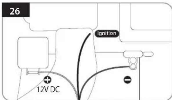
Match the power input cables polarities to the battery polarities, red to red / black to black and white cable to ignition port of vehicle
Fix the PI BOX in an appropriate place using two(2) M4x20 screws, and connect the power cable and PI cable
Inhaltsverzeichnis
natural_image
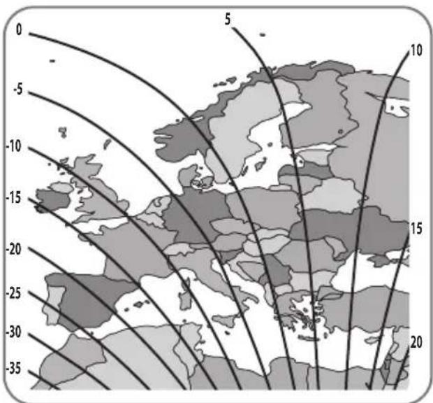
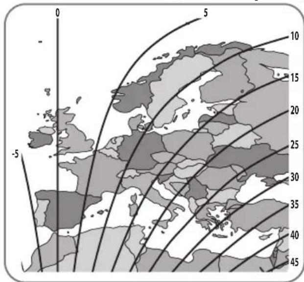
3D mechanical assembly diagram showing a component with an upward arrow indicating motion or force (no text or symbols present)Astra3 @ 23.5°E Astra1 @ 19.2°E
HotBird @ 13.0°E Eutelsat 9 @ 9.0°E

line
| Latitude | Longitude | Value | | -------- | --------- | ----- | | -50 | 5 | 10 | | -10 | 5 | 15 | | -15 | 5 | 20 | | -20 | 5 | 25 | | -25 | 5 | 30 | | -30 | 5 | 35 |
Astra4 @ 4.9°E Thor @ 0.8°W


Eutelsat 5W @ 5.0°W Hispasat @ 30.0°W

4. Fehlerbehebung
natural_image
Illustration of a hand pressing down on a button with sparkles (no text or symbols)natural_image
Simple geometric diagram of a square with four corner dots and a label '3' in the top-left corner (no text or symbols within the shape)natural_image
Simple line drawing of a wavy, coiled object inside a square frame (no text or symbols)natural_image
Illustration of a hand using a screwdriver to draw a square component (no text or symbols)natural_image
Illustration of a screwdriver tiping a square component with holes, no text or symbols presentnatural_image
Illustration of a screwdriver inserted into a square component with holes, no text or symbols presentnatural_image
Illustration of a dropper tip touching a square object with dots, no text or symbols presentnatural_image
Illustration of a dropper tiping a square object with holes, no text or symbols presentnatural_image
Illustration of a hand pointing at a square panel with four small dots, labeled '10' in the corner (no text or symbols on the diagram itself)natural_image
Illustration of a hand holding a tool near a square plate with holes, no text or symbols presentnatural_image
Simple geometric diagram of a square with four corner dots and a number 12 in the top-left corner (no text or symbols within the diagram itself)natural_image
Illustration of a wrench and four bolts (no text or symbols)natural_image
Technical line drawing of a mechanical assembly with no visible text or symbolsnatural_image
Illustration of a wrench turning a bolt on a mechanical component (no text or symbols)natural_image
Simple diagram of a U-shaped tool inserted into a slot, no text or symbols presentnatural_image
Simple line drawing of a U-shaped container with a rod inserted, no text or symbols presentnatural_image
Technical line drawing of a mechanical assembly with no visible text or symbolsnatural_image
Illustration of a hand using a tool to lift a U-shaped pipe or container (no text or symbols visible)natural_image
Diagram of a U-shaped container with a pipette inserted, no text or symbols presentnatural_image
Diagram of a mechanical component with a tool inserted into a U-shaped housing (no text or symbols)natural_image
Diagram of a hand pressing a component into a U-shaped container (no text or symbols)natural_image
Coiled black cable with terminal connector, no visible text or symbolsnatural_image
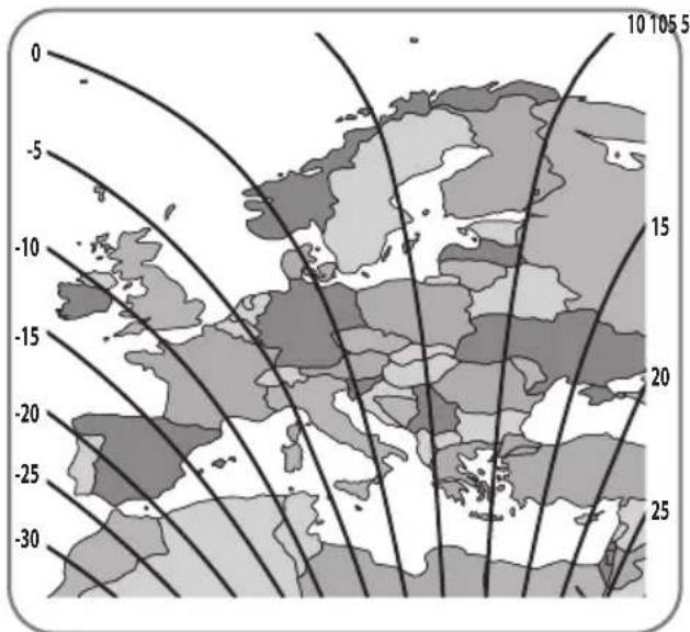
3D mechanical component diagram showing a housing with an upward arrow indicating motion or force (no text or symbols)Astra3 @ 23.5°E Astra1 @ 19.2°E
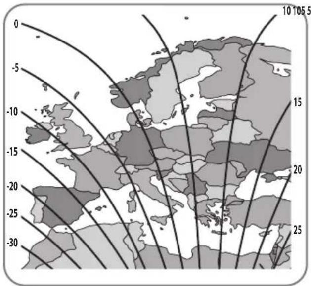
HotBird @ 13.0°E Eutelsat 9 @ 9.0°E
line
| Longitude | Latitude | Value | |---|---|---| | -500 | -10 | -10 | | -500 | -15 | -15 | | -500 | -20 | -20 | | -500 | -25 | -25 | | -500 | -30 | -30 | | -500 | -35 | -35 | | 5 | 5 | 5 | | 5 | 10 | 10 | | 5 | 15 | 15 | | 5 | 20 | 20 | | 5 | 25 | 25 | | 5 | 30 | 30 | | 5 | 35 | 35 |
Astra4 @ 4.9°E Thor @ 0.8°W


Eutelsat 5W @ 5.0°W Hispasat @ 30.0°W