
KC100.9 - String Trimmer KRESS - Free user manual and instructions
Find the device manual for free KC100.9 KRESS in PDF.

| Product Type | Cordless String Trimmer |
| Brand | Kress |
| Model | KC100.9 (KC100, KC100.X) |
| Rated Voltage | 60 V max (54 V nominal) |
| Cutting Speed | 4200 / 5100 / 5900 rpm (3 levels) |
| Cutting Diameter | 42 cm (16.5") |
| Line Diameter | 2.4 / 2.7 mm (nylon) |
| Weight (tool only) | 4.5 kg (9.9 lb) |
| Protection Rating | IPX4 |
| Battery Type | Li-Ion, 60 V, compatible with KAC804 (4.0 Ah) or KAC810 (11.0 Ah with back harness) |
| Recommended Charger | KAC840 (30 A) or KAC810 back harness charger |
| Sound Pressure Level (LpA) | 79.7 dB(A) (K=3 dB(A)) |
| Sound Power Level (LwA) | 94.94 dB(A) (K=0.59 dB(A)) |
| Vibration (ah) | 2.45 m/s² (K=3 m/s²) |
| Line Feed System | Semi-automatic bump feed |
| Safety Features | Operator presence button, on/off switch, overload, temperature and low battery protection |
| Periodic Maintenance | Lubricate gearbox and clean air filter every 50 hours |
| Transport | Battery removed, hold by the center of the shaft, cutting head at the rear |
| Storage | Dry and secure place, battery between 5 °C and 25 °C |
| Compatible Accessories | 4" and 5" cutting heads, deflectors, knife blade (with universal deflector), shoulder strap, back harness |
| Intended Use | Cutting grass, tall weeds, edges, sloped areas inaccessible to lawnmowers |
Frequently Asked Questions - KC100.9 KRESS
User questions about KC100.9 KRESS
0 question about this device. Answer the ones you know or ask your own.
Ask a new question about this device
Download the instructions for your String Trimmer in PDF format for free! Find your manual KC100.9 - KRESS and take your electronic device back in hand. On this page are published all the documents necessary for the use of your device. KC100.9 by KRESS.
USER MANUAL KC100.9 KRESS
natural_image
Black handheld device with attached sensor and connector (no visible text or symbols)| Cordless Grass Trimmer | EN | P03 |
| Kabelloser Rasentrimmer | D | P18 |
| Coupe-bordure sans fil | F | P34 |
| Decespugliatore senza fili | I | P49 |
| Cortabordes a batería | ES | P64 |
| Aparador de relva sem fio | PT | P79 |
| Snoerloze grastrimmer | NL | P94 |
| Akkumulátoros szegélynyíró | HU | P109 |
| Motocoasă fără fir | RO | P125 |
| Bezprzewodowa podkaszarka do trawy | PL | P140 |
| Bezdrátová strunová sekačka na trávu | CZ | P155 |
| Akumulátorová kosačka na trávu | SK | P170 |
| Brezžični obrezovalnik trave | SL | P185 |
| Akumulatorski trimer za travu | HR | P200 |
| Ledningsfri græstrimmer | DK | P214 |
| Akkukäyttöinen ruohotrimmeri | FIN | P228 |
| Trådløs gresstrimmer | NOR | P242 |
| Sladdløs grästrimmer | SV | P256 |
KC100 KC100.X
TABLE OF CONTENTS
Introduction....3
Component List....4
Product Safety....5
Assembly & Operation....9
Transportation....11
Maintenance....12
Cleaning....13
Storage....13
Troubleshooting....14
Technical Data....15
Environmental Protection....16
Declaration of Conformity....16
INTRODUCTION
Dear Customer,
Thank you for buying this Kress Commercial product. We are dedicated to developing high quality products to meet your commercial landscaping requirements.
The Kress brand is synonymous with premium quality service. Over the years of your product's life, if you have any questions or concerns about your product, please contact your dealer or our Customer Service Team for assistance.
We are confident you will enjoy working with your Kress product for years to come.
INTENDED USE
This machine is intended for cutting grass and high weeds that cannot be reached with a lawn mower. This machine is also used on areas with slopes not conducive to mowing.
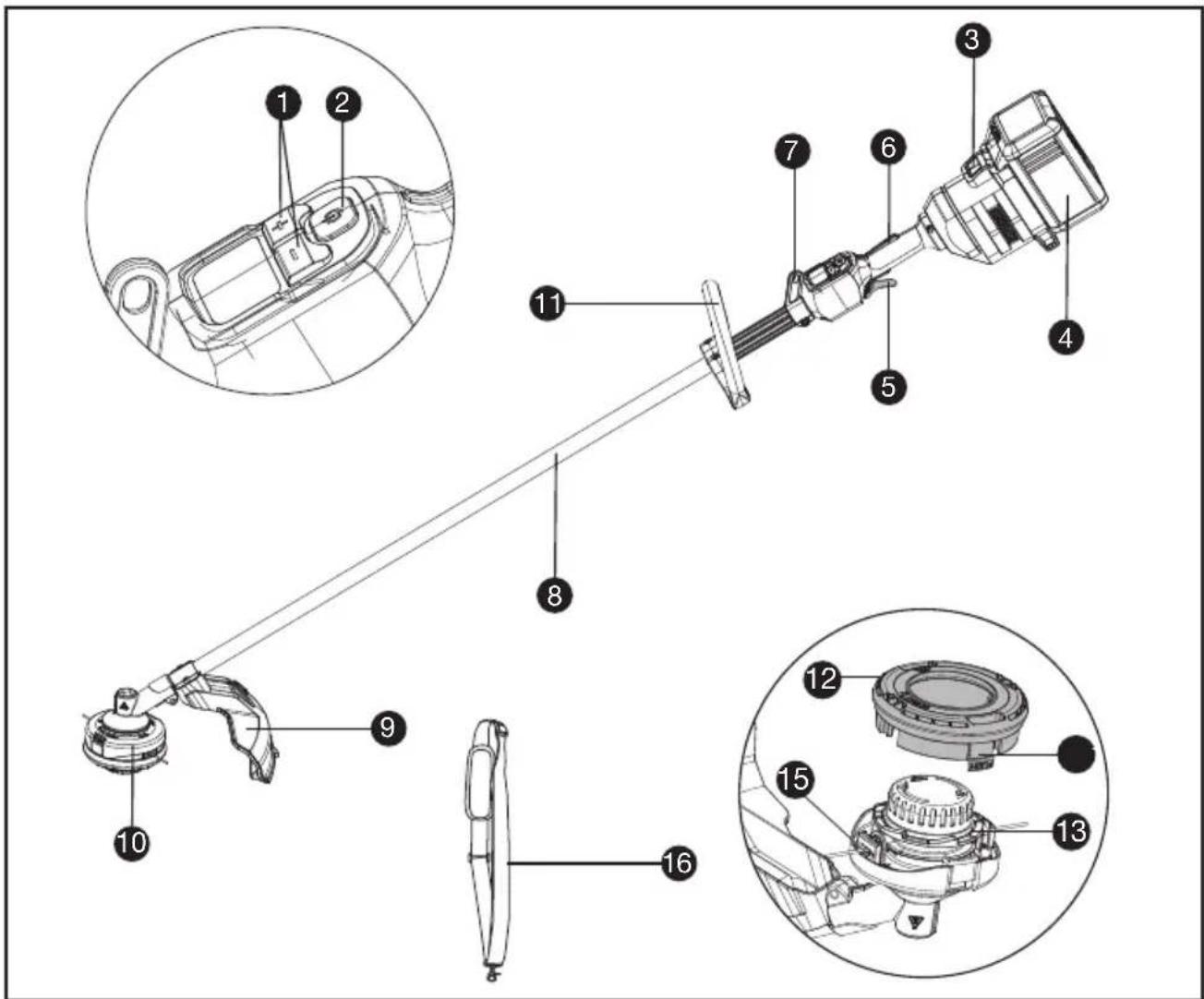
COMPONENT LIST
- SPEED CONTROL
- ON / OFF SWITCH
- BATTERY PACK RELEASE
- BATTERY PACK *
- THROTTLE TRIGGER
- OPERATOR PRESENCE SWITCH
- SHOULDER STRAP MOUNT
- SHAFT
- DEBRIS GUARD
- TRIMMER HEAD
- FRONT HANDLE
- SPOOL CAP
- SPOOL
- CAP RELEASE LATCH
- EYELET
- SHOULDER STRAP *
ORIGINAL INSTRUCTIONS PRODUCT SAFETY GENERAL POWER TOOL SAFETY WARNINGS

WARNING Read all safety warnings, instructions, illustrations and specifications
provided with this power tool. Failure to follow all instructions listed below may result in electric shock, fire and/or serious injury.
Save all warnings and instructions for future reference.
The term "power tool" in the warnings refers to your mains-operated (corded) power tool or battery-operated (cordless) power tool.
1) Work area safety
a) Keep work area clean and well lit. Cluttered or dark areas invite accidents.
b) Do not operate power tools in explosive atmospheres, such as in the presence of flammable liquids, gases or dust. Power tools create sparks which may ignite the dust or fumes.
c) Keep children and bystanders away while operating a power tool. Distractions can cause you to lose control.
2) Electrical safety
a) Power tool plugs must match the outlet. Never modify the plug in any way. Do not use any adapter plugs with earthed (grounded) power tools. Unmodified plugs and matching outlets will reduce risk of electric shock.
b) Avoid body contact with earthed or grounded surfaces, such as pipes, radiators, ranges and refrigerators. There is an increased risk of electric shock if your body is earthed or grounded.
c) Do not operate the machine in rain or wet conditions. This may increase the risk of electric shock. Once got wet in the rain during operation, the machine and the battery should be dried before storing or charging. Remove the battery and reinsert it if the machine fails to turn on. Keep battery connection free of dirt and debris, and clean with a soft and dry brush or cloth.
d) Do not abuse the cord. Never use the cord for carrying, pulling or unplugging the power tool. Keep cord away from heat, oil, sharp edges or moving parts. Damaged or entangled cords increase the risk of electric shock.
e) When operating a power tool outdoors, use an extension cord suitable for outdoor use. Use of a cord suitable for outdoor use reduces the risk of electric shock.
f) If operating a power tool in a damp location is unavoidable, use a residual current device (RCD) protected supply. Use of an RCD reduces the risk of electric shock.
3) Personal safety
a) Stay alert, watch what you are doing and use common sense when operating a power tool. Do not use a power tool while you are tired or under the influence of drugs, alcohol or medication. A moment of inattention while operating power tools may result in serious personal injury.
b) Use personal protective equipment. Always wear eye protection. Protective equipment such as dust mask, non-skid safety shoes, hard hat, or hearing protection used for appropriate conditions will reduce personal injuries.
c) Prevent unintentional starting. Ensure the switch is in the off-position before connecting to power source and/or battery pack, picking up or carrying the tool. Carrying power tools with your finger on the switch or energising power tools that have the switch on invites accidents.
d) Remove any adjusting key or wrench before turning the power tool on. A wrench or a key left attached to a rotating part of the power tool may result in personal injury.
e) Do not overreach. Keep proper footing and balance at all times. This enables better control of the power tool in unexpected situations.
f) Dress properly. Do not wear loose clothing or jewellery. Keep your hair and clothing away from moving parts. Loose clothes, jewellery or long hair can be caught in moving parts.
g) If devices are provided for the connection of dust extraction and collection facilities, ensure these are connected and properly used. Use of dust collection can reduce dust-related hazards.
h) Do not let familiarity gained from frequent use of tools allow you to become complacent and ignore tool safety principles. A careless action can cause severe injury within a fraction of a second.
4) Power tool use and care
a) Do not force the power tool. Use the correct power tool for your application. The correct power tool will do the job better and safer at the rate for which it was designed.
b) Do not use the power tool if the switch does not turn it on and off. Any power tool that cannot be controlled with the switch is dangerous and must be repaired.
c) Disconnect the plug from the power source and/or remove the battery pack, if detachable, from the power tool before making any adjustments, changing accessories, or storing power tools. Such preventive safety measures reduce the risk of starting the power tool accidentally.
d) Store idle power tools out of the reach of children and do not allow persons unfamiliar with the power tool or these instructions to operate the power tool. Power tools are dangerous in the hands of untrained users.
e) Maintain power tools and accessories. Check for misalignment or binding of moving parts, breakage of parts and any other condition that may affect the power tool's operation.
If damaged, have the power tool repaired before use. Many accidents are caused by poorly maintained power tools.
f) Keep cutting tools sharp and clean. Properly maintained cutting tools with sharp cutting edges are less likely to bind and are easier to control.
g) Use the power tool, accessories and tool bits etc. in accordance with these instructions, taking into account the working conditions and the work to be performed. Use of the power tool for operations different from those intended could result in a hazardous situation.
h) Keep handles and grasping surfaces dry, clean and free from oil and grease. Slippery handles and grasping surfaces do not allow for safe handling and control of the tool in unexpected situations.
5) Battery tool use and care
a) Recharge only with the charger specified by the manufacturer. A charger that is suitable for one type of battery pack may create a risk of fire when used with another battery pack.
b) Use power tools only with specifically designated battery packs. Use of any other battery packs may create a risk of injury and fire.
c) When battery pack is not in use, keep it away from other metal objects, like paper clips, coins, keys, nails, screws or other small metal objects, that can make a connection from one terminal to another. Shorting the battery terminals together may cause burns or a fire.
d) Under abusive conditions, liquid may be ejected from the battery; avoid contact. If contact accidentally occurs, flush with water. If liquid contacts eyes, additionally seek medical help. Liquid ejected from the battery may cause irritation or burns.
e) Do not use a battery pack or tool that is damaged or modified. Damaged or modified batteries may exhibit unpredictable behaviour resulting in fire, explosion or risk of injury.
f) Do not expose a battery pack or tool to fire or excessive temperature. Exposure to fire or temperature above 130 °C may cause explosion.
g) Follow all charging instructions and do not charge the battery pack or tool outside the temperature range specified in the instructions. Charging improperly or at temperatures outside the specified range may damage the battery and increase the risk of fire.
6) Service
a) Have your power tool serviced by a qualified repair person using only identical replacement parts. This will ensure that the safety of the power tool is maintained.
b) Never service damaged battery packs. Service of battery packs should only be performed by the manufacturer or authorized service providers.
BRUSH CUTTER AND BRUSH
SAW SAFETY WARNINGS
a) Do not use the machine in bad weather conditions, especially when there is a risk of lightning. This decreases the risk of being struck by lightning.
b) Thoroughly inspect the area for wildlife where the machine is to be used. Wildlife may be injured by the machine during operation.
c) Thoroughly inspect the area where the machine is to be used and remove all stones, sticks, wires, bones, and other foreign objects. Thrown objects can cause personal injury.
d) Before using the machine, always visually inspect to see that the cutter or blade and the cutter or blade assembly are not damaged. Damaged parts increase the risk of injury.
e) Follow instructions for changing accessories.
Improperly tightened blade securing nuts or bolts may either damage the blade or result in it becoming detached.
f) The rated rotational speed of the blade must be at least equal to the maximum rotational speed marked on the machine. Blades running faster than their rated rotational speed can break and fly apart.
g) Wear eye, ear, head and hand protection.
Adequate protective equipment will reduce personal injury by flying debris or accidental contact with the cutting line or blade.
h) While operating the machine, always wear safety footwear. Do not operate the machine when barefoot or wearing open sandals. This reduces the chance of injury to the feet from contact with a moving cutter, line or blade.
i) While operating the machine, always wear long trousers. Exposed skin increases the likelihood of injury from thrown objects.
j) Keep bystanders away while operating the machine. Thrown debris can result in serious personal injury.
k) Always use two hands when operating the machine. Holding the machine with both hands will avoid loss of control.
I) Hold the machine by the insulated gripping surfaces only, because the cutting line or blade may contact hidden wiring. Cutting line or blades contacting a "live" wire may make exposed metal parts of the machine "live" and could give the operator an electric shock.
m) Always keep proper footing and operate the machine only when standing on the ground. Slippery or unstable surfaces may cause a loss of balance or control of the machine.
n) Do not operate the machine on excessively steep slopes. This reduces the risk of loss of control, slipping and falling which may result in personal injury.
o) When working on slopes, always be sure of your footing, always work across the face of slopes, never up or down and exercise extreme caution when changing direction. This reduces the risk of loss of control, slipping
and falling which may result in personal injury.
p) Keep all parts of the body away from the cutter, line or blade when the machine is operating. Before you start the machine, make sure the cutter, line or blade is not contacting anything. A moment of inattention while operating the machine may result in injury to yourself or others.
q) Do not operate the machine above waist height. This helps prevent unintended cutter or blade contact and enables better control of the machine in unexpected situations.
r) When cutting brush or saplings that are under tension, be alert for spring back. When the tension in the wood fibres is released, the brush or sapling may strike the operator and/or throw the machine out of control.
s) Use extreme caution when cutting brush and saplings. The slender material may catch the blade and be whipped toward you or pull you off balance.
t) Maintain control of the machine and do not touch cutters, lines or blades and other hazardous moving parts while they are still in motion. This reduces the risk of injury from moving parts.
u) Carry the machine with the machine switched off and away from your body.
Proper handling of the machine will reduce the likelihood of accidental contact with a moving cutter, line or blade.
v) When transporting or storing the machine, always fit the cover on metal blades. Proper handling of the machine will reduce the likelihood of accidental contact with the blade.
w) Only use replacement cutters, lines, cutting heads and blades specified by the manufacturer. Incorrect replacement parts may increase the risk of breakage and injury.
x) When clearing jammed material or servicing the machine, make sure the switch is off and the battery pack is removed. Unexpected starting of the machine while clearing jammed material or servicing may result in serious personal injury.
BLADE THRUST CAUSES AND RELATED WARNINGS
Blade thrust is a sudden sideways, forward or backward motion of the machine, which may occur when the blade jams or catches on an object such as a sapling or a tree stump. It can be violent enough to cause the machine and/or operator to be propelled in any direction, and possibly lose control of the machine.
Blade thrust and its related hazards can be avoided by taking proper precautions as given below.
a) Maintain a firm grip with both hands on the machine and position your arms to resist blade thrust. Position your body to the left side of the machine. Blade thrust can increase the risk of
injury due to the machine moving unexpectedly. Blade thrust can be controlled by the operator if proper precautions are taken.
b) If the blade binds, or when interrupting a cut for any reason, switch the machine off and hold the machine motionless in the material until the blade comes to a complete stop. While the blade is binding, never attempt to remove the machine from the material or pull the machine backward while the blade is in motion, otherwise blade thrust may occur. Investigate and take corrective actions to eliminate the cause of blade binding.
c) Do not use blunt or damaged blades. Blunt or damaged blades increase the risk of jamming or catching on an object, resulting in blade thrust.
d) Always maintain good visibility of the material being cut. Blade thrust is more likely to occur in areas where it is difficult to see the material being cut.
e) If you are approached by another person while operating the machine, switch the machine off. There is an increased risk of injury to other persons being struck by the moving blade in the event of blade thrust.
SAFETY WARNINGS FOR BATTERY PACK
a) Do not dismantle, open or shred cells or battery pack.
b) Do not short-circuit a battery pack. Do not store battery packs haphazardly in a box or drawer where they may short-circuit each other or be short-circuited by conductive materials. When battery pack is not in use, keep it away from other metal objects, like paper clips, coins, keys, nails, screws or other small metal objects, that can make a connection from one terminal to another. Shorting the battery terminals together may cause burns or a fire.
c) Do not expose battery pack to heat or fire. Avoid storage in direct sunlight.
d) Do not subject battery pack to mechanical shock.
e) In the event of battery leaking, do not allow the liquid to come into contact with the skin or eyes. If contact has been made, wash the affected area with copious amounts of water and seek medical advice.
f) Keep battery pack clean and dry.
g) Wipe the battery pack terminals with a clean dry cloth if they become dirty.
h) Battery pack needs to be charged before use. Always refer to this instruction and use the correct charging procedure.
i) Do not maintain battery pack on charge when not in use.
j) After extended periods of storage, it may be necessary to charge and discharge the battery pack several times to obtain
maximum performance.
k) Recharge only with the charger specified by Kress. Do not use any charger other than that specifically provided for use with the equipment.
I) Do not use any battery pack which is not designed for use with the equipment.
m) Keep battery pack out of the reach of children.
n) Retain the original product literature for future reference.
o) Remove the battery from the equipment when not in use.
p) Dispose of properly.
q) Do not mix cells of different manufacture, capacity, size or type within a device.
r) Keep the battery away from microwaves and high pressure.
USER MANUAL REQUIREMENTS FOR WIRELESS PRODUCT
a) Operation of this device is subject to the following two conditions:
(1) This device may not cause harmful interference, and
(2) this device must accept any interference received, including interference that may cause undesired operation.
b) Caution: Changes or modifications to this unit not expressly approved by the party responsible for compliance could void the user's authority to operate the equipment.
c) NOTE: This equipment generates, uses and can radiate radio frequency energy and, if not installed and used in accordance with the instructions, may cause harmful interference to radio communications. However, there is no guarantee that interference will not occur in a particular installation. If this equipment does cause harmful interference to radio or television reception, which can be determined by turning the equipment off and on, the user is encouraged to try to correct the interference by one or more of the following measures:
- Reorient or relocate the receiving antenna.
- Increase the separation between the equipment and receiver.
- Connect the equipment into an outlet on a circuit different from that to which the receiver is connected.
- Consult the dealer or an experienced radio/TV technician for help.
SYMBOLS

To reduce the risk of injury, user must read instruction manual


Wear eye, ear and head protection
Wear slip-resistant footwear
WARNING – The distance between the machine and bystanders shall be at least 15 m (50 ft)


WARNING – Beware of thrown objects.

WARNING – Beware of blade thrust
Do not use metal blades

WARNING – Disconnect battery before maintenance

Wear hand protection

Waste electrical products must not be disposed of with household waste. Please recycle where facilities exist. Check with your local authorities or retailer for recycling advice.

Li-Ion battery This product has been marked with a symbol relating to ‘separate collection’ for all battery packs and battery pack. It will then be recycled or dismantled in order to reduce the impact on the environment. Battery packs can be hazardous for the environment and for human health since they contain hazardous substances.

Do not burn
 | Batteries may enter water cycle if disposed improperly, which can be hazardous for ecosystem. Do not dispose of waste batteries as unsorted municipal waste. |
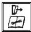
 | Make sure the battery is removed prior to changing accessories. |
 | Trimming |
NOTE: Before using the tool, read the instruction book carefully.

BEFORE OPERATION:
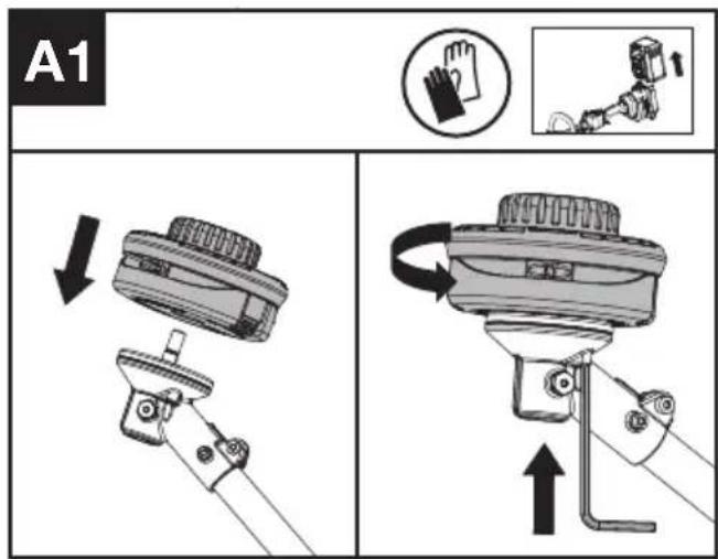
Assembling the cutting head (See Fig. A1)
Fit the cutting head. Insert the hex key into the hole and rotate the trimmer head counterclockwise until it stops in a locked position.
Assembling the debris guard (See Fig. A2)
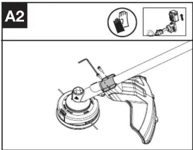
- Install the correct Debris Guard for the trimmer head.
- Secure the guard in place using the screw and torx key.
Assembling the Front Handle (See Fig. B)
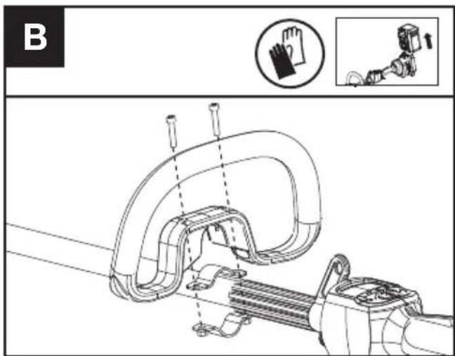
- Attach the Front Handle and lower clamp on the shaft.
- Put the bolt through the holes.
- Tighten the Front Handle.

WARNING: Adjust the Front Handle as desired so as to make sure your front arm is at when using the trimmer.
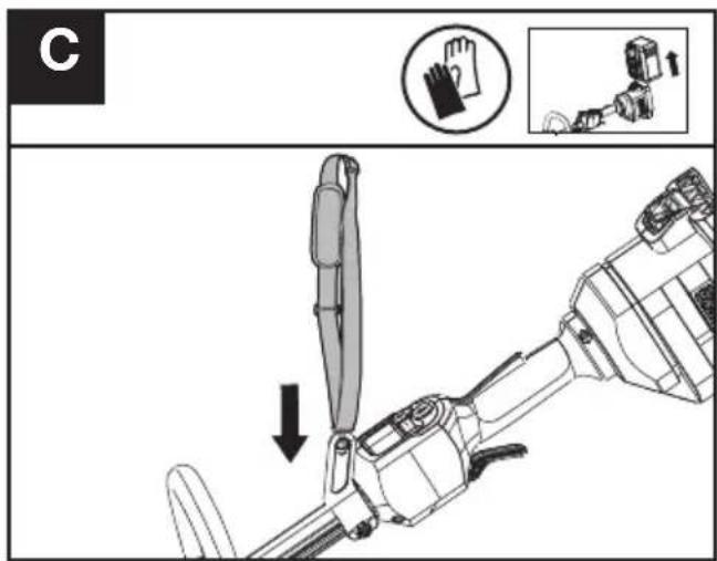
Fitting the shoulder strap (Sold Separately) (See Fig. C)
- Adjust the length of shoulder strap to make sure that the carabiner is about a hand's width below the top of your hip.
- Connect the carabiner of the accessory shoulder strap to the mounting point on the shaft of the trimmer.
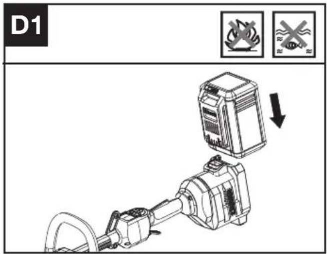
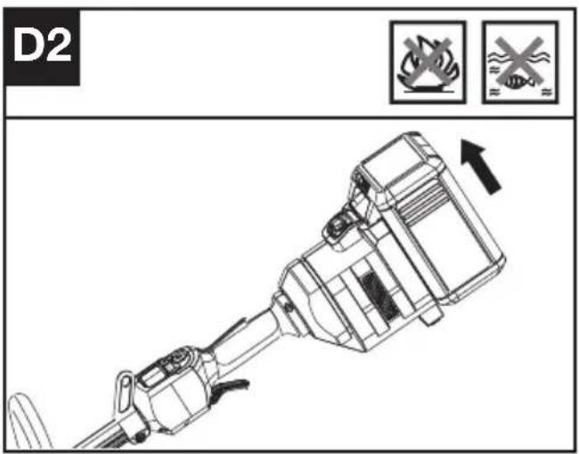
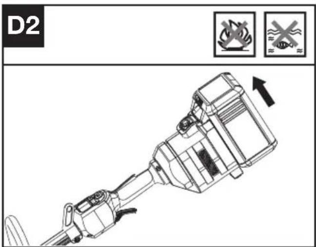
Installing & removing the battery pack (See Fig. D1, D2)
- Slide the battery pack into the battery compartment until you hear a click.
- Press the battery pack release to release battery pack from your tool.
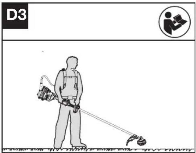
Connecting with the backpack harness (See Fig. D3)
The trimmer can be connected with an accessory backpack harness (not supplied). Refer to the backpack harness manual for more information.
TESTING THE TRIMMER AND BATTERY (See Fig. E)
Checking the controls Operator Presence Switch and Throttle Trigger
- Remove the battery.
- Try to press the Throttle Trigger. If the Throttle Trigger can be pressed without depressing
the Operator Presence Switch, the Operator Presence Switch is defective. Stop using the trimmer and contact the service agent.
- Hold and press the Operator Presence Switch first, then press the Throttle Trigger.
- Release the Throttle Trigger and the Operator Presence Switch. If the Throttle Trigger or the Operator Presence Switch is stuck and cannot spring back to its original position. Stop using the trimmer and contact the service agent.
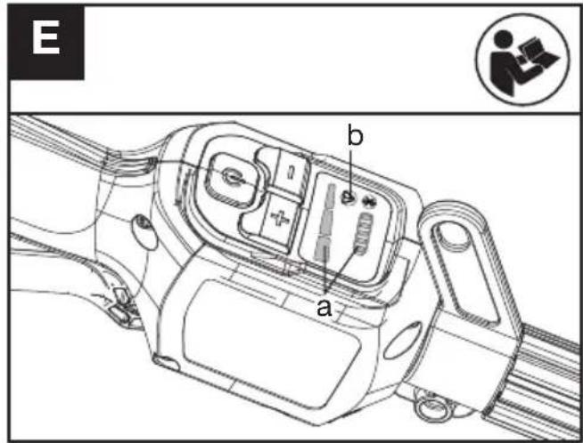
Checking the display
- Insert the battery.
- Hold and press the On / Off Switch.
The product is switched on when the LED (a) is lit.
The product is switched off when the LED (a) is out.
- Press the Operator Presence Switch first, then press the Throttle Trigger to start the machine. The Trimmer Head rotates.
- If the warning indicator (b) lights up or is flashing, refer to Troubleshooting for solutions.
- Release the Throttle Trigger. The Trimmer Head stops rotating after a short delay. If the Trimmer Head continues to rotate, remove the battery and contact the service agent.
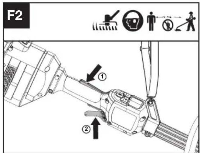
OPERATION: Starting the trimmer (See Fig. F1, F2)
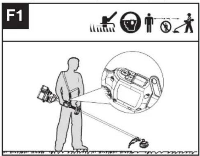
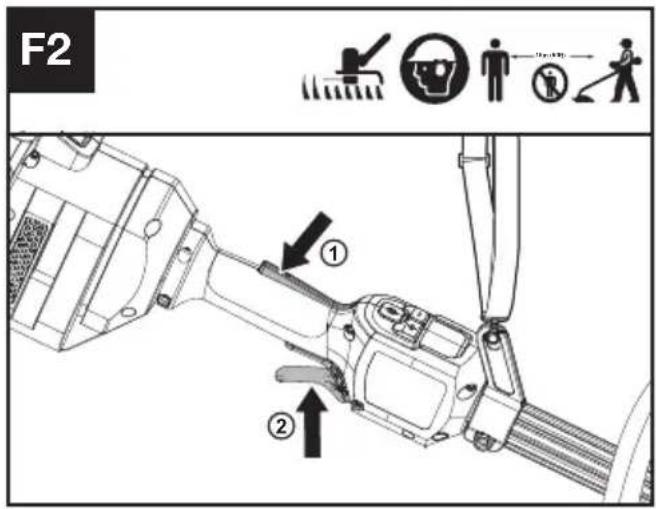
- Hold the trimmer firmly with your right hand on the control handle – wrap your thumb around the handle. Hold the trimmer with your left hand on the auxiliary handle– wrap your thumb around the handle.
- Hold and press the On / Off Switch until the green LED is lit. The green LED shows the power level.
- Press the Operator Presence Switch first, then press the Throttle Trigger to start the machine. The green LED for start/stop goes off after 5 seconds if not being used as a safety procedure. When not cutting, the unit will remain on if the operator presence switch is held down without operating the machine. If the green LED goes out, the product will need to be restarted.
NOTE: The Operator Presence Switch is designed to prevent accidental operation. When you press the Operator Presence Switch it releases the Throttle Trigger.
Selecting the speed
3 Power Levels can be selected depending on the application. Use the +/- to control the speed, which is as indicated by the LEDs. The higher the power level, the faster the tool runs.
Stopping the trimmer
Release the Throttle Trigger to stop the machine.

WARNING! The cutting head continues to rotate after the trimmer has been switched off; wait until it has completely stopped then lay down the tool.
Bump-line feed system (See Fig. G)
The trimmer is equipped with a bump-line system. Just bump the trimmer head while the machine is running, new line will feed out.

Cutting Tips (See Fig. H)

- Swing the trimmer from side to side across the area to be cut.
- Use the tip of the cutting line to do trimming; do not force the trimmer head into uncut grass.
- Wire and picket fences may cause extra cutting line wear and breakage. Stone and brick walls, curbs, and wood may wear cutting line rapidly.
- Avoid trees and shrubs. Tree bark, wood moldings, siding, and fence posts can easily be damaged by the cutting line.
- The selected power level affects the battery's runtime. The lower the power level, the longer the runtime. It is recommended to use the lowest power level unless in worse cutting condition.
For Battery tools
The recommended ambient temperature range for discharging is -20^ 45^ ( -4^ 113^ ).
The recommended ambient temperature range for the charging system during charging is -5^ 45^ ( 23^ 113^ ).
TRANSPORTATION
Transporting the trimmer
- Switch off the trimmer and remove the battery.
- When transporting your trimmer by hand, hold
the middle of the shaft with the cutting head to the rear and make sure that your machine is parallel to the ground.
- When transporting your trimmer in a vehicle, secure and position it to prevent movement or damage.
Transporting the battery
- Ensure the battery is in a safe condition.
- Use non-conductive packaging when transporting the battery.
- The contained Li-Ion batteries are subject to the dangerous goods legislation requirements.
Transport batteries only when the battery housing is undamaged. Pack up the batteries in such a manner that cannot move around in the packaging.
MAINTENANCE

WARNING! Always remove battery before conducting any maintenance on the
trimmer.
Replacing the trimmer head (See Fig. I)

WARNING! Use of wire or metal-reinforced line is not authorized and could be
extremely dangerous. Use only the cutting line recommended in this manual, in combination with the recommended debris guard.

WARNING! A damaged or loose cutting attachment head may vibrate, crack, break or come off the trimmer, which may result in serious or fatal injury or property damage. Make sure the trimmer head are properly and securely tightened and in good condition before starting work.
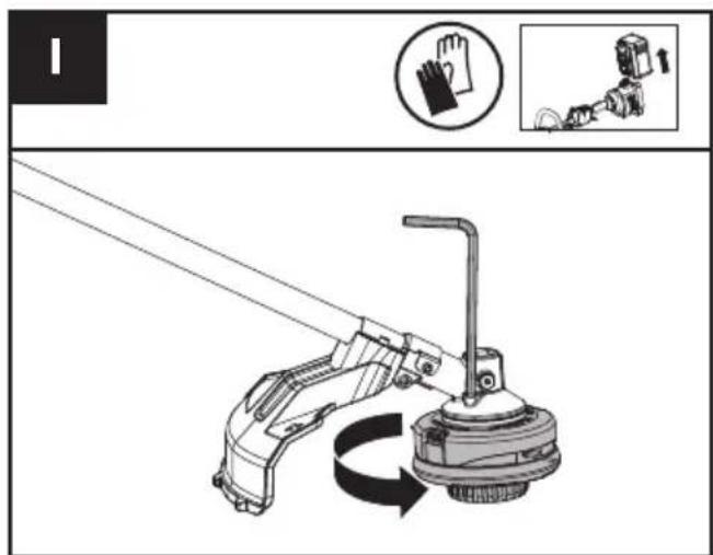
- Insert the hex key into the hole and rotate the trimmer head until it stops in a locked position.
- Then, rotate clockwise to remove it, and counterclockwise to assemble it.
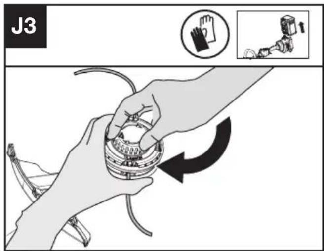
Winding the line (See Fig. J1, J2, J3)
- Rotate the spool cap to make two triangle icons
aligned. (See Fig. J1)
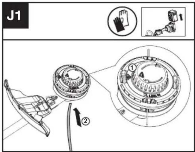
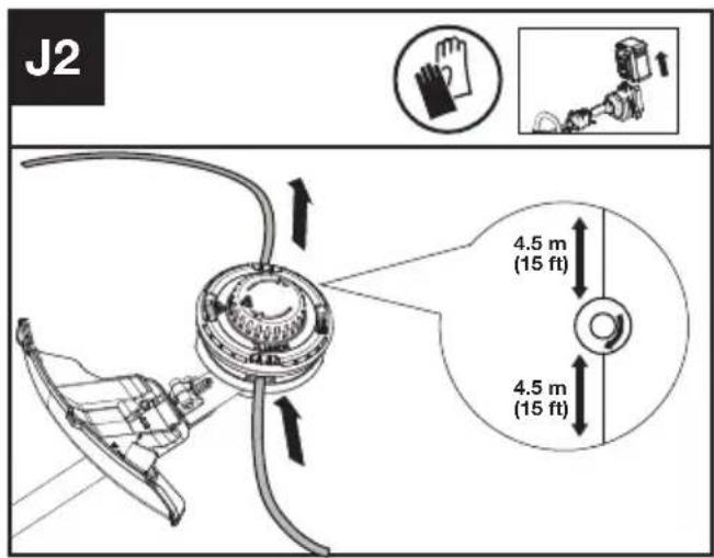
- Insert the replacement line through the eyelet (Line In) and feed it out through the other eyelet. Ensure both ends of the line are even on each end of the trimmer head (recommended 4.5 m (15 ft)) and cut the line. (See Fig. J2)
- Turn the dial clockwise to wind the line around the spool until about 16 cm (6") remains on either side. (See Fig. J3)
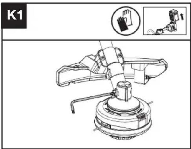
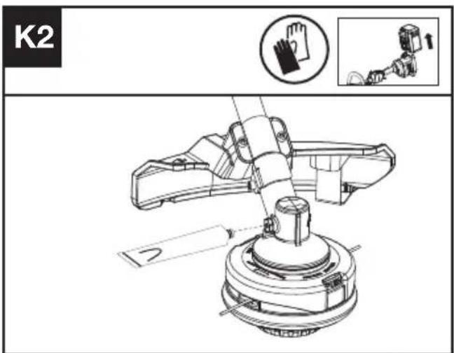
Lubricating the gearbox (See Fig. K1, K2)
- Remove the screw on the gearbox.
- If there is no bevel gear grease on the end of the screw, squeeze 5 g of the gear grease (SHELL
Gadus S2 V220 1) into the gear housing.
- Refit and tighten the screw firmly.
- Install the battery and run the trimmer for 1 minute to ensure the gear is evenly lubricated.
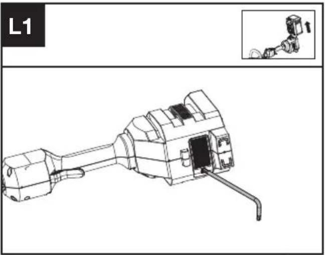
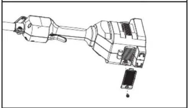
Cleaning the air filter (See Fig. L1, L2)
- Clean the area around the air filter. Use a damp cloth or a soft brush.
- Unscrew and remove the air filter.
- Wash the air filter with running water to remove the dirt.
- Allow the air filter to dry in the air. And then install it in the housing by thightening the screw.
natural_image
Technical line drawing of a mechanical component with an inset showing a close-up view (no text or symbols)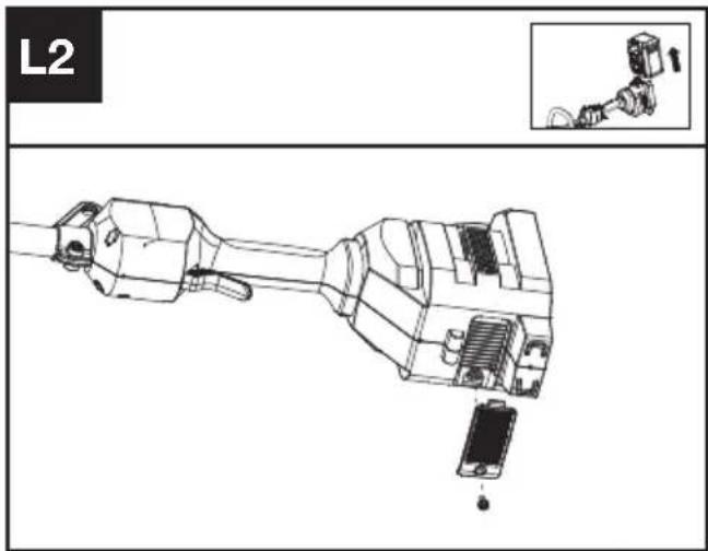
Maintenance intervals
It is recommended to lubricate the gearbox and clean the air filter every 50 hours of operation based on actual usage.
CLEANING
- Switch off the trimmer and remove the battery.
- Do not use aggressive detergents or solvents. Clean the machine after use with a damp cloth dipped in mild detergent.
- Keep battery connection free of dirt and debris, and clean with a soft and dry brush or cloth.
- Do not spray water onto the motor and electrical components.
- Do not use pressure washer to clean your machine.
STORAGE
- Remove the battery pack from the trimmer before storage.
- Once got wet in the rain during operation, the machine and the battery should be dried before storing or charging. Remove the battery and reinsert it if the machine fails to turn on.
- Store the trimmer and the battery in a dry and secure place that is inaccessible to children and other unauthorized people.
Remove the cutting attachment if it will not be used for a long time.
- Store the battery only within a temperature range between 5 °C (41 °F) and 25 °C (77 °F). As an example, do not leave the battery in the car in summer time.
TROUBLESHOOTING
The following table gives problems and actions that you can perform if your machine does not operate correctly.

WARNING: Switch the machine off and remove the battery prior to any troubleshooting.
TRIMMER
| Problems Possible | Causes Corrective Action | |
| Battery indicator LED flashing | Low battery voltage. Charge the battery. | |
| Red error LED flashing Overload. The cutting attachment is jammed | ||
BATTERY
| Problems Possible | Causes Corrective Action | |
| Error LED lit The battery is discharged | Charge the battery. If battery fails to charge, contact your Service Agent. | |
| Temperature issue. Use the battery in surroundings where temperatures are between -5°C and 45°C (23°F to 113°F) for charge; -20°C to 45°C (-4°F to 113°F) for discharge. | ||
| Others Contact your Service Agent. |
TECHNICAL DATA
Type Designation: KC100 KC100.X (1-designation of machinery, representative of Cordless Grass Trimmer)
| KC100 KC100.X ** | |
| Voltage | 60 V --- MAX *** |
| Cutting speed | 4200 / 5100 / 5900 rpm |
| Cutting diameter | 42 cm (16.5") |
| Line diameter | 2.4 / 2.7 mm (0.095'' / 0.105'') nylon line |
| Degree of protection IPX4 | |
| Machine weight (Bare tool) | 4.5 kg (9.9 lbs) |
** X=1-999,A-Z,M1-M9 they are only used for different customers, there are no safety relevant changes between these models.
*** Voltage measured without workload. Initial battery voltage reaches maximum of 60 volts. Nominal voltage is 54 volts.
SUGGESTED BATTERIES AND CHARGERS
| Battery Capacity | Charger Amperage | ||
| KAC804 4.0 Ah | KAC840 30 A | ||
| KAC810(With Backpack Harness) | 11.0 Ah |
We recommend that you purchase your accessories from the same Dealer that sold you the tool. Refer to the accessory packaging for further details. Your Dealer can assist you and offer advice.
TECHNICAL DATA FOR BATTERY PACK (OPTIONAL)
| Frequency bands for Bluetooth 2400-2483.5 MHz | |
| Maximum Output Power for Bluetooth | 8 dBm |
COMBINATIONS OF CUTTING ATTACHMENTS, DEFLECTORS, AND CARRYING SYSTEMS
| Cutting attachment Debris guard Barrier bar Carrying system | |||
| - 4" Trimmer head(Optional, not included)- 5" Trimmer head | - High-visibility deflector- Universal deflector with skirt | - Optional | - Shoulder strap- Backpack battery Harness |
| - Knife blade - Universal deflector without skirt | - Required | ||
NOISE INFORMATION
| A weighted sound pressure L | _pA = 79.7 dB(A) |
| K_pA | 3 dB(A) |
| A weighted sound power L | _wA = 94.94 dB(A) |
| K_wA | 0.59 dB(A) |
| Wear ear protection. | |
VIBRATION INFORMATION
| Typical weighted vibration a | _h = 2,45 m/s^2 |
| Uncertainty K = 3 m/s^2 | |
WARNING: The vibration emission value during actual use of the power tool can differ from the declared value depending on the ways in which the tool is used dependant on the following examples and other variations on how the tool is used:
How the tool is used and the materials being cut or drilled.
The tool being in good condition and well maintained The use the correct accessory for the tool and ensuring it is sharp and in good condition.
The tightness of the grip on the handles and if any anti-vibration accessories are used.
And the tool is being used as intended by its design and these instructions.
This tool may cause hand-arm vibration syndrome if its use is not adequately managed.
WARNING: To be accurate, an estimation of exposure level in the actual conditions of use should also take account of all parts of the operating cycle such as the times when the tool is switched off and when it is running idle but not actually doing the job. This may significantly reduce the exposure level over the total working period.
Helping to minimise your vibration exposure risk.
ALWAYS use sharp chisels, drills and blades
Maintain this tool in accordance with these instructions and keep well lubricated (where appropriate)
If the tool is to be used regularly then invest in anti vibration accessories.
Plan your work schedule to spread any high vibration tool use across a number of days.
ENVIRONMENTAL PROTECTION

Waste electrical products must not be disposed of with household waste. Please recycle where facilities exist. Check with your authorities or retailer for recycling advice.
DECLARATION OF CONFORMITY
We,
Positec Germany GmbH
Postfach 32 02 16, 50796 Cologne, Germany
On behalf of Positec declare that the product
Description Cordless Grass Trimmer
Type KC100 KC100.X (1-designation of machinery, representative of Cordless Grass Trimmer)
Function cutting grass and similar soft vegetation and for trimming grass edges
Complies with the following Directives:
2006/42/EC
2014/30/EU
2011/65/EU&(EU)2015/863
2000/14/EC amended by 2005/88/EC
2000/14/EC amended by 2005/88/EC:
- Conformity Assessment Procedure as per
- Measured Sound Power Level
- Declared Guaranteed Sound Power Level
Annex VI
94.94 dB (A)
96 dB (Å)
The notified body involved
Standards conform to
EN 62841-1, FprEN IEC
62841-4-4:2020+FprAA:2021-02, EN 62233,
EN ISO 3744, EN IEC 55014-1, EN IEC 55014-2
The person authorized to compile the technical file, Name Marcel Filz
Address Positec Germany GmbH
Postfach 32 02 16, 50796 Cologne, Germany

2022/12/5
Allen Ding
Deputy Chief Engineer, Testing & Certification
Positec Technology (China) Co., Ltd
18, Dongwang Road, Suzhou Industrial
Park, Jiangsu 215123, P. R. China
DECLARATION OF CONFORMITY
We,
Positec (UK & Ireland) Ltd
PO Box 6242, Newbury, RG14 9LT, UK
On behalf of Positec declare that the product
Description Cordless Grass Trimmer
Type KC100 KC100.X (1-designation of machinery, representative of Cordless Grass Trimmer)
Function cutting grass and similar soft vegetation and for trimming grass edges
Complies with the following Directives:
Supply of Machinery (Safety) Regulations 2008
Electromagnetic Compatibility Regulations 2016
The Restriction of the Use of Certain Hazardous
Substances in Electrical and Electronic
Equipment Regulations
Noise Emission in the Environment by Equipment for Use Outdoors Regulations
- Conformity Assessment Procedure as per SCHEDULE 9
- Measured Sound Power Level 94.94 dB (A)
- Declared Guaranteed Sound Power Level 96 dB (A)
The notified body involved
Standards conform to
BS EN 62841-1, FprBS EN IEC
62841-4-4:2020+FprAA:2021-02, BS EN 62233,
BS EN ISO 3744, BS EN IEC 55014-1, BS EN IEC 55014-2
The person authorized to compile the technical file,
Name Jim Kirkwood
Address Positec (UK & Ireland) Ltd,
PO Box 6242, Newbury, RG14 9LT, UK


2022/12/5
Allen Ding
Deputy Chief Engineer, Testing & Certification
Positec Technology (China) Co., Ltd
18, Dongwang Road, Suzhou Industrial
Park, Jiangsu 215123, P. R. China
INHALTSVERZEICHNIS
Einführung....18
Komponenten....19
KOMPONENTEN
18, Dongwang Road, Suzhou Industrial
Park, Jiangsu 215123, P. R. China
SOMMAIRE
Introduction....34
LISTE DES COMPOSANTS
- BOUTONS DE RÉGLAGE DE LA VITESSE
- INTERRUPTEUR MARCHE/ARRÊT
- VERROU DE PACK BATTERIE
- PACK BATTERIE *
- MANETTE DES GAZ
- BOUTON DE PRÉSENCE DE L'OPÉRATEUR
- SUPPORT DE BANDOULIÈRE
- FLASQUE
- PROTECTION ANTI-DÉBRIS
- TÊTE DE COUPE
- FRONT HANDLE
- COUVERCLE DE BOBINE
- BOBINE
- LOQUET DE DÉVERROUILLAGE DE COUVERCLE
- ŒILLET
- BANDOULIÈRE *
NOTICE ORIGINALE AVERTISSEMENTS DE SÉCURITÉ SÉCURITÉ DU PRODUIT AVERTISSEMENTS GÉNÉRAUX DE SÉCURITÉ POUR L'OUTIL

INFORMATIONS RELATIVES AU BRUIT
INFORMATIONS RELATIVES AUX VIBRATIONS
18, Dongwang Road, Suzhou Industrial
Park, Jiangsu 215123, P. R. China
INDICE
Introduzione....49
ELEMENTI DELL'APPARECCHIO
- CONTROLLO DELLA VELOCITA'
- INTERRUTTORE ON/OFF
- SERRATURA A SCATTO UNITÀ BATTERIA
- UNITÀ BATTERIA *
- GRILLETTO DELL'ACCELERATORE
- INTERRUTTORE DI PRESENZA DELL'OPERATORE
- SUPPORTO PER TRACOLLA
- ALBERO
- PROTEZIONE ANTI-DETRITI
- TESTA DI TAGLIO
- MANIGLIA ANTERIORE
- COPRI BOBINA
- BOBINA
- CHIUSURA DI RILASCIO DEL CAPPUCCIO
- OCCHIELLO
- TRACOLLA *
ISTRUZIONI ORIGINALI AVVISI GENERALI PER LA SICUREZZA E PER LA SICUREZZA DEGLI UTENSILI A MOTORE

natural_image
Technical line drawing of a mechanical component with no visible text or symbols
natural_image
Technical line drawing of a mechanical assembly with no visible text or symbols18, Dongwang Road, Suzhou Industrial
Park, Jiangsu 215123, P. R. China
ÍNDICE
Introducción....64

natural_image
Technical line drawing of a mechanical component with an inset showing a close-up view (no text or symbols)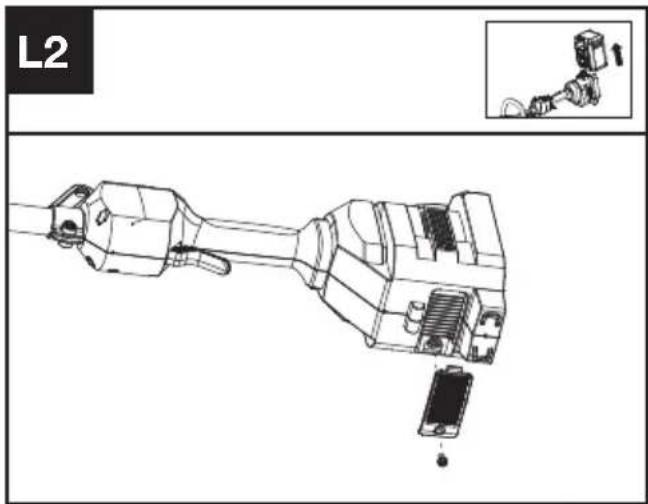
18, Dongwang Road, Suzhou Industrial
Park, Jiangsu 215123, P. R. China
ÍNDICE
Introdução....79
Lista de componentes....80
18, Dongwang Road, Suzhou Industrial
Park, Jiangsu 215123, P. R. China
INHOUDSOPGAVE
Inleiding....94
DRIE SNELHEIDSINSTELLINGEN
- SNELHEIDSREGELING
- AAN/UIT-SCHAKELAAR
- ONTGRENDELPAL ACCU
- ACCUPACK *
- GASHENDEL
- AANWEZIGHEIDSSCHAKELAAR
- SCHOUDERRIEMBEVESTIGING
- SCHACHT
- BESCHERMKAP
- FIJNAFSTEMMINGSKOP
- VOORSTE HANDGREEP
- SPOELKAP
- SPOEL
- KAPONTGRENDELING
- HANGOOG
- SCHOUDER RIEM *
OORSPRONKELIJKE GEBRUI- KSAANWIJZING VEILIGHEIDSWAARSCHUWINGEN ALGEMENE VEILIGHEIDSWAARSCHUWINGEN VOOR VERMOGENSMACHINE

WAARSCHUWING: Lees alle veiligheidswaarschuwingen,
VEILIGHEIDSWAARSCHUWINGEN
VOOR BOSMAAIERS EN GRASTRIMMERS
natural_image
Technical line drawing of a mechanical component with an inset showing a close-up view (no text or symbols)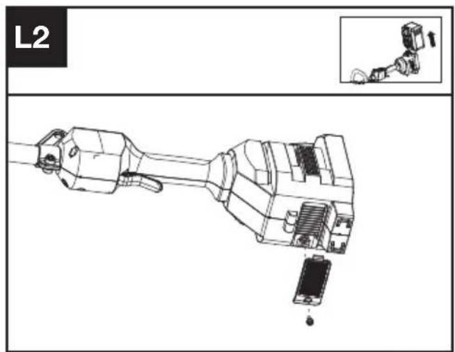
18, Dongwang Road, Suzhou Industrial
Park, Jiangsu 215123, P. R. China
CUPRINS
Introducere....125
LISTA DE COMPONENTE
- CONTROLUL VITEZEI
- BUTON DE PORNIRE/OPRIRE
- BUTON DE ELIBERARE A ACUMULATORULUI
- ACUMULATOR *
- BUTONUL DE ACCELERATIE
- COMUTATORUL DE PREZENTĂ A UTILIZATORULUI
- SUPORT CUREA DE UMĂR
- ARBORE
- PROTECTIEI ÎMPOTRIVA RESTURILOR
- CAP DE REGLARE FINĂ
- MÂNERULUI FRONTAL
- CAPAC BOBINĂ
- BOBINĂ
- OPRITOR ELIBERARE CAPAC
- ORIFICIU
- CUREA DE UMĂR *
INSTRUCTIUNI ORIGINALE SECURITATEA PRODUSULUI AVERTISMENTE GENERALE DE SIGURANTĂ PENTRU UNELTE ELECTRICE

18, Dongwang Road, Suzhou Industrial
Park, Jiangsu 215123, P. R. China
SPIS TREŚCI
Wprowadzenie....140
LISTA KOMPONENTÓW
natural_image
Technical line drawing of a mechanical component with an inset showing a close-up view (no text or symbols)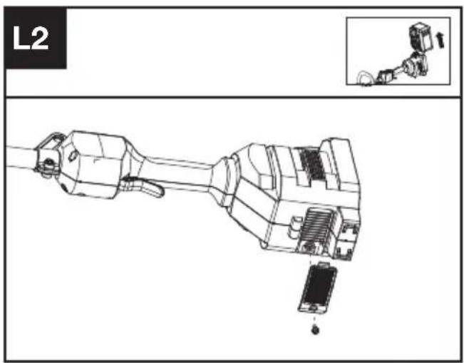
Interwały obsługi
18, Dongwang Road, Suzhou Industrial
Park, Jiangsu 215123, P. R. China
OBSAH
Úvod....155
SEZNAM KOMPONENT
- REGULACE RYCHLOSTI
- HLAVNÍ VYPÍNAČ
- UVOLŇOVACÍ TLAČÍTKO BATERIE
- AKUMULÁTOR *
- SPOUŠT ŠKRTICÍ KLAPKY
- SPÍNAČ PŘÍTOMNOSTI OBSLUHY
- DRŽÁK NA RAMENNÍ POPRUH
- RUKOJETI
- OCHRANNÉHO KRYTU PROTI NEČISTOTÁM
- JEMNĚ VYLADĚNÁ HLAVA
- PŘEDNÍ RUKOJETI
- KRYT CÍVKY
- CÍVKA
- UVOLŇOVACÍ ZÁPADKA KRYTU
- OČKO
- RAMENNÍ POPRUH *
PŮVODNÍ NÁVOD K POUŽÍVÁNÍ BEZPEČNOST VÝROBKU OBECNÁ BEZPEČNOSTNÍ UPOZORNĚNÍ PRO ELEKTRICKÉ NÁSTROJE
INFORMACE TÝKAJÍCÍ SE HLUČNOSTI
18, Dongwang Road, Suzhou Industrial
Park, Jiangsu 215123, P. R. China
OBSAH
Úvod....170
ZOZNAM SÚČASTÍ
- OVLÁDANIE RÝCHLOSTI
- TLAČIDLO ZAPNÚŤ/VYPNÚŤ
- UVOLŇOVACÍ TLAČÍTKO BATERIE
- BATÉRIOVÝ *
- ŠKRTIACA KLAPKA
- SPÍNAČ PRÍTOMNOSTI OPERÁTORA
- DRŽIAK NA RAMENNÝ POPRUH
- TYČ
- OCHRANNÉHO KRYTU PROTI ÚLOMKOM
- JEMNE VYLADENÁ HLAVA
- PREDNEJ RUKOVÄTE
- UZÁVER CIEVKY
- CIEVKA
- ZÁPADKA NA UVOL'NENIE VIEČKA
- OČKO
- RAMENNÝ POPRUH *
PÔVODNÝ NÁVOD NA POUŽITIE BEZPEČNOSTŠT VÝROBKU VŠEOBECNÉ BEZPEČNOSTNÉ UPOZORNENIA
18, Dongwang Road, Suzhou Industrial
Park, Jiangsu 215123, P. R. China
KAZALO VSEBINE
Uvod....185
Sestavni deli....186
Varnost izdelka....187
Sestavljanje in delovanje....191
Transport....194
Vzdrževanje....194
Čiščenje....196
Shranjevanje....196
Odpravljanje napak....197
SESTAVNI DELI
- KRMILNIK HITROSTI
- STIKALO ZA VKLOP/IZKLOP
- GUMB ZA SPROSTITEV AKUMULATORJA
- AKUMULATOR *
- SPROŽILEC PLINA
- STIKALO PRISOTNOSTI ZA UPRAVLJAVCA
- NASTAVEK ZA NARAMNICO
- GREDI
- ŠČITNIKA ZA OBREZKE
- GLAVA ZA FINO NASTAVITEV
- SPREDNJEGA ROČAJA
- POKROVČEK MOTKA
- MOTEK
- ZAPAH ZA SPROSTITEV POKROVČKA
- OBROČEK
- NARAMNI PAS *
IZVIRNA NAVODILA VARNOST IZDELKA SPLOŠNA VARNOSTNA OPOZORILA

- Vstavite šestrobni ključ v luknjo in vrtite glavo obrezovalnika, dokler se ne zaustavi v zaklenjenem položaju.
- Da jo odstranite, jo zavrtite v smeri urinega kazalca, in zavrtite v nasprotni smeri uronega kazalca, da jo pritrdite nazaj.
Navijanje trimer linije (Glejte sliko. J1, J2, J3)
18, Dongwang Road, Suzhou Industrial
Park, Jiangsu 215123, P. R. China
SADRŽAJ
Uvod....200
Popis komponenti....201
Sigurnost proizvoda....202
Sastavljanje i rad....206
Transport....209
Održavanje....209
Čišćenje....210
Skladištenje....210
Otklanjanje poteškoća....211
Tehnički podaci....211
HR
Zaštita okoliša....212
Izjava o sukladnosti....213
UVOD
Poštovani,
POPIS KOMPONENTI
- KONTROLA BRZINE
- PREKIDAČ ON/OFF (UKLJUČENO/ISKLJUČENO)
- OTVARANJE BATERIJSKOG MODULA
- BATERIJSKI KOMPLET *
- AKTIVATOR GASA
- PREKIDAČ PRISUTNOSTI RUKOVATELJA
- MONTIRANJE NARAMENICE
- OSOVINA
- ŠTITNIK OD KRHOTINA
- GLAVA TRIMERA
- PREDNJA RUČKA
- POKLOPAC KALEMA
- KALEM
- ZASUN ZA OTPUŠTANJE POKLOPCA
- UŠICA
- NARAMENICA*
ORIGINALNE UPUTE ZA RAD SIGURNOST PROIZVODA UOBIČAJENA SIGURNOSNA UPOZORENJA ZA ELEKTRIČNE ALATE

UPOZORENJE Pročitajte sva sigurnosna upozorenja, upute,
ilustracije i specifikacije koje se isporučuju s ovim električnim alatom. Nepoštivanje dolje navedenih uputa može uzrokovati električni udar, požar i/ili ozbiljne ozljede.
SPAJANJE S POJASOM ZA RUKSAK (VIDI SL. D3)
- Umetnite šesterokutni ključ u rupu i okrenite glavu trimera dok se ne zaustavi u zaključanom
položaju.
natural_image
Technical line drawing of a mechanical component with an inset showing a small mechanical assembly (no text or symbols)18, Dongwang Road, Suzhou Industrial
Park, Jiangsu 215123, P. R. China
INDHOLDSFORTEGNELSE
Introduktion....214
18, Dongwang Road, Suzhou Industrial
Park, Jiangsu 215123, P. R. China
SISÄLLYSLUETTELO
Johdanto....228
Komponenttiluettelo....229
KOMPONENTTILUETTELO
- NOPEUDENSÄÄTÖ
- ON/OFF-VIRTAKYTKIN
- AKKUYKSIKÖN VAPAUTUSPAINIKE
- AKKUYKSIKKÖ *
- KAASULIIPAISIN
- KÄYTTÄJÄN LÄSNÄOLOKYTKIN
- OLKAHIHNAN ASENNUSKOHTA
- VARI SI
- ROSKASUOJA
- TRIMMERIPÄÄ
- ETUKAHVA
- KELAN KORKKI
- KELA
- KORKIN VAPAUTUSSALPA
- SILMUKKA
- OLKAHIHNA *
ALKUPERÄISET OHJEET TURVALLISUUSOHJEET TUOTETURVALLISUUS YLEISET SÄHKÖTYÖKALUJEN TURVALLISUUTEEN LIITTYVÄT VAROITUKSET
18, Dongwang Road, Suzhou Industrial
Park, Jiangsu 215123, P. R. China
INNHOLDFORTEGNELSE
Introduksjon....242
Komponentliste....243
Transportation....251
Vedlikehold....251
Rengjøring....252
Lagring....252
Feilsøking....253
APPARATELEMENTER
- HASTIGHETSKONTROLL
- AV/PÅ-BRYTER
- LÅS FOR BATTERIPAKKE
- BATTERIPAKKE *
- GASSBRYTER
- BRYTER FOR OPERAT∅RTILSTEDEVÆRELSE
- SHOULDER STRAP MOUNT
- SHAFT
- BESKYTTELSESSKJERMEN
- FINJUSTERINGSHODE
- HÅNDTAKET FORAN
- SPOLEDEKSEL
- SPOLE
- LÅS FOR UTL∅SNING AV DEKSEL
- MALJE
- SKULDERREM *
ORIGINAL DRIFTSINSTRUKS PRODUKTSIKKERHET GENERELLE ADVARSLER FOR ELEKTROVERKT∅Y

ADVARSEL Les alle
KOBLE TIL SELENE FOR RYGGBÆRING (SE FIG. D3)

18, Dongwang Road, Suzhou Industrial
Park, Jiangsu 215123, P. R. China
INNEHÅLLSFÖRTECKNING
Introduktion....256
Komponenter....257
Produktsäkerhet 258
Transportation....264
Underhåll....265
Rengöring....266
Förvaring....266
Felsökning....267
Tekniska data....268
Miljöskydd....269
KOMPONENTER
- HASTIGHETSKONTROLL
- STRÖMBRYTARE PÅ/AV
- BATTERIPAKETETS LÅSNING
- BATTERIPAKET *
- GASREGLAGE FÖR DRIFT
- GASSPÄRREN
- AXELREMSFÄSTE
- SKAFT
- SKRÄPSKYDD
- FINJUSTERANDE HUVUD
- FRÄMRE HANDTAG
- SPOLLOCK
- SPOLE
- LÅSHAKE LOCK
- ÖGLA
- AXELREM *
BRUKSANVISNING I ORIGINAL SÄKERHETSFÖRESKRIFTER SÄKERHETSVARNINGAR GENERELLA SÄKERHETS-VARNINGAR FÖR ELVERK-TYG

ANSLUTNING MED RYGGSELEN (SE FIGUR D3)
natural_image
Technical line drawing of a mechanical component with an inset showing a close-up view (no text or symbols)18, Dongwang Road, Suzhou Industrial
Park, Jiangsu 215123, P. R. China

Copyright © 2023, Positec. All Rights Reserved.
AR01693101


- TABLE OF CONTENTS
- INTRODUCTION
- INTENDED USE
- COMPONENT LIST
- ORIGINAL INSTRUCTIONS PRODUCT SAFETY GENERAL POWER TOOL SAFETY WARNINGS
- Save all warnings and instructions for future reference.
- BRUSH CUTTER AND BRUSH
- SAW SAFETY WARNINGS
- BLADE THRUST CAUSES AND RELATED WARNINGS
- SAFETY WARNINGS FOR BATTERY PACK
- USER MANUAL REQUIREMENTS FOR WIRELESS PRODUCT
- SYMBOLS
- BEFORE OPERATION:
- Assembling the cutting head (See Fig. A1)
- Fitting the shoulder strap (Sold Separately) (See Fig. C)
- Installing & removing the battery pack (See Fig. D1, D2)
- Connecting with the backpack harness (See Fig. D3)
- TESTING THE TRIMMER AND BATTERY (See Fig. E)
- Checking the controls Operator Presence Switch and Throttle Trigger
- Checking the display
- OPERATION: Starting the trimmer (See Fig. F1, F2)
- Selecting the speed
- Stopping the trimmer
- Bump-line feed system (See Fig. G)
- Cutting Tips (See Fig. H)
- For Battery tools
- TRANSPORTATION
- Transporting the trimmer
- Transporting the battery
- MAINTENANCE
- Replacing the trimmer head (See Fig. I)
- Winding the line (See Fig. J1, J2, J3)
- Lubricating the gearbox (See Fig. K1, K2)
- Cleaning the air filter (See Fig. L1, L2)
- Maintenance intervals
- CLEANING
- STORAGE
- TROUBLESHOOTING
- TECHNICAL DATA
- SUGGESTED BATTERIES AND CHARGERS
- TECHNICAL DATA FOR BATTERY PACK (OPTIONAL)
- COMBINATIONS OF CUTTING ATTACHMENTS, DEFLECTORS, AND CARRYING SYSTEMS
- ENVIRONMENTAL PROTECTION
- DECLARATION OF CONFORMITY
- INHALTSVERZEICHNIS
- KOMPONENTEN
- SOMMAIRE
- LISTE DES COMPOSANTS
- NOTICE ORIGINALE AVERTISSEMENTS DE SÉCURITÉ SÉCURITÉ DU PRODUIT AVERTISSEMENTS GÉNÉRAUX DE SÉCURITÉ POUR L'OUTIL
- INFORMATIONS RELATIVES AU BRUIT
- INFORMATIONS RELATIVES AUX VIBRATIONS
- INDICE
- ELEMENTI DELL'APPARECCHIO
- ISTRUZIONI ORIGINALI AVVISI GENERALI PER LA SICUREZZA E PER LA SICUREZZA DEGLI UTENSILI A MOTORE
- ÍNDICE
- INHOUDSOPGAVE
- DRIE SNELHEIDSINSTELLINGEN
- OORSPRONKELIJKE GEBRUI- KSAANWIJZING VEILIGHEIDSWAARSCHUWINGEN ALGEMENE VEILIGHEIDSWAARSCHUWINGEN VOOR VERMOGENSMACHINE
- VEILIGHEIDSWAARSCHUWINGEN
- VOOR BOSMAAIERS EN GRASTRIMMERS
- CUPRINS
- LISTA DE COMPONENTE
- INSTRUCTIUNI ORIGINALE SECURITATEA PRODUSULUI AVERTISMENTE GENERALE DE SIGURANTĂ PENTRU UNELTE ELECTRICE
- SPIS TREŚCI
- LISTA KOMPONENTÓW
- Interwały obsługi
- OBSAH
- SEZNAM KOMPONENT
- PŮVODNÍ NÁVOD K POUŽÍVÁNÍ BEZPEČNOST VÝROBKU OBECNÁ BEZPEČNOSTNÍ UPOZORNĚNÍ PRO ELEKTRICKÉ NÁSTROJE
- ZOZNAM SÚČASTÍ
- PÔVODNÝ NÁVOD NA POUŽITIE BEZPEČNOSTŠT VÝROBKU VŠEOBECNÉ BEZPEČNOSTNÉ UPOZORNENIA
- KAZALO VSEBINE
- SESTAVNI DELI
- IZVIRNA NAVODILA VARNOST IZDELKA SPLOŠNA VARNOSTNA OPOZORILA
- Navijanje trimer linije (Glejte sliko. J1, J2, J3)
- SADRŽAJ
- UVOD
- POPIS KOMPONENTI
- ORIGINALNE UPUTE ZA RAD SIGURNOST PROIZVODA UOBIČAJENA SIGURNOSNA UPOZORENJA ZA ELEKTRIČNE ALATE
- SPAJANJE S POJASOM ZA RUKSAK (VIDI SL. D3)
- INDHOLDSFORTEGNELSE
- SISÄLLYSLUETTELO
- KOMPONENTTILUETTELO
- ALKUPERÄISET OHJEET TURVALLISUUSOHJEET TUOTETURVALLISUUS YLEISET SÄHKÖTYÖKALUJEN TURVALLISUUTEEN LIITTYVÄT VAROITUKSET
- INNHOLDFORTEGNELSE
- APPARATELEMENTER
- ORIGINAL DRIFTSINSTRUKS PRODUKTSIKKERHET GENERELLE ADVARSLER FOR ELEKTROVERKT∅Y
- KOBLE TIL SELENE FOR RYGGBÆRING (SE FIG. D3)
- INNEHÅLLSFÖRTECKNING
- KOMPONENTER
- BRUKSANVISNING I ORIGINAL SÄKERHETSFÖRESKRIFTER SÄKERHETSVARNINGAR GENERELLA SÄKERHETS-VARNINGAR FÖR ELVERK-TYG
- ANSLUTNING MED RYGGSELEN (SE FIGUR D3)
Brand : KRESS
Model : KC100.9
Category : String Trimmer