USER MANUAL KC170.9 KRESS
natural_image
Mechanical tool with articulated arms and a flat base (no text or symbols visible)
| 60V Commercial Brush Cutter | EN | P02 |
| Gewerblicher Freischneider 60 V | D | P21 |
| Débroussailleuse commerciale 60 V | F | P40 |
| Decespugliatore Commercial 60 V | I | P59 |
| Desbrozadora Commercial de 60V | ES | P78 |
| Roçadora Comercial de 60 V | PT | P97 |
| 60V Commerciële bosmaaier | NL | P116 |
| 60V Commerciële bosmaaier | HU | P135 |
| Trimmer comercial pentru gard viu, 60 V | RO | P154 |
| Profesjonalna wykaszarka do trawy i zarośli 60 V | PL | P173 |
| 60 V křovinořez pro komerční použití | CZ | P192 |
| 60 V komerčný krovinorez | SK | P211 |
| 60-V komercialna motorna kosa | SL | P230 |
| Komercijalni rezač grmlja 60 V | HR | P248 |
| 60 V kommerciel buskrydder | DK | P266 |
| 60 V Pensasleikkuri | FIN | P284 |
| 60 V kommersiell krattkutter | NOR | P302 |
| 60V kommersiell röjsåg | SV | P320 |
KC170 KC170.X
TABLE OF CONTENTS
Introduction....2
Component List....4
Product Safety....5
Assembly & Operation....9
Transportation....13
Maintenance....13
Cleaning....15
Storage....15
Troubleshooting....16
Technical Data....17
EN
Environmental Protection....18
Declaration of Conformity....19
INTRODUCTION
Dear Customer,
Thank you for buying this Kress Commercial product. We are dedicated to developing high quality products to meet your commercial landscaping requirements.
The Kress brand is synonymous with premium quality service. Over the years of your product's life, if you have any questions or concerns about your product, please contact your dealer or our Customer Service Team for assistance.
We are confident you will enjoy working with your Kress product for years to come.
INTENDED USE
This machine is intended for cutting grass and high weeds that cannot be reached with a lawn mower. This machine is also used on areas with slopes not conducive to mowing.
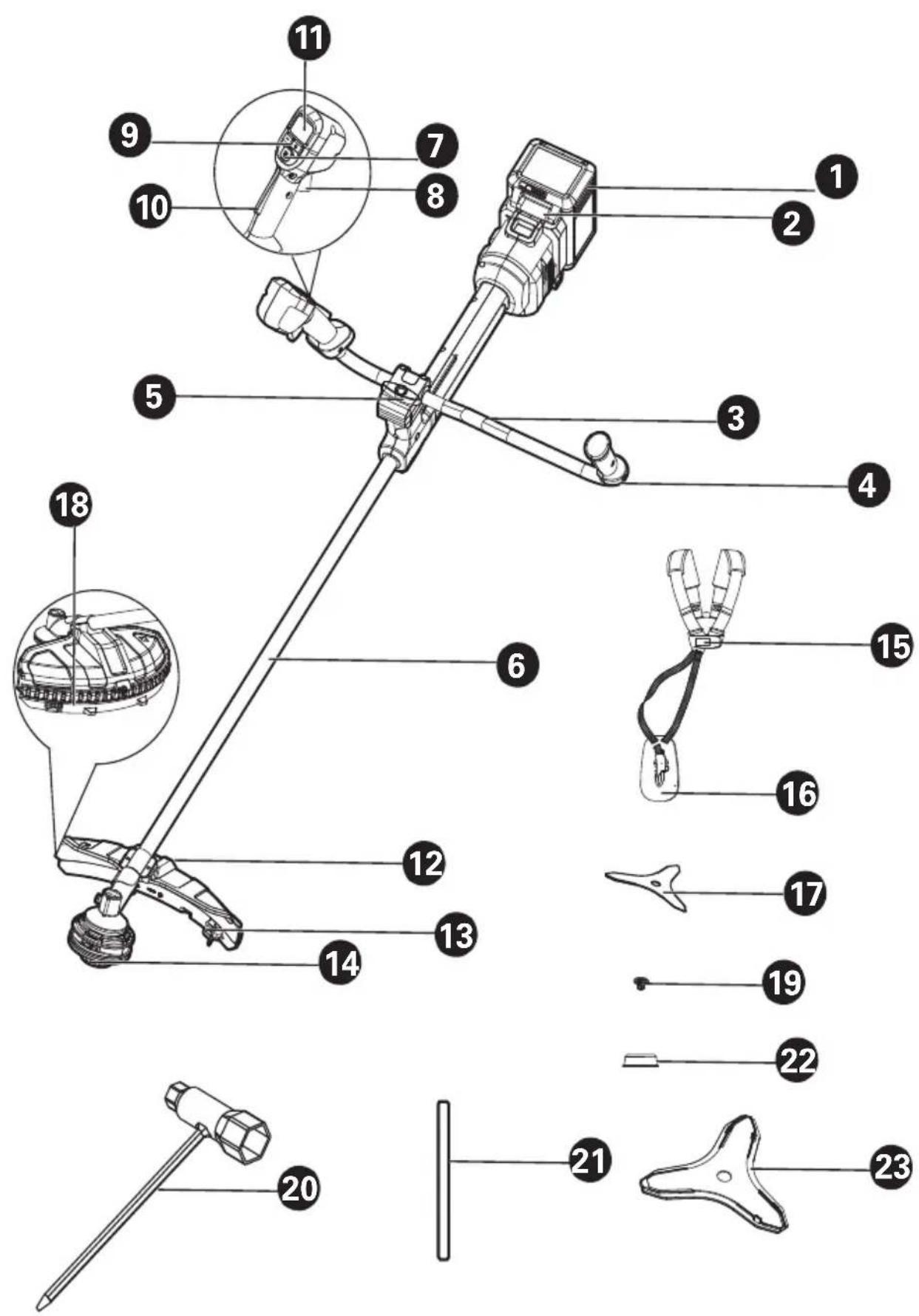
COMPONENT LIST
-
BATTERY PACK *
-
BATTERY REALEASE BUTTON
-
BIKE HANDLE
-
HAND GRIP
-
CLAMP BOLT
-
SHAFT
-
ON/OFF BUTTON
-
THROTTLE TRIGGER
-
CONTROL BUTTON
-
OPERATOR PRESENCE SWITCH
-
SCREEN
-
GUARD ASSEMBLY
-
LINE-CUTTING BLADE
-
TRIMMER HEAD
-
HARNESS BUCKLE
-
HIP-PAD
-
3-TEETH BLADE
-
SKIRT
-
NUT
20.ALLEN WRENCH
21.STOP PIN
-
BLADE FIXED COVER
-
BLADE SHEATH
* Not all the accessories illustrated or described are included in standard delivery.

WARNING Read all safety warnings, instructions, illustrations and specifications
provided with this power tool. Failure to follow all instructions listed below may result in electric shock, fire and/or serious injury.
Save all warnings and instructions for future reference.
The term "power tool" in the warnings refers to your mains-operated (corded) power tool or battery-operated (cordless) power tool.
1) Work area safety
a) Keep work area clean and well lit. Cluttered or dark areas invite accidents.
b) Do not operate power tools in explosive atmospheres, such as in the presence of flammable liquids, gases or dust. Power tools create sparks which may ignite the dust or fumes.
c) Keep children and bystanders away while operating a power tool. Distractions can cause you to lose control.
2) Electrical safety
a) Power tool plugs must match the outlet. Never modify the plug in any way. Do not use any adapter plugs with earthed (grounded) power tools. Unmodified plugs and matching outlets will reduce risk of electric shock.
b) Avoid body contact with earthed or grounded surfaces, such as pipes, radiators, ranges and refrigerators. There is an increased risk of electric shock if your body is earthed or grounded.
c) Do not operate the machine in rain or wet conditions. This may increase the risk of electric shock. Once got wet in the rain during operation, the machine and the battery should be dried before storing or charging. Remove the battery and reinsert it if the machine fails to turn on. Keep battery connection free of dirt and debris, and clean with a soft and dry brush or cloth.
d) Do not abuse the cord. Never use the cord for carrying, pulling or unplugging the power tool. Keep cord away from heat, oil, sharp edges or moving parts. Damaged or entangled cords increase the risk of electric shock.
e) When operating a power tool outdoors, use an extension cord suitable for outdoor use. Use of a cord suitable for outdoor use reduces the risk of electric shock.
f) If operating a power tool in a damp location is unavoidable, use a residual current device (RCD) protected supply. Use of an RCD reduces the risk of electric shock.
3) Personal safety
a) Stay alert, watch what you are doing and use common sense when operating a power tool. Do not use a power tool while you are tired or under the influence of drugs, alcohol or medication. A moment of inattention while operating power tools may result in serious personal injury.
b) Use personal protective equipment. Always wear eye protection. Protective equipment such as dust mask, non-skid safety shoes, hard hat, or hearing protection used for appropriate conditions will reduce personal injuries.
c) Prevent unintentional starting. Ensure the switch is in the off-position before connecting to power source and/or battery pack, picking up or carrying the tool. Carrying power tools with your finger on the switch or energising power tools that have the switch on invites accidents.
d) Remove any adjusting key or wrench before turning the power tool on. A wrench or a key left attached to a rotating part of the power tool may result in personal injury.
e) Do not overreach. Keep proper footing and balance at all times. This enables better control of the power tool in unexpected situations.
f) Dress properly. Do not wear loose clothing or jewellery. Keep your hair and clothing away from moving parts. Loose clothes, jewellery or long hair can be caught in moving parts.
g) If devices are provided for the connection of dust extraction and collection facilities, ensure these are connected and properly used. Use of dust collection can reduce dust-related hazards.
h) Do not let familiarity gained from frequent use of tools allow you to become complacent and ignore tool safety principles. A careless action can cause severe injury within a fraction of a second.
4) Power tool use and care
a) Do not force the power tool. Use the correct power tool for your application. The correct power tool will do the job better and safer at the rate for which it was designed.
b) Do not use the power tool if the switch does not turn it on and off. Any power tool that cannot be controlled with the switch is dangerous and must be repaired.
c) Disconnect the plug from the power source and/or remove the battery pack, if detachable, from the power tool before making any adjustments, changing accessories, or storing power tools. Such preventive safety measures reduce the risk of starting the power tool accidentally.
d) Store idle power tools out of the reach of children and do not allow persons unfamiliar with the power tool or these instructions to operate the power tool. Power tools are dangerous in the hands of untrained users.
e) Maintain power tools and accessories. Check for misalignment or binding of moving parts, breakage of parts and any other condition that may affect the power tool's operation.
If damaged, have the power tool repaired before use. Many accidents are caused by poorly maintained power tools.
f) Keep cutting tools sharp and clean. Properly maintained cutting tools with sharp cutting edges are less likely to bind and are easier to control.
g) Use the power tool, accessories and tool bits etc. in accordance with these instructions, taking into account the working conditions and the work to be performed. Use of the power tool for operations different from those intended could result in a hazardous situation.
h) Keep handles and grasping surfaces dry, clean and free from oil and grease. Slippery handles and grasping surfaces do not allow for safe handling and control of the tool in unexpected situations.
5) Battery tool use and care
a) Recharge only with the charger specified by the manufacturer. A charger that is suitable for one type of battery pack may create a risk of fire when used with another battery pack.
b) Use power tools only with specifically designated battery packs. Use of any other battery packs may create a risk of injury and fire.
c) When battery pack is not in use, keep it away from other metal objects, like paper clips, coins, keys, nails, screws or other small metal objects, that can make a connection from one terminal to another. Shorting the battery terminals together may cause burns or a fire.
d) Under abusive conditions, liquid may be ejected from the battery; avoid contact. If contact accidentally occurs, flush with water. If liquid contacts eyes, additionally seek medical help.
Liquid ejected from the battery may cause irritation or burns.
e) Do not use a battery pack or tool that is damaged or modified. Damaged or modified batteries may exhibit unpredictable behaviour resulting in fire, explosion or risk of injury.
f) Do not expose a battery pack or tool to fire or excessive temperature. Exposure to fire or temperature above 130 °C may cause explosion.
g) Follow all charging instructions and do not charge the battery pack or tool outside the temperature range specified in the instructions. Charging improperly or at temperatures outside the specified range may damage the battery and increase the risk of fire.
6) Service
a) Have your power tool serviced by a qualified repair person using only identical replacement parts. This will ensure that the safety of the power tool is maintained.
b) Never service damaged battery packs. Service of battery packs should only be performed by the manufacturer or authorized service providers.
BRUSH CUTTER AND BRUSH
SAW SAFETY WARNINGS
a) Do not use the machine in bad weather conditions, especially when there is a risk of lightning. This decreases the risk of being struck by lightning.
b) Thoroughly inspect the area for wildlife where the machine is to be used. Wildlife may be injured by the machine during operation.
c) Thoroughly inspect the area where the machine is to be used and remove all stones, sticks, wires, bones, and other foreign objects. Thrown objects can cause personal injury.
d) Before using the machine, always visually inspect to see that the cutter or blade and the cutter or blade assembly are not damaged. Damaged parts increase the risk of injury.
e) Follow instructions for changing accessories.
Improperly tightened blade securing nuts or bolts may either damage the blade or result in it becoming detached.
f) The rated rotational speed of the blade must be at least equal to the maximum rotational speed marked on the machine. Blades running faster than their rated rotational speed can break and fly apart.
g) Wear eye, ear, head and hand protection.
Adequate protective equipment will reduce personal injury by flying debris or accidental contact with the cutting line or blade.
h) While operating the machine, always wear safety footwear. Do not operate the machine when barefoot or wearing open sandals. This reduces the chance of injury to the feet from contact with a moving cutter, line or blade.
i) While operating the machine, always wear long trousers. Exposed skin increases the likelihood of injury from thrown objects.
j) Keep bystanders away while operating the machine. Thrown debris can result in serious personal injury.
k) Always use two hands when operating the machine. Holding the machine with both hands will avoid loss of control.
I) Hold the machine by the insulated gripping surfaces only, because the cutting line or blade may contact hidden wiring. Cutting line or blades contacting a "live" wire may make exposed metal parts of the machine "live" and could give the operator an electric shock.
m) Always keep proper footing and operate the machine only when standing on the ground.
Slippery or unstable surfaces may cause a loss of balance or control of the machine.
n) Do not operate the machine on excessively steep slopes. This reduces the risk of loss of control, slipping and falling which may result in personal injury.
o) When working on slopes, always be sure of your footing, always work across the face of slopes, never up or down and exercise extreme caution when changing direction. This reduces the risk of loss of control, slipping and falling which may result in personal injury.
p) Keep all parts of the body away from the cutter, line or blade when the machine is operating. Before you start the machine, make sure the cutter, line or blade is not contacting anything.
A moment of inattention while operating the machine may result in injury to yourself or others.
q) Do not operate the machine above waist height. This helps prevent unintended cutter or blade contact and enables better control of the machine in unexpected situations.
r) When cutting brush or saplings that are under tension, be alert for spring back. When the tension in the wood fibres is released, the brush or sapling may strike the operator and/or throw the machine out of control.
s) Use extreme caution when cutting brush and saplings. The slender material may catch the blade and be whipped toward you or pull you off balance.
t) Maintain control of the machine and do not touch cutters, lines or blades and other hazardous moving parts while they are still in motion. This reduces the risk of injury from moving parts.
u) Carry the machine with the machine switched off and away from your body. Proper handling of the machine will reduce the likelihood of accidental contact with a moving cutter, line or blade.
v) When transporting or storing the machine, always fit the cover on metal blades. Proper handling of the machine will reduce the likelihood of accidental contact with the blade.
w) Only use replacement cutters, lines, cutting heads and blades specified by the manufacturer. Incorrect replacement parts may increase the risk of breakage and injury.
x) When clearing jammed material or servicing the machine, make sure the switch is off and the battery pack is removed. Unexpected starting of the machine while clearing jammed material or servicing may result in serious personal injury.
Blade thrust is a sudden sideways, forward or backward motion of the machine, which may occur when the blade jams or catches on an object such as a sapling or a tree stump. It can be violent enough to cause the machine and/or operator to be propelled in any direction, and possibly lose control of the machine.
Blade thrust and its related hazards can be avoided by taking proper precautions as given below.
a) Maintain a firm grip with both hands on the machine and position your arms to resist blade thrust. Position your body to the left side of the machine. Blade thrust can increase the risk of injury due to the machine moving unexpectedly. Blade thrust can be controlled by the operator if proper precautions are taken.
b) If the blade binds, or when interrupting a cut for any reason, switch the machine off and hold the machine motionless in the material until the blade comes to a complete stop. While the blade is binding, never attempt to remove the machine from the material or pull the machine backward while the blade is in motion, otherwise blade thrust may occur. Investigate and take corrective actions to eliminate the cause of blade binding.
c) Do not use blunt or damaged blades. Blunt or damaged blades increase the risk of jamming or catching on an object, resulting in blade thrust.
d) Always maintain good visibility of the material being cut. Blade thrust is more likely to occur in areas where it is difficult to see the material being cut.
e) If you are approached by another person while operating the machine, switch the machine off. There is an increased risk of injury to other persons being struck by the moving blade in the event of blade thrust.
SAFETY WARNINGS FOR BATTERY PACK
a) Do not dismantle, open or shred cells or battery pack.
b) Do not short-circuit a battery pack. Do not store battery packs haphazardly in a box or drawer where they may short-circuit each other or be short-circuited by conductive materials. When battery pack is not in use, keep it away from other metal objects, like paper clips, coins, keys, nails, screws or other small metal objects, that can make a connection from one terminal to another. Shorting the battery terminals together may cause burns or a fire.
c) Do not expose battery pack to heat or fire. Avoid storage in direct sunlight.
d) Do not subject battery pack to mechanical shock.
e) In the event of battery leaking, do not allow the liquid to come into contact with the skin or eyes. If contact has been made, wash the affected area with copious amounts of water and seek medical advice.
f) Keep battery pack clean and dry.
g) Wipe the battery pack terminals with a clean dry cloth if they become dirty.
h) Battery pack needs to be charged before use. Always refer to this instruction and use the correct charging procedure.
i) Do not maintain battery pack on charge when not in use.
j) After extended periods of storage, it may be necessary to charge and discharge the battery pack several times to obtain maximum performance.
k) Recharge only with the charger specified by Kress. Do not use any charger other than
that specifically provided for use with the equipment.
I) Do not use any battery pack which is not designed for use with the equipment.
m) Keep battery pack out of the reach of children.
n) Retain the original product literature for future reference.
o) Remove the battery from the equipment when not in use.
p) Dispose of properly.
q) Do not mix cells of different manufacture, capacity, size or type within a device.
r) Keep the battery away from microwaves and high pressure.
USER MANUAL REQUIREMENTS FOR WIRELESS PRODUCT
a) Operation of this device is subject to the following two conditions:
(1) This device may not cause harmful interference, and
(2) this device must accept any interference received, including interference that may cause undesired operation.
b) Caution: Changes or modifications to this unit not expressly approved by the party responsible for compliance could void the user's authority to operate the equipment.
c) NOTE: This equipment generates, uses and can radiate radio frequency energy and, if not installed and used in accordance with the instructions, may cause harmful interference to radio communications. However, there is no guarantee that interference will not occur in a particular installation. If this equipment does cause harmful interference to radio or television reception, which can be determined by turning the equipment off and on, the user is encouraged to try to correct the interference by one or more of the following measures:
- Reorient or relocate the receiving antenna.
- Increase the separation between the equipment and receiver.
- Connect the equipment into an outlet on a circuit different from that to which the receiver is connected.
- Consult the dealer or an experienced radio/TV technician for help.
SYMBOLS

To reduce the risk of injury, user must read instruction manual

Wear eye, ear and head protection

Wear ear protection

WARNING – The distance between the machine and bystanders shall be at least 15 m (50 ft)"

Wear slip-resistant footwear
WARNING – Disconnect battery before maintenance

Wear hand protection

WARNING – Beware of thrown objects

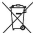
Waste electrical products must not be disposed of with household waste. Please recycle where facilities exist. Check with your local authorities or retailer for recycling advice.

Li-Ion battery This product has been marked with a symbol relating to ‘separate collection’ for all battery packs and battery pack. It will then be recycled or dismantled in order to reduce the impact on the environment. Battery packs can be hazardous for the environment and for human health since they contain hazardous substances.


Do not burn
Batteries may enter water cycle if disposed improperly, which can be hazardous for ecosystem. Do not dispose of waste batteries as unsorted municipal waste.
 | Make sure the battery is removed prior to changing accessories. |
 | WARNING – Beware of blade thrust |
 | Trimming |
NOTE: Before using the tool, read the instruction book carefully.
BEFORE OPERATION:
Assembling the bike handle (See Fig. A)

- Remove the battery pack before assembling the bike handle.
- Place the bike handle(a) into the lower clamp molding(e). Then place the upper clamp molding (b) and clamp screw(c) in order as shown. Finally, tighten the screws(d) to finish the assembly.
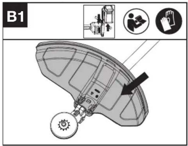
Disassembly and assembly of the safety guard WARNING:
- The battery pack must be remove before assembling or unassembling the safety guard.
- In order to reduce risk of injury and show maximum performance of cutting, the safety guard and cutting attachment must be approved.
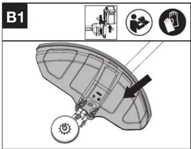
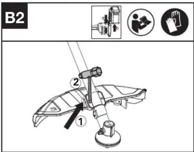
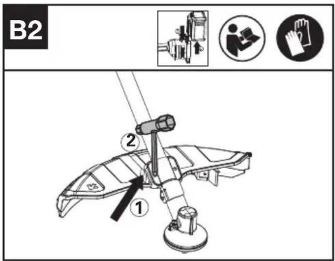
Assembling the safety guard (See Fig B1,B2)
- Place the safety guard into the position until the safety guard is tight against the position.(See Fig B1)
- Tighten the screws with wrench to make sure the safety guard does not move during operation. (See Fig B2)
Removing the safety guard. (See Fig B3)
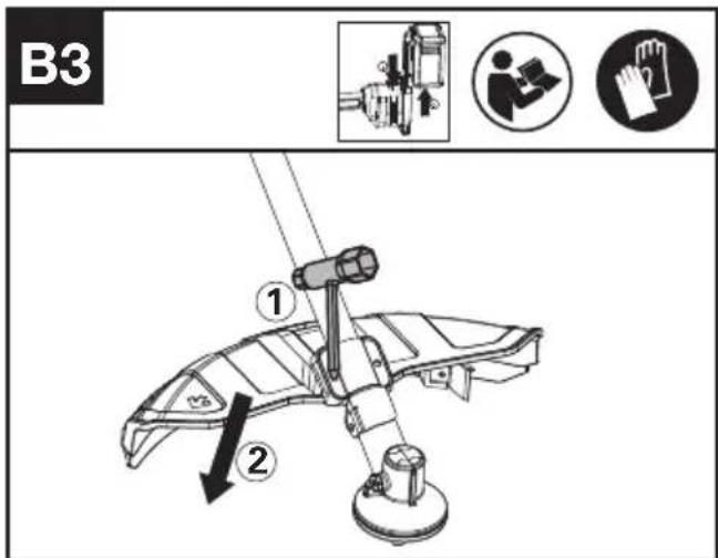
- Remove the screws and release the safety guard.
Disassembly and assembly of the skirt and line-cutting blade
Assembling the skirt and line-cutting blade. (See Fig C1,C2)
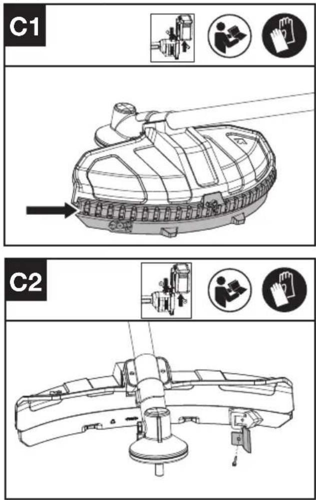
- Slide the skirt along the bottom of the safety guide until the skirt reaches the end of safety guide.
- Place the line-cutting blade into the position of the skirt. Tighten the screws until it is securely positioned in place.
Removing the skirt and line-cutting blade.(See Fig C3)
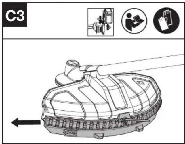
- Insert the stop pin into the hole of the skirt as
shown and remove the skirt along the safety guard.
Disassembly and assembly of the trimmer head
WARNING! A damaged or loose cutting attachment head may vibrate, crack, break or come off the brush cutter, which may result in serious or fatal injury or property damage. Make sure the trimmer head are properly and securely tightened and in good condition before starting work.
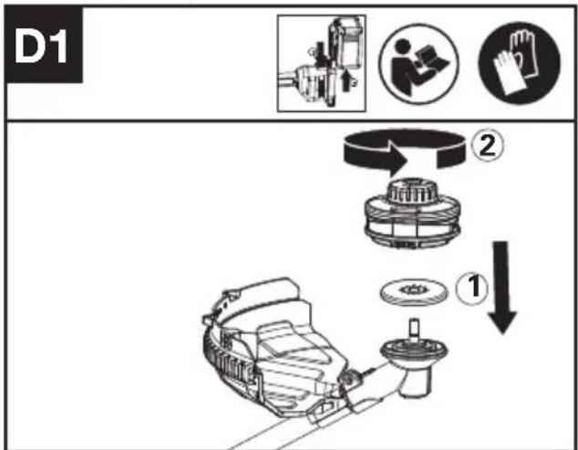
Assembling the trimmer head (See Fig D1)
flowchart
graph TD
    A["Component 1: Gear assembly"] --> B["Step ①"]
    B --> C["Step ②"]
    C --> D["Assembly of gear parts"]
    style A fill:#f9f,stroke:#333
    style D fill:#ccf,stroke:#333
- Position the brush cutter to make it easier for you to operate.
- Place the trimmer head and inner flange in order as shown and rotate the trimmer head in counterclockwise position.
Removing the trimmer head. (See Fig D2)
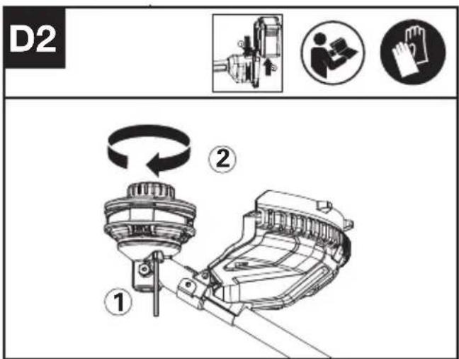
- Insert the stop pin into the gearbox and rotate the trimmer head in clockwise position to remove the trimmer head.
Disassembly and assembly of the 3-teeth blade
Assembling the 3-teeth blade (See Fig E1,E2)
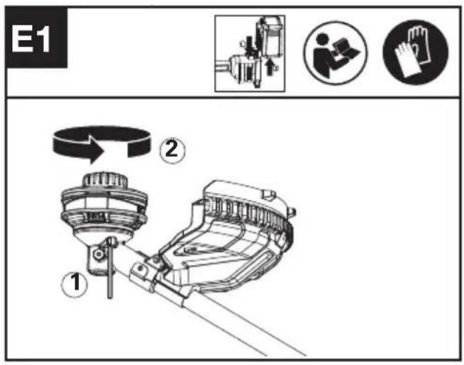
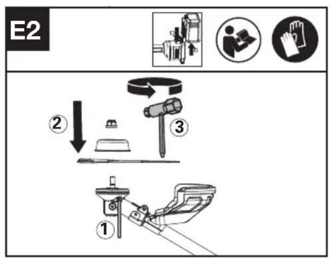
- Position the brush cutter to make it easier for you to operate.
- Insert the stop pin into the gearbox and rotate the trimmer head in clockwise position to remove the trimmer head.
- Place the 3-teeth blade, rider plate, and nut in order and tighten together with allen wrench in counterclockwise position to install 3-teeth blade.
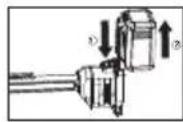
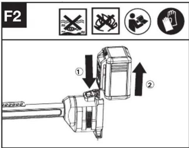
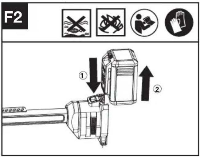
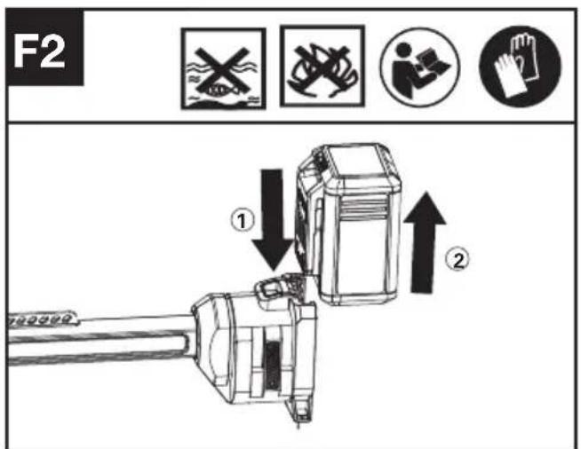
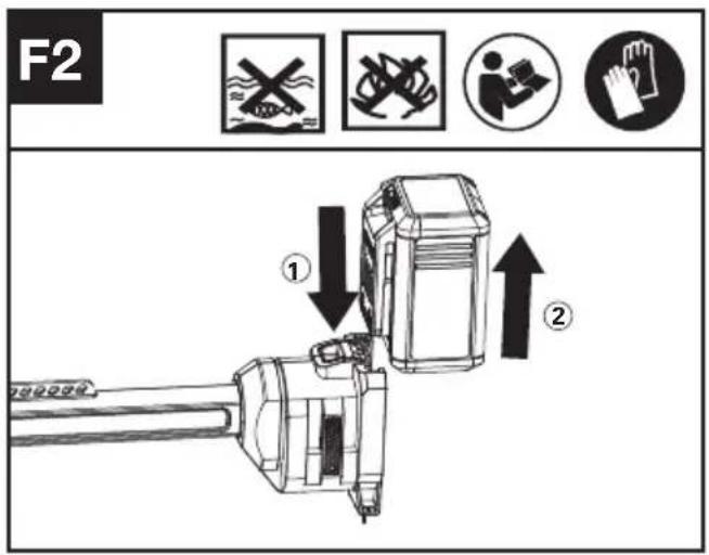
Installing & removing the battery pack (See Fig. F1, F2)
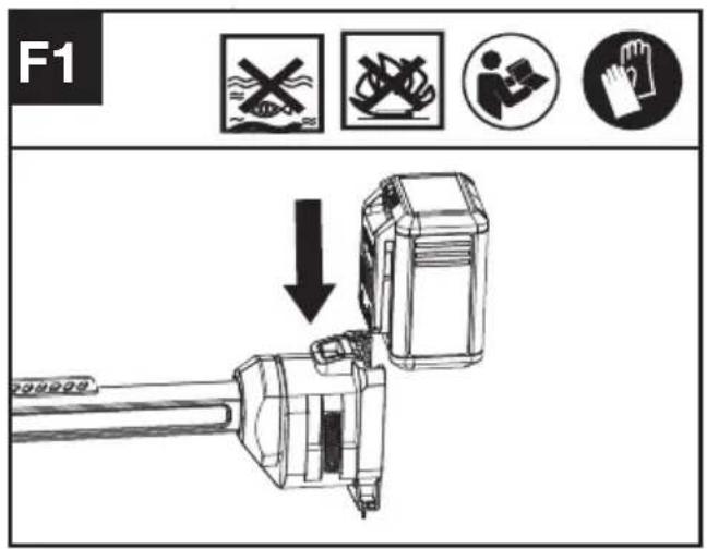
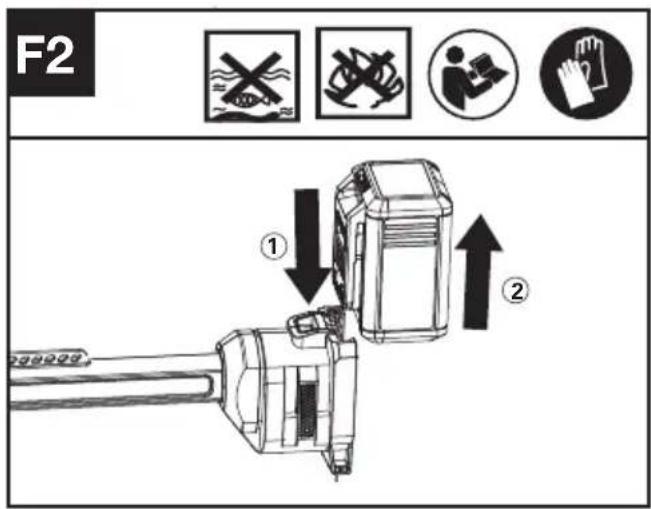
- Slide the battery pack into the battery compartment until you hear a click.
- Press the battery release button to release battery pack from your tool.
Adjusting the bike handle (See Fig. G)
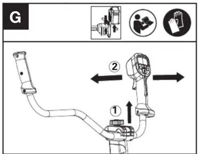
- Loosen the clamp bolt and adjust the bike handle to find the suitable position.(See Fig.G)
- Tighten the clamp bolt until the handle cannot be moved.
Adjusting the harness (See Fig. H)
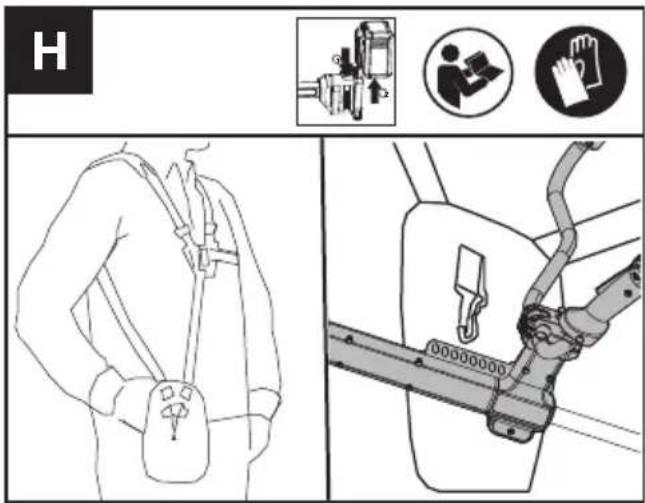
- Adjust the length of harness strap to make it
comfortable during operation while connecting the hip pad to the brush cutter.
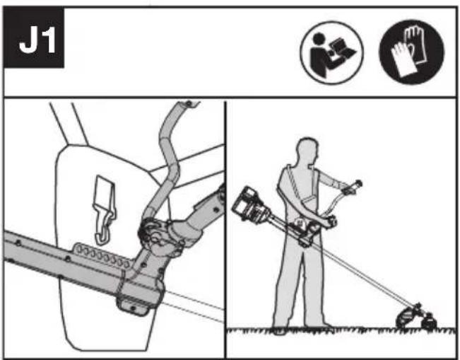
Balancing the Brush cutter (See Fig.1)
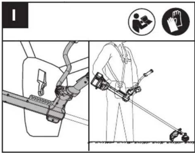
- Put on the harness and connect hip pad to the brush cutter. Let the cutter hang on the harness until it stops moving.(The cutting attachment or the trimmer head should be relaxed over the ground).
Note: Adjust the connection between the hip pad and brush cutter if the brush cutter is not properly balanced.
OPERATION:
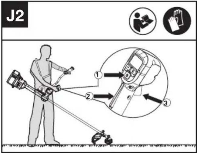
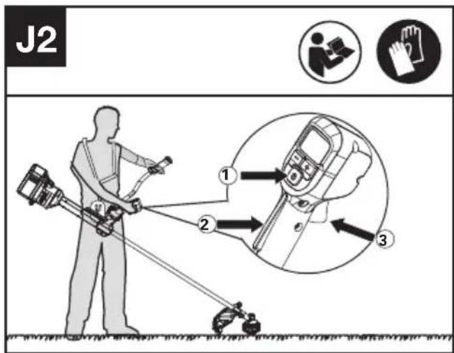
Starting the brush cutter (See Fig. J1, J2)
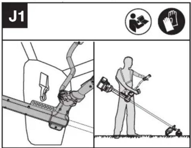
- Connect the hip pad to the brush cutter.
- Hold the brush cutter firmly with your right hand on the control handle – wrap your thumb around the handle. Hold the cutter with your left hand on the auxiliary handle– wrap your thumb around the handle.
- Hold and press the On / Off Switch until the green LED is lit. The green LED shows the power level.
- Press the Operator Presence Switch first, then press the Throttle Trigger to start the machine. The green LED for start/stop indication goes off after 5 seconds and the product needs to be restarted.
NOTE: The Operator Presence Switch is designed to prevent accidental operation. When you press the Operator Presence Switch it releases the Throttle Trigger.
Selecting the speed(See Fig. J3)
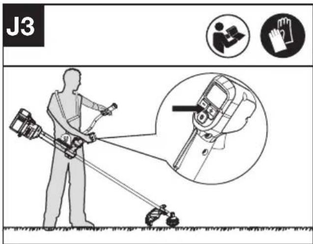
- Power Levels can be selected depending on the application. Use the +/- to control the speed, which is as indicated by the LEDs. The higher the power level, the faster the tool runs.
Stopping the brush cutter
Release the Throttle Trigger to stop the machine.
WARNING! The cutting head continues to rotate after the cutter has been switched off; wait until it has completely stopped then lay down
the tool.
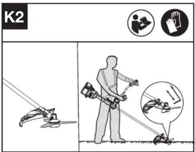
Choose the suitable blade for the application (See Fig. K1, K2)
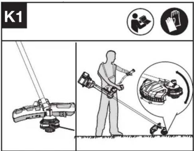
- When working with tirmmer head and skirt, move the brush cutter back and forth on the ground as Fig K1 shown.
- When working with cutting blade, sweep the brush cutter parallel to the ground in front of you. To reduce the risk of kick back, use the left side of the cutting blade.
NOTE
- Use the tip of the cutting line to do trimming; do not force the trimmer head into uncut grass.
- Wire and picket fences may cause extra cutting line wear and breakage. Stone and brick walls, curbs, and wood may wear cutting line rapidly.
- Avoid trees and shrubs. Tree bark, wood moldings, siding, and fence posts can easily be damaged by the cutting line.
- The selected power level affects the battery's runtime. The lower the power level, the longer the runtime. It is recommended to use the lowest power level unless in worse cutting condition.
TRANSPORTATION
Transporting the Brush cutter
- Switch off the brush cutter and remove the
battery.
- When transporting your brush cutter by hand, hold the middle of shaft to make sure that your machine is parallel to the ground.
- When transporting your brush cutter in a vehicle, secure and position it to prevent movement or damage.
Transporting the battery
- Ensure the battery is in a safe condition.
- Use non-conductive packaging when transporting the battery.
- The contained Li-Ion batteries are subject to the dangerous goods legislation requirements.
Transport batteries only when the battery housing is undamaged. Pack up the batteries in such a manner that cannot move around in the packaging.
MAINTENANCE
WARNING! Always remove battery before conducting any maintenance on the brush cutter.
WARNING! Use of wire or metal-reinforced line is not authorized and could be extremely dangerous. Use only the cutting line recommended in this manual, in combination
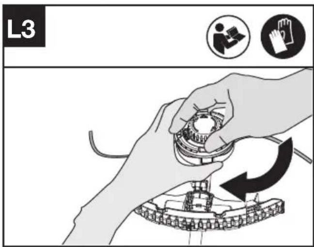
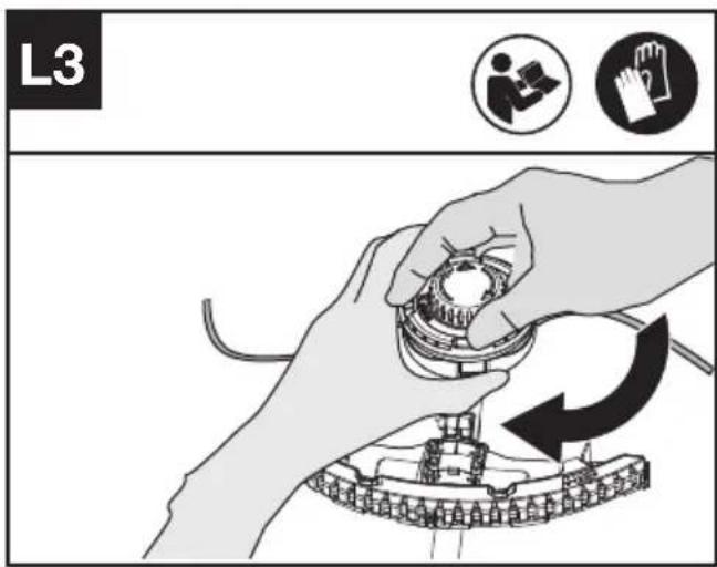
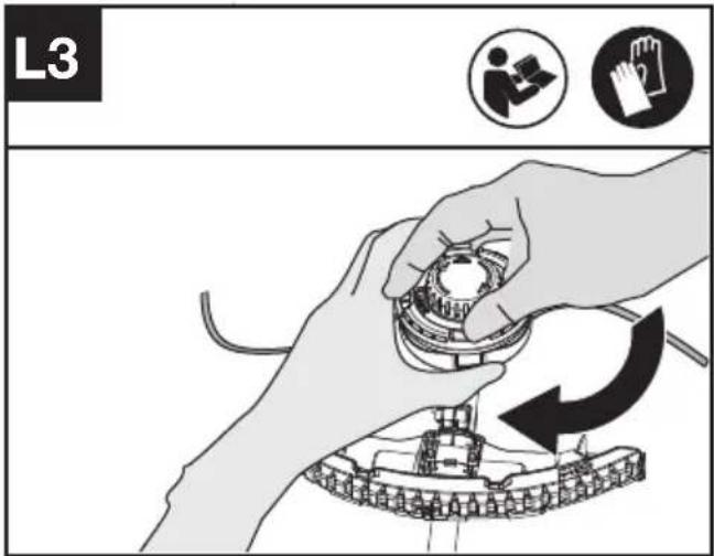
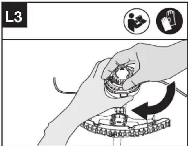
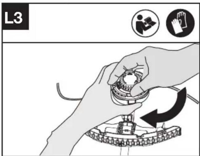
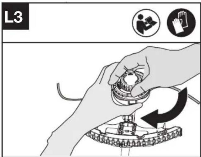
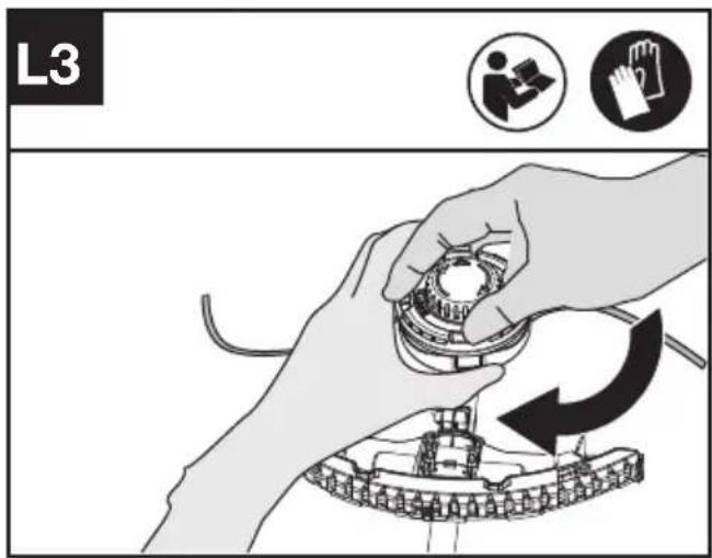
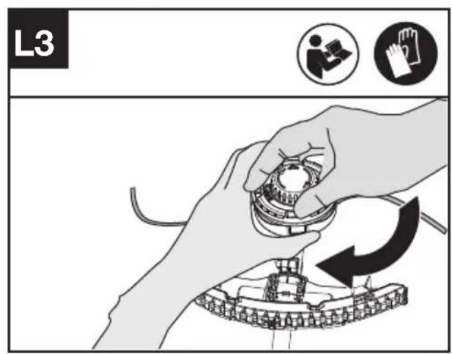
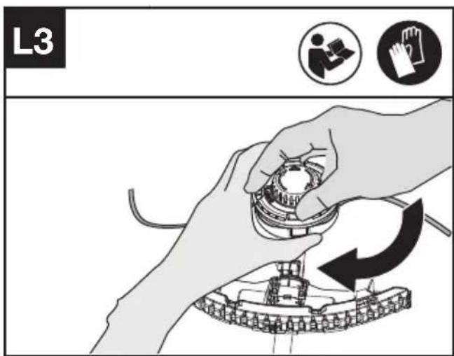
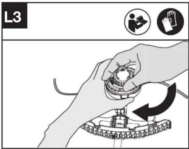
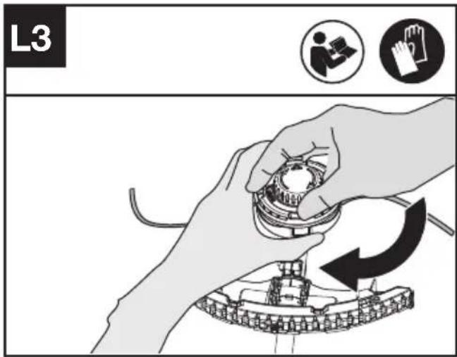
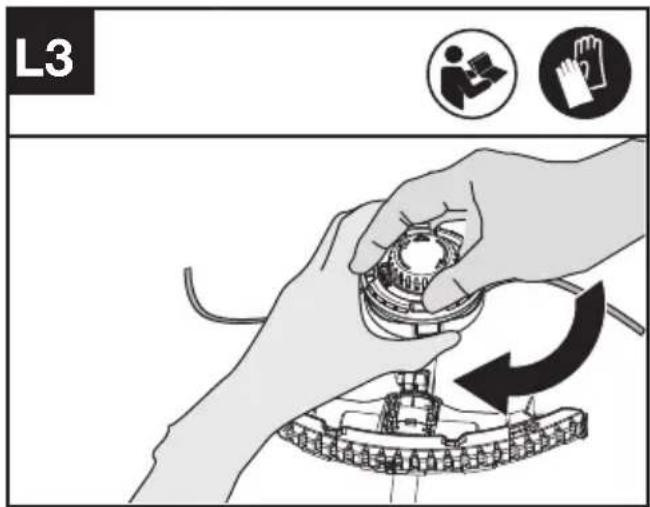
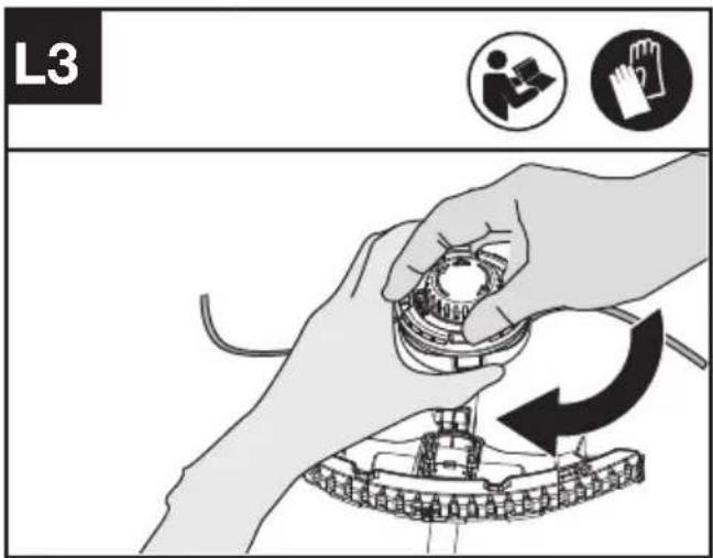
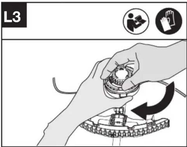
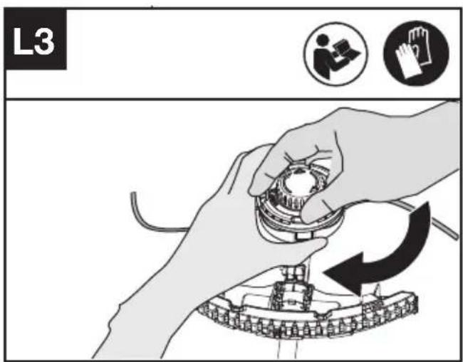
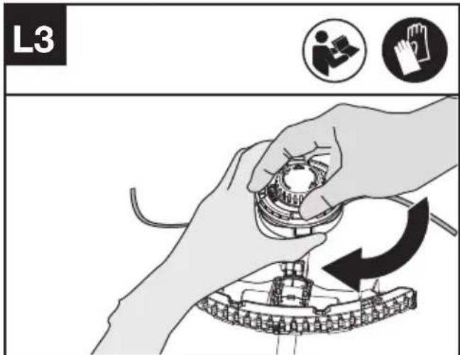
Winding the line (See Fig. L1, L2, L3)
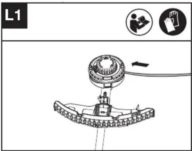
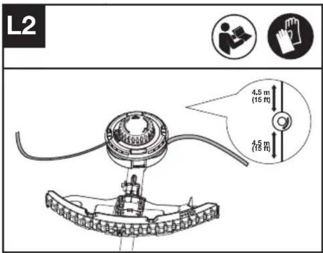
- Insert the replacement line through the eyelet (LINE IN) and feed it through the other side. Ensure both ends of the line are even on each end of the trimmer head (recommended 4.5m) and cut the line. (See Fig. L1,L2)
- Turn the knob clockwise to wind the line around the spool until about 16cm remains on either side. (See Fig. L3)
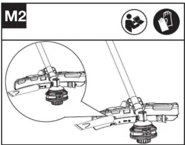
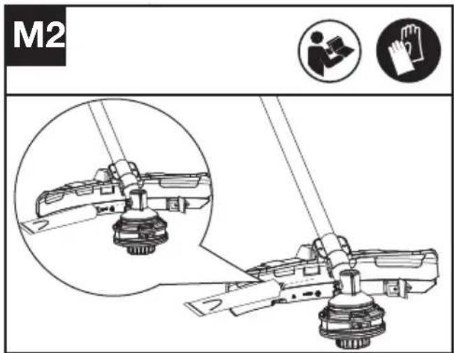
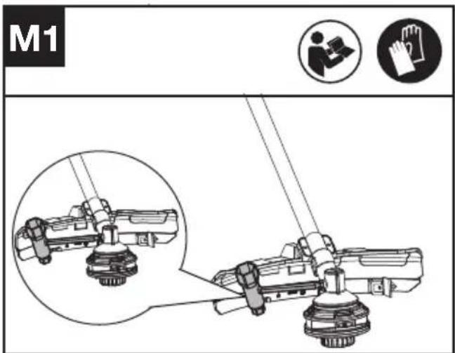
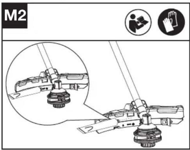
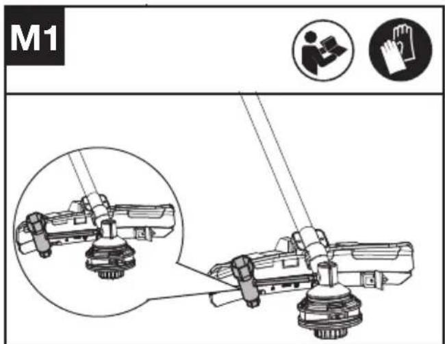
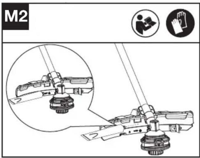
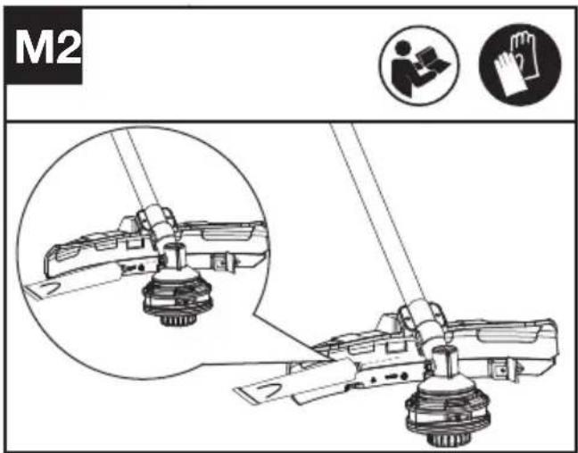
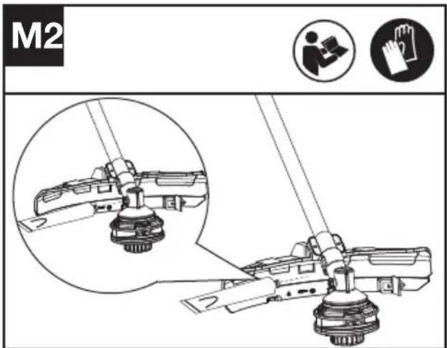
Lubricating the gearbox (See Fig. M1, M2)
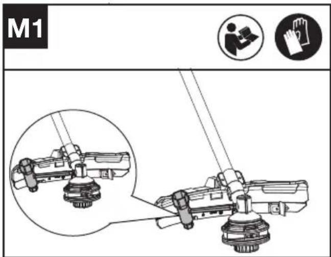
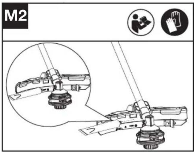
- Remove the screw on the gearbox.
- If there is no grease on the end of the screw, squeeze 5 g of the gear grease into the gear housing.
- Refit and tighten the screw firmly.
- Install the battery and run the brush cutter for 1 minute to ensure the gear is evenly lubricated.
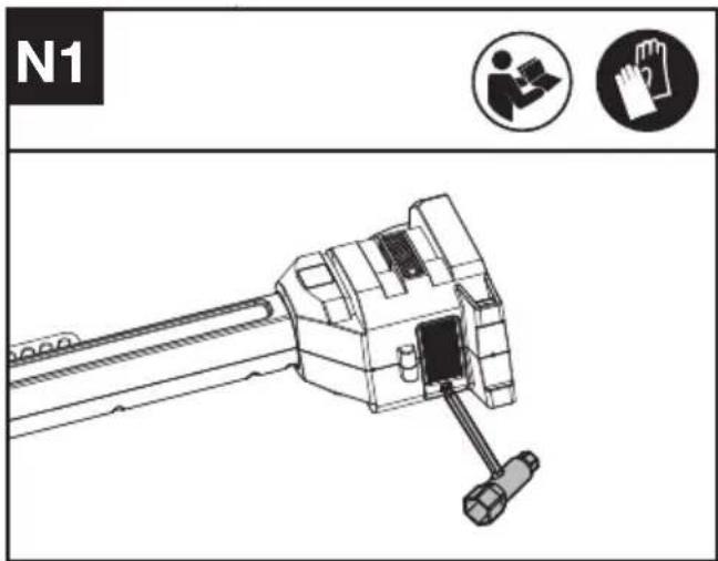
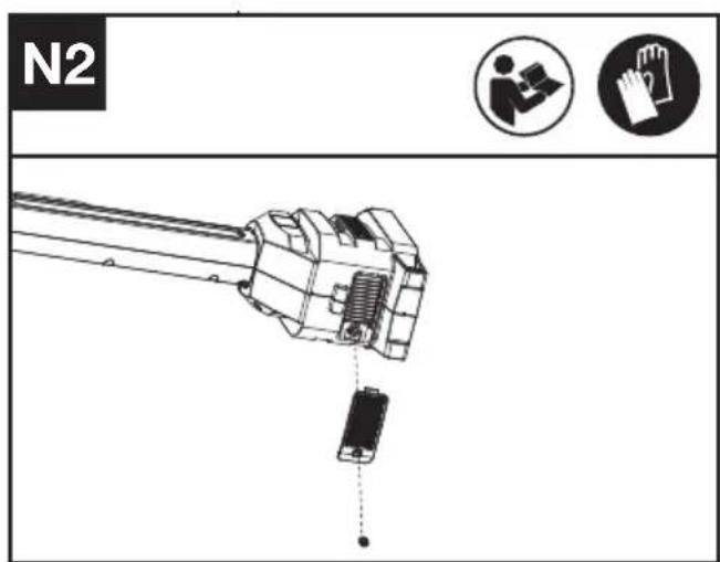
Cleaning the air filter (See Fig. N1, N2)
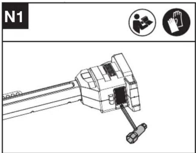
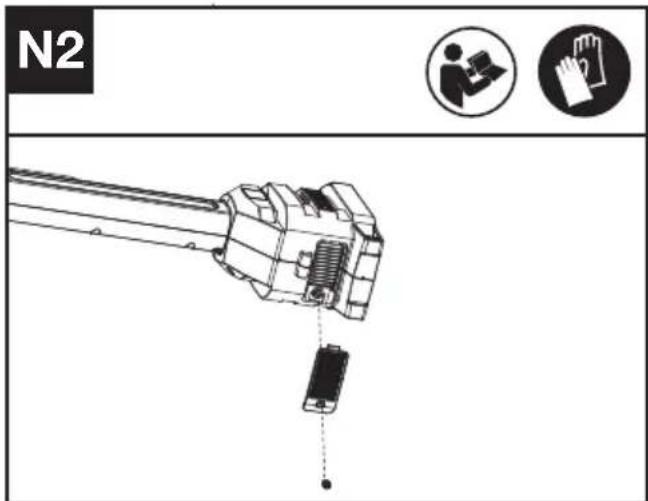
- Clean the area around the air filter. Use a damp cloth or a soft brush.
- Unscrew and remove the air filter.
- Wash the air filter with running water to remove
the dirt.
- Allow the air filter to dry in the air. And then install it in the housing by thightening the screw.
Maintenance intervals
It is recommended to lubricate the gearbox and clean the air filter every 50 hours of operation based on actual usage.
CLEANING
- Switch off the brush cutter and remove the battery.
- Do not use aggressive detergents or solvents. Clean the machine after use with a damp cloth dipped in mild detergent.
- Keep battery connection free of dirt and debris, and clean with a soft and dry brush or cloth.
- Do not spray water onto the motor and electrical components.
- Do not use pressure washer to clean your machine.
STORAGE
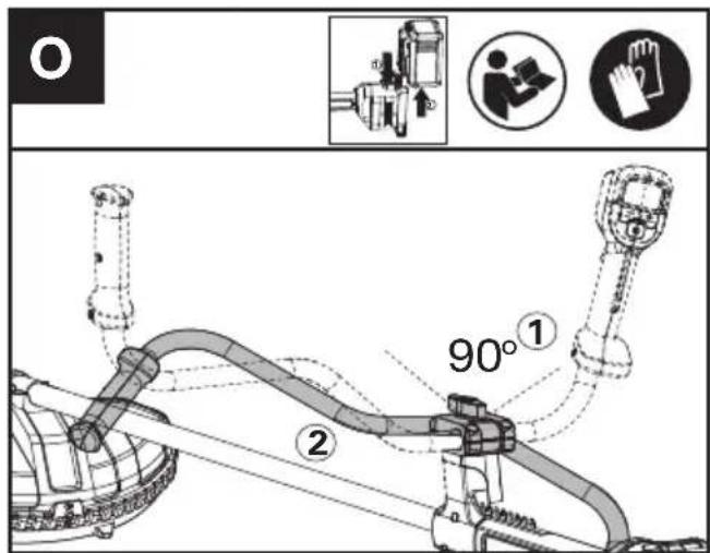
- Remove the battery pack from the brush cutter before storage.
- Loosen the clamp bolt until the bike handle can be moved.
- Rotate the bike handle 90^ in a clockwise position and fold it down.
- Tighten the clamp bolt until the handle cannot be moved.
- Store the brush cutter and the battery in a dry and secure place that is inaccessible to children and other unauthorized people.
Remove the cutting attachment if it will not be used for a long time.
- Store the battery only within a temperature range between 5 °C (41 °F) and 25 °C (77 °F). As an example, do not leave the battery in the car in summer time.
- Once got wet in the rain during operation, the machine and the battery should be dried before storing or charging. Remove the battery and
reinsert it if the machine fails to turn on.
The recommended ambient temperature range for discharging is -20^ 45^(-4^ 113^) .
The recommended ambient temperature range for the charging system during charging is -5^ 45^ ( 23^ 113^ ).
TROUBLESHOOTING
The following table gives problems and actions that you can perform if your machine does not operate correctly.

WARNING: Switch the machine off and remove the battery prior to any troubleshooting.
Brush cutter
| Problems Possible | Causes Corrective Action | |
| Battery indicator LED flashing | Low battery voltage. Charge the battery. |
| Red error LED flashing Overload. The cutting attachment is jammed |
|
|
|
|
|
|
|
|
|
|
|
|
|
|
|
|
|
|
|
|
|
BATTERY
| Problems Possible | Causes Corrective Action | |
| Error LED lit The battery is discharged | Charge the battery. If battery fails to charge, contact your Service Agent. | |
| Temperature issue. Use the battery in surroundings where temperatures are between 5°C and 40°C (41°F to 104°F) for charge; -10°C to 50°C (14°F to 122°F) for discharge. | |
| Others Contact your Service Agent. | |
TECHNICAL DATA
Type Designation: KC170 KC170.X (1-designation of machinery, representative of Cordless brush cutter)
| KC170 KC170.X ** |
| Voltage | 60 V --- MAX *** |
| Cutting speed | 4200 / 5100 / 5900 rpm |
| Cutting Diameter | 42cm |
| Line Diameter | 2.4 / 2.7 mm nylon line |
| Degree of protection | IPX4 |
| Machine Weight (Bare tool) | 5.5 kg |
** X=1-999,A-Z,M1-M9 they are only used for different customers, there are no safety relevant changes between these models.
*** Voltage measured without workload. Initial battery voltage reaches maximum of 60 volts. Nominal voltage is 54 volts.
SUGGESTED BATTERIES AND CHARGERS
| Battery Capacity | Charger Amperage | | |
| KAC804 4.0 Ah | | KAC840 30 A | |
| KAC810(With Backpack Harness) | 11.0 Ah |
We recommend that you purchase your accessories from the same Dealer that sold you the tool. Refer to the accessory packaging for further details. Your Dealer can assist you and offer advice.
EN
TECHNICAL DATA FOR BATTERY PACK (OPTIONAL)
| Frequency bands for Bluetooth 2400-2483.5 MHz | |
| Maximum Output Power for Bluetooth | 8 dBm |
COMBINATIONS OF CUTTING ATTACHMENTS, DEFLECTORS, AND CARRYING SYSTEMS
| Cutting attachment Debris | guard Carrying system | |
| - 4" Trimmer head(Optional, not included)- 5" Trimmer head | - Universal deflector with skirt | - Double shoulder harness- Backpack battery Harness with hip pad |
| - Knife blade - Universal deflector | without skirt |
FOR BRUSH CUTTER
NOISE INFORMATION
| A weighted sound pressure L | _pA = 80 dB(A) |
| K_pA | 3 dB(A) |
| A weighted sound power L | _wA = 91.7 dB(A) |
| K_wA | 3 dB(A) |
| Wear ear protection. |
VIBRATION INFORMATION
| Typical weighted vibration a | _h = 3.7 m/s^2 |
| Uncertainty K = 1.5 m/s^2 | |
FOR GRASS TRIMMER
NOISE INFORMATION
| A weighted sound pressure L | _pA =80.2 dB(A) |
| K_pA | 3 dB(A) |
| A weighted sound power L | _wA =92.9 dB(A) |
| K_wA | 3 dB(A) |
| Wear ear protection |
VIBRATION INFORMATION
| Typical weighted vibration a | _h = 4.9 m/s^2 |
| Uncertainty K = 1.5 m/s^2 | |
WARNING: The vibration emission value during actual use of the power tool can differ from the declared value depending on the ways in which the tool is used dependant on the following examples and other variations on how the tool is used:
How the tool is used and the materials being cut or drilled.
The tool being in good condition and well maintained. Using the correct accessory for the tool and ensuring it is sharp and in good condition.
The tightness of the grip on the handles and if any anti vibration accessories are used.
And the tool is being used as intended by its design and these instructions.
This tool may cause hand-arm vibration syndrome if its use is not adequately managed.
WARNING: To be accurate, an estimation of exposure level in the actual conditions of use should also take account of all parts of the operating cycle such as the times when the tool is switched off
and when it is running idle but not actually doing the job. This may significantly reduce the exposure level over the total working period.
Helping to minimise your vibration exposure risk.
ALWAYS use sharp chisels, drills and blades
Maintain this tool in accordance with these instructions and keep well lubricated (where appropriate)
If the tool is to be used regularly then invest in anti vibration accessories.
Avoid using tools in temperatures of 10^0 C or less
Plan your work schedule to spread any high vibration tool use across a number of days.
ENVIRONMENTAL PROTECTION

Waste electrical products must not be disposed of with household waste. Please recycle where facilities exist. Check with your
local authorities or retailer for recycling advice.
We,
Positec Germany GmbH
Postfach 32 02 16, 50796 Cologne, Germany
On behalf of Positec declare that the product
Description Cordless Grass Brush Cutter
Type KC170 KC170.X (1-designation of machinery, representative of Cordless Grass Trimmer/Brush cutter)
Function cutting weeds, scrub, brush, and similar vegetation
Complies with the following Directives:
2006/42/EC, 2014/30/EU, 2011/65/EU & (EU)
2015/863, 2000/14/EC amended by 2005/88/EC
For Brush cutter
2000/14/EC amended by 2005/88/EC:
- Conformity Assessment Procedure as per Annex VI
- Measured Sound Power Level 91.7 dB (A)
- Declared Guaranteed Sound Power Level 92 dB (A)
For Grass trimmer
2000/14/EC amended by 2005/88/EC:
- Conformity Assessment Procedure as per Annex VI
- Measured Sound Power Level 92.9 dB (A)
- Declared Guaranteed Sound Power Level 96 dB (A)
The notified body involved
Standards conform to
EN 62841-1, FprEN IEC
62841-4-4:2020+FprAA:2021-02, EN 62233, EN
ISO 3744, EN IEC 55014-1, EN IEC 55014-2, EN
300328, EN 301489-1/-17, EN 50663
The person authorized to compile the technical file,
Name Marcel Filz
Address Positec Germany GmbH
Postfach 32 02 16, 50796 Cologne, Germany


2023/01/10
Allen Ding
Deputy Chief Engineer, Testing & Certification
Positec Technology (China) Co., Ltd
18, Dongwang Road, Suzhou Industrial
Park, Jiangsu 215123, P. R. China
We,
Positec (UK & Ireland) Ltd
PO Box 6242, Newbury, RG14 9LT, UK
On behalf of Positec declare that the product
Description Cordless Grass Brush Cutter&Grass trimmer
Type KC170 KC170.X (1-designation of machinery, representative of Cordless Grass Trimmer/Brush cutter)
Function cutting weeds, scrub, brush, and similar vegetation
Complies with the following regulations:
Supply of Machinery (Safety) Regulations 2008
Electromagnetic Compatibility Regulations 2016
The Restriction of the Use of Certain Hazardous Substances in Electrical and Electronic Equipment Regulations
Noise Emission in the Environment by Equipment for Use Outdoors Regulations
For Brush cutter
- Conformity Assessment Procedure as per SCHEDULE 9
- Measured Sound Power Level 91.7 dB (A)
- Declared Guaranteed Sound Power Level 92 dB (A)
For Grass trimmer
- Conformity Assessment Procedure as per SCHEDULE 9
- Measured Sound Power Level 92.9 dB (A)
- Declared Guaranteed Sound Power Level 96 dB (A)
The notified body involved
Standards conform to
BS EN 62841-1, FprBS EN IEC
62841-4-4:2020+FprAA:2021-02, BS EN 62233,
BS EN ISO 3744, BS EN IEC 55014-1, BS EN IEC
55014-2, BS EN 300328, BS EN 301489-1/-17, BS EN 50663
The person authorized to compile the technical file,
Name Jim Kirkwood
Address Positec (UK & Ireland) Ltd,
PO Box 6242, Newbury, RG14 9LT, UK


2023/01/10
Allen Ding
Deputy Chief Engineer, Testing & Certification
Positec Technology (China) Co., Ltd
18, Dongwang Road, Suzhou Industrial
Park, Jiangsu 215123, P. R. China
INHALTSVERZEICHNIS
Einführung......21
Komponenten....23
KOMPONENTEN
18, Dongwang Road, Suzhou Industrial
Park, Jiangsu 215123, P. R. China
SOMMAIRE
Introduction......40
LISTE DES COMPOSANTS
- BLOC DE BATTERIE *
- BOUTON DE DÉVERROUILLAGE DE LA BATTERIE
- POIGNÉE DE TYPE GUIDON
- POIGNÉE
- BOULON DE BLOCAGE
- ARBRE
- BOUTON MARCHE/ARRÊT
- GÂCHETTE D'ACCÉLÉRATION
- BOUTON DE COMMANDE
- COMMUTATEUR DE PRÉSENCE D'OPÉRATEUR
- ÉCRAN
- ASSEMBLAGE DE LA PROTECTION
- LAME DE COUPE-LIGNE
- TÊTE DE COUPE
- BOUCLE DE HARNAIS
- PROTÈGE-HANCHE
- LAME À 3 DENTS
- JUPE
- ÉCROU
- CLÉ HEXAGONALE
- GOUPILLE D'ARRÊT
- CAPOT DE FIXATION DE LA LAME
- FOURREAU DE LAME
NOTICE ORIGINALE AVERTISSEMENTS DE SÉCURITÉ SÉCURITÉ DU PRODUIT AVERTISSEMENTS GÉNÉRAUX DE SÉCURITÉ POUR L'OUTIL

18, Dongwang Road, Suzhou Industrial
Park, Jiangsu 215123, P. R. China
INDICE
Introduzione....59
ELEMENTI DELL'APPARECCHIO
- PACCO BATTERIA*
- PULSANTE DI RILASCIO DELLA BATTERIA
- MANUBRIO
- IMPUGNATURA
- BULLONE DI FISSAGGIO
- ASTA
- PULSANTE ON/OFF
- GRILLETTO DELL'ACCELERATORE
- PULSANTE DI CONTROLLO
- INTERRUTTORE DI PRESENZA DELL'OPERATORE
- SCHERMO
- MONTAGGIO DELLA PROTEZIONE
- LAMA TAGLIALINEA
- TESTINA TAGLIABORDI
- FIBBIA PER IMBRACATURA
- CUSCINETTO PER FIANCHI
- LAMA A 3 DENTI
- RIVESTIMENTO
- DADO
20.CHIAVE A BRUGOLA
- PERNO DI ARRESTO
- COPERTURA FISSA DELLA LAMA
- GUAINA DELLA LAMA
ISTRUZIONI ORIGINALI AVVISI PER LA SICUREZZAGENERALI PER LA SICUREZZA DEGLI UTENSILI A MOTORE

flowchart
graph TD
    A["Component 1: Hand gesture"] --> B["Assembly Gear"]
    B --> C["Car with Component 2"]
    C --> D["Assembly Gear with Switch"]
    D --> E["Assembly Gear with Cover"]
    style A fill:#f9f,stroke:#333
    style E fill:#bbf,stroke:#333
18, Dongwang Road, Suzhou Industrial
Park, Jiangsu 215123, P. R. China
ÍNDICE
Introducción....78
Lista de componentes....80
18, Dongwang Road, Suzhou Industrial
Park, Jiangsu 215123, P. R. China
ÍNDICE
Introdução....97
Lista de componentes....99
18, Dongwang Road, Suzhou Industrial
Park, Jiangsu 215123, P. R. China
INHOUDSOPGAVE
Inleiding....116
DRIE SNELHEIDSINSTELLINGEN
-
ACCUPACK*
-
ACCU-ONTGRENDELKNOP
-
FIETSHANDVAT
-
HANDGREEP
-
KLEMBOUT
-
SCHACHT
-
AAN/UIT-KNOP
-
GASHENDEL
-
REGELKNOP
-
DODEMANSKNOP
-
SCHERM
-
BESCHERMKAP
-
DRAADSNIJMES
-
TRIMMERKOP
-
HARNASGESP
-
HEUPKUSSEN
-
3-TANDIG MES
-
SPATSCHERM
-
MOER
-
INBUSSLEUTEL
-
BORGPIN
-
MES VASTE BESCHERMING
-
MESSCHEDE
VEILIGHEIDSWAARSCHUWINGEN
VOOR BOSMAAIERS EN GRASTRIMMERS
flowchart
graph TD
    A["1: Seat"] --> B["2: Down arrow"]
    B --> C["3: Handwashing"]
    C --> D["4: Cover cup"]
    D --> E["5: Cover cup with hand gesture"]
    E --> F["6: Handwashing with hand gesture icon"]
    F --> G["7: Handwashing with hand gesture icon icon"]

18, Dongwang Road, Suzhou Industrial
Park, Jiangsu 215123, P. R. China
TARTALOMJEGYZÉK
Bevezető....135
flowchart
graph TD
    A["Component Identification"] --> B["Assembly"]
    B --> C{Mechanical Shift}
    C -->|①| D["Assembly Equipment"]
    C -->|②| E["Carriage Rotation"]
    E --> F["Hand gestures and weights"]
18, Dongwang Road, Suzhou Industrial
Park, Jiangsu 215123, P. R. China
CUPRINS
Introducere....154
LISTA DE COMPONENTE
- ACUMULATOR*
- BUTON DE ELIBERARE A ACUMULATORULUI
- GHIDON
- ZONĂ DE PRINDERE MANUALĂ
- BOLT DE PRINDERE
- AX
- BUTON DE PORNIRE/OPRIRE
- BUTON DE ACCELERATIE
- BUTON DE CONTROL
- COMUTATOR PENTRU PREZENTA UTILIZATORULUI
- ECRAN
- ANSAMBLU DE PROTECTIE
- LAMĂ PENTRU TĂIERE CU FIR
- CAP DE TĂIERE
- CATARAMĂ PENTRU HAM
- PAD PENTRU SOLD
- LAMĂ CU 3 DINTI
- SORT
- PIULITĂ
- IMBUS
- STIFT DE OPRIRE
- CAPAC FIX PENTRU LAMĂ
23.APĂRĂTOAREA PENTRU LAMĂ
INSTRUCTIUNI ORIGINALE SECURITATEA PRODUSULUI AVERTISMENTE GENERALE DE SIGURANTĂ PENTRU UNELTE ELECTRICE

flowchart
graph TD
    A["Component Identification"] --> B["Assembly"]
    B --> C{Mechanical Shift}
    C -->|①| D["Assembly Equipment"]
    C -->|②| E["Car Wheel"]
    E --> F["Hand gestures and weights"]
Adresă Positec Germany GmbH
Postfach 32 02 16, 50796 Cologne,
Germany

2023/01/10
Allen Ding
Adjunct Inginer şef, Testare si certificare
Positec Technology (China) Co., Ltd
18, Dongwang Road, Suzhou Industrial
Park, Jiangsu 215123, P. R. China
SPIS TREŚCI
Wprowadzenie....173
LISTA KOMPONENTÓW
flowchart
graph TD
    A["Step 1: Hand press"] --> B["Step 2: Down arrow"]
    B --> C["Step 3: Screw with hammer"]
    C --> D["Step 4: Presser with hand icon"]
    D --> E["Image: hand gesture, toolbar, worker, gloves"]
18, Dongwang Road, Suzhou Industrial
Park, Jiangsu 215123, P. R. China
OBSAH
Úvod....192
SEZNAM KOMPONENT
- AKUMULÁTOR*
- TLAČÍTKO UVOLNĚNÍ BATERIE
- RÍDÍTKA
- RUKOJEŤ
- UPÍNACÍ ŠROUB
- HŘÍDEL
- HLAVNÍ VYPÍNAČ
- SPOUŠT
- OVLÁDACÍ TLAČÍTKO
- SPÍNAČ PŘÍTOMNOSTI OBSLUHY
- OBRAZOVKA
- SESTAVA KRYTU
- SEKACÍ NŮŽ
- SEKACÍ HLAVA
- SPONA POSTROJE
- KYČELNÍ PODLOŽKA
- TROJZUBÝ NŮŽ
- OCHRANNÝ LEM
- MATICE
- IMBUSOVÝ KLÍČ
- ZASTAVOVACÍ PIN
- PEVNÝ KRYT NOŽE
23.POUZDRO ČEPELE
PŮVODNÍ NÁVOD K POUŽÍVÁNÍ BEZPEČNOST VÝROBKU OBECNÁ BEZPEČNOSTNÍ UPOZORNĚNÍ PRO ELEKTRICKÉ NÁSTROJE
Park, Jiangsu 215123, P. R. China
MY,
Positec Germany GmbH
Postfach 32 02 16, 50796 Cologne, Germany
18, Dongwang Road, Suzhou Industrial
OBSAH
Úvod....211
ZOZNAM SÚČASTÍ
- BATÉRIOVÝ BLOK *
- TLAČIDLO NA UVOL'NENIE BATÉRIE
- BICYKLOVÉ RIADIDLO
- RUKOVÄT
- UPÍNACIA SKRUTKA
- HRIADEL'
- TLAČIDLO ZAP/VYP
- PÁKA OVLÁDANIA
- OVLÁDACIE TLAČIDLO
- SPÍNAČ PRÍTOMNOSTI OBSLUHY
- OBRAZOVKA
- ZOSTAVA OCHRANNÉHO KRYTU
- ČEPEL' NA ODREZANIE LANKA
- VYŽÍNACIA HLAVICA
- PRACKA POSTROJA
- BEDROVÁ PODLOŽKA
- 3-ZUBOVÁ ČEPEL'
- OBRUBA
- MATICA
- IMBUSOVÝ KLÚČ
- DORAZOVÝ KOLÍK
- PEVNÝ OCHRANNÝ KRYT ČEPELE
23.PLÁŠŤ ČEPELE
PÔVODNÝ NÁVOD NA POUŽITIE BEZPEČNOSTŠT VÝROBKU VŠEOBECNÉ BEZPEČNOSTNÉ UPOZORNENIA
flowchart
graph TD
    A["Component Identification"] --> B["Assembly"]
    B --> C{Mechanical Shift}
    C -->|①| D["Assembly Equipment"]
    C -->|②| E["Carriage Rotation"]
    E --> F["Hand gestures and weights"]
18, Dongwang Road, Suzhou Industrial
Park, Jiangsu 215123, P. R. China
KAZALO VSEBINE
Uvod....230
Sestavni deli....232
Varnost izdelka....233
Sestavljanje in delovanje....237
Transport....242
Vzdrževanje....242
Čiščenje....243
Shranjevanje....243
SESTAVNI DELI
- BATERIJSKI SKLOP*
- GUMB ZA SPROSTITEV BATERIJE
- KOLESARSKI ROČAJ
- OPRIJEM
- OBJEMNI VIJAK
- GRED
- GUMB ZA VKLOP/IZKLOP
- SPROŽILEC PLINA
- KONTROLNI GUMB
- STIKALO ZA PRISOTNOST UPRAVLJAVCA
- ZASLON
- SKLOP VAROVALA
- REZILO ZA REZANJE NITKE
- GLAVA OBREZOVALNIKA
- ZAPONKA ZA PAS
- BOČNA BLAZINICA
- 3-ZOBO REZILO
- OBROBA
- MATICA
20.INBUS KLJUČ
21.OMEJEVALNI ZATIČ
22.FIKSNI POKROV REZILA
- TULEC ZA REZILO
IZVIRNA NAVODILA VARNOST IZDELKA SPLOŠNA VARNOSTNA OPOZORILA

- Nadenite jermen in povežite bočno blazinico z motorno koso. Kosa naj visi na jermenu, dokler se ne ustavi. (Rezilni nastavek ali glava obrezovalnika morata biti sproščena nad tlemi). Opomba: prilagodite povezavo med bočno blazinico in motorno koso, će motorna kosa ni pravilno uravnotežena.
DELOVANJE:
Zagon motorne kose (Glej sliki J1, J2)
- Priključite bočno blazinico na motorno koso.
- Z desno roko trdno držite motorno koso za krmilni ročaj – s palcem zaobjemite ročaj. Z levo roko držite motorno koso za pomožni ročaj – s palcem zaobjemite ročaj.
- Držite in pritisnite stikalo za vklop/izklop, dokler ne zasveti zelena LED lučka. Zelena LED lučka prikazuje raven energije.
- Najprej pritisnite stikalo za prisotnost upravljavca, nato pritisnite sprožilec plina, da zaženete stroj. Zelena LED lučka za indikacijo start/stop ugasne po 5 sekundah in izdelek je treba znova zagnati.

Mazanje menjalnika (glej sliki M1, M2)
- Odstranite vijake na menjalniku.
- Če na koncu vijaka ni maziva za stožčasti zobnik, stisnite 5 g maziva za prestavo v ohišje prestave.
- Ponovno namestite in trdno privijte vijake.
- Namestite baterijo in zaženite obrezovalnik za 1 minuto, da zagotovite enakomerno mazanje prestave.
18, Dongwang Road, Suzhou Industrial
Park, Jiangsu 215123, P. R. China
SADRŽAJ
Uvod....248
Popis komponenti....250
Sigurnost proizvoda....251
Sastavljanje i rad....255
PRIJEVOZ....260
Održavanje....260
Čišćenje....261
Skladištenje....261
Otklanjanje poteškoća....262
Tehnički podaci....263
HR
Zaštita okoliša....264
Izjava o sukladnosti....265
UVOD
Poštovani,
POPIS KOMPONENTI
- BATERIJSKI MODUL*
- GUMB ZA OTPUŠTANJE BATERIJE
- UPRAVLJAČKA RUČKA
- DRŠKA ZA RUKU
- STEZNI VIJAK
- OSOVINA
- GUMB ZA UKLJUČIVANJE/ISKLJUČIVANJE
- AKTIVATOR GASA
- UPRAVLJAČKI GUMB
- PREKIDAČ PRISUTNOSTI RUKOVATELJA
- ZASLON
- SKLOP ŠTITNIKA
- NOŽ ZA REZANJE NITI
- GLAVA TRIMERA
- KOPČA ZA POJAS
- JASTUČIĆ ZA BOK
- NOŽ S 3 ZUBA
- RUB
- MATICA
- IMBUS KLJUČ
- GRANIČNI ZATIK
- FIKSNI POKLOPAC NOŽA
- POKLOPAC OŠTRICE
ORIGINALNE UPUTE ZA RAD SIGURNOST PROIZVODA UOBIČAJENA SIGURNOSNA UPOZORENJA ZA ELEKTRIČNE ALATE

UPOZORENJE Pročitajte sva sigurnosna upozorenja, upute, ilustracije i specifikacije koje se isporučuju s ovim električnim alatom. Nepoštivanje dolje navedenih uputa može uzrokovati električni udar, požar i/ili ozbiljne ozljede.
- Prije sastavljanja upravljačke ručke uklonite baterijski komplet.
- Postavite upravljačku ručku (a) u donji stezni kalup (e). Zatim postavite gornji stezni kalup (b) i stezni vijak (c) prema prikazanom redoslijedu. Na kraju, zategnite vijke (d) kako biste dovršili sklapanje.
Rastavljanje i sastavljanje sigurnosnog štitnika
UPOZORENJE:
- Prije sastavljanja ili rastavljanja sigurnosnog štitnika baterijski modul mora se ukloniti.
- Kako bi se smanjio rizik od ozljeda i pokazao maksimalni učinak rezanja, sigurnosni štitnik i rezni nastavak moraju biti postavljeni.
Sastavljanje sigurnosnog štitnika (vidi sliku B1, B2)
flowchart
graph TD
    A["1: Seat"] --> B["2: Down"]
    B --> C["3: Gavel with hammer"]
    C --> D["4: Cover with pencil"]
    D --> E["5: Handwashing Icon"]
    E --> F["6: Hand with glove icon"]
- Stavite pojas i spojite jastučić za bok na rezač grmlja. Ostavite rezač da visi na pojasu dok se ne prestane naginjati. (Nastavak za rezanje ili glava trimera trebaju biti opušteni u odnosu na tlo). Napomena: Ako rezač grmlja nije pravilno uravnotežen podesite spoj između jastučića za bok i rezača grmlja.
RAD:
Pokretanje rezača grmlja (vidi sl. J1, J2)
- Umetnite zamjensku nit kroz ušicu (nit unutra) i provucite ju kroz vanjsku ušicu. Uvjerite se da su oba kraja niti jednaka s obje strane glave trimera (preporučeno 4.5 m i odrežite nit. (Vidi sl. L1, L2)
- Okrenite kotačić u smjeru kazaljke na satu kako biste namotali nit oko kalema dok ne ostane oko 16 cm s obje strane. (Vidi sl. L3)
Podmazivanje reduktora (vidi sl. M1, M2)
- Uklonite vijak s reduktora.
- Ako na kraju vijka nema masti za konusne zupčanike, istisnite 5 g masti za zupčanike u kućište zupčanika.
- Vratite vijak i zategnite ga.
- Umetnite bateriju i upalite trimer na 1 minutu kako biste se uvjerili da je zupčanik ravnomjerno podmazan.
Čišćenje filtra zraka (vidi sl. N1, N2)
Oznaka tipa: KC170 KC170.X (1-designation of machinery, representative of Cordless Grass Trimmer/Brush cutter)
Funkcija rezanja korova, grmlja, šikara i sličnog raslinja
18, Dongwang Road, Suzhou Industrial
Park, Jiangsu 215123, P. R. China
INDHOLDSFORTEGNELSE
Introduktion....266
flowchart
graph TD
    A["Component Identification"] --> B["Assembly"]
    B --> C{Mechanical Shift}
    C -->|①| D["Assembly Equipment"]
    C -->|②| E["Carriage Rotation"]
    E --> F["Hand gestures and weights"]
flowchart
graph TD
    A["1: Toilet"] --> B["2: Handwashing"]
    B --> C["3: Hammering"]
    C --> D["4: Handwashing with hand gesture"]
    D --> E["5: Handwashing with hand gesture"]
    E --> F["6: Handwashing with hand gesture"]
    F --> G["7: Handwashing with hand gesture"]
    G --> H["8: Handwashing with hand gesture"]
    H --> I["9: Handwashing with hand gesture"]
    I --> J["10: Handwashing with hand gesture"]
- Use the tip of the cutting line to do trimming; do not force the trimmer head into uncut grass.
- Wire and picket fences may cause extra cutting line wear and breakage. Stone and brick walls, curbs, and wood may wear cutting line rapidly.
- Avoid trees and shrubs. Tree bark, wood moldings, siding, and fence posts can easily be damaged by the cutting line.
- The selected power level affects the battery's runtime. The lower the power level, the longer the runtime. It is recommended to use the lowest power level unless in worse cutting condition.
TRANSPORT
Transport af buskrydderen
Type KC170 KC170.X (1-designation of machinery, representative of Cordless Grass Trimmer/Brush cutter)
18, Dongwang Road, Suzhou Industrial
Park, Jiangsu 215123, P. R. China
SISÄLLYSLUETTELO
Johdanto....284
Komponenttiluettelo....286
KOMPONENTTILUETTELO
- AKKU*
- AKUN VAPAUTUSPAINIKE
- ETUKAHVA
- OTEKAHVA
- KIINNITYSRUUVI
- VARI SI
- ON/OFF-VIRTAKYTKIN
- KAASULIIPAISIN
- OHJAUSPAINIKE
- KÄYTTÄJÄN LÄSNÄOLOKYTKIN
- NÄYTTÖ
- SUOJUS
- SIIMAN LEIKKUUTERÄ
- TRIMMERIPÄÄ
- VALJAAT
- LONKKAPEHMUSTE
- 3-LAPAINEN RUOHOTERÄ
- HELMA
- MUTTERI
- KUUSIOAVAIN
- PYSÄYTYSTAPPI
- TERÄN KIINNITYSMUTTERIN TULPPA
- TERÄSUOJA
18, Dongwang Road, Suzhou Industrial
Park, Jiangsu 215123, P. R. China
INNHOLDFORTEGNELSE
Introduksjon....302
Komponentliste....304
Produktsikkerhet....305
Transportation....313
Vedlikehold....314
Rengjøring....315
Lagring....315
Feilsøking....316
NOR
APPARATELEMENTER
-
BATTERIPAKKE*
-
UTL∅SERKNAPP FOR BATTERI
-
STYREHÅNDTAK
-
HÅNDGREP
-
KLEMMEBOLT
-
SKAFT
-
PÅ/AV-KNAPP
-
GASSBRYTER
-
KONTROLLKNAPP
-
BRYTER FOR OPERAT∅RTILSTEDEVÆRELSE
-
SKJERM
-
VERNMONTERING
-
STRENGSKJÆREBLAD
-
KUTTEHODE
-
SELESPENNE
-
HOFTEPUTE
-
3-TANNSBLAD
-
SKJ∅RT
-
MUTTER
20.UNBRAKON∅KKEL
-
LÅSESTIFT
-
BLADDEKSEL
-
BLADHYLSTER
18, Dongwang Road, Suzhou Industrial
Park, Jiangsu 215123, P. R. China
INNEHÅLLSFÖRTECKNING
Introduktion....320
Komponenter....322
Produktsäkerhet 323
Transportation....331
Underhåll....331
Rengöring....333
Förvaring....333
Felsökning....334
Tekniska data....335
Miljöskydd....336
COMPONENT LIST
-
BATTERIPAKET *
-
BATTERIETS FRIKOPPLINGSKNAPP
-
CYKELHANDTAG
-
HANDGREPP
-
KLÄMBULT
-
AXEL
-
PÅ/AV-KNAPP
-
GASREGLAGE
-
KONTROLLKNAPP
-
OPERATÖRS-NÄRVARO BRYTARE
-
SKÄRM
-
SKYDDSANORDNING
-
SKÄRBLADSLINA
-
TRIMMERHUVUD
-
SPÄNNSELE
-
HÖFTSKYDD
-
3-TANDS BLAD
-
KJOL
-
MUTTER
20.SEXKANTSNYCKEL
21.STOPPSTIFT
-
FAST SKYDDSLOCK FÖR KNIV
-
BLADSLIDA
- Ta bort batteripaketet innan du monterar cykelhandtaget.
- Placera cykelhandtaget (a) i den nedre klämlisten
18, Dongwang Road, Suzhou Industrial
Park, Jiangsu 215123, P. R. China

Copyright © 2023, Positec. All Rights Reserved.
AR01694300