KAC105 - Grass trimmer KRESS - Free user manual and instructions
Find the device manual for free KAC105 KRESS in PDF.

| Product type | Cordless grass trimmer |
| Brand | Kress |
| Model | KAC105 |
| Cutting speed | 4,500 / 5,900 rpm |
| Cutting diameter | 42 cm |
| Line diameter | 2.4 / 2.7 mm nylon |
| Protection rating | IPX4 |
| Weight (tool only) | 1.5 kg |
| Sound pressure level (LpA) | 85 dB(A) |
| Sound power level (LwA) | 94 dB(A) |
| Measured vibration (ah) | 2.36 m/s² |
| Power supply | Lithium-ion battery (not included, compatible with Kress range) |
| Intended use | Cutting tall grass and weeds, including on slopes |
| Included accessories | 4" cutting head, debris guard, Allen key |
| Optional accessories | 5" cutting head, blade (KAC170), shoulder strap (KAC130), back harness (KAC900) |
| Maintenance | Replacing cutting head, winding line, lubricating gearbox (5 g of SHELL Gadus S2 V220 1 grease) |
| Storage | Disconnect battery, store in dry place, battery temperature 5-25 °C |
| Environmental protection | Do not dispose with household waste, recycle at specialized centers |
Frequently Asked Questions - KAC105 KRESS
User questions about KAC105 KRESS
0 question about this device. Answer the ones you know or ask your own.
Ask a new question about this device
Download the instructions for your Grass trimmer in PDF format for free! Find your manual KAC105 - KRESS and take your electronic device back in hand. On this page are published all the documents necessary for the use of your device. KAC105 by KRESS.
USER MANUAL KAC105 KRESS
natural_image
Black mechanical lever with a fulcrum and base mount (no text or symbols visible)| Grass Trimmer Attachment | EN | P02 |
| Rasentrimmer-Aufsatz | D | P14 |
| Accessoire coupe-herbe | F | P26 |
| Accessorio per tagliaerba | I | P38 |
| Accesorio de recortadora de césped | ES | P50 |
| Acessório aparador de relva | PT | P62 |
| Grastrimmeropzetstuk | NL | P74 |
| Fúnyíró tartozék | HU | P86 |
| Accesoriu pentru foarfecă de grădină | RO | P98 |
| Przystawka do przycinania trawy | PL | P110 |
| Nástavec pro sekání trávy | CZ | P122 |
| Nástavec na vyžínač trávy | SK | P134 |
| Priključek obrezovalnik trave | SL | P146 |
| Nastavak trimera za travu | HR | P157 |
| Græstrimmerpåsats | DK | P168 |
| Ruohotrimmeri | FIN | P179 |
| Utstyr for gressklipper | NOR | P190 |
| Trimmertillbehör | SV | P201 |
KAC105
TABLE OF CONTENTS
Introduction....2
Component List....3
Product Safety....4
Assembly & Operation....7
Maintenance....7
Cleaning....9
Storage....10
Troubleshooting....10
Technical Data....10
Environmental Protection....12
Declaration of Conformity....12
INTRODUCTION
Dear Customer,
Thank you for buying this Kress Commercial product. We are dedicated to developing high quality products to meet your commercial landscaping requirements.
The Kress brand is synonymous with premium quality service. Over the years of your product's life, if you have any questions or concerns about your product, please contact your dealer or our Customer Service Team for assistance.
We are confident you will enjoy working with your Kress product for years to come.
INTENDED USE
In conjunction with KAC104 - Power Head, this machine is intended for cutting grass and high weeds that cannot be reached with a lawn mower. This machine is also used on areas with slopes not conducive to mowing.
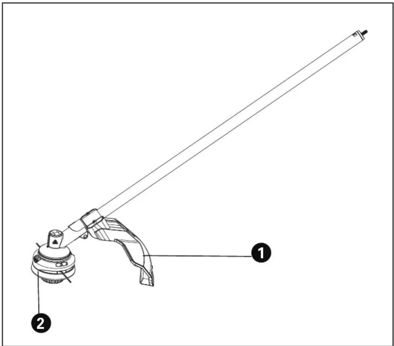
COMPONENT LIST
- DEBRIS GUARD
- TRIMMER HEAD
PRODUCT SAFETY GENERAL OUTDOOR POWER EQUIPMENT SAFETY WARNINGS
WARNING: Read all safety warnings, instructions, illustrations and specifications provided with this outdoor power equipment.
Failure to follow all instructions listed below may result in electric shock, fire and/or serious injury.
Save all warnings and instructions for future reference.
The term "outdoor power equipment" in the warnings refers to your corded outdoor power equipment or battery-operated (cordless) outdoor power equipment.
1. Work area safety
a) Keep work area clean and well lit. Cluttered or dark areas invite accidents.
b) Do not operate outdoor power equipments in explosive atmospheres, such as in the presence of flammable liquids, gases or dust. Outdoor power equipments create sparks which may ignite the dust or fumes.
c) Keep children and bystanders away while operating a outdoor power equipment. Distractions can cause you to lose control.
2. Electrical safety
a) Outdoor power equipment plugs must match the outlet. Never modify the plug in any way. Do not use any adapter plugs with earthed (grounded) outdoor power equipments. Unmodified plugs and matching outlets will reduce risk of electric shock.
b) Avoid body contact with earthed or grounded surfaces, such as pipes, radiators, ranges and refrigerators. There is an increased risk of electric shock if your body is earthed or grounded.
c) Do not operate the machine in rain or wet conditions. This may increase the risk of electric shock. If the machine becomes wet in the rain during operation, the machine and the battery should be dried before storing or charging. Remove the battery and reinsert it if the machine fails to turn on. Keep battery connection free of dirt and debris, and clean with a soft and dry brush or cloth.
d) Do not abuse the cord. Never use the cord for carrying, pulling or unplugging the outdoor power equipment. Keep cord away from heat, oil, sharp edges or moving parts. Damaged or entangled cords increase the risk of electric shock.
e) When operating a outdoor power equipment outdoors, use an extension cord suitable for outdoor use. Use of a cord suitable for outdoor use reduces the risk of electric shock.
f) If operating a outdoor power equipment in a damp location is unavoidable, use a residual
current device (RCD) protected supply. Use of an RCD reduces the risk of electric shock.
3. Personal safety
a) Stay alert, watch what you are doing and use common sense when operating a outdoor power equipment. Do not use a outdoor power equipment while you are tired or under the influence of drugs, alcohol or medication. A moment of inattention while operating outdoor power equipments may result in serious personal injury.
b) Use personal protective equipment. Always wear eye protection. Protective equipment such as dust mask, non-skid safety shoes, hard hat, or hearing protection used for appropriate conditions will reduce personal injuries.
c) Prevent unintentional starting. Ensure the switch is in the off-position before connecting to power source and/or battery pack, picking up or carrying the tool. Carrying outdoor power equipments with your finger on the switch or energizing outdoor power equipments that have the switch on invites accidents.
d) Remove any adjusting key or wrench before turning the outdoor power equipment on. A wrench or a key left attached to a rotating part of the outdoor power equipment may result in personal injury.
e) Do not overreach. Keep proper footing and balance at all times. This enables better control of the outdoor power equipment in unexpected situations.
f) Dress properly. Do not wear loose clothing or jewellery. Keep your hair, clothing and gloves away from moving parts. Loose clothes, jewellery or long hair can be caught in moving parts.
g) If devices are provided for the connection of dust extraction and collection facilities, ensure these are connected and properly used. Use of dust collection can reduce dust-related hazards.
h) Do not let familiarity gained from frequent use of tools allow you to become complacent and ignore tool safety principles. A careless action can cause severe injury within a fraction of a second.
4. Outdoor power equipment use and care
a) Do not force the outdoor power equipment. Use the correct outdoor power equipment for your application. The correct outdoor power equipment will do the job better and safer at the rate for which it was designed.
b) Do not use the outdoor power equipment if the switch does not turn it on and off. Any outdoor power equipment that cannot be controlled with the switch is dangerous and must be repaired.
c) Disconnect the plug from the power source and/or the battery pack from the outdoor power equipment before making any adjustments, changing accessories, or storing outdoor power equipments. Such preventive
safety measures reduce the risk of starting the outdoor power equipment accidentally.
d) Store idle outdoor power equipments out of the reach of children and do not allow persons unfamiliar with the outdoor power equipment or these instructions to operate the outdoor power equipment. Outdoor power equipments are dangerous in the hands of untrained users.
e) Maintain outdoor power equipments. Check for misalignment or binding of moving parts, breakage of parts and any other condition that may affect the outdoor power equipment's operation. If damaged, have the outdoor power equipment repaired before use. Many accidents are caused by poorly maintained outdoor power equipments.
f) Keep cutting tools sharp and clean. Properly maintained cutting tools with sharp cutting edges are less likely to bind and are easier to control.
g) Use the outdoor power equipment, accessories and tool bits etc. in accordance with these instructions, taking into account the working conditions and the work to be performed. Use of the outdoor power equipment for operations different from those intended could result in a hazardous situation.
h) Keep handles and grasping surfaces dry, clean and free from oil and grease. Slippery handles and grasping surfaces do not allow for safe handling and control of the tool in unexpected situations.
- Battery tool use and care
a) Recharge only with the charger specified by the manufacturer. A charger that is suitable for one type of battery pack may create a risk of fire when used with another battery pack.
b) Use outdoor power equipments only with specifically designated battery packs. Use of any other battery packs may create a risk of injury and fire.
c) When battery pack is not in use, keep it away from other metal objects, like paper clips, coins, keys, nails, screws or other small metal objects, that can make a connection from one terminal to another. Shorting the battery terminals together may cause burns or a fire.
d) Under abusive conditions, liquid may be ejected from the battery; avoid contact. If contact accidentally occurs, flush with water. If liquid contacts eyes, additionally seek medical help. Liquid ejected from the battery may cause irritation or burns.
e) Do not use a battery pack or tool that is damaged or modified. Damaged or modified batteries may exhibit unpredictable behaviour resulting in fire, explosion or risk of injury.
f) Do not expose a battery pack or tool to fire or excessive temperature. Exposure to fire or temperature above 130 °C may cause explosion.
g) Follow all charging instructions and do not charge the battery pack or tool outside the temperature range specified in the instructions. Charging improperly or at temperatures outside the specified range may
damage the battery and increase the risk of fire.
- Service
a) Have your outdoor power equipment serviced by a qualified repair person using only identical replacement parts. This will ensure that the safety of the outdoor power equipment is maintained.
b) Never service damaged battery packs. Service of battery packs should only be performed by the manufacturer or authorized service providers.
GRASS TRIMMER SAFETY WARNINGS
a) Do not use the machine in bad weather conditions, especially when there is a risk of lightning. This decreases the risk of being struck by lightning.
b) Thoroughly inspect the area for wildlife where the machine is to be used. Wildlife may be injured by the machine during operation.
c) Thoroughly inspect the area where the machine is to be used and remove all stones, sticks, wires, bones, and other foreign objects. Thrown objects can cause personal injury.
d) Before using the machine, always visually inspect to see that the cutter or blade and the cutter or blade assembly are not damaged. Damaged parts increase the risk of injury.
e) Follow instructions for changing accessories. Improperly tightened blade securing nuts or bolts may either damage the blade or result in it becoming detached.
f) Wear eye, ear, head and hand protection. Adequate protective equipment will reduce personal injury by flying debris or accidental contact with the cutting line or blade.
g) While operating the machine, always wear non-slip and protective footwear. Do not operate the machine when barefoot or wearing open sandals. This reduces the chance of injury to the feet from contact with the moving cutters or lines.
h) While operating the machine, always wear long trousers. Exposed skin increases the likelihood of injury from thrown objects.
i) Keep bystanders away while operating the machine. Thrown debris can result in serious personal injury.
j) Always use two hands when operating the machine. Holding the machine with both hands will avoid loss of control.
k) Hold the machine by the insulated gripping surfaces only, because the cutting line or blade may contact hidden wiring. Cutting line or blades contacting a "live" wire may make exposed metal parts of the machine "live" and could give the operator an electric shock.
I) Always keep proper footing and operate the machine only when standing on the ground. Slippery or unstable surfaces may cause a loss of balance or control of the machine.
m) Do not operate the machine on excessively
steep slopes. This reduces the risk of loss of control, slipping and falling which may result in personal injury.
n) When working on slopes, always be sure of your footing, always work across the face of slopes, never up or down and exercise extreme caution when changing direction. This reduces the risk of loss of control, slipping and falling which may result in personal injury.
o) Keep all parts of the body away from the cutter, line or blade when the machine is operating. Before you start the machine, make sure the cutter, line or blade is not contacting anything. A moment of inattention while operating the machine may result in injury to yourself or others.
p) Do not operate the machine above waist height. This helps prevent unintended cutter or blade contact and enables better control of the machine in unexpected situations.
q) When cutting brush or saplings that are under tension, be alert for spring back. When the tension in the wood fibres is released, the brush or sapling may strike the operator and/or throw the machine out of control.
r) Use extreme caution when cutting brush and saplings. The slender material may catch the blade and be whipped toward you or pull you off balance.
s) Maintain control of the machine and do not touch cutters, lines or blades and other hazardous moving parts while they are still in motion. This reduces the risk of injury from moving parts.
t) Carry the machine with the machine switched off and away from your body. Proper handling of the machine will reduce the likelihood of accidental contact with a moving cutter, line or blade.
u) Only use replacement cutters, lines, cutting heads and blades specified by the manufacturer. Incorrect replacement parts may increase the risk of breakage and injury.
v) When clearing jammed material or servicing the machine, make sure the switch is off and the battery pack is removed. Unexpected starting of the machine while clearing jammed material or servicing may result in serious personal injury.
SAFETY WARNINGS FOR BATTERY PACK
a) Do not dismantle, open or shred cells or battery pack.
b) Do not short-circuit a battery pack. Do not store battery packs haphazardly in a box or drawer where they may short-circuit each other or be short-circuited by conductive materials. When battery pack is not in use, keep it away from other metal objects, like paper clips, coins, keys, nails, screws or other small metal objects, that can make a connection from one terminal to another. Shorting the battery terminals together may cause burns or a fire.
c) Do not expose battery pack to heat or fire.
Avoid storage in direct sunlight.
d) Do not subject battery pack to mechanical shock.
e) In the event of battery leaking, do not allow the liquid to come into contact with the skin or eyes. If contact has been made, wash the affected area with copious amounts of water and seek medical advice.
f) Keep battery pack clean and dry.
g) Wipe the battery pack terminals with a clean dry cloth if they become dirty.
h) Battery pack needs to be charged before use. Always refer to this instruction and use the correct charging procedure.
i) Do not maintain battery pack on charge when not in use.
j) After extended periods of storage, it may be necessary to charge and discharge the battery pack several times to obtain maximum performance.
k) Recharge only with the charger specified by Kress. Do not use any charger other than that specifically provided for use with the equipment.
I) Do not use any battery pack which is not designed for use with the equipment.
m) Keep battery pack out of the reach of children.
n) Retain the original product literature for future reference.
o) Remove the battery from the equipment when not in use.
p) Dispose of properly.
q) Do not mix cells of different manufacture, capacity, size or type within a device.
r) Keep the battery away from microwaves and high pressure.
S) Warning! Do not use non-rechargeable batteries.
SAVE THESE INSTRUCTIONS
SYMBOLS
 | To reduce the risk of injury, user must read instruction manual |
 | Wear eye protection |
 | Wear ear protection |
 | WARNING – The distance between the machine and bystanders shall be at least 15 m (50 ft) |
 | WARNING – Beware of thrown objects |
 | Do not use metal blades |
 | WARNING – Disconnect battery before maintenance |
 | Wear hand protection |
 | Li-Ion battery This product has been marked with a symbol relating to ‘separate collection’ for all battery packs and battery pack. It will then be recycled or dismantled in order to reduce the impact on the environment. Battery packs can be hazardous for the environment and for human health since they contain hazardous substances. |
| Li-Ion | |
 | |
 | Do not burn |
 | Batteries may enter water cycle if disposed improperly, which can be hazardous for ecosystem. Do not dispose of waste batteries as unsorted municipal waste. |
 | Do not expose to moisture. |
 | Trimming |
 | Waste electrical products must not be disposed of with household waste. Please recycle where facilities exist. Check with your local authorities or retailer for recycling advice. |
NOTE: Before using the tool, read the instruction book carefully.

BEFORE OPERATION:
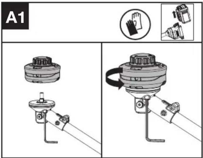
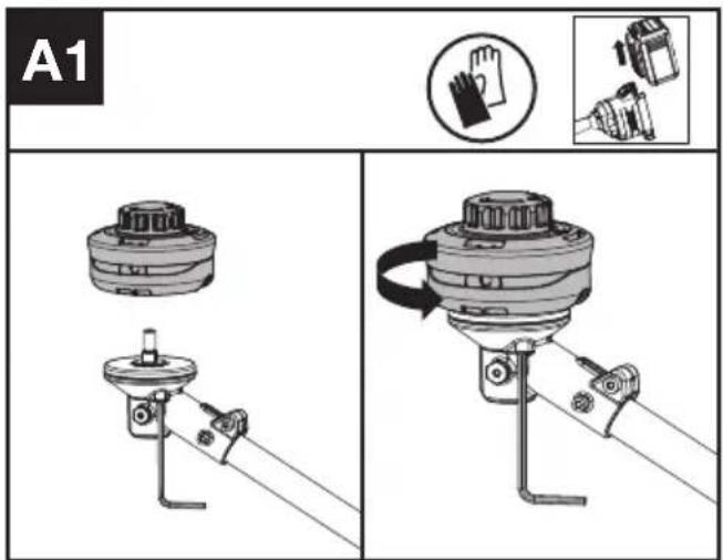
Assembling the cutting head (See Fig. A1)
- Fit the cutting head. Insert the torx key into the hole and rotate the trimmer head counterclockwise until it stops in a locked position.
Assembling the debris guard (See Fig. A2)
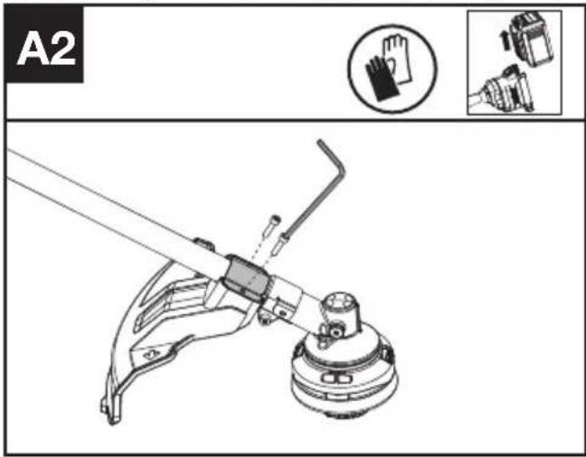
- Install the correct Debris Guard for the trimmer head.
- Secure the guard in place using the screw and torx key.
MAINTENANCE

WARNING! Always remove battery before conducting any maintenance on the
trimmer.
Replacing the trimmer head (See Fig. B)

WARNING! Use of wire or metal-reinforced line is not authorized and could be
extremely dangerous. Use only the cutting line recommended in this manual, in combination with the recommended debris guard.
WARNING! A damaged or loose cutting attachment head may vibrate, crack, break or come off the trimmer, which may result in serious or fatal injury or property damage. Make sure the trimmer head are properly and securely tightened and in good condition before starting work.
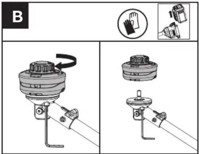
- Insert the torx key into the hole and rotate the trimmer head until it stops in a locked position.
- Then, rotate clockwise to remove it, and counterclockwise to assemble it. (See Fig. A1)
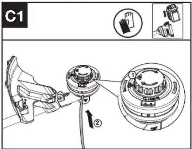
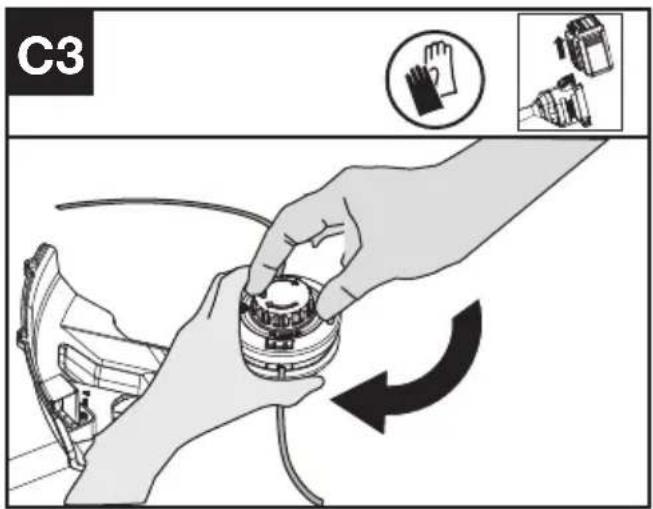
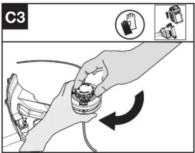
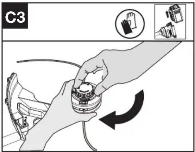
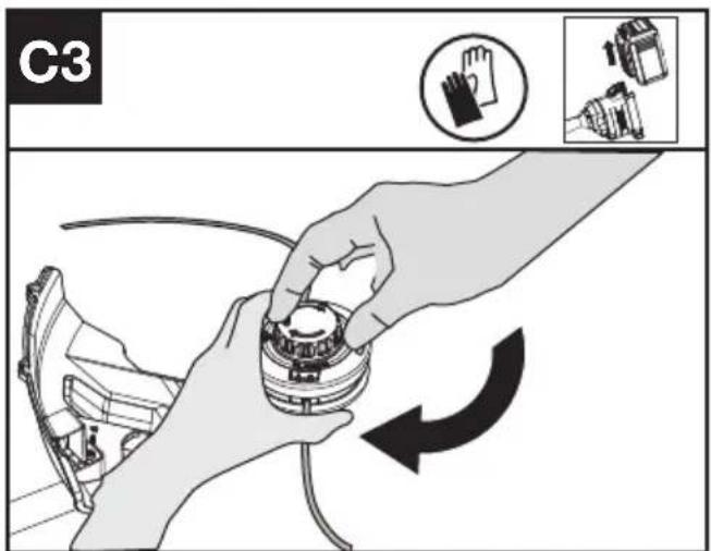
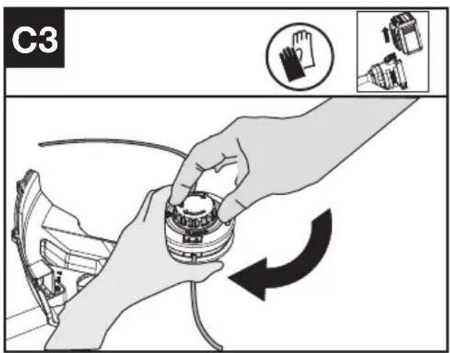
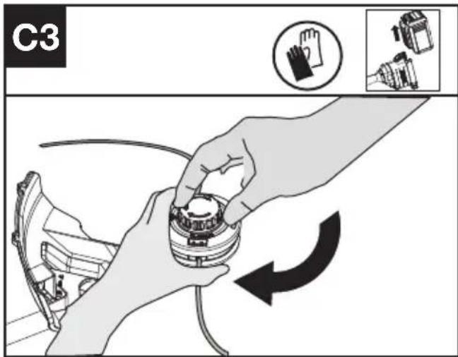
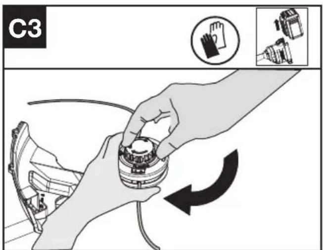
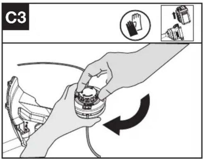
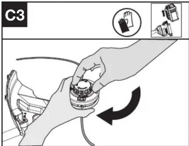
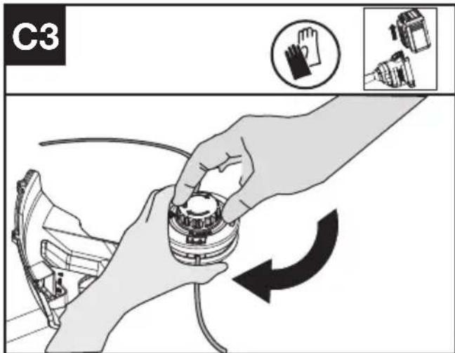
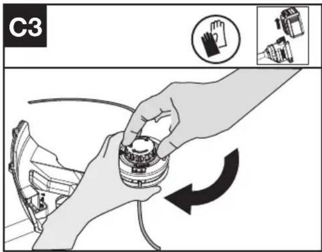
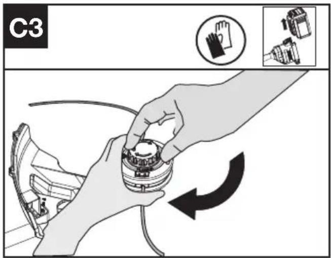
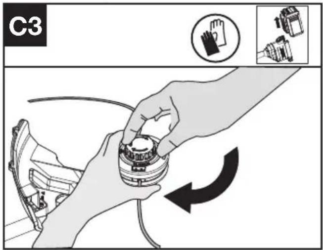
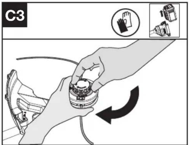
Winding the line (See Fig. C1, C2, C3)
- Rotate the spool cap until the two triangle icons are aligned. (See Fig. C1)
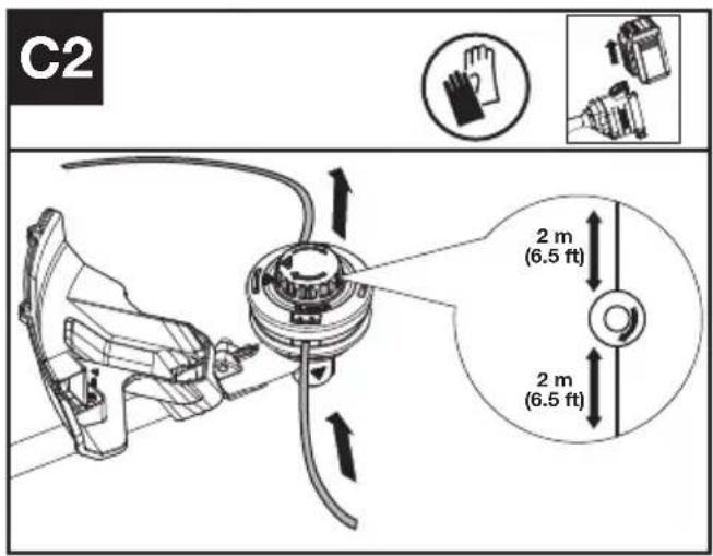
- Insert the replacement line through the eyelet (Line In) and feed it out through the other eyelet. Ensure both ends of the line are even on each side of the trimmer head (recommended 6.5 ft (2 m) and cut the line. (See Fig. C2)
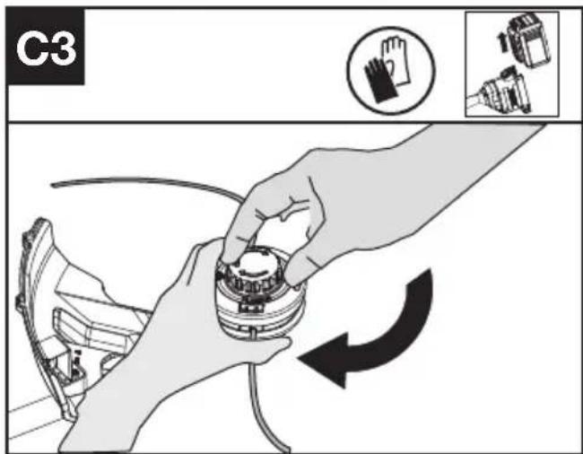
- Turn the dial clockwise to wind the line around the spool until about 6''(16 cm) remains on either side. (See Fig. C3)
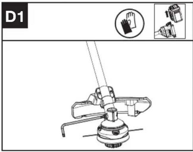
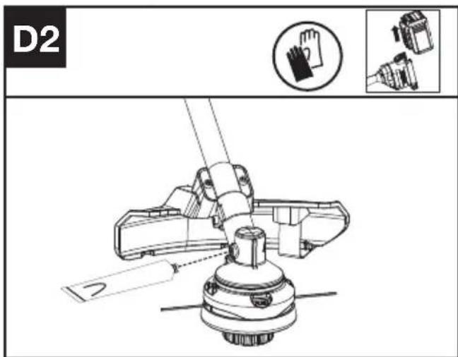
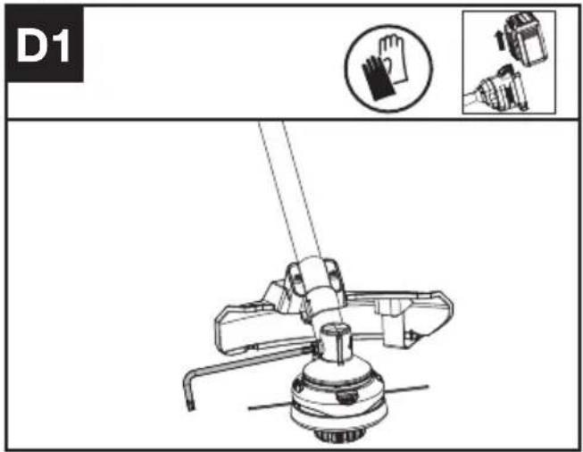
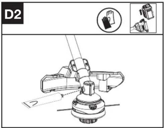
Lubricating the gearbox (See Fig. D1, D2)
- Remove the screw on the gearbox.
- If there is no bevel gear grease on the end of the screw, squeeze 5 g of the gear grease (SHELL Gadus S2 V220 1) into the gear housing.
- Refit and tighten the screw firmly.
- Install the battery and run the trimmer for 1 minute to ensure the gear is evenly lubricated.
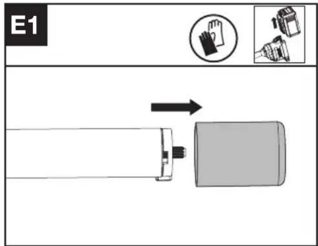
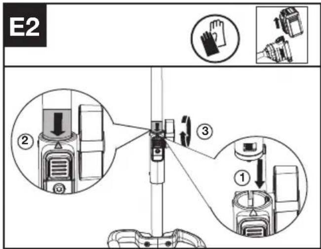
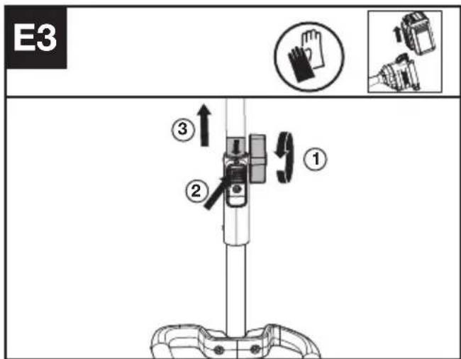
Assembling and disassembling the Power head attachment. (See Fig. E1, E2, E3)
- Remove the protective cap from the end of the attachment shaft.
- To assemble, align the triangle icon on the button with the arrow label on the attachment shaft.
- Push the shafts together until you hear a "click". The edge of the arrow label should be close to the shaft connection housing.(Note: If the trimmer shaft cannot be fully installed into the power hear, rotate the trimmer head a little until it is possible to insert the shaft fully.)
- Finish the assembly by tightening the knob clockwise.
- To disassemble, loosen the knob, turn counter clockwise, then press the release button and pull the shafts apart. Replace the protective cap on the attachment shaft to ensure that dust and debris do not get into the shaft.
CLEANING
- Switch off the trimmer and remove the battery.
- Do not use aggressive detergents or solvents. Clean the machine after use with a damp cloth dipped in mild detergent.
- Keep battery connection free of dirt and debris, and clean with a soft and dry brush or cloth.
- Do not spray water onto the motor and electrical components.
- Do not use pressure washer to clean your
machine.
STORAGE
- Remove the battery pack from the trimmer before storage.
- If the machine becomes wet in the rain during operation, the machine and the battery should be dried before storing or charging. Remove the battery and reinsert it if the machine fails to turn on.
- Store the trimmer and the battery in a dry and secure place that is inaccessible to children and other unauthorized people.
Remove the cutting attachment if no use for a long time.
- Store the battery only within a temperature range between 41^ F ( 5^ C) and 77^ F ( 25^ C). As an example, do not leave the battery in the car in summer time.
TROUBLESHOOTING
The following table gives problems and actions that you can perform if your machine does not operate correctly.

WARNING: Switch the machine off and remove the battery prior to any troubleshooting.
TRIMMER
| Problems Possible | Causes Corrective Action | |
| Battery indicator LED flashing | Low battery voltage. Charge the battery. | |
| Red error LED flashing Overload. The cutting attachment is jammed. | ||
TECHNICAL DATA
Type Designation: KAC105
| KAC105 | |
| Cutting speed | 4500 / 5900 rpm |
| Cutting diameter | 42cm |
| Line diameter | 2.4 / 2.7 mm nylon line |
| Degree of protection | IPX4 |
| Machine weight (Bare tool) | 1.5 kg |
COMBINATIONS OF CUTTING ATTACHMENTS, DEFLECTORS, AND CARRYING SYSTEMS
| Cutting attachment Debris guard Barrier bar Carrying system | |||
| - 4" Trimmer head- 5" Trimmer head(Optional, not included) | - High-visibility deflector- Universal deflector with skirt | - Optional | - Shoulder strap (KAC130)- Backpack battery Harness (KAC900) |
| - Knife blade (KAC170) | - Universal deflector without skirt | - Required | |
NOISE INFORMATION
| A weighted sound pressure L | _pA =85 dB(A) |
| K_pA | 3 dB(A) |
| A weighted sound power L | _wA =94 dB(A) |
| K_wA | 1.17 dB(A) |
| Wear ear protection. |
VIBRATION INFORMATION
| Typical weighted vibration a | _h=2.36 m/s^2 |
| Uncertainty K =1.5 m/s^2 |

WARNING: The vibration emission value during actual use of the power tool can differ from the declared value depending on the ways in which the tool is used dependant on the following examples and other
variations on how the tool is used:
How the tool is used and the materials being cut or drilled.
The tool being in good condition and well maintained
The use the correct accessory for the tool and ensuring it is sharp and in good condition.
The tightness of the grip on the handles and if any anti vibration accessories are used.
And the tool is being used as intended by its design and these instructions.
This tool may cause hand-arm vibration syndrome if its use is not adequately managed.

WARNING: To be accurate, an estimation of exposure level in the actual conditions of use should also take account of all parts of the operating cycle such as the times when the tool is switched off and when it is
running idle but not actually doing the job. This may significantly reduce the exposure level over the total working period.
Helping to minimise your vibration exposure risk.
ALWAYS use sharp chisels, drills and blades
Maintain this tool in accordance with these instructions and keep well lubricated (where appropriate)
If the tool is to be used regularly then invest in anti vibration accessories.
Plan your work schedule to spread any high vibration tool use across a number of days.
ENVIRONMENTAL PROTECTION

Waste electrical products must not be disposed of with household waste. Please
recycle where facilities exist. Check with your local authorities or retailer for recycling advice.
DECLARATION OF CONFORMITY
We,
Positec Germany GmbH
Postfach 680194, 50704 Cologne, Germany
On behalf of Positec declare that the product
Description Cordless Grass Trimmer
Type KAC105 (1-designation of machinery, representative of Cordless Grass Trimmer)
Function cutting small weeds, grass and similar soft vegetation
Complies with the following Directives:
2006/42/EC, 2014/30/EU, 2011/65/EU & (EU)
2015/863, 2000/14/EC amended by 2005/88/EC
2000/14/EC amended by 2005/88/EC:
- Conformity Assessment Procedure as per Annex VI
- Measured Sound Power Level 94 dB (A)
- Declared Guaranteed Sound Power Level 96 dB (A)
The notified body involved
Name: TÜV Rheinland LGA Products GmbH (Notified body 0197)
Address: Tillystraße 2-90431 Nürnberg
Standards conform to
EN 62841-1, FprEN IEC
62841-4-4:2020+FprAA:2021-02, EN 62233, EN
ISO 3744, EN IEC 55014-1, EN IEC 55014-2, EN IEC 63000
The person authorized to compile the technical file,
Name Marcel Filz
Address Positec Germany GmbH
Postfach 680194, 50704 Cologne, Germany


2024/01/05
Allen Ding
Deputy Chief Engineer, Testing & Certification
Positec Technology (China) Co., Ltd
18, Dongwang Road, Suzhou Industrial
Park, Jiangsu 215123, P. R. China
DECLARATION OF CONFORMITY
We,
Positec (UK & Ireland) Ltd
PO Box 6242, Newbury, RG14 9LT, UK
On behalf of Positec declare that the product
Description Cordless Grass Trimmer
Type KAC105 (1-designation of machinery,
representative of Cordless Grass Trimmer)
Function cutting small weeds, grass and similar soft vegetation
Complies with the following Directives:
Supply of Machinery (Safety) Regulations 2008
Electromagnetic Compatibility Regulations 2016
The Restriction of the Use of Certain Hazardous
Substances in Electrical and Electronic
Equipment Regulations
Noise Emission in the Environment by Equipment for Use Outdoors Regulations
- Conformity Assessment Procedure as per
SCHEDULE 9
- Measured Sound Power Level 94 dB (A)
- Declared Guaranteed Sound Power Level 96 dB (A)
The notified body involved
Name: TÜV Rheinland LGA Products GmbH
(Notified body 0197)
Address: Tillystraße 2-90431 Nürnberg
Standards conform to
BS EN 62841-1, FprBS EN IEC
62841-4-4:2020+FprAA:2021-02, BS EN 62233,
BS EN ISO 3744, BS EN IEC 55014-1, BS EN IEC
55014-2, BS EN IEC 63000
The person authorized to compile the technical file,
Name Jim Kirkwood
Address Positec (UK & Ireland) Ltd,
PO Box 6242, Newbury, RG14 9LT, UK


2024/01/05
Allen Ding
Deputy Chief Engineer, Testing & Certification
Positec Technology (China) Co., Ltd
18, Dongwang Road, Suzhou Industrial
Park, Jiangsu 215123, P. R. China
INHALTSVERZEICHNIS
Einführung....14
Komponenten....15
KOMPONENTEN
- SCHNEIDSCHUTZ
- FADENKOPF
- Fit the cutting head. Insert the torx key into the hole and rotate the trimmer head counterclockwise until it stops in a locked position.
DECLARATION OF CONFORMITY
We,
Positec Germany GmbH
Postfach 680194, 50704 Cologne, Germany
Complies with the following Directives:
2006/42/EC, 2014/30/EU, 2011/65/EU & (EU)
18, Dongwang Road, Suzhou Industrial
Park, Jiangsu 215123, P. R. China
SOMMAIRE
Introduction....26
LISTE DES COMPOSANTS
- PROTECTION ANTI-DÉBRIS
- TÊTE DE COUPE
NOTICE ORIGINALE AVERTISSEMENTS DE SÉCURITÉ SÉCURITÉ DU PRODUIT AVERTISSEMENTS GÉNÉRAUX DE SÉCURITÉ POUR L'OUTIL

INFORMATIONS RELATIVES AU BRUIT
INFORMATIONS RELATIVES AUX VIBRATIONS
18, Dongwang Road, Suzhou Industrial
Park, Jiangsu 215123, P. R. China
INDICE
Introduzione....38
ELENCO COMPONENTI
18, Dongwang Road, Suzhou Industrial
Park, Jiangsu 215123, P. R. China
ÍNDICE
Introducción....50
Lista de componentes....51
18, Dongwang Road, Suzhou Industrial
Park, Jiangsu 215123, P. R. China
ÍNDICE
Introdução....62
2015/863, 2000/14/EC amended by 2005/88/EC
18, Dongwang Road, Suzhou Industrial
Park, Jiangsu 215123, P. R. China
INHOUDSOPGAVE
ONDERDELENLIJST
- BESCHERMKAP
- FIJNAFSTEMMINGSKOP
OORSPRONKELIJKE GEBRUI- KSAANWIJZING VEILIGHEIDSWAARSCHUWINGEN ALGEMENE VEILIGHEIDSWAARSCHUWINGEN VOOR VERMOGENSMACHINE

WAARSCHUWING: Lees alle veiligheidswaarschuwingen,

Type Designation: KAC105
18, Dongwang Road, Suzhou Industrial
Park, Jiangsu 215123, P. R. China
TARTALOMJEGYZÉK
Bevezető....86

18, Dongwang Road, Suzhou Industrial
Park, Jiangsu 215123, P. R. China
CUPRINS
Introducere....98
LISTA DE COMPONENTE
- PROTECTIEI ÎMPOTRIVA RESTURILOR
- CAP DE REGLARE FINĂ
INSTRUCTIUNI ORIGINALE SECURITATEA PRODUSULUI AVERTISMENTE GENERALE DE SIGURANTĂ PENTRU UNELTE ELECTRICE
18, Dongwang Road, Suzhou Industrial
Park, Jiangsu 215123, P. R. China
SPIS TREŚCI
Wprowadzenie....110
LISTA KOMPONENTÓW
- OSŁONY PRZED ŚMIECIAMI
- GŁOWICA DOSTRAJAJĄCA
INSTRUKCJA ORYGINALNA BEZPIECZEŃSTWO PRODUKTU OGÓLNE OSTRZEŻENIA DOTYCZĄCE BEZPIECZEŃSTWA PODCZAS PRACY Z ELEKTRONARZĘDZIAMI
18, Dongwang Road, Suzhou Industrial
Park, Jiangsu 215123, P. R. China
OBSAH
Úvod....122
SEZNAM KOMPONENTÜ
- OCHRANNÉHO KRYTU PROTI NEČISTOTÁM
- JEMNĚ VYLADĚNÁ HLAVA
PŮVODNÍ NÁVOD K POUŽÍVÁNÍ BEZPEČNOST VÝROBKU OBECNÁ BEZPEČNOSTNÍ UPOZORNĚNÍ PRO ELEKTRICKÉ NÁSTROJE

TYTO POKYNY USCHOVEJTE
SYMBOLY
INFORMACE TÝKAJÍCÍ SE HLUČNOSTI
18, Dongwang Road, Suzhou Industrial
Park, Jiangsu 215123, P. R. China
OBSAH
Úvod....134
ZOZNAM SÚČASTÍ
- OCHRANNÉHO KRYTU PROTI ÚLOMKOM
- JEMNE VYLADENÁ HLAVA
PÔVODNÝ NÁVOD NA POUŽITIE BEZPEČNOST VÝROBKU VŠEOBECNÉ BEZPEČNOSTNÉ UPOZORNENIA

TIETO POKYNY USCHOVAJTE
SYMBOLY
18, Dongwang Road, Suzhou Industrial
Park, Jiangsu 215123, P. R. China
KAZALO VSEBINE
Uvod....146
Sestavni deli....147
Varnost izdelka....148
Sestavljanje in delovanje....151
Vzdrževanje....152
Čiščenje....154
Shranjevanje....154
SESTAVNI DELI
- ŠČITNIKA ZA OBREZKE
- GLAVA ZA FINO NASTAVITEV
IZVIRNA NAVODILA VARNOST IZDELKA SPLOŠNA VARNOSTNA OPOZORILA

- Skozi očesce vstavite nadomestno nitko (nitka vstavljena) in jo povlecite ven skozi drugo očesce. Prepričajte se, da sta oba konca nitke enakomerno velika na vsakem koncu glave obrezovalnika (priporočeno 2 m (6.5 čevljev)) in odrežite nitko. (Glej sliko C2)
- Zavrtite gumb v smeri urinega kazalca, da nitko ovijete okoli motka, dokler je na vsaki strani ne ostane okrog 16 cm (6"). (Glej sliko C3)
POPIS KOMPONENTI
- ŠTITNIK OD KRHOTINA
- GLAVA TRIMERA
ORIGINALNE UPUTE ZA RAD SIGURNOST PROIZVODA UOBIČAJENA SIGURNOSNA UPOZORENJA ZA ELEKTRIČNE ALATE

UPOZORENJE Pročitajte sva sigurnosna upozorenja, upute, ilustracije i specifikacije
- Umetnite zamjensku nit kroz ušicu (nit unutra) i provucite ju kroz vanjsku ušicu. Uvjerite se da su oba kraja niti jednaka s obje strane glave trimera (preporučeno 2 m (6.5 ft)) i odrežite nit. (vidi sl. C2)
- Okrenite kotačić u smjeru kazaljke na satu kako biste namotali nit oko kalema dok ne ostane oko 16 cm (6") s obje strane. (vidi sl. C3)
Podmazivanje reduktora (vidi sl. D1, D2)
- Uklonite vijak s reduktora.
-
Ako na kraju vijka nema masti za konusne zupčanike, istisnite 5 g masti (SHELL Gadus S2 V220 1) za zupčanike u kućište zupčanika.
-
Vratite vijak i zategnite ga.
- Umetnite bateriju i upalite trimer na 1 minutu kako biste se uvjerili da je zupčanik ravnomjerno podmazan.
Sastavljanje i rastavljanje nastavka pogonske glave. (vidi sl. E1, E2, E3)
18, Dongwang Road, Suzhou Industrial
Park, Jiangsu 215123, P. R. China
INDHOLDSFORTEGNELSE
Introduktion....168
Lista de componentes....169
18, Dongwang Road, Suzhou Industrial
Park, Jiangsu 215123, P. R. China
SISÄLLYSLUETTELO
Johdanto....179
Komponenttiluettelo....180
KOMPONENTTILUETTELO
- ROSKASUOJA
- TRIMMERIPÄÄ
ALKUPERÄISET OHJEET TURVALLISUUSOHJEET TUOTETURVALLISUUS YLEISET SÄHKÖTYÖKALUJEN TURVALLISUUTEEN LIITTYVÄT VAROITUKSET

18, Dongwang Road, Suzhou Industrial
Park, Jiangsu 215123, P. R. China
INNHOLDFORTEGNELSE
Introduksjon....190
Apparatelementer....191
Produktsikkerhet....192
APPARATELEMENTER
- BESKYTTELSESSKJERMEN
- FINJUSTERINGSHODE
ORIGINAL DRIFTSINSTRUKS PRODUKTSIKKERHET GENERELLE ADVARSLER FOR ELEKTROVERKT∅Y

ADVARSEL Les alle
To reduce the risk of injury, user must read instruction manual

Bruk vernebriller
18, Dongwang Road, Suzhou Industrial
Park, Jiangsu 215123, P. R. China
INNEHÅLLSFÖRTECKNING
Introduktion....201
Komponenter....202
Produktsäkerhet 203
KOMPONENTER
- STÄNKSKYDD
- TRIMMERHUVUD
BRUKSANVISNING I ORIGINAL SÄKERHETSFÖRESKRIFTER SÄKERHETSVARNINGAR GENERELLA SÄKERHETS-VARNINGAR FÖR ELVERK-TYG

18, Dongwang Road, Suzhou Industrial
Park, Jiangsu 215123, P. R. China