KC111.9 - Grass trimmer KRESS - Free user manual and instructions
Find the device manual for free KC111.9 KRESS in PDF.

| Product type | Cordless grass trimmer |
| Brand | Kress |
| Model | KC111.9 |
| Rated voltage | 54 V (max 60 V) |
| Cutting speed | 4500 / 5000 / 5500 rpm |
| Cutting diameter | 42 cm |
| Line diameter | 2.4 mm or 2.7 mm (nylon) |
| Weight (bare tool) | 3.7 kg |
| Protection rating | IPX4 |
| Battery type | Lithium-Ion (recommended: KAC804 4.0 Ah, KAC810 11.0 Ah) |
| Recommended charger | KAC840 (30 A) or KAC810 |
| Sound pressure level | 77.3 dB(A) |
| Sound power level | 90.84 dB(A) |
| Vibrations | < 2.5 m/s² (uncertainty K=1.5 m/s²) |
| Included accessories | 4'' cutting head, debris guard, harness, handlebar |
| Main features | Linear advance system (tap-and-go), speed selection (3 levels), LED indicator, operator presence switch |
| Maintenance and cleaning | Clean with a damp cloth; do not use pressurized water; dry before storage |
| Safety | Debris guard, automatic shutdown, safety lock, two-hand operation, recommended PPE (eyes, ears, shoes, gloves) |
| Operating temperature | Discharge: -20°C to 45°C; charge: -5°C to 45°C |
| Spare parts available | 4''/5'' cutting heads, knife blade (KAC171), nylon line, batteries, chargers |
Frequently Asked Questions - KC111.9 KRESS
User questions about KC111.9 KRESS
0 question about this device. Answer the ones you know or ask your own.
Ask a new question about this device
Download the instructions for your Grass trimmer in PDF format for free! Find your manual KC111.9 - KRESS and take your electronic device back in hand. On this page are published all the documents necessary for the use of your device. KC111.9 by KRESS.
USER MANUAL KC111.9 KRESS
natural_image
Mechanical assembly with articulated joints and connecting rods (no visible text or symbols)| Commercial 60V Front motor bike handle line trimmer | EN | P03 |
| Kommerzieller 60-V-Fadentrimmer mit Frontmotor und Motorrad-Griff | D | P19 |
| Débroussailleuse à batterie de 60 V avec poignée en forme de guidon de vélo et moteur à l'avant pour un usage commercial | F | P36 |
| Tagliabordi commerciale 60V con motore anteriore e con manico per bicicletta | I | P53 |
| Recortadora con manillar doble Comercial de 60V | ES | P69 |
| Aparador de bermas comercial de 60 V com motor frontal e guiador de bicicleta | PT | P85 |
| Commerciële 60V grastrimmer met voormotor en fietsstuur | NL | P101 |
| 60V-os első motoros szegélyvágó kerékpárfogantyúval | HU | P117 |
| Motocoasă comercială cu ghidon, motor frontal, 60V | RO | P134 |
| Przedniosilnikowa komercyjna podkaszarka żyłkowa z uchwytem oburęcznym 60 V | PL | P151 |
| Komerční 60V zastřihovač okrajů trávníku s rukojetí | CZ | P168 |
| Komerčný 60 V strunový vyžínač s rovnou rukoväťou | SK | P184 |
| Komercialni prirezovalnik s sprednjim motorjem in kolesarskim ročajem 60 V | SL | P201 |
| Komercijalni 60V motorni trimer za travu s bicikl ručkama | HR | P217 |
| Kommerciel 60 V linjetrimmer med frontmotor og håndtag | DK | P233 |
| Kaupallinen 60 V etumoottorillinen pyöränkahva siimatrimmeri | FIN | P248 |
| Kommersiell 60V kantklipper med frontmotor og håndtak | NOR | P263 |
| Kommersiell 60V främre handtagslinjetrimmer för motorcykel | SV | P278 |
KC111 KC111.X
TABLE OF CONTENTS
Introduction....3
Component List....4
Product Safety....6
Assembly & Operation....10
Transportation....13
Maintenance....13
Cleaning....14
Storage....14
Troubleshooting....15
Technical Data....15
Environmental Protection....17
Declaration of Conformity....17
INTRODUCTION
Dear Customer,
Thank you for buying this Kress Commercial product. We are dedicated to developing high quality products to meet your commercial landscaping requirements.
The Kress brand is synonymous with premium quality service. Over the years of your product's life, if you have any questions or concerns about your product, please contact your dealer or our Customer Service Team for assistance.
We are confident you will enjoy working with your Kress product for years to come.
INTENDED USE
This machine is intended for cutting grass and high weeds that cannot be reached with a lawn mower. This machine is also used on areas with slopes not conducive to mowing.
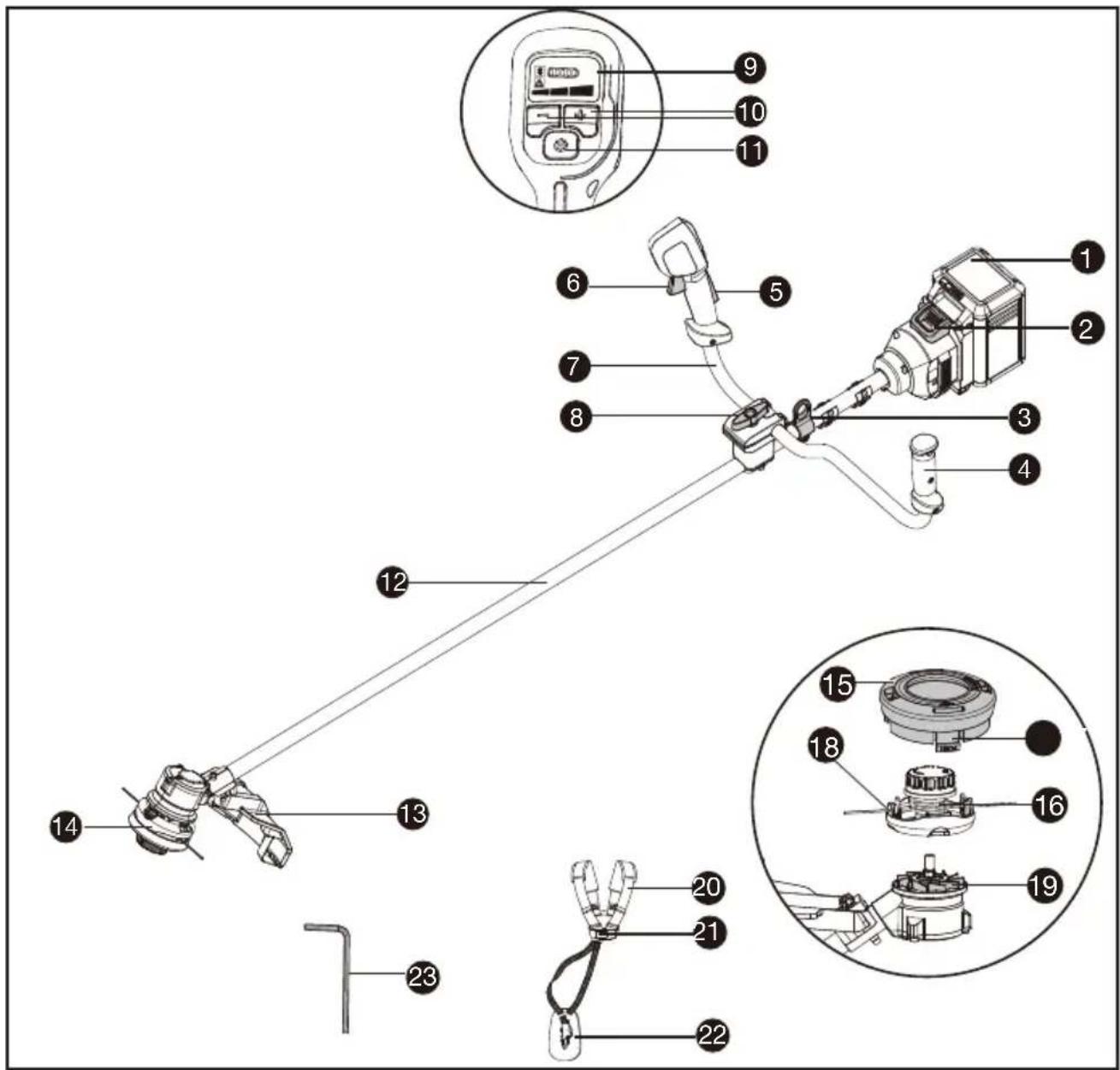
COMPONENT LIST
- BATTERY PACK *
- BATTERY REALEASE BUTTON
- HARNESS ATTACHMENT POINT
- HAND GRIP
- OPERATOR PRESENCE SWITCH
- THROTTLE TRIGGER
- BIKE HANDLE
- CLAMP BOLT
- DISPLAY SCREEN
- SPEED CONTROL BUTTON
- ON/OFF BUTTON
- SHAFT
- GUARD ASSEMBLY
| 14. TRIMMER HEAD |
| 15. SPOOL CAP |
| 16. SPOOL |
| 17. CAP RELEASE LATCH |
| 18. EYELET |
| 19. FAN |
| 20. SHOULDER STRAP |
| 21. HARNESS BUCKLE |
| 22. HIP-PAD |
| 23. TORX KEY |
* Not all the accessories illustrated or described are included in standard delivery.
ORIGINAL INSTRUCTIONS PRODUCT SAFETY GENERAL POWER TOOL SAFETY WARNINGS

WARNING Read all safety warnings, instructions, illustrations and specifications
provided with this power tool. Failure to follow all instructions listed below may result in electric shock, fire and/or serious injury.
Save all warnings and instructions for future reference.
The term "power tool" in the warnings refers to your mains-operated (corded) power tool or battery-operated (cordless) power tool.
1) Work area safety
a) Keep work area clean and well lit. Cluttered or dark areas invite accidents.
b) Do not operate power tools in explosive atmospheres, such as in the presence of flammable liquids, gases or dust. Power tools create sparks which may ignite the dust or fumes.
c) Keep children and bystanders away while operating a power tool. Distractions can cause you to lose control.
2) Electrical safety
a) Power tool plugs must match the outlet. Never modify the plug in any way. Do not use any adapter plugs with earthed (grounded) power tools. Unmodified plugs and matching outlets will reduce risk of electric shock.
b) Avoid body contact with earthed or grounded surfaces, such as pipes, radiators, ranges and refrigerators. There is an increased risk of electric shock if your body is earthed or grounded.
c) Do not operate the machine in rain or wet conditions. This may increase the risk of electric shock. If the machine becomes wet in the rain during operation, the machine and the battery should be dried before storing or charging. Remove the battery and reinsert it if the machine fails to turn on. Keep battery connection free of dirt and debris, and clean with a soft and dry brush or cloth.
d) Do not abuse the cord. Never use the cord for carrying, pulling or unplugging the power tool. Keep cord away from heat, oil, sharp edges or moving parts. Damaged or entangled cords increase the risk of electric shock.
e) When operating a power tool outdoors, use an extension cord suitable for outdoor use. Use of a cord suitable for outdoor use reduces the risk of electric shock.
f) If operating a power tool in a damp location is unavoidable, use a residual current device (RCD) protected supply. Use of an RCD reduces the risk of electric shock.
3) Personal safety
a) Stay alert, watch what you are doing and use common sense when operating a power tool. Do not use a power tool while you are tired or under the influence of drugs, alcohol or medication. A moment of inattention while operating power tools may result in serious personal injury.
b) Use personal protective equipment. Always wear eye protection. Protective equipment such as dust mask, non-skid safety shoes, hard hat, or hearing protection used for appropriate conditions will reduce personal injuries.
c) Prevent unintentional starting. Ensure the switch is in the off-position before connecting to power source and/or battery pack, picking up or carrying the tool. Carrying power tools with your finger on the switch or energising power tools that have the switch on invites accidents.
d) Remove any adjusting key or wrench before turning the power tool on. A wrench or a key left attached to a rotating part of the power tool may result in personal injury.
e) Do not overreach. Keep proper footing and balance at all times. This enables better control of the power tool in unexpected situations.
f) Dress properly. Do not wear loose clothing or jewellery. Keep your hair and clothing away from moving parts. Loose clothes, jewellery or long hair can be caught in moving parts.
g) If devices are provided for the connection of dust extraction and collection facilities, ensure these are connected and properly used. Use of dust collection can reduce dust-related hazards.
h) Do not let familiarity gained from frequent use of tools allow you to become complacent and ignore tool safety principles. A careless action can cause severe injury within a fraction of a second.
4) Power tool use and care
a) Do not force the power tool. Use the correct power tool for your application. The correct power tool will do the job better and safer at the rate for which it was designed.
b) Do not use the power tool if the switch does not turn it on and off. Any power tool that cannot be controlled with the switch is dangerous and must be repaired.
c) Disconnect the plug from the power source and/or remove the battery pack, if detachable, from the power tool before making any adjustments, changing accessories, or storing power tools. Such preventive safety measures reduce the risk of starting the power tool accidentally.
d) Store idle power tools out of the reach of children and do not allow persons unfamiliar with the power tool or these instructions to operate the power tool. Power tools are dangerous in the hands of untrained users.
e) Maintain power tools and accessories. Check for misalignment or binding of moving parts, breakage of parts and any other condition
that may affect the power tool's operation. If damaged, have the power tool repaired before use. Many accidents are caused by poorly maintained power tools.
f) Keep cutting tools sharp and clean. Properly maintained cutting tools with sharp cutting edges are less likely to bind and are easier to control.
g) Use the power tool, accessories and tool bits etc. in accordance with these instructions, taking into account the working conditions and the work to be performed. Use of the power tool for operations different from those intended could result in a hazardous situation.
h) Keep handles and grasping surfaces dry, clean and free from oil and grease. Slippery handles and grasping surfaces do not allow for safe handling and control of the tool in unexpected situations.
5) Battery tool use and care
a) Recharge only with the charger specified by the manufacturer. A charger that is suitable for one type of battery pack may create a risk of fire when used with another battery pack.
b) Use power tools only with specifically designated battery packs. Use of any other battery packs may create a risk of injury and fire.
c) When battery pack is not in use, keep it away from other metal objects, like paper clips, coins, keys, nails, screws or other small metal objects, that can make a connection from one terminal to another. Shorting the battery terminals together may cause burns or a fire.
d) Under abusive conditions, liquid may be ejected from the battery; avoid contact. If contact accidentally occurs, flush with water. If liquid contacts eyes, additionally seek medical help. Liquid ejected from the battery may cause irritation or burns.
e) Do not use a battery pack or tool that is damaged or modified. Damaged or modified batteries may exhibit unpredictable behaviour resulting in fire, explosion or risk of injury.
f) Do not expose a battery pack or tool to fire or excessive temperature. Exposure to fire or temperature above 130 °C may cause explosion.
g) Follow all charging instructions and do not charge the battery pack or tool outside the temperature range specified in the instructions. Charging improperly or at temperatures outside the specified range may damage the battery and increase the risk of fire.
6) Service
a) Have your power tool serviced by a qualified repair person using only identical replacement parts. This will ensure that the safety of the power tool is maintained.
b) Never service damaged battery packs. Service of battery packs should only be performed by the manufacturer or authorized service providers.
GRASS TRIMMER AND BRUSH CUTTER SAFETY WARNINGS
a) Do not use the machine in bad weather conditions, especially when there is a risk of lightning. This decreases the risk of being struck by lightning.
b) Thoroughly inspect the area for wildlife where the machine is to be used. Wildlife may be injured by the machine during operation.
c) Thoroughly inspect the area where the machine is to be used and remove all stones, sticks, wires, bones, and other foreign objects. Thrown objects can cause personal injury.
d) Before using the machine, always visually inspect to see that the cutter or blade and the cutter or blade assembly are not damaged. Damaged parts increase the risk of injury.
e) Follow instructions for changing accessories.
Improperly tightened blade securing nuts or bolts may either damage the blade or result in it becoming detached.
f) The rated rotational speed of the blade must be at least equal to the maximum rotational speed marked on the machine. Blades running faster than their rated rotational speed can break and fly apart.
g) Wear eye, ear, head and hand protection.
Adequate protective equipment will reduce personal injury by flying debris or accidental contact with the cutting line or blade.
h) While operating the machine, always wear safety footwear. Do not operate the machine when barefoot or wearing open sandals. This reduces the chance of injury to the feet from contact with a moving cutter, line or blade.
i) While operating the machine, always wear long trousers. Exposed skin increases the likelihood of injury from thrown objects.
j) Keep bystanders away while operating the machine. Thrown debris can result in serious personal injury.
k) Always use two hands when operating the machine. Holding the machine with both hands will avoid loss of control.
I) Hold the machine by the insulated gripping surfaces only, because the cutting line or blade may contact hidden wiring. Cutting line or blades contacting a "live" wire may make exposed metal parts of the machine "live" and could give the operator an electric shock.
m) Always keep proper footing and operate the machine only when standing on the ground.
Slippery or unstable surfaces may cause a loss of balance or control of the machine.
n) Do not operate the machine on excessively steep slopes. This reduces the risk of loss of control, slipping and falling which may result in personal injury.
o) When working on slopes, always be sure of your footing, always work across the face of slopes, never up or down and exercise extreme caution when changing direction. This reduces the risk of loss of control, slipping and falling which
may result in personal injury.
p) Keep all parts of the body away from the cutter, line or blade when the machine is operating. Before you start the machine, make sure the cutter, line or blade is not contacting anything. A moment of inattention while operating the machine may result in injury to yourself or others.
q) Do not operate the machine above waist height. This helps prevent unintended cutter or blade contact and enables better control of the machine in unexpected situations.
r) When cutting brush or saplings that are under tension, be alert for spring back. When the tension in the wood fibres is released, the brush or sapling may strike the operator and/or throw the machine out of control.
s) Use extreme caution when cutting brush and saplings. The slender material may catch the blade and be whipped toward you or pull you off balance.
t) Maintain control of the machine and do not touch cutters, lines or blades and other hazardous moving parts while they are still in motion. This reduces the risk of injury from moving parts.
u) Carry the machine with the machine switched off and away from your body. Proper handling of the machine will reduce the likelihood of accidental contact with a moving cutter, line or blade.
v) When transporting or storing the machine, always fit the cover on metal blades. Proper handling of the machine will reduce the likelihood of accidental contact with the blade.
w) Only use replacement cutters, lines, cutting heads and blades specified by the manufacturer. Incorrect replacement parts may increase the risk of breakage and injury.
x) When clearing jammed material or servicing the machine, make sure the switch is off and the battery pack is removed. Unexpected starting of the machine while clearing jammed material or servicing may result in serious personal injury.
BLADE THRUST CAUSES AND RELATED WARNINGS
Blade thrust is a sudden sideways, forward or backward motion of the machine, which may occur when the blade jams or catches on an object such as a sapling or a tree stump. It can be violent enough to cause the machine and/or operator to be propelled in any direction, and possibly lose control of the machine.
Blade thrust and its related hazards can be avoided by taking proper precautions as given below.
a) Maintain a firm grip with both hands on the machine and position your arms to resist blade thrust. Position your body to the left side of the machine. Blade thrust can increase the risk of injury due to the machine moving unexpectedly. Blade thrust can be controlled by the operator if proper precautions are taken.
b) If the blade binds, or when interrupting a cut for any reason, switch the machine off and hold the machine motionless in the material until the blade comes to a complete stop. While the blade is binding, never attempt to remove the machine from the material or pull the machine backward while the blade is in motion, otherwise blade thrust may occur. Investigate and take corrective actions to eliminate the cause of blade binding.
c) Do not use blunt or damaged blades. Blunt or damaged blades increase the risk of jamming or catching on an object, resulting in blade thrust.
d) Always maintain good visibility of the material being cut. Blade thrust is more likely to occur in areas where it is difficult to see the material being cut.
e) If you are approached by another person while operating the machine, switch the machine off. There is an increased risk of injury to other persons being struck by the moving blade in the event of blade thrust.
SAFETY WARNINGS FOR BATTERY PACK
a) Do not dismantle, open or shred cells or battery pack.
b) Do not short-circuit a battery pack. Do not store battery packs haphazardly in a box or drawer where they may short-circuit each other or be short-circuited by conductive materials. When battery pack is not in use, keep it away from other metal objects, like paper clips, coins, keys, nails, screws or other small metal objects, that can make a connection from one terminal to another. Shorting the battery terminals together may cause burns or a fire.
c) Do not expose battery pack to heat or fire. Avoid storage in direct sunlight.
d) Do not subject battery pack to mechanical shock.
e) In the event of battery leaking, do not allow the liquid to come into contact with the skin or eyes. If contact has been made, wash the affected area with copious amounts of water and seek medical advice.
f) Keep battery pack clean and dry.
g) Wipe the battery pack terminals with a clean dry cloth if they become dirty.
h) Battery pack needs to be charged before use. Always refer to this instruction and use the correct charging procedure.
i) Do not maintain battery pack on charge when not in use.
j) After extended periods of storage, it may be necessary to charge and discharge the battery pack several times to obtain maximum performance.
k) Recharge only with the charger specified by Kress. Do not use any charger other than
that specifically provided for use with the equipment.
I) Do not use any battery pack which is not designed for use with the equipment.
m) Keep battery pack out of the reach of children.
n) Retain the original product literature for future reference.
o) Remove the battery from the equipment when not in use.
p) Dispose of properly.
q) Do not mix cells of different manufacture, capacity, size or type within a device.
r) Keep the battery away from microwaves and high pressure.
s) Warning! Do not use non-rechargeable batteries.
USER MANUAL REQUIREMENTS FOR WIRELESS PRODUCT (FOR BATTERY PACK)
a) Operation of this device is subject to the following two conditions:
(1) This device may not cause harmful interference, and
(2) this device must accept any interference received, including interference that may cause undesired operation.
b) Caution: Changes or modifications to this unit not expressly approved by the party responsible for compliance could void the user's authority to operate the equipment.
c) NOTE: This equipment generates, uses and can radiate radio frequency energy and, if not installed and used in accordance with the instructions, may cause harmful interference to radio communications. However, there is no guarantee that interference will not occur in a particular installation. If this equipment does cause harmful interference to radio or television reception, which can be determined by turning the equipment off and on, the user is encouraged to try to correct the interference by one or more of the following measures:
- Reorient or relocate the receiving antenna.
- Increase the separation between the equipment and receiver.
- Connect the equipment into an outlet on a circuit different from that to which the receiver is connected.
- Consult the dealer or an experienced radio/TV technician for help.
SYMBOLS
 | To reduce the risk of injury, user must read instruction manual |
 | Wear eye, ear and head protection |
 | WARNING – The distance between the machine and bystanders shall be at least 15 m (50 ft) |
 | Wear slip-resistant footwear |
 | WARNING – Disconnect battery before maintenance |
 | Wear hand protection |
 | WARNING – Beware of thrown objects |
 | Waste electrical products must not be disposed of with household waste. Please recycle where facilities exist. Check with your local authorities or retailer for recycling advice. |
 | Li-Ion battery This product has been marked with a symbol relating to ‘separate collection’ for all battery packs and battery pack. It will then be recycled or dismantled in order to reduce the impact on the environment. Battery packs can be hazardous for the environment and for human health since they contain hazardous substances. |
Li-Ion | |
 | Do not burn |
 | Batteries may enter water cycle if disposed improperly, which can be hazardous for ecosystem. Do not dispose of waste batteries as unsorted municipal waste. |
 | Make sure the battery is removed prior to changing accessories. |
 | WARNING – Beware of blade thrust |
 | Trimming |
NOTE: Before using the tool, read the instruction book carefully.

BEFORE OPERATION:
NOTE: Please remove the battery pack before assembly.
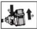
Assembling the guard (See Fig. A)
- Install the correct Guard for the trimmer head. (Supplied)
- Secure the guard in place with the supplied screws and torx key.
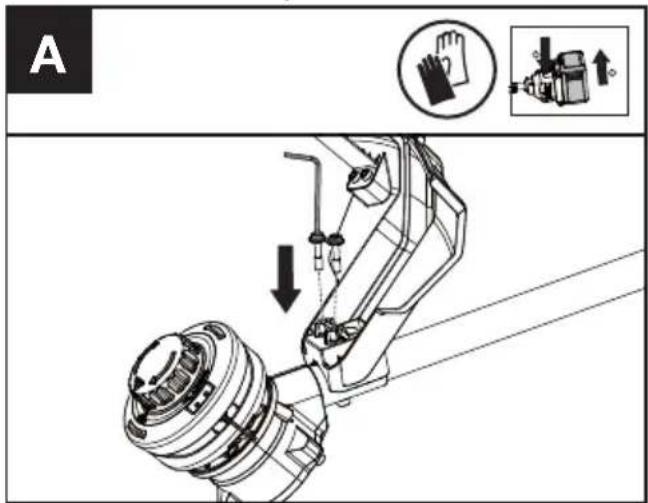
Assembling the bike handle (See Fig. B)
Place the bike handle (a) into the lower clamp (e). Place the upper clamp (b) over the lower clamp (e) and insert the two screws (d) and the clamp screw (c), but do not fully tighten. Tighten the two screws (d) until it is just possible to rotate the bike handle (a) in the clamp. Do not over tighten. Finally, tighten the clamp screw (c). Ensure that the bike handle is fully clamped. It should not move during the trimmer head bump operation.
Adjusting the harness (See Fig. C)
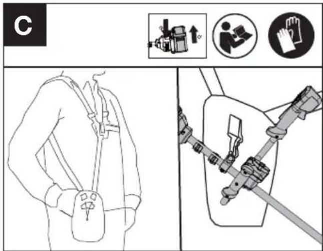
Adjust the length of harness strap to make it comfortable during operation while connecting the hip pad to the trimmer.
Balancing the trimmer (See Fig. D)
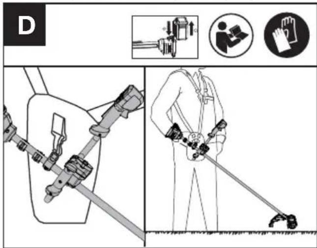
Put on the harness and connect hip pad to the trimmer. Let the trimmer hang on the harness until it stops moving (the trimmer head should be just hovering above the ground).
NOTE: Adjust the connection between the hip pad and trimmer if the trimmer is not properly balanced.
OPERATION:
Adjusting the bike handle (See Fig. E)
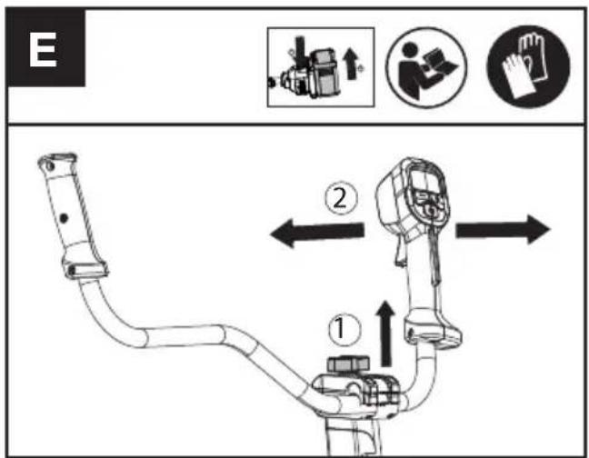
- Loosen the clamp bolt and adjust the bike handle to find the suitable position. (See Fig.E)
- Tighten the clamp bolt until the handle cannot be moved.
Installing & removing the battery pack (See Fig. F1, F2)
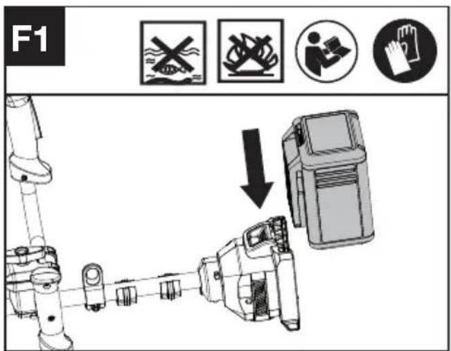
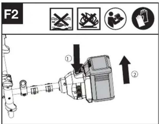
- Slide the battery pack into the battery compartment until you hear a click.
- Press the battery release button to release battery pack from your tool.
TESTING THE TRIMMER AND BATTERY (See Fig. F3)
Checking the controls
Operator Presence Switch and Throttle Trigger
- Remove the battery.
- Try to press the Throttle Trigger. If the Throttle Trigger can be pressed without pushing the Operator Presence Switch, the Operator Presence Switch is defective. Stop using the trimmer and contact the service agent.
- Push the Operator Presence Switch first, then press the Throttle Trigger.
- Release the Throttle Trigger and the Operator Presence Switch. If the Throttle Trigger or the Operator Presence Switch is stuck and cannot spring back to its original position. Stop using the trimmer and contact the service agent.
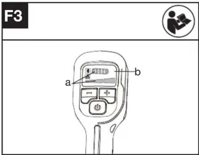
Checking the display
- Insert the battery.
- Hold and press the on/off button.
The product is switched on when the LED (a) is lit.
The product is switched off when the LED (a) is out.
- Push the Operator Presence Switch first, then press the Throttle Trigger to start the machine. The Trimmer Head rotates.
- If the warning indicator (b) lights up or is flashing, refer to Troubleshooting for solutions.
- Release the Throttle Trigger. The Trimmer Head stops rotating after a short delay. If the Trimmer Head continues to rotate, remove the battery and contact the service agent.
Starting the trimmer (See Fig. G1, G2)
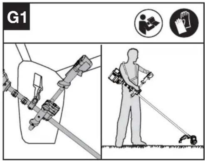
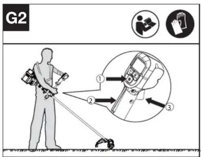
- Connect the trimmer to the hip pad hook.
- Hold the trimmer firmly with your right hand on the control handle and your left hand on the left side bike handle - wrap your thumbs around the handles to ensure a good grip.
- Hold and press the on/off button until the green LED is lit. The green LED shows the power level.
- Press the Operator Presence Switch first, then press the Throttle Trigger to start the machine. The green LED for start/stop indication goes off after 5 seconds and the product needs to be restarted.
NOTE: The Operator Presence Switch is designed to prevent accidental operation. When you press the Operator Presence Switch it releases the Throttle Trigger.
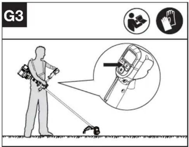
Selecting the speed (See Fig. G3)
Power Levels can be selected depending on the application. Use the +/- to control the speed, which is as indicated by the LEDs. The higher the power level, the faster the tool runs.
Stopping the trimmer
Release the Throttle Trigger to stop the machine.
WARNING! The cutting head continues to rotate after the cutter has been switched off; wait until it has completely stopped then lay down the tool.
Bump-line feed system (See Fig. H)
The trimmer is equipped with a bump-line system. Just bump the trimmer head while the machine is running, new line will feed out.

Cutting Tips (See Fig. I)

- Swing the trimmer from side to side across the area to be cut.
- Use the tip of the cutting line to do trimming; do not force the trimmer head into uncut grass.
- Wire and picket fences may cause extra cutting line wear and breakage. Stone and brick walls, curbs, and wood may wear cutting line rapidly.
- Avoid trees and shrubs. Tree bark, wood moldings, siding, and fence posts can easily be damaged by the cutting line.
- The selected power level affects the battery's runtime. The lower the power level, the longer the runtime. It is recommended to use the lowest power level unless in worse cutting condition.
For Battery tools
The recommended ambient temperature range for discharging is -20 °C\~45 °C (-4 °F\~113 °F).
The recommended ambient temperature range for the charging system during charging is -5 °C\~45 °C (23 °F\~113 °F).
TRANSPORTATION
Transporting the trimmer
- Switch off the trimmer and remove the battery.
- When transporting your trimmer by hand, hold the middle of the shaft with the cutting head to the rear and make sure that your machine is parallel to the ground.
- When transporting your trimmer in a vehicle, secure and position it to prevent movement or damage.
Transporting the battery
- Ensure the battery is in a safe condition.
- Use non-conductive packaging when transporting the battery.
- The contained Li-Ion batteries are subject to the dangerous goods legislation requirements.
Transport batteries only when the battery housing is undamaged. Pack up the batteries in such a manner that cannot move around in the packaging.
MAINTENANCE

WARNING! Always remove battery before conducting any maintenance on the
trimmer.
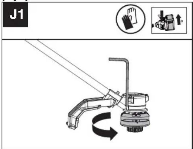
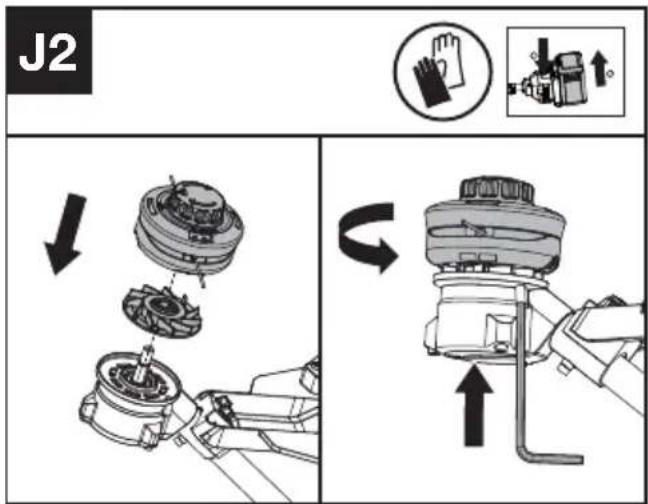
Replacing the trimmer head (See Fig. J1, J2)

WARNING! Use of wire or metal-reinforced line is not authorized and could be
extremely dangerous. Use only the cutting line recommended in this manual, in combination with the recommended debris guard.
WARNING! A damaged or loose cutting attachment head may vibrate, crack, break or come off the trimmer, which may result in serious or fatal injury or property damage. Make sure the trimmer head are properly and securely tightened and in good condition before starting work.
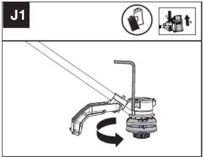
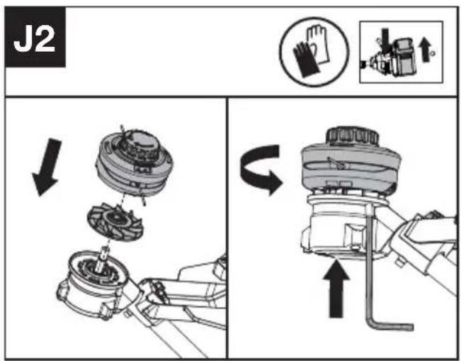
- Insert the torx key into the hole and rotate the trimmer head clockwise to remove it.
- Fit the Fan and the new cutting head. Insert the torx key into the hole and rotate the trimmer head counterclockwise until it stops in a locked position.

WARNING: When installing the Fan, ensure that the side with the "Outside" indicator is
facing outward.
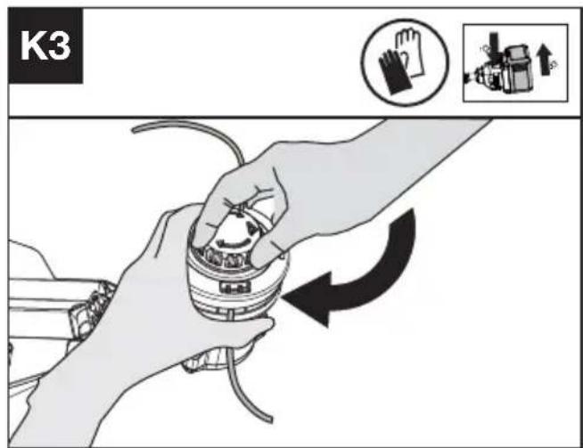
Winding the line (See Fig. K1, K2, K3)
- Rotate the spool cap until the two triangle icons are aligned. (See Fig. K1)
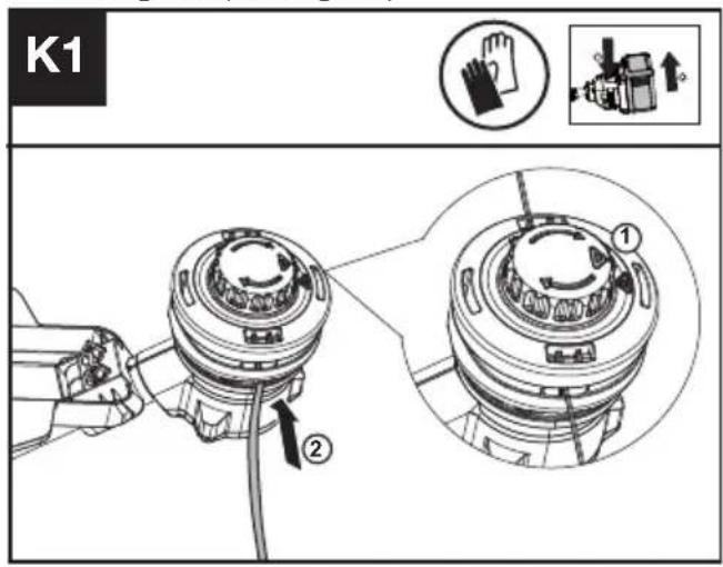
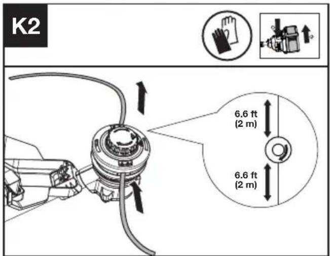
- Insert the replacement line through the eyelet (Line In) and feed it out through the other eyelet. Ensure both ends of the line are even on each end of the trimmer head (recommended
2 m (6.6 ft)) and cut the line. (See Fig. K2)
- Turn the dial clockwise to wind the line around the spool until about 16 cm (6") remains on either side. (See Fig. K3)
CLEANING
- Switch off the trimmer and remove the battery.
- Do not use aggressive detergents or solvents. Clean the machine after use with a damp cloth dipped in mild detergent.
- Keep battery connection free of dirt and debris, and clean with a soft and dry brush or cloth.
- Do not spray water onto the motor and electrical components.
- Do not use pressure washer to clean your machine.
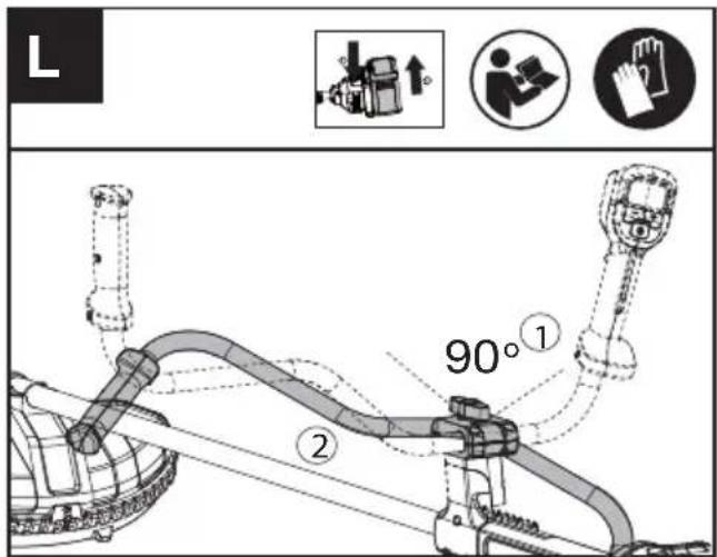
STORAGE
- Remove the battery pack from the trimmer before storage.
- Loosen the clamp bolt until the bike handle be moved. Rotate the bike handle 90° in a clockwise position and fold it down. Tighten the clamp bolt until the handle cannot be moved. (See Fig. L)
- If the machine becomes wet in the rain during operation, the machine and the battery should be dried before storing or charging. Remove the battery and reinsert it if the machine fails to turn on.
- Store the trimmer and the battery in a dry and secure place that is inaccessible to children and other unauthorized people.
Remove the cutting attachment if it will not be used for a long time.
- Store the battery only within a temperature range between 5^ C ( 41^ F) and 25^ C ( 77^ F). As an example, do not leave the battery in the car in summer time.
TROUBLESHOOTING
The following table gives problems and actions that you can perform if your machine does not operate correctly.

WARNING: Switch the machine off and remove the battery prior to any troubleshooting.
TRIMMER
| Problems Possible | Causes Corrective Action | |
| Battery indicator LED flashing | Low battery voltage. Charge the battery. | |
| Error LED flashing Overload. | The cutting attachment is jammed. | |
| Temperature issue. Let the product cool down. | ||
| The Throttle Trigger and the start/stop button are pressed at the same time. | Release Throttle Trigger. Perform the starting sequence again. | |
| Other problems | Contact Service Agent | |
| The product does not start Debris in the battery connectors. | Clean the battery connectors with compressed air or a soft brush. | |
| Agent. | ||
| Trimmer runs intermittently The battery is not fully inserted to the machine. | Insert the battery fully. | |
| Contact Service Agent. | ||
| Excessive vibrations/ noise. Line balance issue. Rewind the line. | ||
| Replace cutting attachment. Machine defective. Contact Service Agent. | ||
BATTERY
| Problems Possible | Causes Corrective Action | |
| Error LED lit The battery is discharged | Charge the battery. If battery fails to charge, contact your Service Agent. | |
| Temperature issue. Use the battery in surroundings where temperatures are between -5°C and 45°C (23°F to 113°F) for charge; -20°C to 45°C (-4°F to 113°F) for discharge. | ||
| Others Contact your Service Agent. |
TECHNICAL DATA
Type Designation: KC111 KC111.X (1-designation of machinery, representative of Cordless Grass Trimmer)
** X=1-999, A-Z, M1-M9 they are only used for different customers, there are no safety relevant changes between these models.
*** Voltage measured without workload. Initial battery voltage reaches maximum of 60 volts. Nominal voltage is 54 volts.
| KC111 KC111.X ** | |
| Voltage | 60 V --- MAX *** |
| Cutting speed | 4500 / 5000 /5500 rpm |
| Cutting diameter | 42 cm |
| Line diameter | 2.4 mm /2.7 mm nylon line |
| Degree of protection IPX 4 | |
| Machine weight (Bare tool) | 3.7 kg |
SUGGESTED BATTERIES AND CHARGERS
| Battery Capacity Charger Amperage | |||
| KAC804 4.0 Ah | KAC840 30 A | ||
| KAC810(With Backpack Harness and Weight Kit) | 11.0 Ah | ||
We recommend that you purchase your accessories from the same Dealer that sold you the tool. Refer to the accessory packaging for further details. Your Dealer can assist you and offer advice.
TECHNICAL DATA FOR BATTERY PACK (OPTIONAL)
| Frequency bands for Bluetooth 2400-2483.5 MHz | ||
| EN | Maximum Output Power for Bluetooth | 8 dBm |
COMBINATIONS OF CUTTING ATTACHMENTS, DEFLECTORS, AND CARRYING SYSTEMS
| Cutting attachment Debris guard Barrier bar Carrying system | |||
| - 4" Trimmer head- 5" Trimmer head(Optional, not included) | - compact trimmerhead guard (KAC184) | - Optional | - Shoulder strap- Backpack batteryHarness |
| - Knife blade (KAC171) | - compact blade guard(KAC185) | - Required | |
NOISE INFORMATION
| A weighted sound pressure L | _pA = 77.3 dB(A) |
| K_pA | 3.0 dB(A) |
| A weighted sound power L | _wA = 90.84 dB(A) |
| K_wA | 4.07 dB(A) |
| Wear ear protection. | |
VIBRATION INFORMATION
Typical weighted vibration a _h < 2.5 m/s^2
Uncertainty K = 1.5 m/s^2
WARNING: The vibration emission value during actual use of the power tool can differ from the declared value depending on the ways in which the tool is used dependant on the following examples and other variations on how the tool is used:
How the tool is used and the materials being cut or drilled.
The tool being in good condition and well maintained The use the correct accessory for the tool and ensuring it is sharp and in good condition.
The tightness of the grip on the handles and if any anti vibration accessories are used.
And the tool is being used as intended by its design and these instructions.
This tool may cause hand-arm vibration syndrome if its use is not adequately managed.
WARNING: To be accurate, an estimation of exposure level in the actual conditions of use should also take account of all parts of the operating cycle such as the times when the tool is switched off and when it is running idle but not actually doing the job. This may significantly reduce the exposure level over the total working period.
Helping to minimise your vibrati on exposure risk.
ALWAYS use sharp chisels, drills and blades
Maintain this tool in accordance with these instructions and keep well lubricated (where appropriate)
If the tool is to be used regularly then invest in anti vibration accessories.
Plan your work schedule to spread any high vibration tool use across a number of days.
ENVIRONMENTAL PROTECTION
Waste electrical products must not be disposed of with household waste. Please recycle where facilities exist. Check with your local authorities or retailer for recycling advice.
DECLARATION OF CONFORMITY
We,
Positec Germany GmbH
Postfach 680194, 50704 Cologne, Germany
On behalf of Positec declare that the product
Description Cordless Grass Trimmer
Type KC111 KC111.X (1-designation of machinery, representative of Cordless Grass Trimmer)
Function cutting grass and similar soft vegetation and for trimming grass edges
Complies with the following Directives:
2006/42/EC, 2014/30/EU, 2011/65/EU & (EU)
2015/863, 2000/14/EC amended by 2005/88/EC
2000/14/EC amended by 2005/88/EC:
- Conformity Assessment Procedure as per
- Measured Sound Power Level
- Declared Guaranteed Sound Power Level
Annex VI
94.9 dB (A)
96 dB (A)
The notified body involved
Standards conform to
EN 62841-1, FprEN IEC
62841-4-4:2020+FprAA:2021-02, EN 62233, EN
ISO 3744, EN IEC 55014-1, EN IEC 55014-2, EN
IEC 63000
The person authorized to compile the technical file,
Name Marcel Filz
Address Positec Germany GmbH
Postfach 680194, 50704 Cologne, Germany

2024/02/04
Allen Ding
Deputy Chief Engineer, Testing & Certification
Positec Technology (China) Co., Ltd
18, Dongwang Road, Suzhou Industrial
Park, Jiangsu 215123, P. R. China
DECLARATION OF CONFORMITY
We,
Positec (UK & Ireland) Ltd
PO Box 6242, Newbury, RG14 9LT, UK
On behalf of Positec declare that the product
Description Cordless Grass Trimmer
Type KC111 KC111.X (1-designation of machinery, representative of Cordless Grass Trimmer)
Function cutting grass and similar soft vegetation and for trimming grass edges
Complies with the following regulations:
Supply of Machinery (Safety) Regulations 2008
Electromagnetic Compatibility Regulations 2016
The Restriction of the Use of Certain Hazardous
Substances in Electrical and Electronic
Equipment Regulations
Noise Emission in the Environment by Equipment for Use Outdoors Regulations
- Conformity Assessment Procedure as per SCHEDULE 9
- Measured Sound Power Level 94.9 dB (A)
- Declared Guaranteed Sound Power Level 96 dB (A)
The notified body involved
Standards conform to
BS EN 62841-1, FprBS EN IEC
62841-4-4:2020+FprAA:2021-02, BS EN 62233,
BS EN ISO 3744, BS EN IEC 55014-1, BS EN IEC
55014-2,EN IEC 63000
The person authorized to compile the technical file,
Name Jim Kirkwood
Address Positec (UK & Ireland) Ltd,
PO Box 6242, Newbury, RG14 9LT, UK


2024/02/04
Allen Ding
Deputy Chief Engineer, Testing & Certification
Positec Technology (China) Co., Ltd
18, Dongwang Road, Suzhou Industrial
Park, Jiangsu 215123, P. R. China
INHALTSVERZEICHNIS
Einführung....19
Komponenten....20
KOMPONENTEN
18, Dongwang Road, Suzhou Industrial
Park, Jiangsu 215123, P. R. China
SOMMAIRE
Introduction....36
LISTE DES COMPOSANTS
- BLOC DE BATTERIE *
- BOUTON DE DÉVERROUILLAGE DE LA BATTERIE
- POINT DE FIXATION DU HARNAIS
- POIGNÉE
- COMMUTATEUR DE PRÉSENCE D'OPÉRATEUR
- MANETTE DES GAZ
- SUPPORT DE BANDOULIÈRE
- BOULON DE BLOCAGE
- ÉCRAN D'AFFICHAGE
- BOUTON DE CONTRÔLE DE LA VITESSE
- BOUTON MARCHE/ARRÊT
- ARBRE
-
ASSEMBLAGE DE LA PROTECTION
-
TÊTE DE COUPE
- COUVERCLE DE BOBINE
- BOBINE
- LOQUET DE DÉVERROUILLAGE DE COUVERCLE
- ŒILLET
- VENTILATEUR
- BANDOULIÈRE
- BOUCLE DE HARNAIS
- PROTÈGE-HANCHE
- CLÉ TORX
INFORMATIONS RELATIVES AU BRUIT
INFORMATIONS RELATIVES AUX VIBRATIONS
18, Dongwang Road, Suzhou Industrial
Park, Jiangsu 215123, P. R. China
INDICE
Introduzione....53
Elencocomponenti....54
ELEMENTI DELL'APPARECCHIO
- PACCO BATTERIA *
- PULSANTE DI RILASCIO DELLA BATTERIA
- PUNTO DI ATTACCO DELL'IMBRACATURA
- IMPUGNATURA
- INTERRUTTORE DI PRESENZA DELL'OPERATORE
- GRILLETTO DELL'ACCELERATORE
- MANUBRIO
- BULLONE DI FISSAGGIO
- SHERMO DEL DISPLAY
- PULSANTE DI CONTROLLO DELLA VELOCITÀ
- PULSANTE ON/OFF
- ASTA
-
MONTAGGIO DELLA PROTEZIONE
-
TESTINA TAGLIABORDI
- COPRI BOBINA
- BOBINA
- CHIUSURA DI RILASCIO DEL CAPPUCCIO
- OCCHIELLO
- VENTOLA
- TRACOLLA
- FIBBIA PER IMBRACATURA
- CUSCINETTO PER FIANCHI
- CHIAVE TORX
PER GLI UTENSILI A BATTERIA
18, Dongwang Road, Suzhou Industrial
Park, Jiangsu 215123, P. R. China
ÍNDICE
Introducción....69
Lista de componentes....70
18, Dongwang Road, Suzhou Industrial
Park, Jiangsu 215123, P. R. China
ÍNDICE
Introdução....85
Lista de componentes....86
PARA FERRAMENTAS ELÉTRICAS
18, Dongwang Road, Suzhou Industrial
Park, Jiangsu 215123, P. R. China
INHOUDSOPGAVE
Inleiding....101
DRIE SNELHEIDSINSTELLINGEN
- ACCUPACK *
- ACCU-ONTGRENDELKNOP
- BEVESTIGINGSPUNT VOOR HARNAS
- HANDGREEP
- BEDIENINGSAANWEZIGHEIDSSCHAKELAAR
- GASHENDEL
- FIETSHANDVAT
- KLEMBOUT
- BEELDSCHERM
- SNELHEIDSREGELKNOP
- AAN/UIT-KNOP
- SCHACHT
- BESCHERMKAP
| 14. TRIMMERKOP |
| 15. SPOELKAP |
| 16. SPOEL |
| 17. KAPONTGRENDELING |
| 18. HANGOOG |
| 19. VENTILATOR |
| 20. SCHOUDERRIEM |
| 21. HARNASGESP |
| 22. HEUPKUSSEN |
| 23. TORX-SLEUTEL |
VOOR GEREEDSCHAP MET ACCU'S
2015/863, 2000/14/EC amended by 2005/88/EC
18, Dongwang Road, Suzhou Industrial
Park, Jiangsu 215123, P. R. China
CUPRINS
Introducere....134
Technical diagram of a mechanical device with numbered parts and close-ups of internal components
LISTA DE COMPONENTE
- ACUMULATOR *
- BUTON DE ELIBERARE A ACUMULATORULUI
- PUNCT DE FIXARE A HAMULUI
- ZONĂ DE PRINDERE MANUALĂ
- COMUTATOR PENTRU PREZENTA UTILIZATORULUI
- BUTONUL DE ACCELERATIE
- GHIDON
- BOLT DE PRINDERE
- AFIŞAJ
- BUTON DE CONTROL AL VITEZEI
- BUTON DE PORNIRE/OPRIRE
- AX
-
ANSAMBLU DE PROTECTIE
-
CAP DE TĂIERE
- CAPAC BOBINĂ
- BOBINĂ
- OPRITOR ELIBERARE CAPAC
- ORIFICIU
- VENTILATOR
- CUREA DE UMĂR
- CATARAMĂ PENTRU HAM
- PAD PENTRU ŞOLD
- CHEIE HEXAGONALĂ
[EMFRODHVSXQ]äWRDUHVDXIODWHPSHUDWXULGI
SODMHL□GH□WHPSHUDWXUL□VSHFL□FDWH□SRDWH
ODGHWHULRUDUHDDFXPXODWRUXOXLúLÍODÍFU
a) Service-ul uneltei electrice trebuie efectuat de persoane calificate,
folosind doar piese de schimb
originale. FHVW OXFUX YD DVLJXUD IRORVLUHI
FRQWLQXDUH□D□XQHOWHL□HOHFWULFH□vQ□VLJXU
Diagram illustrating a person using a tool to clean a slope, with corresponding safety icons and a magnified inset showing the tool's cross-section.
18, Dongwang Road, Suzhou Industrial
Park, Jiangsu 215123, P. R. China
SPIS TREŚCI
Wprowadzenie....151
Technical diagram of a mechanical device with numbered parts and exploded view, including control panel and component assembly.
LISTA KOMPONENTÓW
- PAKIET BATERII *
- PRZYCISK ZWALNIANIA BATERII
- PUNKT MOCOWANIA UPRZĘŻY
- UCHWYT RĘCZNY
- PRZEŁĄCZNIK WYKRYWANIA OBECNOŚCI OPERATORA
- WYZWALACZ PRZEPUSTNICY
- KIEROWNICA
- ŚRUBA ZACISKOWA
- EKRAN WYŚWIETLACZA
- PRZYCISK KONTROLI PREDKOŚCI
- PRZYCISK ON/OFF (WŁĄCZ/WYŁĄCZ)
- WAL
-
ZESPÓŁ OSŁON
-
GŁOWICA TRYMERA
- ZATYCZKA SZPULI
- SZPULA
- ZATRZASK ZWALNIANIA ZATYCZKI
- OCZKO
- WENTYLATOR
- PASEK NA RAMIĘ
- KLAMRA UPRZĘŻY
- OCHRANIACZ NA BIODRA
- KLUCZ TORX
TRAWY/ZAROŚLI I PIŁ TARCZOWYCH
Diagram illustrating a person using a tool to clean a machine, with icons and a magnified view of the device's internal structure.
18, Dongwang Road, Suzhou Industrial
Park, Jiangsu 215123, P. R. China
OBSAH
Úvod....168
Technical diagram of a mechanical device with numbered parts and close-up insets for identification.
SEZNAM KOMPONENT
- AKUMULÁTOR *
- TLAČÍTKO UVOLNĚNÍ BATERIE
- UCHYCENÍ POPRUHU
- RUKOJEŠT
- SPÍNAČ PŘÍTOMNOSTI OBSLUHY
- SPOUŠT ŠKRTICÍ KLAPKY
- RÍDÍTKA
- UPÍNACÍ ŠROUB
- OBRAZOVKA DISPLEJE
- TLAČÍTKO REGULACE RYCHLOSTI
- HLAVNÍ VYPÍNAČ
- HŘÍDEL
-
SESTAVA KRYTU
-
SEKACÍ HLAVA
- KRYT CÍVKY
- CÍVKA
- UVOLŇOVACÍ ZÁPADKA KRYTU
- OČKO
- VĚTRÁK
- RAMENNÍ POPRUH
- SPONA POSTROJE
- KYČELNÍ PODLOŽKA
- TORX KLÍČ (HVĚZDIČKOVÝ KLÍČ)
Diagram illustrating a person using a tool to clean a machine, with icons and a magnified inset showing the mechanical setup.
INFORMACE TÝKAJÍCÍ SE HLUČNOSTI
18, Dongwang Road, Suzhou Industrial Park, Jiangsu 215123, P. R. China
OBSAH
Úvod....184
Technical diagram of a mechanical device with numbered parts and close-up insets for identification.
=2=1\0□6Ôÿ\67Ì
-
%\$7e5,29ë% / 2. *
-
7/\ÿ,'/2□1\□892Ë1(1,(□%\$7e5,(
-
BOD UPEVNENIA POSTROJA
-
58.29bh
-
63 1 1 35 1 7201267, 2%6/8+<
-
ä.57,\&\□./\3.\
-
%,&<./29e□5,\$','/2
-
83 ^1 &,\6.587.\
-
OBRAZOVKA DISPLEJA
-
7/\ÿ,'/2□29/É\1,\$□5ë&+/267,
-
7/\ÿ,'/2□=\3□9<3
-
+5,\$'(E
-
=267\9\□2&+5\$11e+2□.5<78
-
VYŽÍNACIA HLAVICA
- UZÁVER CIEVKY
- CIEVKA
- ZÁPADKA NA UVOL'NENIE VIEČKA
- OČKO
- VENTILÁTOR
- RAMENNÝ POPRUH
- PRACKA POSTROJA
- BEDROVÁ PODLOŽKA
- TORX KL'ÚČ
Diagram illustrating a person using a tool to clean a machine, with icons representing different methods and a magnified inset showing the mechanical setup.
Positec Technology (China) Co., Ltd 18, Dongwang Road, Suzhou Industrial Park, Jiangsu 215123, P. R. China
KAZALO VSEBINE
Uvod....201
Sestavni deli....202
Varnost izdelka....204
Sestavljanje in delovanje....208
Transport....212
Vzdrževanje....212
Čiščenje....213
Shranjevanje....213
Technical diagram of a mechanical device with numbered parts and exploded view, including control panel and component assembly.
SESTAVNI DELI
- BATERIJSKI SKLOP *
- GUMB ZA SPROSTITEV BATERIJE
- PRITRDILNO MESTO ZA PAS
- OPRIJEM
- STIKALO ZA PRISOTNOST UPRAVLJAVCA
- SPROŽILEC PLINA
- KOLESARSKI ROČAJ
- OBJEMNI VIJAK
- PRIKAZOVALNI ZASLON
- GUMB ZA NADZOR HITROSTI
- GUMB ZA VKLOP/IZKLOP
- GRED
-
SKLOP VAROVALA
-
GLAVA OBREZOVALNIKA
- POKROVČEK MOTKA
- MOTEK
- ZAPAH ZA SPROSTITEV POKROVČKA
- OBROČEK
- VENTILATOR
- NARAMNI PAS
- ZAPONKA ZA PAS
- BOČNA BLAZINICA
- TORX KLJUČ
Diagram illustrating a person using a tool to measure a machine, with corresponding icons and a magnified view of the tool's internal structure.
18, Dongwang Road, Suzhou Industrial
Park, Jiangsu 215123, P. R. China
SADRŽAJ
Uvod....217
Popis komponenti....218
Sigurnost proizvoda....220
Sastavljanje i rad....224
Transport....227
Održavanje....227
Čišćenje....229
Skladištenje....229
Otklanjanje poteškoća....230
Tehnički podaci....230
Zaštita okoliša....232
Izjava o sukladnosti....232
UVOD
Poštovani,
Technical diagram of a mechanical device with numbered parts and close-up insets for identification.
POPIS KOMPONENTI
- BATERIJSKI MODUL *
- GUMB ZA OTPUŠTANJE BATERIJE
- TOČKA PRIČVRŠĆIVANJA POJASA
- DRŠKA ZA RUKU
- PREKIDAČ PRISUTNOSTI RUKOVATELJA
- AKTIVATOR GASA
- UPRAVLJAČKA RUČKA
- STEZNI VIJAK
- ZASLON PRIKAZA
- GUMB ZA KONTROLU BRZINE
- GUMB ZA UKLJUČIVANJE/ISKLJUČIVANJE
-
OSOVINA
-
SKLOP ŠTITNIKA
- GLAVA TRIMERA
- POKLOPAC KALEMA
- KALEM
- ZASUN ZA OTPUŠTANJE POKLOPCA
- UŠICA
- VENTILATOR
- NARAMENICA
- KOPČA ZA POJAS
- JASTUČIĆ ZA BOK
- TORX KLJUČ
* Standardna isporuka ne obuhvaća sav ilustriran ili opisan pribor.
ORIGINALNE UPUTE ZA RAD SIGURNOST PROIZVODA UOBIČAJENA SIGURNOSNA UPOZORENJA ZA ELEKTRIČNE ALATE

UPOZORENJE Pročitajte sva sigurnosna upozorenja, upute,
ilustracije i specifikacije koje se isporučuju s ovim električnim alatom. Nepoštivanje dolje navedenih uputa može uzrokovati električni udar, požar i/ili ozbiljne ozljede.
Illustration showing a person using a tool to clean a machine, with icons for cleaning and safety operations.
ZA BATERIJSKE ALATE
Preporučeni raspon temperature okoline za pražnjenje je -20 °C\~45 °C (-4 °F\~113 °F). Preporučeni raspon temperature okoline za sustav punjenja tijekom punjenja je -5 °C\~45 °C (23 °F\~113 °F).
TRANSPORT
Prenošenje trimera
- Isključite trimer i izvadite bateriju.
- Kad trimer prenosite ručno, sredinu osovine s reznom glavom držite sa stražnje strane i pripazite da stroj bude paralelan sa tlom.
- Kad prevozite trimer u vozilu, osigurajte ga i postavite tako da spriječite njegovo pomicanje ili oštećenje.
Prenošenje baterije
- Osigurajte da je baterija u sigurnom stanju.
- Prilikom transporta baterije koristite neprovodnu ambalažu.
- Sadržane litij-ionske baterije podliježu zahtjevima zakona o opasnoj robi.
Baterije transportirajte samo ako je njihovo kućište neoštećeno. Zapakirajte baterije na način da se ne mogu pomicati u pakiranju.
ODRŽAVANJE
UPOZORENJE! Uvijek uklonite bateriju prije nego što započnete održavanje na trimeru.
ZAMJENA GLAVE TRIMERA (VIDI SL. J1, J2)

UPOZORENJE! Korištenje žice ili niti ojačane metalom nije dopušteno i biti izuzetno opasno. Koristite samo nit koja se preporučuje u ovimama, u kombinaciji s preporučenim kom od krhotina.

UPOZORENJE! Oštećena ili labava glava nastavka za rezanje može sati, puknuti, slomiti se ili otpasti sra, čime može doći do ozbiljnih ili onosnih ozljeda ili oštećenja imovine. Jerite je li glava trimera propisno i no pričvršćena i je li u dobrom stanju početka rada.
J1
J2 ↓ ←
NAMOTAVANJE NITI (VIDI SL. K1, K2, K3)
Technical diagram of a mechanical device with numbered parts and close-up insets for identification.
Illustration showing a person using a tool to clean a machine, with icons for cleaning and safety operations.
18, Dongwang Road, Suzhou Industrial
Park, Jiangsu 215123, P. R. China
SISÄLLYSLUETTELO
Johdanto....248
Komponenttiluettelo....249
Technical diagram of a mechanical device with numbered parts and close-up insets for identification.
KOMPONENTTILUETTELO
- AKKU *
- AKUN VAPAUTUSPAINIKE
- VALJAIDEN KIINNITYSPISTE
- OTEKAHVA
- KÄYTTÄJÄN LÄSNÄOLOKYTKIN
- KAASULIIPAISIN
- ETUKAHVA
- KIINNITYSRUUVI
- NÄYTTÖRUUTU
- NOPEUDEN SÄÄTÖPAINIKE
- ON/OFF-VIRTAKYTKIN
- VARSI
- SUOJUS
| 14. TRIMMERIPÄÄ |
| 15. KELAN KORKKI |
| 16. KELA |
| 17. KORKIN VAPAUTUSSALPA |
| 18. SILMUKKA |
| 19. TUULETIN |
| 20. OLKAHIHNA |
| 21. VALJAAT |
| 22. LONKKAPEHMUSTE |
| 23. TORX-AVAIN |
Diagram illustrating a person using a tool to clean a machine, with icons and a magnified view of the device's tip.
Transportation....273
Vedlikehold....273
Rengjøring....273
Lagring....274
Feilsøking....274
Technical diagram of a mechanical device with numbered parts and close-up insets for identification.
APPARATELEMENTER
- BATTERIPAKKE *
- UTL∅SERKNAPP FOR BATTERI
- FESTEPUNKT FOR SELE
- HÅNDGREP
- BRYTER FOR OPERAT∅RTILSTEDEVÆRELSE
- GASSBRYTER
- STYREHÅNDTAK
- KLEMMEBOLT
- SKJERM
- KNAPP FOR FARTSKONTROLL
- PÅ/AV-KNAPP
- SKAFT
| 13. VERNMONTERING |
| 14. KUTTEHODE |
| 15. SPOLEDEKSEL |
| 16. SPOLE |
| 17. LÅS FOR UTL∅SNING AV DEKSEL |
| 18. MALJE |
| 19. VIFTE |
| 20. SKULDERREM |
| 21. SELESPENNE |
| 22. HOFTEPUTE |
| 23. TORXN∅KKEL |
Diagram illustrating a person using a tool to clean a machine, with corresponding safety icons and a magnified view of the device's tip.
18, Dongwang Road, Suzhou Industrial
Park, Jiangsu 215123, P. R. China
INNEHÅLLSFÖRTECKNING
Introduktion....278
Komponenter....279
Produktsäkerhet....281
Transportation....288
Underhåll....288
Rengöring....289
Förvaring....289
Felsökning....290
Tekniska data....290
Miljöskydd....292
Technical diagram of a mechanical device with numbered parts and close-up insets for identification.
KOMPONENTER
- BATTERIPAKET *
- BATTERIETS FRIKOPPLINGSKNAPP
- FÄSTPUNKT FÖR SELEN
- HANDGREPP
- OPERATÖRS-NÄRVARO BRYTARE
- GASREGLAGE FÖR DRIFT
- CYKELHANDTAG
- KLÄMBULT
- SKÄRM
- KNAPP FÖR HASTIGHETSREGLERING
- PÅ/AV-KNAPP
- AXEL
- SKYDDSANORDNING
| 14. TRIMMERHUVUD |
| 15. SPOLLOCK |
| 16. SPOLE |
| 17. LÅSHAKE LOCK |
| 18. ÖGLA |
| 19. FLÄKT |
| 20. AXELREM |
| 21. SPÄNNSELE |
| 22. HÖFTSKYDD |
| 23. VRIDMOMENTNYCKEL |
H 100% (50%) 100% (50%) 100% (50%) 100% (50%) 100% (50%) 100% (50%) 100% (50%) 100% (50%) 100% (50%) 100% (50%) 100% (50%) 100% (50%) 99.99999999999999999999999999999999999999999999999999999999999999999999999999999999999999999999999999998888888888888888888888888888888888888888888888888888888888888888888888888888888888888888888888888888
Klipptips (Se Figur I)

Safety instruction diagram showing a person using a tool to clean a machine, with safety symbols and a magnified view of the device.
18, Dongwang Road, Suzhou Industrial
Park, Jiangsu 215123, P. R. China