
KC711.9 - Lawn mower KRESS - Free user manual and instructions
Find the device manual for free KC711.9 KRESS in PDF.

| Product type | Cordless self-propelled steel platform lawn mower |
| Brand | Kress |
| Model | KC711.9 |
| Nominal voltage | 54 V (max 60 V) |
| Cutting width | 51 cm |
| Cutting height | 25 – 115 mm |
| Cutting height positions | 8 |
| Maximum self-propelled speed | 6.4 km/h |
| Collection bag capacity | 88 L |
| Weight (tool only) | 42 kg |
| Platform material | Reinforced steel 1.8 mm |
| Protection rating | IPX4 |
| Runtime (with 11 Ah battery) | 70 min |
| Battery type | Li-Ion (recommended battery KAC810 11 Ah) |
| Cutting mode | Mulching, bagging, rear discharge |
| Cutting height adjustment | Lever on front and rear wheels |
| Safety functions | Automatic blade stop when control is released, On/Off switch, protection against accidental restart |
| Sound power level (LwA) | 95.3 dB(A) |
| Sound pressure level (LpA) | 80.7 dB(A) |
| Vibrations (ah) | < 2.5 m/s² |
| Connectivity | Bluetooth (band 2400-2483.5 MHz) |
| Blade maintenance | Sharpening or replacement every 50 h, tightening torque 25 Nm |
| Cleaning | Damp cloth and neutral detergent, do not spray water on motor |
| Storage | Dry place, battery between 5 and 25 °C, folding handles |
| Spare parts and repairability | Blade and battery replaceable, authorized after-sales service for repairs |
Frequently Asked Questions - KC711.9 KRESS
User questions about KC711.9 KRESS
0 question about this device. Answer the ones you know or ask your own.
Ask a new question about this device
Download the instructions for your Lawn mower in PDF format for free! Find your manual KC711.9 - KRESS and take your electronic device back in hand. On this page are published all the documents necessary for the use of your device. KC711.9 by KRESS.
USER MANUAL KC711.9 KRESS
natural_image
Side view of a Kress Commercial lawn mower (no visible text or symbols on the device body)| Commercial 60V 51cm Reinforced Steel Deck SP Mower | EN | P03 |
| Gewerblicher 60 V, 51 cm Stahl-Mähwerk SP Rasenmäher | D | P21 |
| Tondeuse auto-tractée commerciale à plateforme en acier 51 cm 60 V | F | P40 |
| Tosaerba commerciale 60V con piatto in acciaio da 51 cm | I | P59 |
| Cortacésped SP Comercial de 60V con cubierta de acero de 51 cm | ES | P77 |
| Cortador de relva comercial de 60 V e 51 cm com plataforma em aço e autopropulsão | PT | P95 |
| Commercial 60V 51cm stalen maaidek SP grasmaaier | NL | P113 |
| Ipari 60 V-os 51 cm-es önjáró fünyíró acél késházzal | HU | P131 |
| Maşină de tuns iarba cu autopropulsare, model comercial de 60 V 51 cm, cu carcasă de oțel | RO | P149 |
| Komercyjna kosiarka SP ze stalowym korpusem 51 cm 60 V | PL | P168 |
| 60 V sekačka na trávu Steel Deck s pojezdem a šířkou záběru 51 cm pro komerční účely | CZ | P186 |
| Komerčná 60 V, 51 cm samohybná kosačka s ocel'ovou plošinou | SK | P204 |
| Komercialna kosilnica SP z jekleno ploščo 60 V 51 cm | SL | P222 |
| Komercijalna 60V 51cm SP kosilica s čeličnim trupom | HR | P240 |
| Professionel 60 V 51 cm selvkørende plæneklipper med stålskjold | DK | P258 |
| Kaupalliseen käyttöön 60 V, 51 cm:n teräskannellinen SP-ruohonleikkuri | FIN | P276 |
| Kommersiell 60 V 51 cm-ståldekk SP gressklipper | NOR | P293 |
| Kommersiell 60V 51cm SP-gräsklippare med ståldäck | SV | P310 |
KC711 KC711.X
TABLE OF CONTENTS
Introduction....3
Component List....5
Product Safety....6
Assembly & Operation....9
Transportation....13
Maintenance....14
Cleaning....15
Storage....16
Troubleshooting....16
Technical Data....17
Environmental Protection....19
Declaration of Conformity....19
INTRODUCTION
Dear Customer,
Thank you for buying this Kress Commercial product. We are dedicated to developing high quality products to meet your commercial landscaping requirements.
The Kress brand is synonymous with premium quality service. Over the years of your product's life, if you have any questions or concerns about your product, please contact your dealer or our Customer Service Team for assistance.
We are confident you will enjoy working with your Kress product for years to come.
INTENDED USE
This product is intended for commercial lawn mowing.
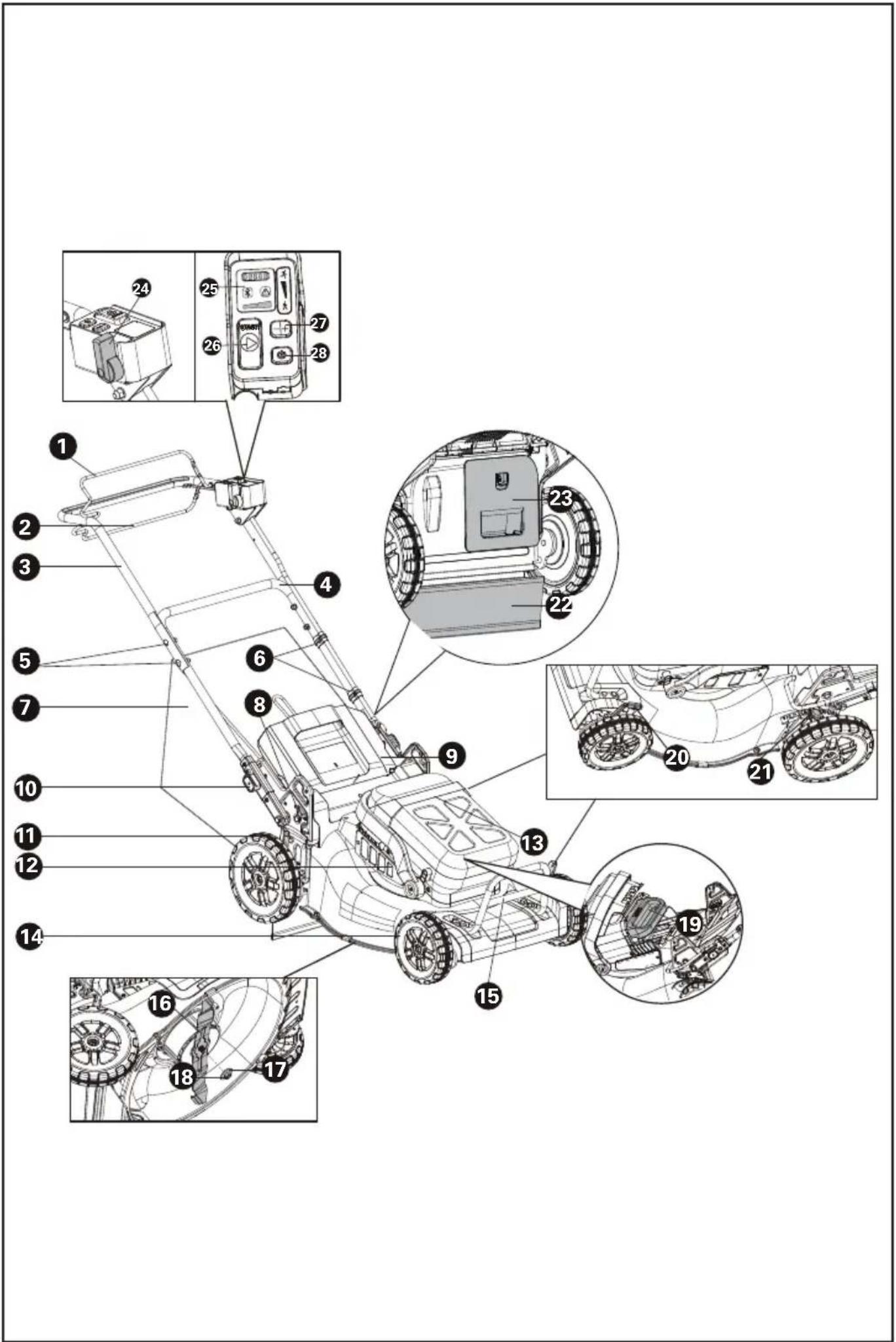
COMPONENT LIST
-
OPERATING BAIL (BLADE ENGAGEMENT)
-
SELF-PROPEL ENGAGEMENT BAIL
-
UPPER HANDLE
-
LOWER HANDLE
-
HANDLE FASTENERS
-
CABLE CLIP
-
GRASS COLLECTION BAG
-
FOLDING SWITCH
-
SAFETY FLAP
-
HANDLE HEIGHT ADJUSTMENT KNOB
-
REAR WHEEL
-
AIR FILTER
-
BATTERY COMPARTMENT COVER
-
FRONT WHEEL
-
MOTOR GUARD
-
BLADE
-
SPACER
-
BLADE BOLT
-
BATTRY PACK*
-
FRONT CUTTING HEIGHT ADJUSTMENT LEVER
-
REAR CUTTING HEIGHT ADJUSTMENT LEVER
-
RUBBER FLAP
-
MULCHING PLUG
-
SELF-PROPEL SPEED CONTROL
-
LED INDICATORS
-
CUTTING BLADE START BUTTON
-
CUTTING SPEED CONTROL
-
ON/OFF SWITCH
ORIGINAL INSTRUCTIONS PRODUCT SAFETY GENERAL POWER TOOL SAFETY WARNINGS

WARNING Read all safety warnings, instructions, illustrations and specifications provided with this power tool. Failure to follow all instructions listed below may result in electric shock, fire and/or serious injury.
Save all warnings and instructions for future reference.
The term "power tool" in the warnings refers to your mains-operated (corded) power tool or battery-operated (cordless) power tool.
1) Work area safety
a) Keep work area clean and well lit. Cluttered or dark areas invite accidents.
b) Do not operate power tools in explosive atmospheres, such as in the presence of flammable liquids, gases or dust. Power tools create sparks which may ignite the dust or fumes.
c) Keep children and bystanders away while operating a power tool. Distractions can cause you to lose control.
2) Electrical safety
a) Power tool plugs must match the outlet. Never modify the plug in any way. Do not use any adapter plugs with earthed (grounded) power tools. Unmodified plugs and matching outlets will reduce risk of electric shock.
b) Avoid body contact with earthed or grounded surfaces, such as pipes, radiators, ranges and refrigerators. There is an increased risk of electric shock if your body is earthed or grounded.
c) Do not operate the machine in rain or wet conditions. This may increase the risk of electric shock.
d) Do not abuse the cord. Never use the cord for carrying, pulling or unplugging the power tool. Keep cord away from heat, oil, sharp edges or moving parts. Damaged or entangled cords increase the risk of electric shock.
e) When operating a power tool outdoors, use an extension cord suitable for outdoor use. Use of a cord suitable for outdoor use reduces the risk of electric shock.
f) If operating a power tool in a damp location is unavoidable, use a residual current device (RCD) protected supply. Use of an RCD reduces the risk of electric shock.
3) Personal safety
a) Stay alert, watch what you are doing and use common sense when operating a power tool. Do not use a power tool while you are tired or under the influence of drugs, alcohol
or medication. A moment of inattention while operating power tools may result in serious personal injury.
b) Use personal protective equipment. Always wear eye protection. Protective equipment such as dust mask, non-skid safety shoes, hard hat, or hearing protection used for appropriate conditions will reduce personal injuries.
c) Prevent unintentional starting. Ensure the switch is in the off-position before connecting to power source and/or battery pack, picking up or carrying the tool. Carrying power tools with your finger on the switch or energising power tools that have the switch on invites accidents.
d) Remove any adjusting key or wrench before turning the power tool on. A wrench or a key left attached to a rotating part of the power tool may result in personal injury.
e) Do not overreach. Keep proper footing and balance at all times. This enables better control of the power tool in unexpected situations.
f) Dress properly. Do not wear loose clothing or jewellery. Keep your hair and clothing away from moving parts. Loose clothes, jewellery or long hair can be caught in moving parts.
g) If devices are provided for the connection of dust extraction and collection facilities, ensure these are connected and properly used. Use of dust collection can reduce dust-related hazards.
h) Do not let familiarity gained from frequent use of tools allow you to become complacent and ignore tool safety principles. A careless action can cause severe injury within a fraction of a second.
4) Power tool use and care
a) Do not force the power tool. Use the correct power tool for your application. The correct power tool will do the job better and safer at the rate for which it was designed.
b) Do not use the power tool if the switch does not turn it on and off. Any power tool that cannot be controlled with the switch is dangerous and must be repaired.
c) Disconnect the plug from the power source and/or remove the battery pack, if detachable, from the power tool before making any adjustments, changing accessories, or storing power tools. Such preventive safety measures reduce the risk of starting the power tool accidentally.
d) Store idle power tools out of the reach of children and do not allow persons unfamiliar with the power tool or these instructions to operate the power tool. Power tools are dangerous in the hands of untrained users.
e) Maintain power tools and accessories. Check for misalignment or binding of moving parts, breakage of parts and any other condition that may affect the power tool's operation. If damaged, have the power tool repaired before use. Many accidents are caused by poorly maintained power tools.
f) Keep cutting tools sharp and clean. Properly
maintained cutting tools with sharp cutting edges are less likely to bind and are easier to control.
g) Use the power tool, accessories and tool bits etc. in accordance with these instructions, taking into account the working conditions and the work to be performed. Use of the power tool for operations different from those intended could result in a hazardous situation.
h) Keep handles and grasping surfaces dry, clean and free from oil and grease. Slippery handles and grasping surfaces do not allow for safe handling and control of the tool in unexpected situations.
5) Battery tool use and care
a) Recharge only with the charger specified by the manufacturer. A charger that is suitable for one type of battery pack may create a risk of fire when used with another battery pack.
b) Use power tools only with specifically designated battery packs. Use of any other battery packs may create a risk of injury and fire.
c) When battery pack is not in use, keep it away from other metal objects, like paper clips, coins, keys, nails, screws or other small metal objects, that can make a connection from one terminal to another. Shorting the battery terminals together may cause burns or a fire.
d) Under abusive conditions, liquid may be ejected from the battery; avoid contact. If contact accidentally occurs, flush with water. If liquid contacts eyes, additionally seek medical help.
Liquid ejected from the battery may cause irritation or burns.
e) Do not use a battery pack or tool that is damaged or modified. Damaged or modified batteries may exhibit unpredictable behaviour resulting in fire, explosion or risk of injury.
f) Do not expose a battery pack or tool to fire or excessive temperature. Exposure to fire or temperature above 130 °C may cause explosion.
g) Follow all charging instructions and do not charge the battery pack or tool outside the temperature range specified in the instructions. Charging improperly or at temperatures outside the specified range may damage the battery and increase the risk of fire.
6) Service
a) Have your power tool serviced by a qualified repair person using only identical replacement parts. This will ensure that the safety of the power tool is maintained.
b) Never service damaged battery packs. Service of battery packs should only be performed by the manufacturer or authorized service providers.
LAWNMOWER SAFETY WARNINGS
a) Do not use the lawnmower in bad weather conditions, especially when there is a risk of
lightning. This decreases the risk of being struck by lightning.
b) Thoroughly inspect the area for wildlife where the lawnmower is to be used. Wildlife may be injured by the lawnmower during operation.
c) Thoroughly inspect the area where the lawnmower is to be used and remove all stones, sticks, wires, bones, and other foreign objects. Thrown objects can cause personal injury.
d) Before using the lawnmower, always visually inspect to see that the blade and the blade assembly are not worn or damaged. Worn or damaged parts increase the risk of injury.
e) Check the grass catcher frequently for wear or deterioration. A worn or damaged grass catcher may increase the risk of personal injury.
f) Keep guards in place. Guards must be in working order and be properly mounted. A guard that is loose, damaged, or is not functioning correctly may result in personal injury.
g) Keep all cooling air inlets clear of debris. Blocked air inlets and debris may result in overheating or risk of fire.
h) While operating the lawnmower, always wear non-slip and protective footwear. Do not operate the lawnmower when barefoot or wearing open sandals. This reduces the chance of injury to the feet from contact with the moving blade.
i) While operating the lawnmower, always wear long trousers. Exposed skin increases the likelihood of injury from thrown objects.
j) Do not operate the lawnmower in wet grass. Walk, never run. This reduces the risk of slipping and falling which may result in personal injury.
k) Do not operate the lawnmower on excessively steep slopes. This reduces the risk of loss of control, slipping and falling which may result in personal injury.
I) When working on slopes, always be sure of your footing, always work across the face of slopes, never up or down and exercise extreme caution when changing direction. This reduces the risk of loss of control, slipping and falling which may result in personal injury.
m) Use extreme caution when reversing or pulling the lawnmower towards you. Always be aware of your surroundings. This reduces the risk of tripping during operation.
n) Do not touch blades and other hazardous moving parts while they are still in motion. This reduces the risk of injury from moving parts.
o) When clearing jammed material or cleaning the lawnmower, make sure all power switches are off and the battery pack is disconnected. Unexpected operation of the lawnmower may result in serious personal injury.
SAFETY WARNINGS FOR BATTERY PACK
a) Do not dismantle, open or shred cells or
battery pack.
b) Do not short-circuit a battery pack. Do not store battery packs haphazardly in a box or drawer where they may short-circuit each other or be short-circuited by conductive materials. When battery pack is not in use, keep it away from other metal objects, like paper clips, coins, keys, nails, screws or other small metal objects, that can make a connection from one terminal to another. Shorting the battery terminals together may cause burns or a fire.
c) Do not expose battery pack to heat or fire. Avoid storage in direct sunlight.
d) Do not subject battery pack to mechanical shock.
e) In the event of battery leaking, do not allow the liquid to come into contact with the skin or eyes. If contact has been made, wash the affected area with copious amounts of water and seek medical advice.
f) Keep battery pack clean and dry.
g) Wipe the battery pack terminals with a clean dry cloth if they become dirty.
h) Battery pack needs to be charged before use. Always refer to this instruction and use the correct charging procedure.
i) Do not maintain battery pack on charge when not in use.
j) After extended periods of storage, it may be necessary to charge and discharge the battery pack several times to obtain maximum performance.
k) Recharge only with the charger specified by Kress. Do not use any charger other than that specifically provided for use with the equipment.
I) Do not use any battery pack which is not designed for use with the equipment.
m) Keep battery pack out of the reach of children.
n) Retain the original product literature for future reference.
o) Remove the battery from the equipment when not in use.
p) Dispose of properly.
q) Do not mix cells of different manufacture, capacity, size or type within a device.
r) Keep the battery away from microwaves and high pressure.
USER MANUAL REQUIREMENTS FOR WIRELESS PRODUCT
a) Operation of this device is subject to the following two conditions:
(1) This device may not cause harmful interference, and
(2) this device must accept any interference received, including interference that may cause
undesired operation.
b) Caution: Changes or modifications to this unit not expressly approved by the party responsible for compliance could void the user's authority to operate the equipment.
c) NOTE: This equipment generates, uses and can radiate radio frequency energy and, if not installed and used in accordance with the instructions, may cause harmful interference to radio communications. However, there is no guarantee that interference will not occur in a particular installation. If this equipment does cause harmful interference to radio or television reception, which can be determined by turning the equipment off and on, the user is encouraged to try to correct the interference by one or more of the following measures:
- Reorient or relocate the receiving antenna.
- Increase the separation between the equipment and receiver.
- Connect the equipment into an outlet on a circuit different from that to which the receiver is connected.
- Consult the dealer or an experienced radio/TV technician for help.
SYMBOLS
 | To reduce the risk of injury, user must read instruction manual |
 | Warning |
 | WARNING – Beware of thrown objects – keep bystanders away |
 | WARNING – Keep hands and feet away from the blades |
 | WARNING – Disconnect battery before maintenance |
 | Blade continues to rotate after the machine is switched off. Wait until all machine components have completely stopped before touching them |
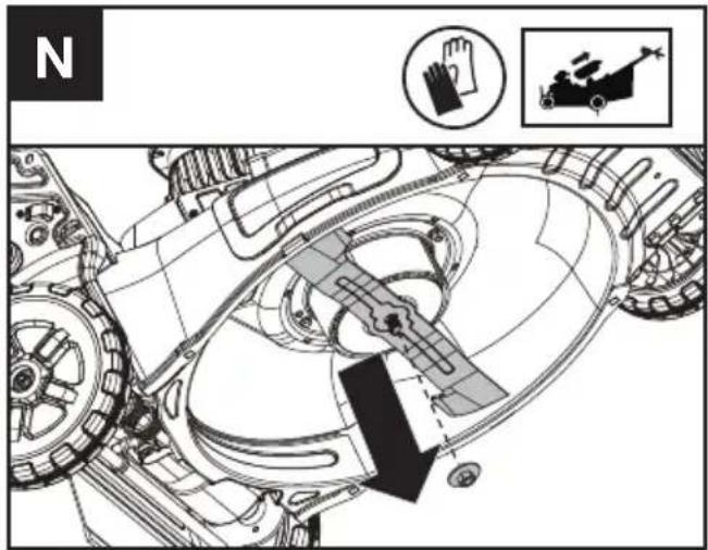
 | Wear protective gloves |
 | Remove battery from the socket before carrying out any adjustment, servicing or maintenance |
 | Batteries may enter water cycle if disposed improperly, which can be hazardous for ecosystem. Do not dispose of waste batteries as unsorted municipal waste. |
 | Do not burn |
 | High speed |
 | Low speed |
 Li-Ion Li-Ion | Li-Ion battery This product has been marked with a symbol relating to ‘separate collection’ for all battery packs and battery pack. It will then be recycled or dismantled in order to reduce the impact on the environment. Battery packs can be hazardous for the environment and for human health since they contain hazardous substances. |
 | Waste electrical products must not be disposed of with household waste. Please recycle where facilities exist. Check with your local authorities or retailer for recycling advice. |
NOTE: Before using the tool, read the instruction book carefully.

BEFORE OPERATION:
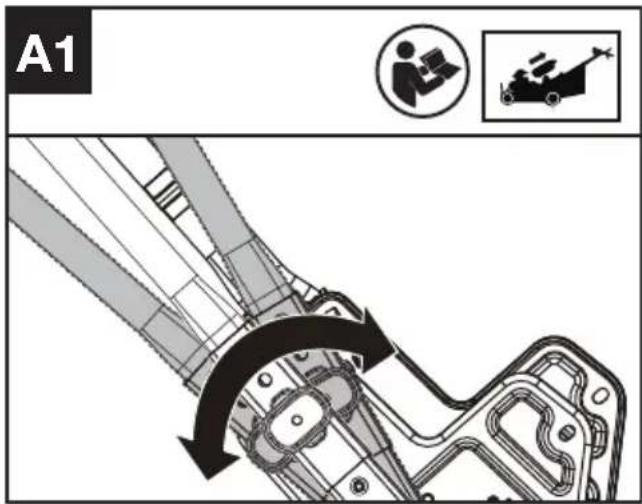
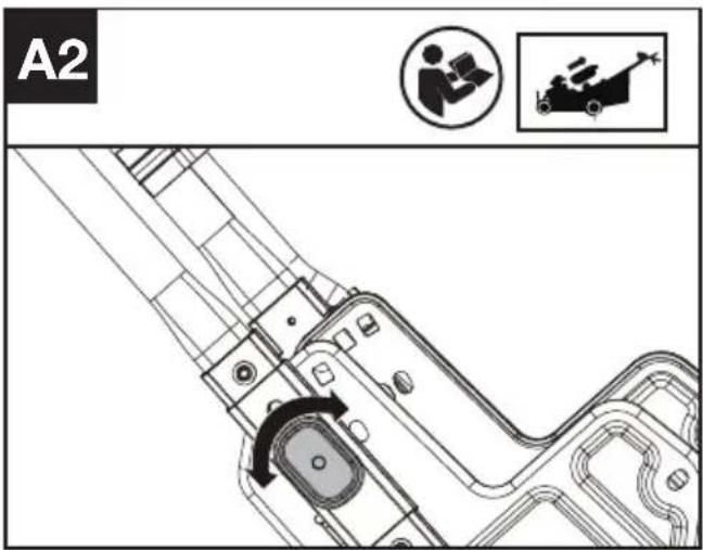
Adjusting handle's height and assembling the lower handles. (See Fig. A1,A2)
3 height levels can be selected. Select the appropriate height and rotate the handle height adjustment knob.
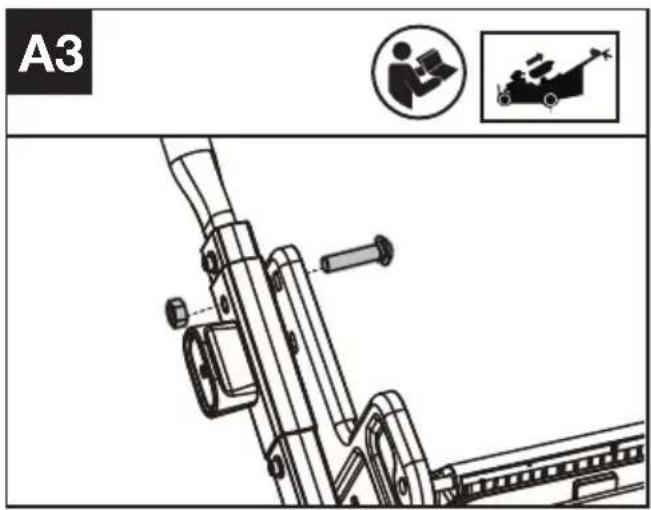
Fastening the lower handle. (Optional fastening if required) (See Fig. A3)
Using the bolt and nut to fasten the lower handle. NOTE: It will be unavailable to fold the handles after fastening the lower handle.
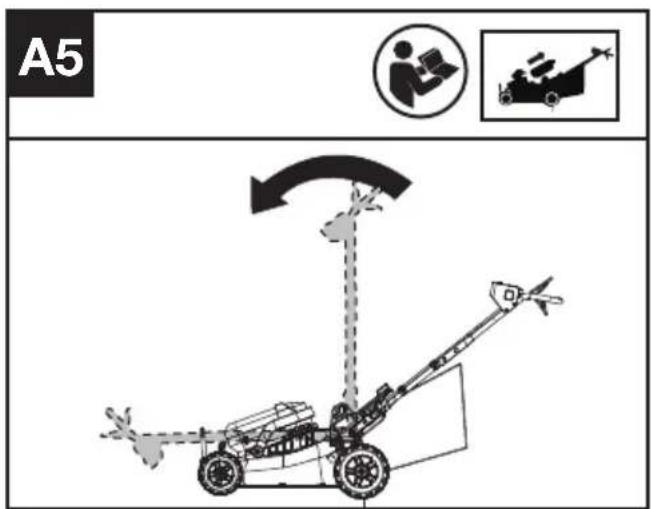
Assembling the upper handle. (See Fig. A4)
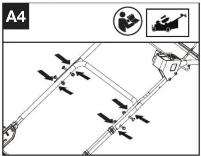
NOTE: The handles can be fold up for transportation or off-season storage. (See Fig. A5) When folding the handles, the folding switch will be triggered, and the mower cannot be turned on at this time. Until the handles are reset, the switch will be automatically turned off, and the mower can start to operate normally.
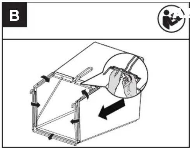
Assembling the grass collection bag (See Fig. B)
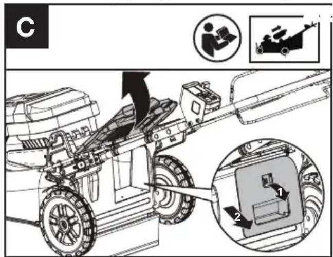
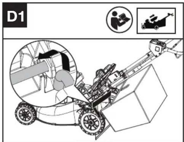
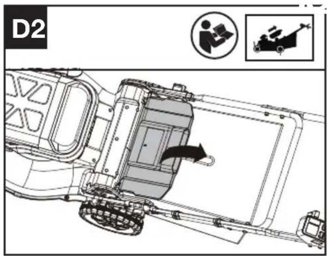
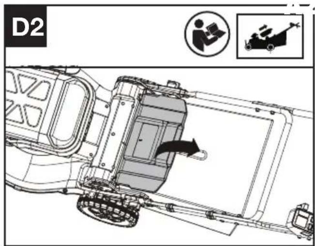
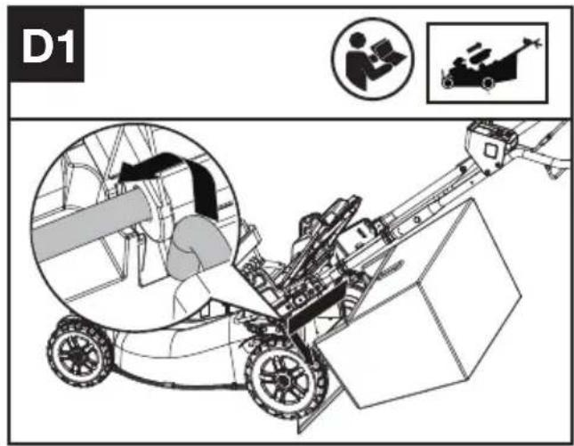
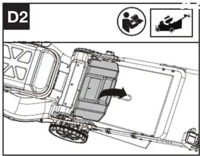
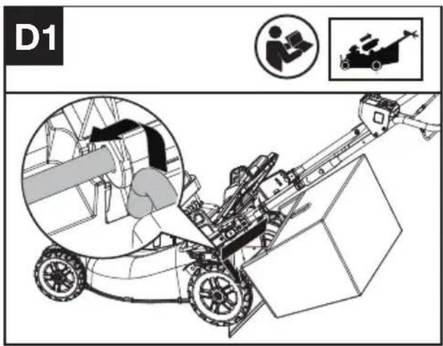
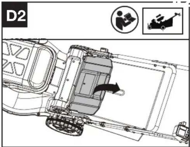
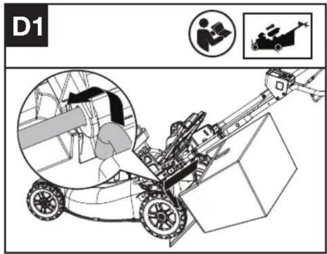
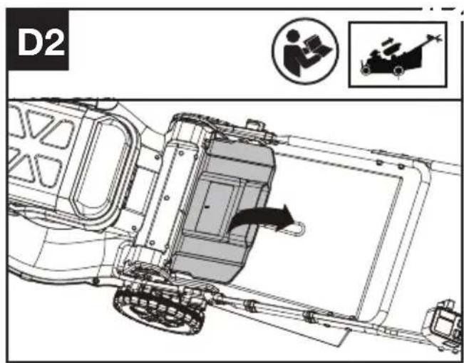
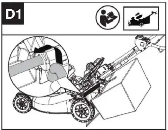
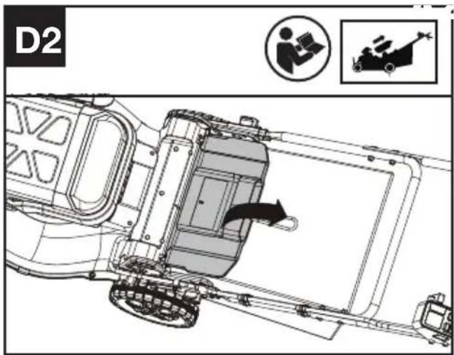
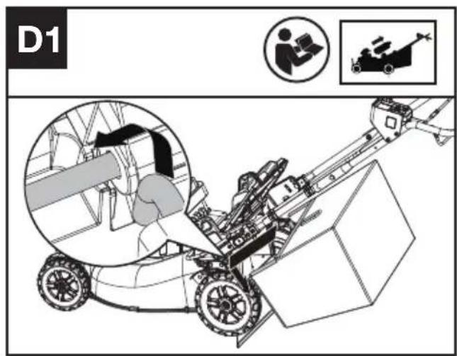
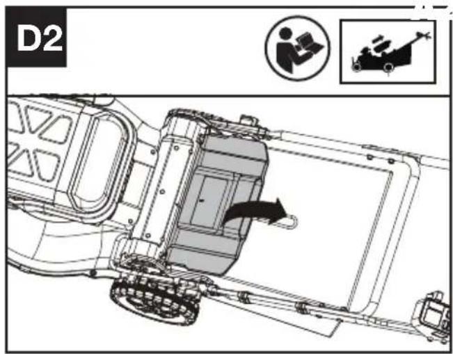
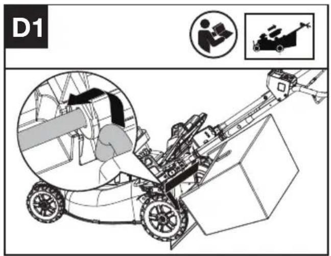
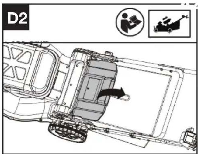
Assembling the grass collection bag to the lawn mower(See Fig. C,D1,D2)
NOTE: Depress the grass collection bag slightly to ensure that it is completely installed.
NOTE: Take the mulching plug out of the lawn mower before fitting the grass collection bag.
Checking the battery charge condition and charging the battery pack.
NOTE: The batteries are shipped uncharged. The battery must be fully charged before the first mow. More details can be found in the manual of battery and charger.
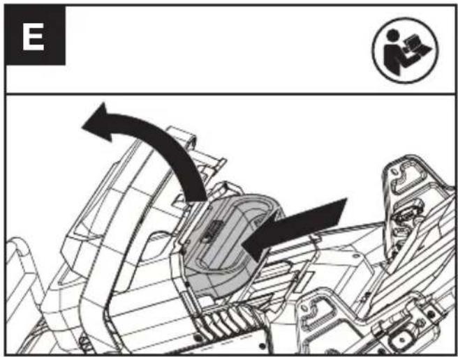
Fitting/removing the battery (See Fig. E)
Checking the controls
- Remove the battery.
- Try to press the on/off switch, cutting blade start button, or cutting speed control. If the on/off switch, cutting blade start button, or cutting speed control gets stuck and cannot spring back to its original position, stop using the mower and contact the service agent.
- Try to pull and release the operating bail or self-propel engagement bail. If the operating bail or self-propel engagement bail gets stuck and cannot spring back to its original position, stop using the mower and contact the service agent.
- Rotate the self-propel speed control. If the self-propel speed control gets stuck, stop using the mower and contact the service agent.
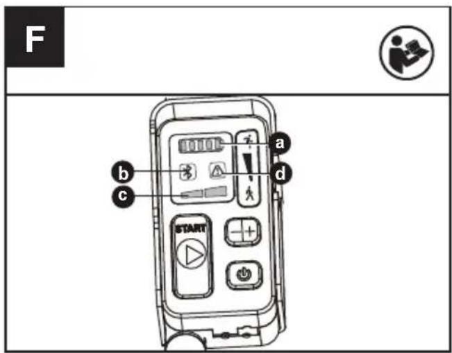
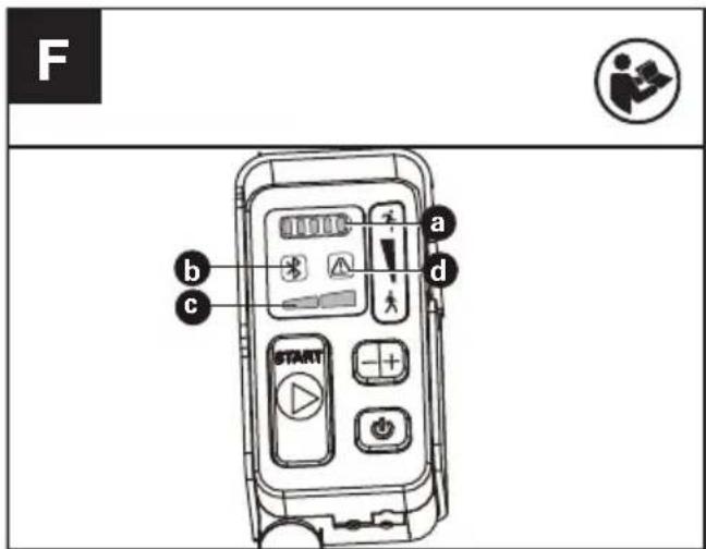
Checking the display (See Fig. F)
-
Fit the battery.
-
Keep pressing the on/off switch and the battery indicator (a) and cutting speed indicator (c) become lit.
- Press the cutting blade start button and pull the operating bail to start the machine.
- If the warning indicator (d) lights up or is flashing, refer to Troubleshooting for solutions.
- Release the operating bail. The blade stops rotating after a short delay. If the mower cannot stop, remove the battery and contact the service agent.
LED indicators
a. BATTERY INDICATOR
b. BLUETOOTH INDICATOR
c. CUTTING SPEED INDICATOR
d. WARNING INDICATOR
Adjusting the cutting height (See Fig. G)
Adjust the cutting height through cutting height adjustment levers of front and rear wheel.
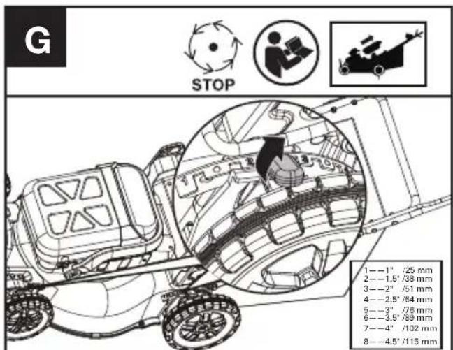
WARNING! Stop, release operating bail and wait until the motor stops before adjusting height. The blades continue to rotate after the machine is switched off, a rotating blade can cause injury. Do not touch rotating blades.
OPERATION:
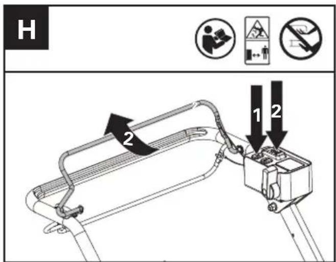
Starting & Stopping the mower (See Fig. H)
- Press the on/off switch
- Press the cutting blade start button (Hold Down) and pull the operating bail to start the machine.
- Release the operating bail to stop.

WARNING! The blade continues to rotate after the mower has been switched off; wait has completely stopped.
NOTE: For starting, press the cutting blade start button and pull the operating bail at the same time. NOTE: Keep pressing the on/off switch and the dispaly become lit. The display will automatically turn off if there is no any operation within 60 seconds.
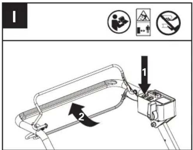
Operating the self-propel system (See Fig. I)
- Press the on/off switch
- Pull the self-propel engagement bail to start the self-propel system.
- Release the self-propel engagement bail to stop.
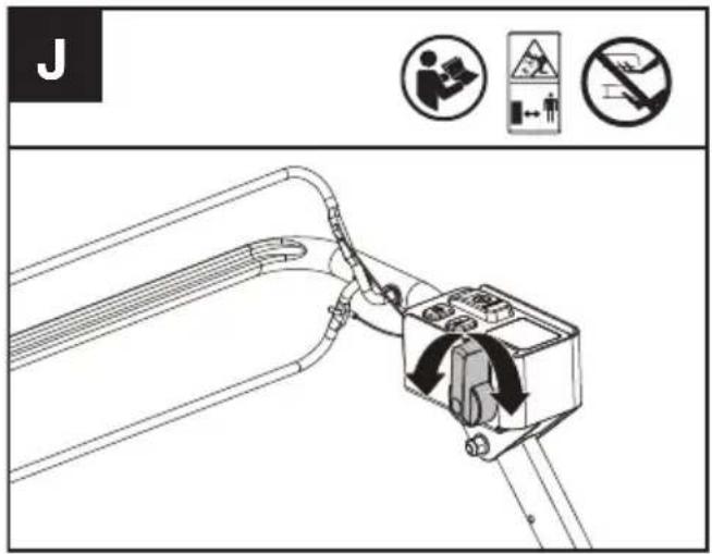
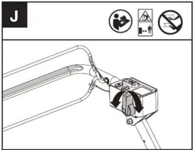
Selecting self-propel speed (See Fig.J)
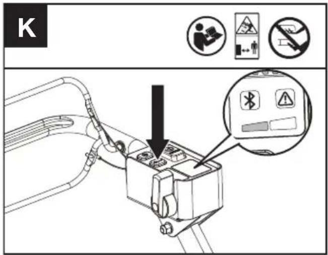
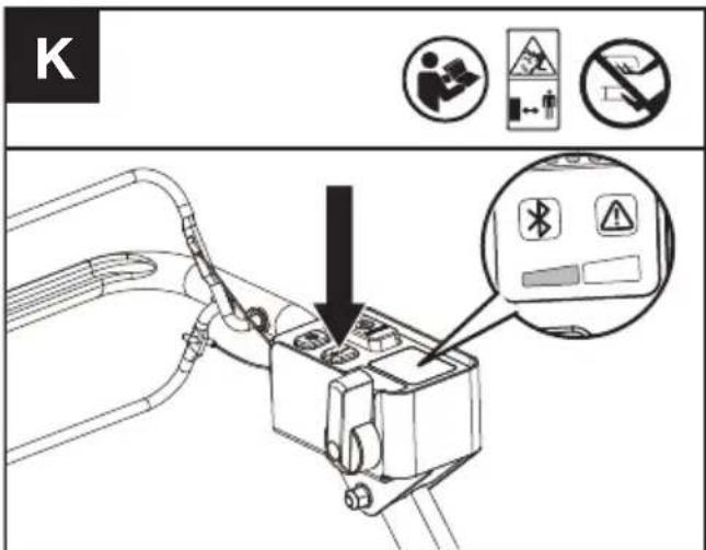
Selecting cutting speed (See Fig. K)
2 cutting speed levels can be selected depending on the application. Use the +/- to control the speed, which is as indicated by the LED indicators. The higher the cutting speed level, the faster the tool runs.
MULCHING MOWING TIPS
While mulching, your new mower is designed to cut the grass clippings into small pieces and distribute them back into the lawn. Under normal conditions, the mulched grass will biodegrade quickly and deliver nutrients to the lawn. Please review the following recommendations for optimum mulching performance.
1) Avoid mowing when the grass is wet from rain or dew. Wet grass may form clumps which interfere with the mulching action and reduce the runtime.
2) For the best mulching performance, set the cutting height to remove about one third of the grass blade length, ideally no more than 40 mm at one time. If the lawn is overgrown, it may be necessary to increase the cutting height to reduce the pushing effort and prevent overloading the motor. For extremely heavy mulching, it is advisable to first cut at a high cut height setting, and then re-cut to the final cut height. Otherwise, make narrower cuts and mow slowly.
3) For the best performance, keep the mower
housing free of built-up grass. From time to time turn off mower and wait for the blades to come to a complete stop. Remove the batteries and turn mower on its side. Using an object such as a stick, wipe out any accumulation of grass around the blade area. Be careful of the sharp edges of the blade. Ensure to clean the blade area often when cutting wet or new grass and every time after the machine is used.
4) Certain types of grass or grass conditions may require that an area be mulched a second time to fully disperse the grass throughout the lawn. If cutting a second time, it is advisable to cut perpendicular (across) the first cut pattern. DO NOT CHANGE CUT PATTERN IN ANY WAY THAT WOULD CAUSE MOWING DOWN A HILL.
5) Change your cutting pattern from week to week. This will help prevent matting and graining of the lawn.
6) Do not mow on a slope that has an angle of greater than 20^
CUTTING AREA
The cutting area can be affected by several factors, such as cutting height, lawn humidity, grass length and density. Besides, starting and stopping the mower too many times during operation will reduce the cutting area.
TIPS:
1) It is recommended to mow your lawn more frequently, walk at normal pace, and not to start/stop the mower too often during operation.
2) For best performance, please ensure battery pack is fully charged and always cut off 1/3 or less of the grass height. It is suggested to install a new blade before the cutting season begins.
3) Walk slowly when cutting long grass, so as to have more effective cutting and properly discharge the clippings.
4) Avoid cutting wet grass, otherwise it will stick to the underside of the deck and the clippings cannot be collected or discharged properly.
5) A higher cutting height shall be applied to new or thick grass and it will extend the battery duration.
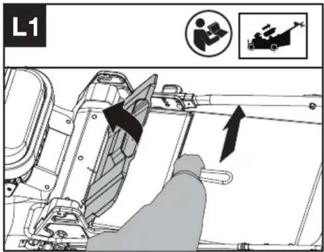
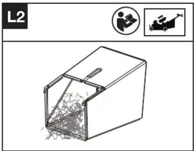
Removing/emptying grass collection bag (See Fig. L1, L2)
WARNING! Always check the safety flap has closed the discharge outlet before using. Never lift the safety flap or remove the mulching plug when the lawn mower is being used without fitted grass collection bag.
FOR BATTERY TOOLS
The recommended ambient temperature range for discharging is -20 °C\~45 °C (-4 °F\~113 °F). The recommended ambient temperature range for the charging system during charging is -5 °C\~45 °C (23 °F\~113 °F).
TRANSPORTATION
Transporting the mower
- Switch off the mower and remove the battery.
- When transporting your mower, the self drive can be used without engaging the cutting blade.
- For lifting the mower, it is recommended that two people lift from each side of the mower using the motor guard and lower handle connection areas as handles.
Transporting the battery
- Ensure the battery is in a safe condition.
- Use non-conductive packaging when transporting the battery.
- The contained Li-Ion batteries are subject to the dangerous goods legislation requirements.
Transport batteries only when the battery housing is undamaged. Pack up the batteries in such a manner that cannot move around in the packaging.
MAINTENANCE

WARNING! Stop the mower and remove the battery before removing the grass collection
bag.
NOTE: To ensure long and reliable service, perform the following maintenance procedures regularly. Check for obvious defects such as a loose, dislodged or a damaged blade, loose fittings, and worn or damaged components. Check that the covers and guards are all undamaged and are correctly attached to mower. Carry out any necessary maintenance or repairs before operating mower. If the mower should happen to fail despite regular maintenance, please call our customer helpline for advice.
BLADE SHARPENING
KEEP BLADE SHARP FOR BEST MOWER PERFORMANCE. A DULL BLADE DOES NOT CUT GRASS CLEANLY OR MULCH PROPERLY. WEAR EYE PROTECTION AND ANTI-CUT GLOVES WHILE REMOVING, SHARPENING, AND INSTALLING BLADE.
NOTE: Sharpening or replacing the blade after every 50 hours. Sand causes the blade to dull quickly. If your lawn has sandy soil, more frequent sharpening or replacing may be required.
REPLACE BENT OR DAMAGED BLADE IMMEDIATELY.
WHEN SHARPENING THE BLADE
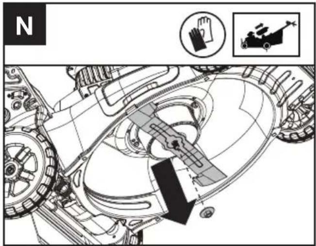
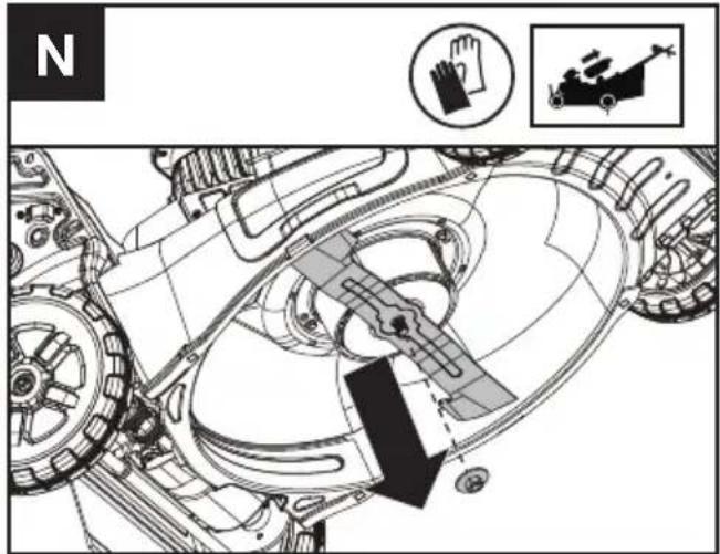
- Use a block of wood placed to prevent the blade from turning.
- Using the socket and wrench, remove the blade bolt and then the blade.(See the blade removing section)
- Clamp the blade in a vice, or similar, to prevent it from moving during sharpening.
- Sharpen the cutting edges on both ends of the blade. Ensure that the same amount of material is removed from both ends to keep the blade balanced.
- Check the blade balance. (See the blade balancing section)
- Replace the blade in the reverse order of the disassembly.
- Make sure to tighten the blade bolt to the required torque (25 Nm).
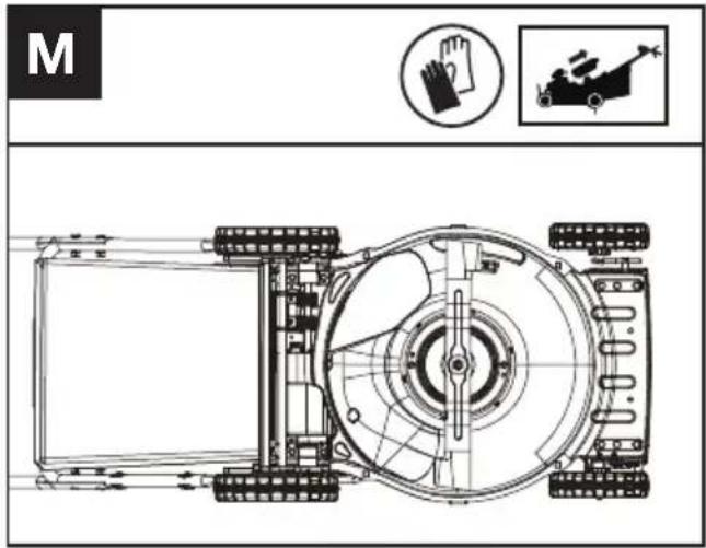
NOTE:
- Be sure the mower is turned off and remove the battery.
- Tip the mower onto its side as shown in figure M
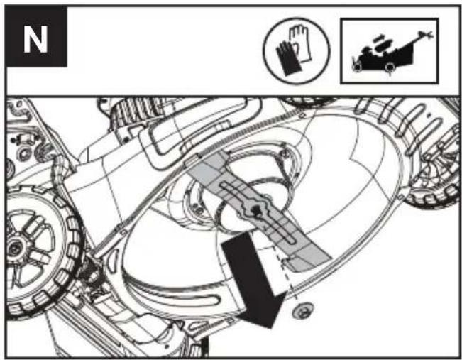
BLADE REMOVING (SEE FIG. N)
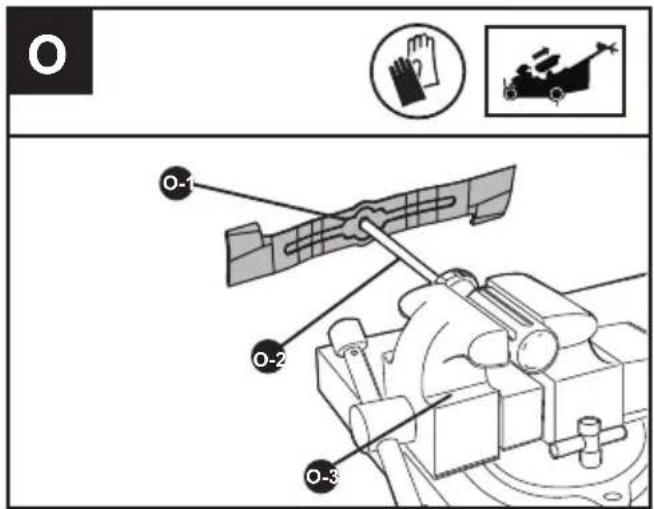
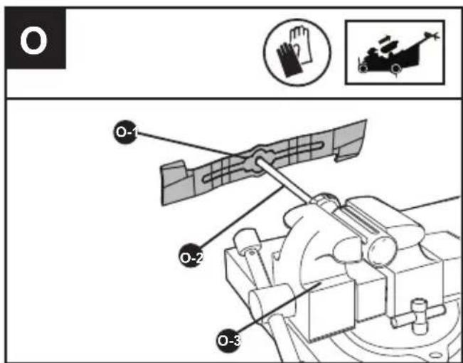
BLADE BALANCING (SEE FIG. O)
Check balance of blade by placing center hole in blade O-1 over a screwdriver shank O-2, clamped horizontally in a vise O-3. If either end of the blade rotates downward, file that end. Blade is properly balanced when neither end drops.
BLADE REPLACING
-Suggest to replace different mower blades according to different working conditions for
better using experience.
| BLADE | FUNCTION |
| Low lift blade | For extended run time |
| Medium-lift blade Multi-purpose | |
| High-lift blade | Recommended for bagging |
| Gator blade | Recommended for mulching |
CLEANING
- Stop the mower and remove the battery.
- Do not use aggressive detergents or solvents. Clean the machine after use with a damp cloth dipped in mild detergent.
- Keep battery connection free of dirt and debris, and clean with a soft and dry brush or cloth.
- Do not spray water onto the motor and electrical components.
- Do not use pressure washer to clean your machine.
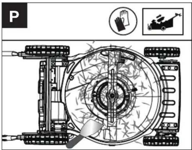
Cleaning the deck and the blade area. (See Fig. P)
Cleaning grass clippings and debris off of the deck and the balde area.
If grass cuttings are compacted in the blade area, remove with a wooden or plastic implement.
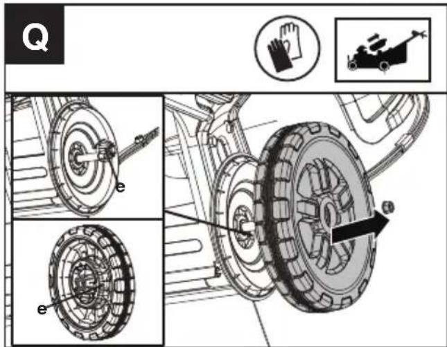
Cleanig the wheels. (See Fig. Q)
- Stop the mower and remove the battery.
- Cleaning the wheels every 50 hours or more frequently in extreme conditions.
- Remove the rear wheels and clean the grass clippings and debris from the wheel-gear area.
- It is suggested to apply a small amount of anti-seize compound to the gears(e) after cleaning.
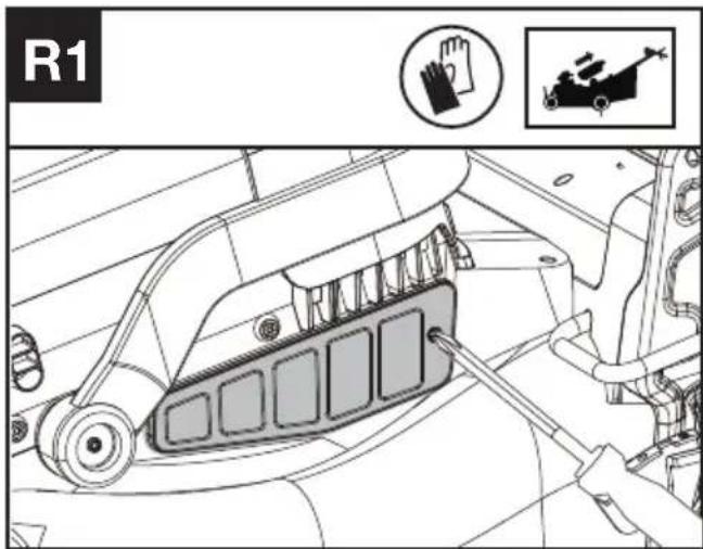
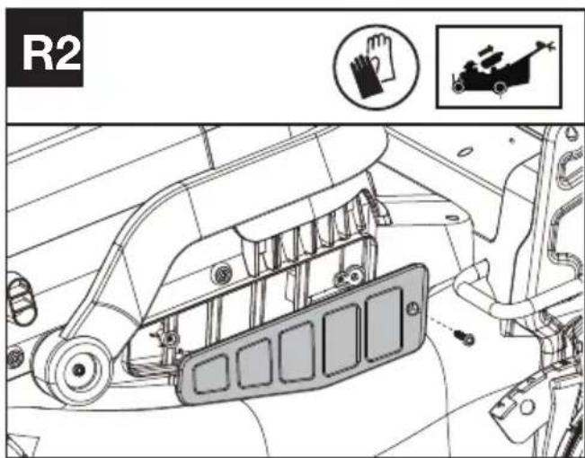
Cleaning the air filter (See Fig. R1, R2)
- Clean the area around the air filter. Use a damp cloth or a soft brush.
- Unscrew and remove the air filter.
- Wash the air filter with running water to remove the dirt.
- Allow the air filter to dry in the air. And then install it in the housing by thightening the screw.
STORAGE
- Stop the mower and remove the battery.
- Clean the exterior of the machine thoroughly using a soft brush and cloth. Do not use solvents or polishes. Remove all grass and debris, especially from the ventilation slots, mulching plate, blade area and the wheels.
- Store the machine in a dry place, where is out of the reach of children and other unauthorized people. Do not place other objects on top of the machine.
- To aid storage, fold the handle bar.
- Store the battery only within a temperature range between 5^ C ( 41^ F) and 25^ C ( 77^ F). As an example, do not leave the battery in the car in summer time.
- Once got wet in the rain during operation, the machine and the battery should be dried before storing or charging. Remove the battery and reinsert it if the machine fails to turn on.
TROUBLESHOOTING
The following table gives problems and actions that you can perform if your machine does not operate correctly.
WARNING: Switch the machine off and remove the battery prior to any troubleshooting.
| PROBLEM SOLUTION | |
| 1. Mower doesn't run when operating bail is activated. | A. Check to make sure that cutting blade start button is being completely pressed.B. Release operating bail to turn mower off. Remove the battery, turn mower over and check that blade is free to turn.If not free, return to an authorized servicer. Blade should turn freely.C. Has battery been fully charged? Plug in charger and wait for green light to come on.D. For starting, press both the cutting blade start button and pull the operating bail at the same time. |
| 2. Motor stops while mowing. A. Release | operating bail to turn mower off. Remove the battery,turn mower over to check if mower is plugged with grass debris,remove debris from blade rotation area. Then, check that blade is free to turn. If not free, return to an authorized servicer. Blade should turn freely.B. Raise cutting height of wheels to highest position and startmower.C. Has battery been fully charged? Plug in charger and wait for green light to come on.D. Avoid overloading the mower. Slow down the cutting pace by pushing mower slower or raise the cut height. Or both. |
| 3. Mower runs but cutting performance is unsatisfactory, or does not cut entire lawn. | A. Has battery been fully charged? Plug in charger and wait for green light to come on.B. Release operating bail to turn mower off. Remove the battery. Turnmower over and check: Blade for sharpness - Keep blade sharp.Deck and discharge chute for clogging.C. Wheel height adjustment may be set too low for grass condition.Raise cutting height. |
| 4. Mower is too hard to push. A. Raise cutting height to reduce deck drag on grass. Check each wheel for free rotation. | |
| 5. Mower is abnormally noisy and vibrates. | A. Release operating bail to turn mower off. Remove the battery. Turn mower on side and check blade to ensure it has not been bent or damaged. If blade is damaged, replace with a replacement blade. If the underside of the deck is damaged return mower to an authorized service center.B. If there is no visible damage to the blade and the mower still vibrates: Release operating bail to turn mower off, remove the battery, and remove the blade. Rotate blade 180 degrees and retighten. If mower still vibrates, return the mower to an authorized service center. |
| 6. Battery charger LED's not on. A. Check plug connection.B. Replace charger. | |
| 7. Battery charger LED does not flip to green. | A. Battery needs to be diagnosed. Take to authorized service center. |
| 8. Mower not picking up clippings with the grass collection bag. | A. Rear chute clogged. Release operating bail to turn mower off. Remove the battery. Clear chute of grass clippings.B. Too much cut grass. Raise cutting height of wheels to shorten length of the cut.C. Bag full. Empty bag more often. |
| 9. When mulching there are clippings visible. | A. Too much cut grass. Raise cutting height of wheels to shorten length of the cut. Do not cut off more than 1/3 of total length.B. Check blade for sharpness. Always keep blade sharp.C. Reduce speed if grass is high or extremely thick. |
| 10. Low or diminished run-time after many uses | A. Return to authorized service location - may need new battery. |
| 11. Warning indicator lights up or is flashing | A. Overload-The cutting blade is jammed. Deactivate the product. Remove the battery. Clean the blade area and remove unwanted materials.B. Temperature issue-Let the product cool down.C. Other problems-Contact service agent |
TECHNICAL DATA
Type Designation: KC711 KC711.X (711-designation of machinery, representative of Reinforced Steel Deck SP Mower)
| KC711 KC711.X ** | |
| Voltage 60V Max*** | --- |
| Deck material | Reinforced steel -1.8 mm |
| Cutting width | 51 cm |
| Max. SP Speed | 6.4 km/h |
| Cutting height | 25-115 mm |
| Cutting height positions | 8 |
| Grass collection capacity | 88 L |
| Degree of protection IPX4 | |
| Run time 70min@11Ah**** |
Machine weight (bare tool) 42 kg
** X=1-999,A-Z,M1-M9 they are only used for different customers, there are no safe relevant changes between these models.
*** Voltage measured without workload. Initial battery voltage reaches maximum of 60 volts. Nominal voltage is 54 volts.
**** Run time may vary depending on how the tool is used and grass conditions. The selected cutting speed level affects the battery's runtime. The lower the cutting speed level, the longer the run time.
SUGGESTED BATTERIES AND CHARGERS
| Battery Capacity Charger Amperage | |||
| KAC804 4 Ah | KAC840 30 A | ||
| KAC810 11 Ah |
We recommend that you purchase your accessories from the same Dealer that sold you the tool. Refer to the accessory packaging for further details. Your Dealer can assist you and offer advice.
TECHNICAL DATA FOR BATTERY PACK (OPTIONAL)
| Frequency bands for Bluetooth 2400-2483.5 MHz | |
| Maximum Output Power for Bluetooth | 8 dBm |
EN
NOISE INFORMATION
| A weighted sound pressure L | _pA = 80.7 dB(A) |
| K_pA | 3 dB(A) |
| A weighted sound power L | _wA = 95.3 dB(A) |
| K_wA | 1.1 dB(A) |
| Wear ear protection |
VIBRATION INFORMATION
Typical weighted vibration a
_h<2.5 m/s^2
Uncertainty K = 1.5 m/s^2
WARNING: The vibration emission value during actual use of the power tool can differ from the declared value depending on the ways in which the tool is used dependant on the following examples and other variations on how the tool is used:
How the tool is used and the materials being cut or drilled.
The tool being in good condition and well maintained
Using the correct accessory for the tool and ensuring it is sharp and in good condition.
The tightness of the grip on the handles and if any anti vibration accessories are used.
And the tool is being used as intended by its design and these instructions.
This tool may cause hand-arm vibration syndrome if its use is not adequately managed.
WARNING: To be accurate, an estimation of exposure level in the actual conditions of use should also take account of all parts of the operating cycle such as the times when the tool is switched off and when it is running idle but not actually doing the job. This may significantly reduce the exposure level over the total working
period.
Helping to minimise your vibration exposure risk.
ALWAYS use sharp chisels, drills and blades
Maintain this tool in accordance with these instructions and keep well lubricated (where appropriate)
If the tool is to be used regularly then invest in anti vibration accessories.
Plan your work schedule to spread any high vibration tool use across a number of days.
ENVIRONMENTAL PROTECTION

Waste electrical products must not be
disposed of with household waste. Please
recycle where facilities exist. Check with your
local authorities or retailer for recycling advice.
DECLARATION OF CONFORMITY
We,
Positec Germany GmbH
Postfach 32 02 16, 50796 Cologne, Germany
On behalf of Positec declare that the product
Description Battery powered Lawn Mower
Type KC711 KC711.X (711-designation of
machinery, representative of Reinforced Steel Deck SP Mower)
Function cutting grass
Complies with the following Directives:
2006/42/EC, 2014/30/EU, 2011/65/EU & (EU)
2015/863, 2000/14/EC amended by 2005/88/EC
2000/14/EC amended by 2005/88/EC:
- Conformity Assessment Procedure as per
- Measured Sound Power Level
- Declared Guaranteed Sound Power Level
Annex VI
95.3 dB (A)
96 dB (A)
The notified body involved
Name: TÜV Rheinland LGA Products GmbH (
Notified body 0197)
Address: Tillystraße 2-90431 Nürnberg
Standards conform to
EN 62841-1, EN IEC 62841-4-3, EN ISO 3744, EN
IEC 55014-1, EN IEC 55014-2
The person authorized to compile the technical file,
Name Marcel Filz
Address Positec Germany GmbH
Postfach 32 02 16, 50796 Cologne, Germany


2022/08/29
Allen Ding
Deputy Chief Engineer, Testing & Certification
Positec Technology (China) Co., Ltd
18, Dongwang Road, Suzhou Industrial
Park, Jiangsu 215123, P. R. China
DECLARATION OF CONFORMITY
We,
Positec (UK & Ireland) Ltd
PO Box 6242, Newbury, RG14 9LT, UK
On behalf of Positec declare that the product
Description Battery powered Lawn Mower
Type KC711 KC711.X (711-designation of machinery, representative of Reinforced Steel Deck SP Mower)
Function cutting grass
Complies with the following Directives:
Supply of Machinery (Safety) Regulations 2008
Electromagnetic Compatibility Regulations 2016
The Restriction of the Use of Certain Hazardous
Substances in Electrical and Electronic Equipment Regulations
Noise Emission in the Environment by Equipment for Use Outdoors Regulations
- Conformity Assessment Procedure as per SCHEDULE 9
- Measured Sound Power Level 95.3 dB (A)
- Declared Guaranteed Sound Power Level 96 dB (A)
The notified body involved
Name: TÜV Rheinland LGA Products GmbH (
Notified body 0197)
Address: Tillystraße 2-90431 Nürnberg
Standards conform to
BS EN 62841-1, BS EN 62841-4-3, BS EN ISO
3744, BS EN IEC 55014-1, BS EN IEC 55014-2
The person authorized to compile the technical file,
Name Jim Kirkwood
Address Positec (UK & Ireland) Ltd,
PO Box 6242, Newbury, RG14 9LT, UK


2022/08/29
Allen Ding
Deputy Chief Engineer, Testing & Certification
Positec Technology (China) Co., Ltd
18, Dongwang Road, Suzhou Industrial
Park, Jiangsu 215123, P. R. China
INHALTSVERZEICHNIS
Einführung......21
Komponenten....23
KOMPONENTEN
ERSETZEN DES MÄHMESSERS
- Measured Sound Power Level 95.3 dB
(A)
18, Dongwang Road, Suzhou Industrial
Park, Jiangsu 215123, P. R. China
SOMMAIRE
Introduction......40
LISTE DES COMPOSANTS
-
COMMANDE D'ENTRAÎNEMENT (ENGAGEMENT DE LAME)
-
COMMANDE D'ACTIVATION DU SYSTÈME AUTO-TRACTÉ
-
POIGNÉE SUPÉRIEURE
-
POIGNÉE INFÉRIEURE
-
FIXATIONS DE POIGNÉE
-
SERRE-CÂBLE
-
SAC DE COLLECTE D'HERBE
-
INTERRUPTEUR DE RABATTEMENT
-
VOLET DE SÉCURITÉ
-
BOUTON DE RÉGLAGE DE LA HAUTEUR
-
ROUE ARRIÈRE
-
FILTRE À AIR
-
COUVERCLE DU COMPARTIMENT DE LA BATTERIE
-
ROUE AVANT
-
PROTECTION DE MOTEUR
-
LAME
-
ENTRETOISE
-
BOULON DE LAME
-
BLOC DE BATTERIE*
-
LEVIER DE RÉGLAGE DE LA HAUTEUR DE COUPE AVANT
-
LEVIER DE RÉGLAGE DE LA HAUTEUR DE COUPE ARRIÈRE
-
VOLET EN CAOUTCHOUC
-
FICHE DE PAILLAGE
-
COMMANDE DE VITESSE AUTO-TRACTÉE
-
INDICATEURS LED
-
BOUTON DE DÉMARRAGE DE LA LAME DE COUPE
-
COMMANDE DE VITESSE DE COUPE
-
INTERRUPTEUR MARCHE/ARRÊT
REPLACEMENT DE LA LAME
INFORMATIONS RELATIVES AU BRUIT
INFORMATIONS RELATIVES AUX VIBRATIONS
18, Dongwang Road, Suzhou Industrial
Park, Jiangsu 215123, P. R. China
INDICE
Introduzione....59
ELEMENTI DELL'APPARECCHIO
natural_image
Top-down technical diagram of a vehicle chassis with labeled components and hand symbols (no readable text or labels)18, Dongwang Road, Suzhou Industrial
Park, Jiangsu 215123, P. R. China
ÍNDICE
Introducción....77
Lista de componentes....79

CAMBIO DE CUCHILLA
18, Dongwang Road, Suzhou Industrial
Park, Jiangsu 215123, P. R. China
ÍNDICE
Introdução....95
Lista de componentes....97
REMOÇÃO DA LÂMINA (VER A FIG. N)
CALIBRAR A LÂMINA (VEJA FIGURA O)
Limpar o filtro de ar (Ver a Fig. R1, R2)
18, Dongwang Road, Suzhou Industrial
Park, Jiangsu 215123, P. R. China
INHOUDSOPGAVE
Inleiding....113
DRIE SNELHEIDSINSTELLINGEN
-
BEDIENINGSBEUGEL (INSCHAKELING VAN HET MES)
-
BEUGEL VOOR ZELFAANDRIJVING
-
BOVENSTE HANDGREEP
-
ONDERSTE HANDGREEP
-
HANDGREEPBEVESTIGINGEN
-
KABELKLEM
-
GRASOPVANGZAK
-
KLAPSCHAKELAAR
-
VEILIGHEIDSFLAP
-
HOOGTE-INSTELKNOP
-
ACHTERWIEL
-
LUCHTFILTER
-
DEKSEL VAN ACCUVAK
-
VOORWIEL
-
MOTORBEVEILIGING
-
MES
-
AFSTANDHOUDER
-
MESBOUT
-
ACCUPAKKET*
-
VOORSTE HENDEL VOOR MAAIHOOGTE-INSTELLING
-
ACHTERSTE HENDEL VOOR MAAIHOOGTE-INSTELLING
-
RUBBEREN FLAP
-
MULCHING-PLUG
-
SNELHEIDSREGELING VOOR ZELFAANDRIJVING
-
LED-INDICATOREN
-
STARTKNOP VOOR MAAIMES
-
MAAISNELHEIDSREGELING
-
AAN/UIT-SCHAKELAAR
OORSPRONKELIJKE GEBRUIKSAANWIJZING PRODUCTVEILIGHEID ALGEMENE VEILIGHEIDSWAARSCHUWINGEN VOOR VERMOGENS MACHINE

WAARSCHUWING: Lees alle veiligheidswaarschuwingen,
- Remove the battery.
- Try to press the On/Off Switch, Cutting Blade
Start Button, or Cutting Speed Control Button. If the On/Off Switch, Cutting Blade Start Button, or Cutting Speed Control Button gets stuck and cannot spring back to its original position, stop using the mower and contact the service agent.
- Try to pull and release the Operating Bail or Self-Propelled Engagement Bail. If the Operating Bail or Self-Propelled Engagement Bail gets stuck and cannot spring back to its original position, stop using the mower and contact the service agent.
- Rotate the Self-Propel Speed-Control. If the Self-Propel Speed-Control gets stuck, stop using the mower and contact the service agent.
c. INDICATOR VOOR MAAISNELHEID
d. WAARSCHUWINGSINDICATOR
TIPS VOOR MAAIEN MET GRASBEMESTING
natural_image
Top-down technical diagram of a vehicle chassis with visible components and directional indicators (no text or labels)MES VERVANGEN
WAARSCHUWING: Voor de
18, Dongwang Road, Suzhou Industrial
Park, Jiangsu 215123, P. R. China
TARTALOMJEGYZÉK
Bevezető....131
VÁGÓKÉS CSERÉJE
18, Dongwang Road, Suzhou Industrial
Park, Jiangsu 215123, P. R. China
CUPRINS
Introducere....149
LISTA DE COMPONENTE
| 1. | BARA DE FUNCTIONARE (ACTIONARE A LAMEI) |
| 2. | BARA DE ACTIONARE A AUTOPROPULSÄRII |
| 3. | MÄNER SUPERIOR |
| 4. | MÄNER INFERIOR |
| 5. | ŞURUBURI DE STRÂNGERE A MÄNERULUI |
| 6. | CLEMÄ CABLU |
| 7. | SAC COLECTARE IARBÄ |
| 8. | BUTON DE PLIERE |
| 9. | CLAPETÄ DE SIGURANTÄ |
| 10. | BUTON DE AJUSTARE A ÎNÄLTIMII |
| 11. | ROATÄ SPATE |
| 12. | FILTRU DE AER |
| 13. | CAPACUL COMPARTIMENTULUI DE ACUMULATOR |
| 14. | ROATÄ FATÄ |
| 15. | PROTECTIE MOTOR |
| 16. | LAMÄ |
| 17. | DISTANTIER |
| 18. | BOLT LAMÄ |
| 19. | ACUMULATOR* |
| 20. | PÄRGHIE FRONTALÄ DE REGLARE A ÎNÄLTIMII DE TÄIERE |
| 21. | PÄRGHIE SPATE DE REGLARE A ÎNÄLTIMII DE TÄIERE |
| 22. | ŞORT DE CAUCIUC |
| 23. | SERTAR PENTRU RESTURI VEGETALE |
| 24. | BUTON DE CONTROL VITEZÄ DE AUTOPROPULSARE |
| 25. | INDICATORI CU LED |
| 26. | BUTON DE PORNIRE A LAMEI DE TÄIERE |
| 27. | CONTROL VITEZÄ DE TÄIERE |
| 28. | COMUTATOR DE PORNIRE/OPRIRE |
Selectarea vitezei de autopropulsare (A se vedea Fig. J)
Selectarea vitezei de tăiere (A se vedea Fig. K)
natural_image
Top-down technical diagram of a vehicle chassis with labeled components and hand gesture indicators (no text or symbols beyond basic labels)SCOATEREA LAMEI (A SE VEDEA FIG. N)
ECHILIBRAREA LAMEI (CONSULTATI FIG. O)
ÎNLOCUIREA LAMEI
18, Dongwang Road, Suzhou Industrial
Park, Jiangsu 215123, P. R. China
SPIS TREŚCI
Wprowadzenie....168
LISTA KOMPONENTÓW
-
KABŁĄK OPERACYJNY (WŁĄCZANIE OSTRZY)
-
KABŁAK WŁĄCZANIA NAPEĐU
-
UCHWYT GÓRNY
-
UCHWYT DOLNY
-
MOCOWANIA UCHWYTU
-
ZACISK KABLOWY
-
KOSZ NA ŚCIĘTĄ TRAWE
-
PRZEŁĄCZNIK SKŁADANIA
-
KLAPA BEZPIECZEŃSTWA
-
POKRETŁO REGULACJI WYSOKOŚCI
-
KOŁO TYLNE
-
FILTR POWIETRZA
-
POKRYWA KOMORY BATERII
-
PRZEDNIE KOŁO
-
OSŁONA SILNIKA
-
OSTRZE
-
PRZEKŁADKA
-
ŚRUBA BRZESZCZOTA
-
BATERIA AKUMULATOROWA*
-
PRZEDNIA DŻWIGNIA REGULACJI WYSOKOŚCI KOSZENIA
-
TYLNA DźWIGNIA REGULACJI WYSOKOŚCI KOSZENIA
-
GUMOWA KLAPKA
-
ZATYCZKA DO MULCZOWANIA
-
REGULACJA PRĘDKOŚCI NAPEĐU SAMOBIEŻNEGO
-
KONTROLKI LED
-
PRZYCISK URUCHAMIANIA NOŻA
-
REGULACJA PREDKOŚCI KOSZENIA
-
WYŁĄCZNIK
3) For the best performance, keep the mower housing free of built-up grass. From time to time turn off mower and wait for the blades to come to a complete stop. Remove the batteries and turn mower on its side. Using an object such as a stick, wipe out any accumulation of grass around the blade area. Be careful of the sharp edges of the blade. Ensure to clean the blade area often when cutting wet or new grass and every time after the machine is used.
natural_image
Top-down technical diagram of a vehicle chassis with visible components and hand symbols (no text or labels)WYMIANA NOŻA
18, Dongwang Road, Suzhou Industrial
Park, Jiangsu 215123, P. R. China
OBSAH
Úvod....186
SEZNAM KOMPONENT
-
OVLÁDACÍ MADLO (AKTIVACE ČEPELE)
-
POJEZDOVÉ MADLO
-
HORNÍ RUKOJEŤ
-
DOLNÍ RUKOJEŤ
-
UPEVNĚNÍ RUKOJETÍ
-
KABELOVÁ SPONA
-
SBĚRNÝ VAK NA TRÁVU
-
SKLÁDACÍ SPÍNAČ
-
BEZPEČNOSTNÍ KLAPKA
-
KNOFLÍK PRO NASTAVENÍ VÝŠKY
-
ZADNÍ KOLO
-
VZDUCHOVÝ FILTR
-
KRYT PŘIHRÁDKY NA BATERII
-
PŘEDNÍ KOLO
-
KRYT MOTORU
-
ČEPEL
-
PODLOŽKA
-
MATICE ČEPELE
-
BATERIE*
-
PŘEDNÍ NASTAVENÍ VÝŠKY SEKÁNÍ
-
ZADNÍ NASTAVENÍ VÝŠKY SEKÁNÍ
-
GUMOVÁ KLAPKA
-
MULČOVACÍ ZÁTKA
-
OVLÁDÁNÍ RYCHLOSTI POJEZDU
-
LED KONTROLKY
-
STARTOVACÍ TLAČÍTKO SEKÁNÍ
-
OVLÁDÁNÍ RYCHLOSTI SEKÁNÍ
-
VYPÍNAČ
PŮVODNÍ NÁVOD K POUŽÍVÁNÍ BEZPEČNOST VÝROBKU OBECNÁ BEZPEČNOSTNÍ UPOZORNĚNÍ PRO ELEKTRICKÉ NÁSTROJE

VÝMĚNA ČEPELE
INFORMACE TÝKAJÍCÍ SE HLUČNOSTI
18, Dongwang Road, Suzhou Industrial
Park, Jiangsu 215123, P. R. China
OBSAH
Úvod....204
ZOZNAM SÚČASTÍ
-
OVLÁDACIA OBLÚKOVÁ RUKOVÄT (ZÁBER NOŽA KOSAČKY)
-
ZASÚVACIA OBLÚKOVÁ RUKOVÄT SAMOHYBNÉHO SYSTÉMU
-
HORNÁ RUKOVÄT
-
DOLNÁ RUKOVÄT
-
SPOJOVACIE PRVKY RUKOVÄTE
-
KÁBLOVÁ SVORKA
-
VAK NA ZBER TRÁVY
-
SKLÁPACÍ SPÍNAČ
-
BEZPEČNOSTNÁ KLAPKA
-
OTOČNÝ GOMBÍK NA NASTAVENIE VÝŠKY
-
ZADNÉ KOLESO
-
VZDUCHOVÝ FILTER
-
KRYT PRIEHRADKY NA BATÉRIU
-
PREDNÉ KOLESO
-
OCHRANNÝ KRYT MOTORA
-
NÔŽ
-
VYMEDZOVACIA VLOŽKA
-
SKRUTKA NA UPEVNENIE NOŽA
-
BATÉRIOVÝ BLOK*
-
PREDNÁ PÁČKA NA NASTAVENIE VÝŠKY KOSENIA
-
ZADNÁ PÁČKA NA NASTAVENIE VÝŠKY KOSENIA
-
GUMENÁ KLAPKA
-
MULČOVACIA ZÁTKA
-
OVLÁDANIE RÝCHLOSTI SAMOHYBNÉHO SYSTÉMU
-
SVETELNÉ LED KONTROLKY
-
TLAČIDLO SPUSTENIA NOŽA KOSAČKY
-
OVLÁDANIE OTÁČOK KOSENIA
-
VYPÍNAČ
PÔVODNÝ NÁVOD NA POUŽITIE BEZPEČNOST VÝROBKU VŠEOBECNÉ BEZPEČNOSTNÉ UPOZORNENIA

VÝMENA NOŽA KOSAČKY
16, 50796 Cologne, Germany


2022/08/29
Allen Ding
18, Dongwang Road, Suzhou Industrial
Park, Jiangsu 215123, P. R. China
KAZALO VSEBINE
Uvod....222
Sestavni deli....224
Varnost izdelka.... 225
Sestavljanje in način uporabe....228
Prevoz....233
Vzdrževanje....233
Čiščenje....234
Shranjevanje....235
SESTAVNI DELI
-
ROČAJ ZA UPRAVLJANJE (VKLOP REZILA)
-
ROČAJ ZA VKLOP SAMOHODNEGA POGONA
-
ZGORNJI ROČAJ
-
SPODNJI ROČAJ
-
PRITRDILNI ELEMENTI ROČAJA
-
KABELSKA SPONKA
-
KOŠ ZA ZBIRANJE TRAVE
-
STIKALO ZA ZLAGANJE
-
VARNOSTNA LOPUTA
-
GUMB ZA NASTAVITEV VIŠINE
-
ZADNJE KOLO
-
ZRAČNI FILTER
-
POKROV PROSTORA ZA BATERIJE
-
SPREDNJE KOLO
-
ZAŠČITA MOTORJA
-
REZILO
-
DISTANČNIK
-
VIJAK REZILA
-
BATERIJSKI SKLOP
-
SPREDNJA ROČICA ZA NASTAVITEV VIŠINE REZA
-
ZADNJA ROČICA ZA NASTAVITEV VIŠINE REZA
-
GUMIJASTA LOPUTA
-
ZATIČ ZA MULČENJE
-
REGULATOR HITROSTI SAMOHODNEGA POGONA
-
LED INDIKATORJI
-
GUMB ZA ZAGON REZILA
-
REGULATOR HITROSTI REZANJA
-
STIKALO ZA VKLOP/IZKLOP
ZAMENJAVA REZILA
- PREDLAGAJTE ZAMENJAVO RAZLIČNIH REZIL KOSILNICE GLEDE NA RAZLIČNE DELOVNE POGOJE ZA BOLJŠO UPORABO.
18, Dongwang Road, Suzhou Industrial
Park, Jiangsu 215123, P. R. China
SADRŽAJ
Uvod....240
Popis componenti....242
Sigurnost proizvoda....243
Skupina i operacija....246
Transport....250
Održavanje....251
Čišćenje....252
Skladištenje....253
Otklanjanje poteškoća....254
Tehnički podaci....255
HR
Zaštita okoliša....256
Izjava o sukladnosti....257
UVOD
Poštovani,
POPIS KOMPONENTI
-
RADNI MEHANIZAM (AKTIVACIJA OŠTRICE)
-
SAMOHODNI MEHANIZAM
-
GORNJA RUČKA
-
DONJA RUČKA
-
PRIČVRŠČIVAČI RUČKE
-
OBUJMICA ZA KABEL
-
KOŠARA SA SAKUPLJANJE TRAVE
-
PREKIDAČ ZA PREKLAPANJE
-
SIGURNOSNI ZAKLOPAC
-
GUMB ZA PODEŠAVANJE VISINE
-
STRAŽNJI KOTAČ
-
FILTAR ZRAKA
-
POKLOPAC PRETINCA ZA BATERIJU
-
PREDNJI KOTAČ
-
ŠTITNIK MOTORA
-
OŠTRICA
-
DRŽAČ RAZMAKA
-
VIJAK OŠTRICE
-
BATERIJSKI MODUL*
-
PREDNJA RUČICA ZA PODEŠAVANJE VISINE REZANJA
-
STRAŽNJA RUČICA ZA PODEŠAVANJE VISINE REZANJA
-
GUMENI ZAKLOPAC
-
ČEP ZA MALČIRANJE
-
KONTROLA BRZINE SAMOHODA
-
LED INDIKATORI
-
GUMB ZA POKRETANJE REZNE OŠTRICE
-
KONTROLA BRZINE REZANJA
-
PREKIDAČ UKLJUČENO/ISKLJUČENO
ORIGINALNE UPUTE ZA RAD SIGURNOST PROIZVODA UOBIČAJENA SIGURNOSNA UPOZORENJA ZA ELEKTRIČNE ALATE

UPOZORENJE Pročitajte sva sigurnosna upozorenja, upute, ilustracije i specifikacije isporučuju s ovim električnim alatom.
Provjera stanja napunjenosti baterije i punjenje baterijskog modula.
NAPOMENA: Baterije se isporučuju nenapunjene. Baterija mora biti u potpunosti napunjena prije prve košnje. Više detalja možete pronaći u priručniku baterije i punjača.
Odabir brzine rezanja (vidi sl. K)
Mogu se odabrati 2 razine brzine rezanja, ovisno o primjeni. Upotrijebite +/- za kontrolu brzine, što je naznačeno LED indikatorima. Što je veća brzina rezanja, alat brže radi.
SAVJETI ZA MALČIRANJE I KOŠNJU
ZAMJENA OŠTRICE
Čišćenje filtra zraka (vidi sl. R1, R2)
18, Dongwang Road, Suzhou Industrial
Park, Jiangsu 215123, P. R. China
INDHOLDSFORTEGNELSE
Introduktion....258
Komponentliste....260
KOMPONENTLISTE
-
TILKOBLINGSB∅JLE (TIL KNIV)
-
FREMDRIFTSB∅JLE
-
∅VRE HÅNDTAG
-
NEDRE HÅNDTAG
-
SKRUER TIL HÅNDTAG
-
KABELKLEMME
-
GRÆSOPSAMLINGSPOSE
-
GREB TIL SAMMENFOLDNING
-
SIKKERHEDSKLAP
-
H∅JDEINDSTILLINGSGREB
-
BAGHJUL
-
LUFTFILTER
-
DÆKSEL TIL BATTERIRUMMET
-
FORHJUL
-
MOTORBESKYTTER
-
KNIV
-
SKIVE
-
M∅TRIK TIL KNIV
-
BATTERIPAKKE*
-
HÅNDTAG TIL JUSTERING AF KLIPPEH∅JDE FOR
-
HÅNDTAG TIL JUSTERING AF KLIPPEH∅JDE BAG
-
GUMMIFLAP
-
BIOKLIPBLOK
-
HASTIGHEDSSTYRING TIL FREMDRIFT
-
LED-INDIKATORER
-
STARTKNAP TIL KNIV
-
HASTIGHEDSKNAP TIL KLIPPEHASTIGHED
-
TÆND/SLUK-KNAP
AFMONTERING AF KNIV (SE FIG. N)
AFVEJNING AF KNIVEN (SE O)
UDSKIFTNING AF KNIV
18, Dongwang Road, Suzhou Industrial
Park, Jiangsu 215123, P. R. China
SISÄLLYSLUETTELO
Johdanto....276
Komponenttiluettelo....278
KOMPONENTTILUETTELO
-
TURVAVIPU (TERÄN KÄYTTÖ)
-
ITSEVETÄVYYDEN KÄYTTÖVIPU
-
YLÄKAHVA
-
ALAKAHVA
-
KAHVAKIINNIKKEET
-
KAAPELIKINNIKE
-
RUOHON KERÄYSPUSSI
-
TAITTOKYTKIN
-
TURVALÄPPÄ
-
KORKEUDEN SÄÄTÖNUPPI
-
TAKAPYÖRÄ
-
ILMANSUODATIN
-
AKKUKOTELON KANSI
-
ETUPYÖRÄ
-
MOOTTORISUOJA
-
TERÄ
-
VÄLIKAPPALE
-
TERÄN PULTTI
-
AKUSTO*
-
LEIKKUUKORKEUDEN SÄÄTÖVIPU EDESSÄ
-
LEIKKUUKORKEUDEN SÄÄTÖVIPU TAKANA
-
KUMILÄPPÄ
-
BIOTULPPA
-
NOPEUDENSÄÄTÖ
-
LED-VALOT
-
LEIKKUUTERÄN KÄYNNISTYSPAINIKE
-
LEIKKUUNOPEUDEN SÄÄTÖ
-
VIRTAKYTKIN
TERÄN VAIHTO
18, Dongwang Road, Suzhou Industrial
Park, Jiangsu 215123, P. R. China
INNHOLDFORTEGNELSE
Introduksjon....293
Komponentliste....295
KOMPONENTLISTE
- DRIFTSB∅YLE (BLADKOBLING)
- SELVDRIVENDE KOBLINGSB∅YLE
- ∅VRE HÅNDTAK
- NEDRE HÅNDTAK
- HÅNDTAKSFESTER
- KABELKLEMME
- OPPSAMLINGSPOSE FOR GRESS
- FOLDEBRYTER
- SIKKERHETSKLAFF
- H∅YDEJUSTERINGSKNAPP
- BAKHJUL
- LUFTFILTER
- DEKSEL FOR BATTERIROM
- FRONTHJUL
- MOTORVERN
- BLAD
- AVSTANDSSTYKKE
- BLADBOLT
- BATTERIPAKKE*
- JUSTERINGSHÄNDTAK FOR KLIPPEHÖYDE FORAN
- JUSTERINGSHÅNDTAK FOR KLIPPEH∅YDE BAK
- GUMMIKLAFF
- BIOKLIPPLUGG
- SELVGÅENDE HASTIGHETSKONTROLL
- LED-INDIKATORER
- STARTKNAPP FOR KLIPPEBLAD
- KONTROLL FOR KLIPPEHASTIGHET
- AV/PÅ-BRYTER
ORIGINAL DRIFTSINSTRUKS PRODUKTSIKKERHET GENERELLE ADVARSLER FOR ELEKTROVERKT∅Y

ADVARSEL Les alle
KNIV BALANSERING (SE FIGUR O)
Sjekk balansen til kniv ved å plassere sentrums hullet til kniv O-1 over skrujernsskaft O-2, fast spent horisontalt i en skrustikke O-3. Hvis en ende av kniven roterer nedover, fil den enden. Kniven er korrekt balansert hvis ingen av enden faller nedover.
UTSKIFTING AV BLAD
maskineri, representant for Steel Deck SP
Mower)
2000/14/EC amended by 2005/88/EC:
18, Dongwang Road, Suzhou Industrial
Park, Jiangsu 215123, P. R. China
INNEHÅLLSFÖRTECKNING
Introduktion....310
Komponenter....312
Produktsäkerhet....313
Montering & hantering....316
Transport....320
Underhåll....321
Rengöring....322
Förvaring....323
Felsökning....323
Tekniska data....324
Miljöskydd....325
KOMPONENTER
-
DRIFTHANDTAG (KNIVAKTIVERING)
-
SJÄLVGÅENDE DRIFTHANDTAG
-
ÖVRE HANDTAG
-
NEDRE HANDTAG
-
HANDTAGSHÅLLARE
-
KABELKLÄMMA
-
PÅSE FÖR GRÄSSAMLING
-
VIKBRYTARE
-
SÄKERHETSLUCKA
-
KNAPP FÖR HÖJDJUSTERING
-
BAKRE HJUL
-
LUFTFILTER
-
BATTERIFACKETS LOCK
-
FRÄMRE HJUL
-
MOTORSKYDD
-
KNIV
-
BRICKA
-
KNIVBULT
-
SIDOUTLOPPSLOCK
-
SIDOTÖMNINGSRÄNNA
-
BATTERIPAKET*
-
FRÄMRE SPAK FÖR KLIPPHÖJDSJUSTERING
-
BAKRE SPAK FÖR KLIPPHÖJDSJUSTERING
-
GUMMISKYDD
-
MULCHPLUGG
-
SJÄLVGÅENDE HASTIGHETSKONTROLL
-
LED-INDIKATORER
-
STARTKNAPP FÖR KNIVBLAD
-
HASTIGHETSKONTROLL FÖR KLIPPNING
-
STRÖMBRYTARE
BRUKSANVISNING I ORIGINAL PRODUKTSÄKERHET GENERELLA SÄKERHETS- VARNINGAR FÖR ELVERK- TYG

KNIVBYTE
18, Dongwang Road, Suzhou Industrial
Park, Jiangsu 215123, P. R. China

Copyright © 2023, Positec. All Rights Reserved.
AR01701001


- TABLE OF CONTENTS
- INTRODUCTION
- INTENDED USE
- COMPONENT LIST
- ORIGINAL INSTRUCTIONS PRODUCT SAFETY GENERAL POWER TOOL SAFETY WARNINGS
- LAWNMOWER SAFETY WARNINGS
- SAFETY WARNINGS FOR BATTERY PACK
- USER MANUAL REQUIREMENTS FOR WIRELESS PRODUCT
- BEFORE OPERATION:
- Fastening the lower handle. (Optional fastening if required) (See Fig. A3)
- Checking the battery charge condition and charging the battery pack.
- Checking the controls
- Checking the display (See Fig. F)
- LED indicators
- Adjusting the cutting height (See Fig. G)
- OPERATION:
- Starting & Stopping the mower (See Fig. H)
- Operating the self-propel system (See Fig. I)
- Selecting cutting speed (See Fig. K)
- MULCHING MOWING TIPS
- CUTTING AREA
- TIPS:
- Removing/emptying grass collection bag (See Fig. L1, L2)
- FOR BATTERY TOOLS
- TRANSPORTATION
- Transporting the mower
- Transporting the battery
- MAINTENANCE
- BLADE SHARPENING
- REPLACE BENT OR DAMAGED BLADE IMMEDIATELY.
- WHEN SHARPENING THE BLADE
- NOTE:
- BLADE BALANCING (SEE FIG. O)
- BLADE REPLACING
- CLEANING
- Cleaning the deck and the blade area. (See Fig. P)
- Cleanig the wheels. (See Fig. Q)
- Cleaning the air filter (See Fig. R1, R2)
- STORAGE
- TROUBLESHOOTING
- TECHNICAL DATA
- SUGGESTED BATTERIES AND CHARGERS
- TECHNICAL DATA FOR BATTERY PACK (OPTIONAL)
- NOISE INFORMATION
- VIBRATION INFORMATION
- ENVIRONMENTAL PROTECTION
- DECLARATION OF CONFORMITY
- INHALTSVERZEICHNIS
- KOMPONENTEN
- ERSETZEN DES MÄHMESSERS
- (A)
- SOMMAIRE
- LISTE DES COMPOSANTS
- REPLACEMENT DE LA LAME
- INFORMATIONS RELATIVES AU BRUIT
- INFORMATIONS RELATIVES AUX VIBRATIONS
- INDICE
- ELEMENTI DELL'APPARECCHIO
- ÍNDICE
- CAMBIO DE CUCHILLA
- REMOÇÃO DA LÂMINA (VER A FIG. N)
- CALIBRAR A LÂMINA (VEJA FIGURA O)
- Limpar o filtro de ar (Ver a Fig. R1, R2)
- INHOUDSOPGAVE
- DRIE SNELHEIDSINSTELLINGEN
- OORSPRONKELIJKE GEBRUIKSAANWIJZING PRODUCTVEILIGHEID ALGEMENE VEILIGHEIDSWAARSCHUWINGEN VOOR VERMOGENS MACHINE
- TIPS VOOR MAAIEN MET GRASBEMESTING
- MES VERVANGEN
- WAARSCHUWING: Voor de
- TARTALOMJEGYZÉK
- VÁGÓKÉS CSERÉJE
- CUPRINS
- LISTA DE COMPONENTE
- Selectarea vitezei de tăiere (A se vedea Fig. K)
- ECHILIBRAREA LAMEI (CONSULTATI FIG. O)
- ÎNLOCUIREA LAMEI
- SPIS TREŚCI
- LISTA KOMPONENTÓW
- WYMIANA NOŻA
- OBSAH
- SEZNAM KOMPONENT
- PŮVODNÍ NÁVOD K POUŽÍVÁNÍ BEZPEČNOST VÝROBKU OBECNÁ BEZPEČNOSTNÍ UPOZORNĚNÍ PRO ELEKTRICKÉ NÁSTROJE
- VÝMĚNA ČEPELE
- INFORMACE TÝKAJÍCÍ SE HLUČNOSTI
- ZOZNAM SÚČASTÍ
- PÔVODNÝ NÁVOD NA POUŽITIE BEZPEČNOST VÝROBKU VŠEOBECNÉ BEZPEČNOSTNÉ UPOZORNENIA
- VÝMENA NOŽA KOSAČKY
- KAZALO VSEBINE
- SESTAVNI DELI
- ZAMENJAVA REZILA
- SADRŽAJ
- UVOD
- POPIS KOMPONENTI
- ORIGINALNE UPUTE ZA RAD SIGURNOST PROIZVODA UOBIČAJENA SIGURNOSNA UPOZORENJA ZA ELEKTRIČNE ALATE
- Provjera stanja napunjenosti baterije i punjenje baterijskog modula.
- Odabir brzine rezanja (vidi sl. K)
- SAVJETI ZA MALČIRANJE I KOŠNJU
- ZAMJENA OŠTRICE
- Čišćenje filtra zraka (vidi sl. R1, R2)
- INDHOLDSFORTEGNELSE
- KOMPONENTLISTE
- AFVEJNING AF KNIVEN (SE O)
- UDSKIFTNING AF KNIV
- SISÄLLYSLUETTELO
- KOMPONENTTILUETTELO
- TERÄN VAIHTO
- INNHOLDFORTEGNELSE
- ORIGINAL DRIFTSINSTRUKS PRODUKTSIKKERHET GENERELLE ADVARSLER FOR ELEKTROVERKT∅Y
- KNIV BALANSERING (SE FIGUR O)
- UTSKIFTING AV BLAD
- INNEHÅLLSFÖRTECKNING
- KOMPONENTER
- BRUKSANVISNING I ORIGINAL PRODUKTSÄKERHET GENERELLA SÄKERHETS- VARNINGAR FÖR ELVERK- TYG
- KNIVBYTE
Brand : KRESS
Model : KC711.9
Category : Lawn mower