KC120.9 - Lawn mower KRESS - Free user manual and instructions
Find the device manual for free KC120.9 KRESS in PDF.

| Product type | Cordless grass trimmer / brush cutter |
| Brand | Kress |
| Model | KC120.9 |
| Rated voltage | 60 V max (54 V nominal) |
| Rotation speed | 4500 / 5900 rpm (2 speeds) |
| Cutting diameter | 42 cm |
| Line diameter | 2.4 / 2.7 mm (nylon line) |
| Power supply | 60 V lithium-ion battery (not included) |
| Weight (without battery) | 4.3 kg |
| Protection rating | IPX4 (splash resistant) |
| Sound power level | 94 dB(A) |
| Sound pressure level | 85 dB(A) |
| Hand-arm vibration | 2.36 m/s² (uncertainty K=1.5 m/s²) |
| Compatible batteries | KAC804 (4.0 Ah), KAC810 (11.0 Ah with harness) |
| Compatible chargers | KAC840 (30 A) |
| Compatible accessories | Power head, grass trimmer, edge trimmer (straight/curved), hedge trimmer, pole chainsaw, extension shaft |
| Maintenance interval | Every 50 h: lubricate gearbox and clean air filter |
| Battery storage | Between 5 °C and 25 °C |
| Warranty | Consult your dealer or Kress customer service |
Frequently Asked Questions - KC120.9 KRESS
User questions about KC120.9 KRESS
0 question about this device. Answer the ones you know or ask your own.
Ask a new question about this device
Download the instructions for your Lawn mower in PDF format for free! Find your manual KC120.9 - KRESS and take your electronic device back in hand. On this page are published all the documents necessary for the use of your device. KC120.9 by KRESS.
USER MANUAL KC120.9 KRESS
natural_image
Mechanical device with articulated arm and connector (no visible text or symbols)| Attachment-capable grass trimmer | EN | P02 |
| Kombi-Rasentrimmer | D | P18 |
| Débroussailleuse compatible avec accessoires | F | P34 |
| Tagliaerba compatibile con accessori | I | P50 |
| Recortadora de césped compatible con accesorios | ES | P66 |
| Aparador de relva com acessório | PT | P82 |
| Grastrimmer geschikt voor opzetstukken | NL | P98 |
| Fúkasza cserélhető tartozékokkal | HU | P114 |
| Foarfecă de grădină, cu accesorii | RO | P130 |
| Podkaszarka do trawy z osprzętem | PL | P146 |
| Sekačka na trávu s připojitelnými nástavci | CZ | P162 |
| Vyžínač trávy s možnosťou pripojenia nástavca | SK | P178 |
| Obrezovalnik trave z zmožnostjo priključka | SL | P194 |
| Trimer za travu s mogućnošću priključivanja nastavaka | HR | P210 |
| Græstrimmer til påsatser | DK | P225 |
| Akkukäyttöinen ruohotrimmeri | FIN | P240 |
| Gressklipper klargjort for utstyr | NOR | P255 |
| Kombitrimmer | SV | P270 |
KC120 KC120.X
TABLE OF CONTENTS
Introduction....2
Component List....3
Product Safety....4
Assembly & Operation....8
Transportation....11
Maintenance....11
Cleaning....13
Storage....13
Troubleshooting....14
Technical Data....14
EN
Environmental Protection....16
Declaration of Conformity....16
INTRODUCTION
Dear Customer,
Thank you for buying this Kress Commercial product. We are dedicated to developing high quality products to meet your commercial landscaping requirements.
The Kress brand is synonymous with premium quality service. Over the years of your product's life, if you have any questions or concerns about your product, please contact your dealer or our Customer Service Team for assistance.
We are confident you will enjoy working with your Kress product for years to come.
INTENDED USE
This machine is intended for cutting grass and high weeds that cannot be reached with a lawn mower. This machine is also used on areas with slopes not conducive to mowing. The multi tool power head will operate with the following attachments: grass trimmer, straight shaft edger, curved shaft edger, hedge trimmer, pole saw and etc. And there is an additional extension shaft to enable further reach for some applications.
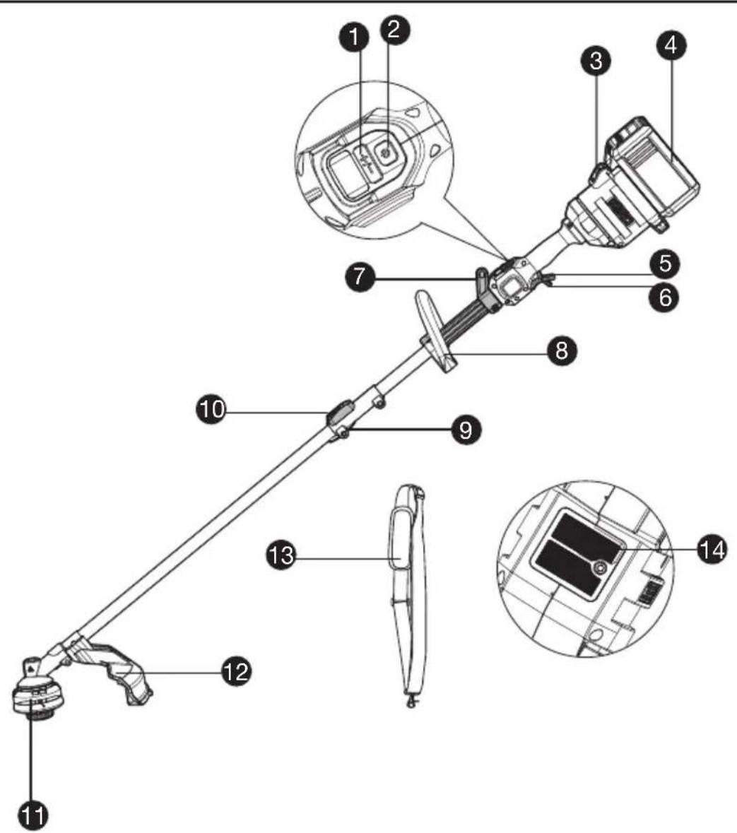
COMPONENT LIST
-
SPEED CONTROL
-
ON / OFF SWITCH
-
BATTERY PACK RELEASE
-
BATTERY PACK *
-
THROTTLE TRIGGER
-
SAFETY LOCK OFF LEVER
-
SHOULDER STRAP MOUNT
-
FRONT HANDLE
-
WING KNOB
-
SHAFT-RELEASE BUTTON
-
TRIMMER HEAD
-
DEBRIS GUARD
-
SHOULDER STRAP *
-
AIR FILTER
* Not all the accessories illustrated or described are included in standard delivery.
ORIGINAL INSTRUCTIONS GENERAL OUTDOOR POWER EQUIPMENT SAFETY WARNINGS
WARNING: Read all safety warnings, instructions, illustrations and specifications provided with this outdoor power equipment.
Failure to follow all instructions listed below may result in electric shock, fire and/or serious injury.
Save all warnings and instructions for future reference.
The term "outdoor power equipment" in the warnings refers to your corded outdoor power equipment or battery-operated (cordless) outdoor power equipment.
- Work area safety
a) Keep work area clean and well lit. Cluttered or dark areas invite accidents.
b) Do not operate outdoor power equipments in explosive atmospheres, such as in the presence of flammable liquids, gases or dust. Outdoor power equipments create sparks which may ignite the dust or fumes.
c) Keep children and bystanders away while operating a outdoor power equipment.
Distractions can cause you to lose control. - Electrical safety
a) Outdoor power equipment plugs must match the outlet. Never modify the plug in any way. Do not use any adapter plugs with earthed (grounded) outdoor power equipments. Unmodified plugs and matching outlets will reduce risk of electric shock.
b) Avoid body contact with earthed or grounded surfaces, such as pipes, radiators, ranges and refrigerators. There is an increased risk of electric shock if your body is earthed or grounded.
c) Do not operate the machine in rain or wet conditions. This may increase the risk of electric shock. If the machine becomes wet in the rain during operation, the machine and the battery should be dried before storing or charging. Remove the battery and reinsert it if the machine fails to turn on. Keep battery connection free of dirt and debris, and clean with a soft and dry brush or cloth.
d) Do not abuse the cord. Never use the cord for carrying, pulling or unplugging the outdoor power equipment. Keep cord away from heat, oil, sharp edges or moving parts. Damaged or entangled cords increase the risk of electric shock.
e) When operating a outdoor power equipment outdoors, use an extension cord suitable for outdoor use. Use of a cord suitable for outdoor use reduces the risk of electric shock.
f) If operating a outdoor power equipment in a damp location is unavoidable, use a residual
current device (RCD) protected supply. Use of an RCD reduces the risk of electric shock.
- Personal safety
a) Stay alert, watch what you are doing and use common sense when operating a outdoor power equipment. Do not use a outdoor power equipment while you are tired or under the influence of drugs, alcohol or medication.
A moment of inattention while operating outdoor power equipments may result in serious personal injury.
b) Use personal protective equipment. Always wear eye protection. Protective equipment such as dust mask, non-skid safety shoes, hard hat, or hearing protection used for appropriate conditions will reduce personal injuries.
c) Prevent unintentional starting. Ensure the switch is in the off-position before connecting to power source and/or battery pack, picking up or carrying the tool. Carrying outdoor power equipments with your finger on the switch or energizing outdoor power equipments that have the switch on invites accidents.
d) Remove any adjusting key or wrench before turning the outdoor power equipment on. A wrench or a key left attached to a rotating part of the outdoor power equipment may result in personal injury.
e) Do not overreach. Keep proper footing and balance at all times. This enables better control of the outdoor power equipment in unexpected situations.
f) Dress properly. Do not wear loose clothing or jewellery. Keep your hair, clothing and gloves away from moving parts. Loose clothes, jewellery or long hair can be caught in moving parts.
g) If devices are provided for the connection of dust extraction and collection facilities, ensure these are connected and properly used. Use of dust collection can reduce dust-related hazards.
h) Do not let familiarity gained from frequent use of tools allow you to become complacent and ignore tool safety principles. A careless action can cause severe injury within a fraction of a second. - Outdoor power equipment use and care
a) Do not force the outdoor power equipment. Use the correct outdoor power equipment for your application. The correct outdoor power equipment will do the job better and safer at the rate for which it was designed.
b) Do not use the outdoor power equipment if the switch does not turn it on and off.
Any outdoor power equipment that cannot be controlled with the switch is dangerous and must be repaired.
c) Disconnect the plug from the power source and/or the battery pack from the outdoor power equipment before making any adjustments, changing accessories, or storing outdoor power equipments. Such preventive
safety measures reduce the risk of starting the outdoor power equipment accidentally.
d) Store idle outdoor power equipments out of the reach of children and do not allow persons unfamiliar with the outdoor power equipment or these instructions to operate the outdoor power equipment. Outdoor power equipments are dangerous in the hands of untrained users.
e) Maintain outdoor power equipments. Check for misalignment or binding of moving parts, breakage of parts and any other condition that may affect the outdoor power equipment's operation. If damaged, have the outdoor power equipment repaired before use. Many accidents are caused by poorly maintained outdoor power equipments.
f) Keep cutting tools sharp and clean. Properly maintained cutting tools with sharp cutting edges are less likely to bind and are easier to control.
g) Use the outdoor power equipment, accessories and tool bits etc. in accordance with these instructions, taking into account the working conditions and the work to be performed. Use of the outdoor power equipment for operations different from those intended could result in a hazardous situation.
h) Keep handles and grasping surfaces dry, clean and free from oil and grease. Slippery handles and grasping surfaces do not allow for safe handling and control of the tool in unexpected situations.
- Battery tool use and care
a) Recharge only with the charger specified by the manufacturer. A charger that is suitable for one type of battery pack may create a risk of fire when used with another battery pack.
b) Use outdoor power equipments only with specifically designated battery packs. Use of any other battery packs may create a risk of injury and fire.
c) When battery pack is not in use, keep it away from other metal objects, like paper clips, coins, keys, nails, screws or other small metal objects, that can make a connection from one terminal to another. Shorting the battery terminals together may cause burns or a fire.
d) Under abusive conditions, liquid may be ejected from the battery; avoid contact. If contact accidentally occurs, flush with water. If liquid contacts eyes, additionally seek medical help. Liquid ejected from the battery may cause irritation or burns.
e) Do not use a battery pack or tool that is damaged or modified. Damaged or modified batteries may exhibit unpredictable behaviour resulting in fire, explosion or risk of injury.
f) Do not expose a battery pack or tool to fire or excessive temperature. Exposure to fire or temperature above 130 °C may cause explosion.
g) Follow all charging instructions and do not charge the battery pack or tool outside the temperature range specified in the instructions. Charging improperly or at temperatures outside the specified range may
damage the battery and increase the risk of fire.
- Service
a) Have your outdoor power equipment serviced by a qualified repair person using only identical replacement parts. This will ensure that the safety of the outdoor power equipment is maintained.
b) Never service damaged battery packs. Service of battery packs should only be performed by the manufacturer or authorized service providers.
BRUSH CUTTER AND BRUSH SAW SAFETY WARNINGS
a) Do not use the machine in bad weather conditions, especially when there is a risk of lightning. This decreases the risk of being struck by lightning.
b) Thoroughly inspect the area for wildlife where the machine is to be used. Wildlife may be injured by the machine during operation.
c) Thoroughly inspect the area where the machine is to be used and remove all stones, sticks, wires, bones, and other foreign objects. Thrown objects can cause personal injury.
d) Before using the machine, always visually inspect to see that the cutter or blade and the cutter or blade assembly are not damaged. Damaged parts increase the risk of injury.
e) Follow instructions for changing accessories. Improperly tightened blade securing nuts or bolts may either damage the blade or result in it becoming detached.
f) The rated rotational speed of the blade must be at least equal to the maximum rotational speed marked on the machine. Blades running faster than their rated rotational speed can break and fly apart.
g) Wear eye, ear, head and hand protection. Adequate protective equipment will reduce personal injury by flying debris or accidental contact with the cutting line or blade.
h) While operating the machine, always wear safety footwear. Do not operate the machine when barefoot or wearing open sandals. This reduces the chance of injury to the feet from contact with a moving cutter, line or blade.
i) While operating the machine, always wear long trousers. Exposed skin increases the likelihood of injury from thrown objects.
j) Keep bystanders away while operating the machine. Thrown debris can result in serious personal injury.
k) Always use two hands when operating the machine. Holding the machine with both hands will avoid loss of control.
I) Hold the machine by the insulated gripping surfaces only, because the cutting line or blade may contact hidden wiring. Cutting line or blades contacting a "live" wire may make exposed metal parts of the machine "live" and could give
the operator an electric shock.
m) Always keep proper footing and operate the machine only when standing on the ground. Slippery or unstable surfaces may cause a loss of balance or control of the machine.
n) Do not operate the machine on excessively steep slopes. This reduces the risk of loss of control, slipping and falling which may result in personal injury.
o) When working on slopes, always be sure of your footing, always work across the face of slopes, never up or down and exercise extreme caution when changing direction. This reduces the risk of loss of control, slipping and falling which may result in personal injury.
p) Keep all parts of the body away from the cutter, line or blade when the machine is operating. Before you start the machine, make sure the cutter, line or blade is not contacting anything. A moment of inattention while operating the machine may result in injury to yourself or others.
q) Do not operate the machine above waist height. This helps prevent unintended cutter or blade contact and enables better control of the machine in unexpected situations.
r) When cutting brush or saplings that are under tension, be alert for spring back. When the tension in the wood fibres is released, the brush or sapling may strike the operator and/or throw the machine out of control.
s) Use extreme caution when cutting brush and saplings. The slender material may catch the blade and be whipped toward you or pull you off balance.
t) Maintain control of the machine and do not touch cutters, lines or blades and other hazardous moving parts while they are still in motion. This reduces the risk of injury from moving parts.
u) Carry the machine with the machine switched off and away from your body. Proper handling of the machine will reduce the likelihood of accidental contact with a moving cutter, line or blade.
v) When transporting or storing the machine, always fit the cover on metal blades. Proper handling of the machine will reduce the likelihood of accidental contact with the blade.
w) Only use replacement cutters, lines, cutting heads and blades specified by the manufacturer. Incorrect replacement parts may increase the risk of breakage and injury.
x) When clearing jammed material or servicing the machine, make sure the switch is off and the battery pack is removed. Unexpected starting of the machine while clearing jammed material or servicing may result in serious personal injury.
BLADE THRUST CAUSES AND RELATED WARNINGS
Blade thrust is a sudden sideways, forward or backward motion of the machine, which may occur when the blade jams or catches on an object such as a sapling or a tree stump. It can be violent enough to cause the machine and/or operator to be propelled in any direction, and possibly lose control of the machine.
Blade thrust and its related hazards can be avoided by taking proper precautions as given below.
a) Maintain a firm grip with both hands on the machine and position your arms to resist blade thrust. Position your body to the left side of the machine. Blade thrust can increase the risk of injury due to the machine moving unexpectedly. Blade thrust can be controlled by the operator if proper precautions are taken.
b) If the blade binds, or when interrupting a cut for any reason, switch the machine off and hold the machine motionless in the material until the blade comes to a complete stop. While the blade is binding, never attempt to remove the machine from the material or pull the machine backward while the blade is in motion, otherwise blade thrust may occur. Investigate and take corrective actions to eliminate the cause of blade binding.
c) Do not use blunt or damaged blades. Blunt or damaged blades increase the risk of jamming or catching on an object, resulting in blade thrust.
d) Always maintain good visibility of the material being cut. Blade thrust is more likely to occur in areas where it is difficult to see the material being cut.
e) If you are approached by another person while operating the machine, switch the machine off. There is an increased risk of injury to other persons being struck by the moving blade in the event of blade thrust.
SAFETY WARNINGS FOR BATTERY PACK
a) Do not dismantle, open or shred cells or battery pack.
b) Do not short-circuit a battery pack. Do not store battery packs haphazardly in a box or drawer where they may short-circuit each other or be short-circuited by conductive materials. When battery pack is not in use, keep it away from other metal objects, like paper clips, coins, keys, nails, screws or other small metal objects, that can make a connection from one terminal to another. Shorting the battery terminals together may cause burns or a fire.
c) Do not expose battery pack to heat or fire. Avoid storage in direct sunlight.
d) Do not subject battery pack to mechanical shock.
e) In the event of battery leaking, do not allow the liquid to come into contact with the skin or eyes. If contact has been made, wash the
affected area with copious amounts of water and seek medical advice.
f) Keep battery pack clean and dry.
g) Wipe the battery pack terminals with a clean dry cloth if they become dirty.
h) Battery pack needs to be charged before use. Always refer to this instruction and use the correct charging procedure.
i) Do not maintain battery pack on charge when not in use.
j) After extended periods of storage, it may be necessary to charge and discharge the battery pack several times to obtain maximum performance.
k) Recharge only with the charger specified by Kress. Do not use any charger other than that specifically provided for use with the equipment.
I) Do not use any battery pack which is not designed for use with the equipment.
m) Keep battery pack out of the reach of children.
n) Retain the original product literature for future reference.
o) Remove the battery from the equipment when not in use.
p) Dispose of properly.
q) Do not mix cells of different manufacture, capacity, size or type within a device.
r) Keep the battery away from microwaves and high pressure.
s) Warning! Do not use non-rechargeable batteries.
USER MANUAL REQUIREMENTS FOR WIRELESS PRODUCT
a) Operation of this device is subject to the following two conditions:
(1) This device may not cause harmful interference, and
(2) this device must accept any interference received, including interference that may cause undesired operation.
b) Caution: Changes or modifications to this unit not expressly approved by the party responsible for compliance could void the user's authority to operate the equipment.
c) NOTE: This equipment generates, uses and can radiate radio frequency energy and, if not installed and used in accordance with the instructions, may cause harmful interference to radio communications. However, there is no guarantee that interference will not occur in a particular installation. If this equipment does cause harmful interference to radio or television reception, which can be determined by turning the equipment off and on, the user is encouraged to try to correct the interference by one or more of the following measures:
- Reorient or relocate the receiving antenna.
- Increase the separation between the equipment and receiver.
- Connect the equipment into an outlet on a circuit different from that to which the receiver is connected.
- Consult the dealer or an experienced radio/TV technician for help.
SYMBOLS
 | To reduce the risk of injury, user must read instruction manual |
 | Wear eye, ear and head protection |
 | Wear slip-resistant footwear |
 | WARNING – The distance between the machine and bystanders shall be at least 15 m (50 ft) |
 | WARNING – Beware of thrown objects. |
 | WARNING – Beware of blade thrust |
 | WARNING – Disconnect battery before maintenance |
 | Wear hand protection |
 | Waste electrical products must not be disposed of with household waste. Please recycle where facilities exist. Check with your local authorities or retailer for recycling advice. | |
| Environmentally friendly disposal Old electrical appliances must not be disposed of together with the residual waste, but have to be disposed of separately. The disposal at the communal collecting point via private persons is for free. The owner of old appliances is responsible to bring the appliances to these collecting points or to similar collection points. With this little personal effort, you contribute to recycle valuable raw materials and the treatment of toxic substances. | ||
| EN |  | Li-Ion battery This product has been marked with a symbol relating to 'separate collection' for all battery packs and battery pack. It will then be recycled or dismantled in order to reduce the impact on the environment. Battery packs can be hazardous for the environment and for human health since they contain hazardous substances. |
Li-Ion  | ||
 | Do not burn | |
 | Batteries may enter water cycle if disposed improperly, which can be hazardous for ecosystem. Do not dispose of waste batteries as unsorted municipal waste. | |
 | Make sure the battery is removed prior to changing accessories. | |
 | Trimming |
NOTE: Before using the tool, read the instruction book carefully.

BEFORE OPERATION:
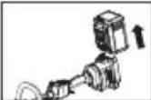
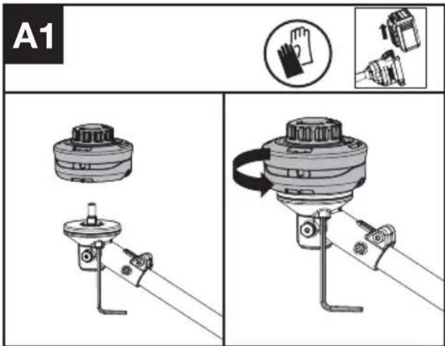
Assembling the cutting head (See Fig. A1)
Fit the cutting head. Insert the torx key into the hole and rotate the trimmer head counterclockwise until it stops in a locked position.
Assembling the debris guard (See Fig. A2)
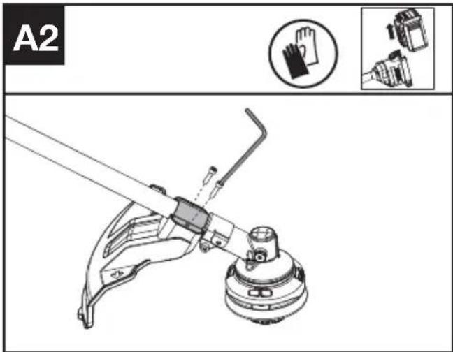
- Install the correct Debris Guard for the trimmer head.
- Secure the guard in place using the screw and torx key.
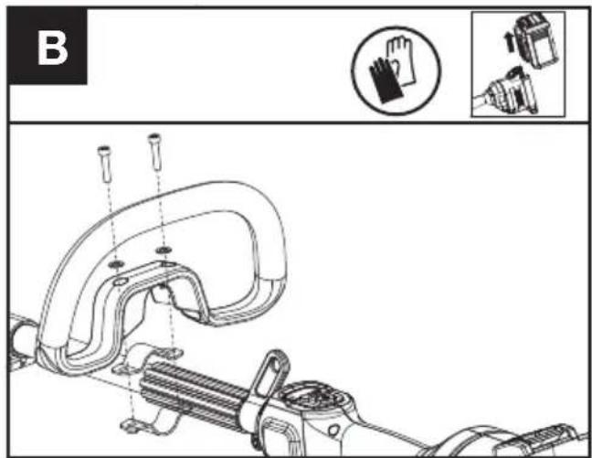
Assembling the Front Handle (See Fig. B)
- Attach the Front Handle and lower clamp on the shaft.
- Put the bolt through the holes.
- Tighten the Front Handle.

WARNING: Adjust the Front Handle as desired so as to make sure your front straight when using the trimmer.
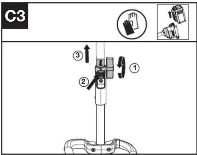
Assembling and disassembling the trimmer (See Fig. C1, C2, C3)
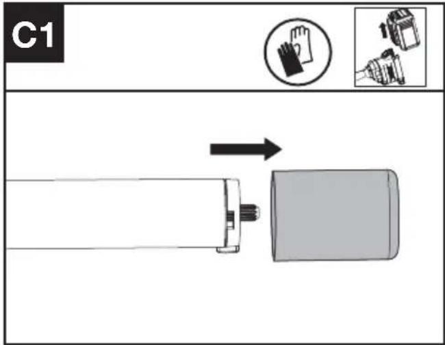
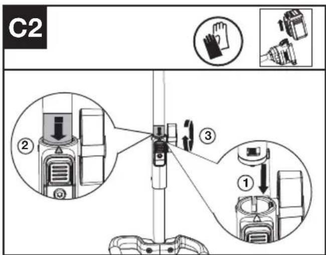
- Remove the protective cap from the end of the attachment shaft.
- To assemble, align the triangle icon on the button with the arrow label on the attachment shaft.
- Push the shafts together until you hear a "click". The edge of the arrow label should be close to the shaft connection housing.
- Finish the assembly by tightening the knob clockwise.
- To disassemble, loosen the knob, turn counter clockwise, then press the release button and
pull the shafts apart. Replace the protective cap on the attachment shaft to ensure that dust and debris do not get into the shaft.
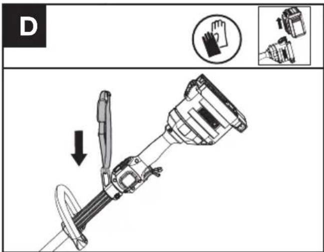
Fitting the shoulder strap (Sold Separately) (See Fig. D)
- Adjust the length of shoulder strap to make sure that the carabiner is about a hand's width below the top of your hip.
- Connect the carabiner of the accessory shoulder strap to the mounting point on the shaft of the trimmer.
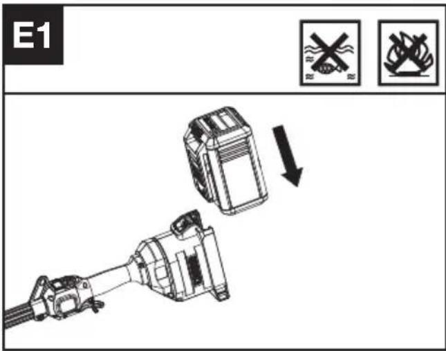
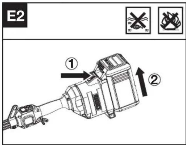
Installing & removing the battery pack (See Fig. E1, E2)
- Slide the battery pack into the battery compartment until you hear a click.
- Press the battery pack release to release battery pack from your tool.
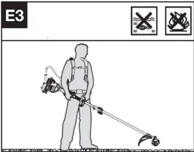
Connecting with the backpack harness (See Fig. E3)
The trimmer can be connected with an accessory backpack harness (not supplied). Refer to the backpack harness manual for more information.
TESTING THE TRIMMER AND BATTERY (See Fig. F)
Checking the controls Safety Lock Off Lever and Throttle Trigger
- Remove the battery.
- Try to press the Throttle Trigger. If the Throttle Trigger can be pressed without pushing the
Safety Lock Off Lever, the Safety Lock Off Lever is defective. Stop using the trimmer and contact the service agent.
- Push the Safety Lock Off Lever first, then press the Throttle Trigger.
- Release the Throttle Trigger and the Safety Lock Off Lever. If the Throttle Trigger or the Safety Lock Off Lever is stuck and cannot spring back to its original position. Stop using the trimmer and contact the service agent.

Checking the display
- Insert the battery.
- Press the on / off switch. The product is switched on when the LED (a) is lit. The product is switched off when the LED (a) is out.
- Push the Safety Lock Off Lever forward first, then squeeze and hold the throttle trigger to start the machine. (See Fig. G2)
- If the warning indicator (b) is flashing, refer to your dealer for solutions.
- Release the throttle trigger. The machine stops after a short delay. If the machine continues to operate, remove the battery and contact the service agent.
OPERATION: Starting the trimmer (See Fig. G1, G2)

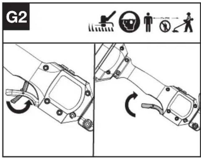
- Hold the trimmer firmly with your right hand on the control handle – wrap your thumb around the handle. Hold the trimmer with your left hand on the auxiliary handle– wrap your thumb around the handle.
- Press the On / Off Switch until the green LED is lit. The green LED shows the power level. Press the minus sign (-) on the speed control to select a lower cutting speed if needed.
- Push the Safety Lock Off Lever forward first, then squeeze and hold the throttle trigger to start the machine.
Selecting the speed
2 Power Levels can be selected depending on the application. Use the +/- to control the speed, which is as indicated by the LEDs. The higher the power level, the faster the tool runs.
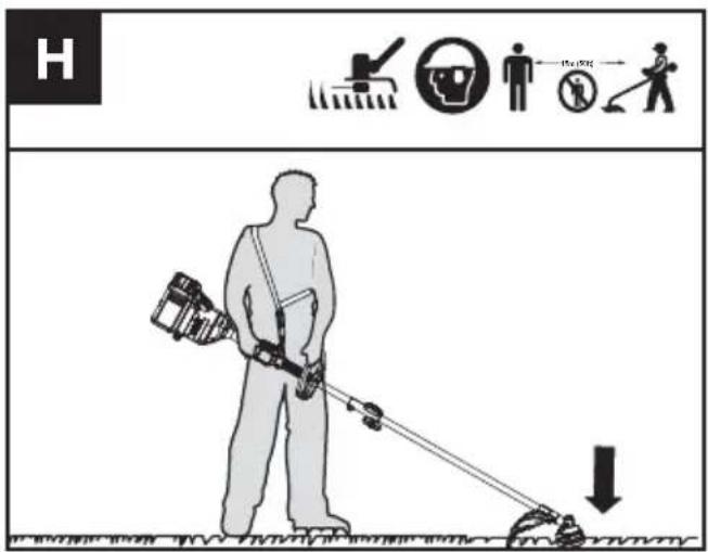
Bump-line feed system (See Fig. H)
The trimmer is equipped with a bump-line system. Just bump the trimmer head while the machine is running, new line will feed out.
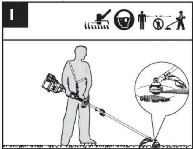
Cutting Tips (See Fig. I)
- Swing the trimmer from side to side across the area to be cut.
- Use the tip of the cutting line to do trimming; do not force the trimmer head into uncut grass.
- Wire and picket fences may cause extra cutting
line wear and breakage. Stone and brick walls, curbs, and wood may wear cutting line rapidly.
4. Avoid trees and shrubs. Tree bark, wood moldings, siding, and fence posts can easily be damaged by the cutting line.
5. The selected power level affects the battery's runtime. The lower the power level, the longer the runtime. It is recommended to use the lowest power level unless in worse cutting condition.
For Battery tools
The recommended ambient temperature range for discharging is -4^ 113^ ( -20^ 45^ ).
The recommended ambient temperature range for the charging system during charging is 23^ F\~ 113^ F (-5°C\~45°C).
TRANSPORTATION
Transporting the trimmer
- Switch off the trimmer and remove the battery.
- When transporting your trimmer by hand, hold the middle of the shaft with the cutting head to the rear and make sure that your machine is parallel to the ground.
- When transporting your trimmer in a vehicle, secure and position it to prevent movement or damage.
Transporting the battery
- Ensure the battery is in a safe condition.
- Use non-conductive packaging when transporting the battery.
- The contained Li-Ion batteries are subject to the dangerous goods legislation requirements.
Transport batteries only when the battery housing is undamaged. Pack up the batteries in such a manner that cannot move around in the packaging.
MAINTENANCE

WARNING! Always remove battery before conducting any maintenance on the trimmer.
Replacing the trimmer head (See Fig. J)

WARNING! Use of wire or metal-reinforced line is not authorized and could be
extremely dangerous. Use only the cutting line recommended in this manual, in combination with the recommended debris guard.

WARNING! A damaged or loose cutting attachment head may vibrate, crack, break
or come off the trimmer, which may result in serious or fatal injury or property damage. Make sure the trimmer head are properly and securely tightened and in good condition before starting work.
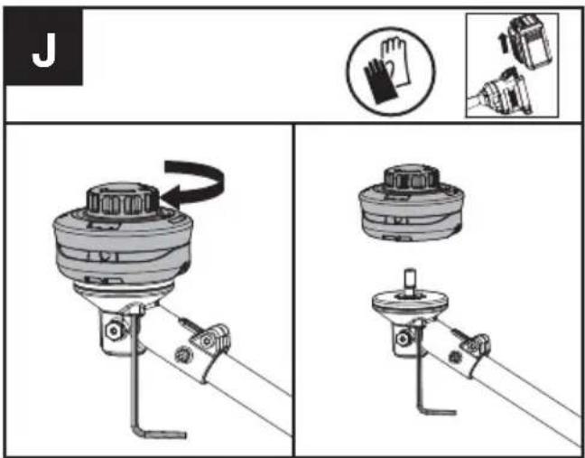
- Insert the torx key into the hole and rotate the trimmer head until it stops in a locked position.
- Then, rotate clockwise to remove it, and counterclockwise to assemble it. (See Fig. A1)
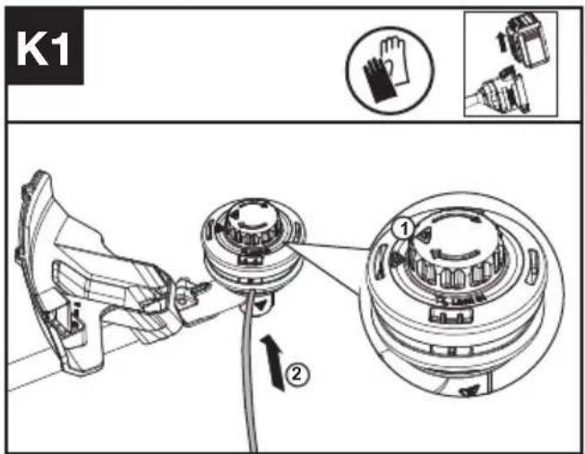
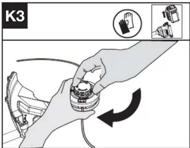
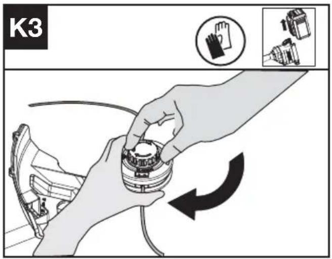
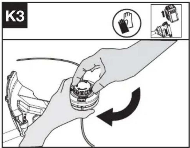
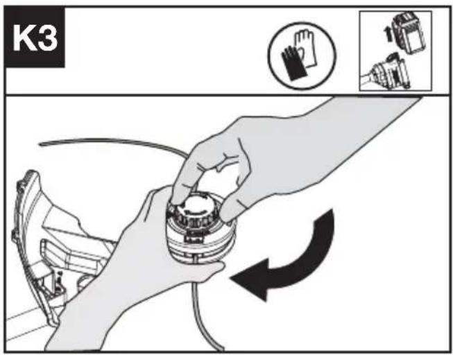
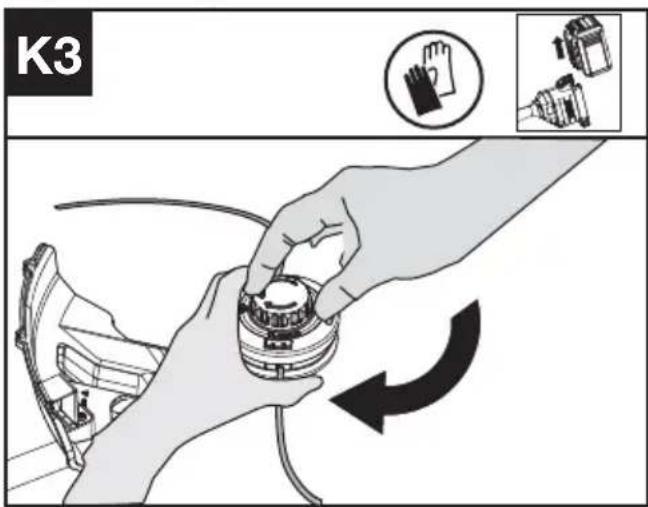
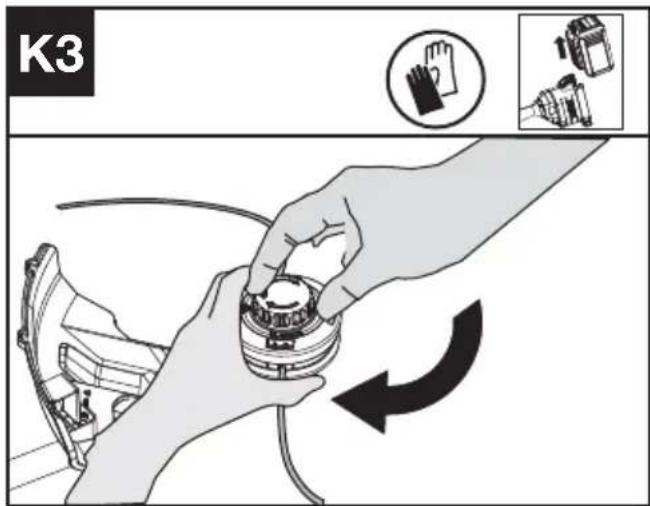
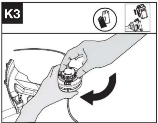
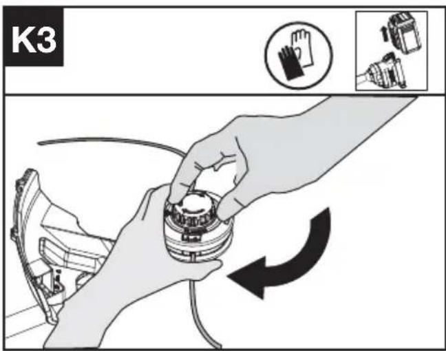
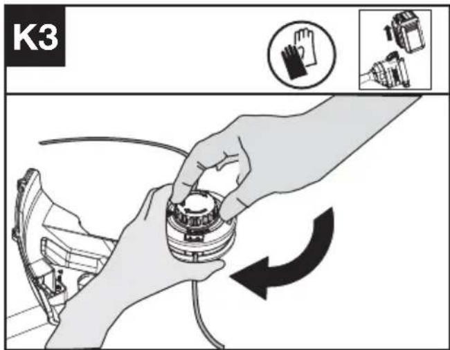
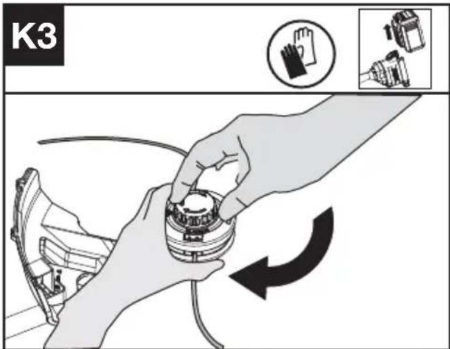
Winding the line (See Fig. K1, K2, K3)
- Rotate the spool cap until the two triangle icons are alighted. (See Fig. K1)
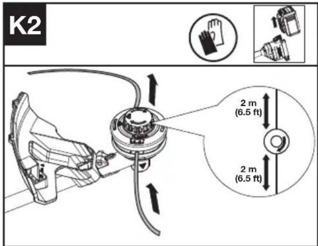

-
Insert the replacement line through the eyelet (Line In) and feed it out through the other eyelet. Ensure both ends of the line are even on each end of the trimmer head (recommended
2 m (6.5 ft) and cut the line. (See Fig. K2) -
Turn the dial clockwise to wind the line around the spool until about 6''(16 cm) remains on either side. (See Fig. K3)
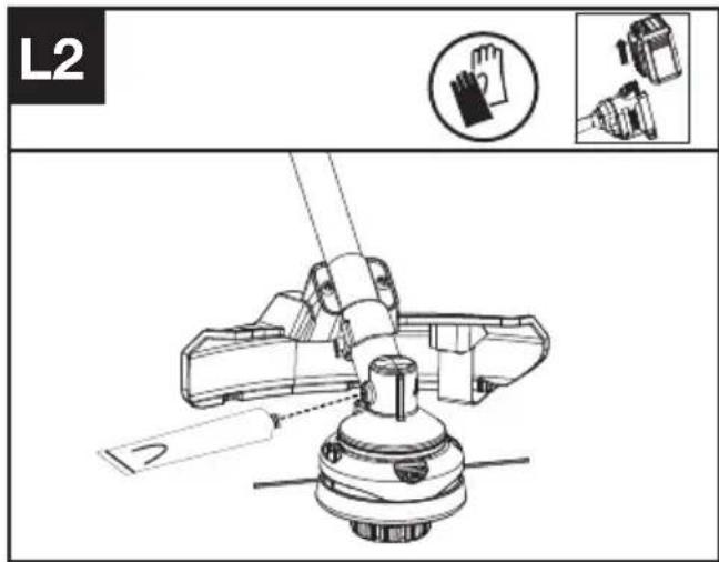
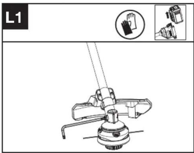
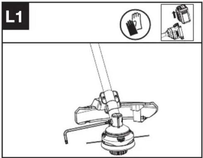
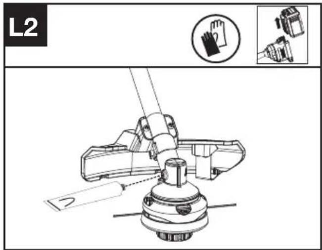
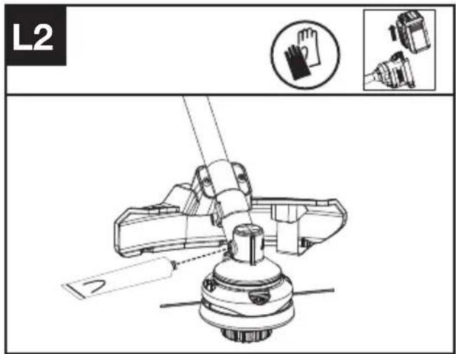
Lubricating the gearbox (See Fig. L1, L2)
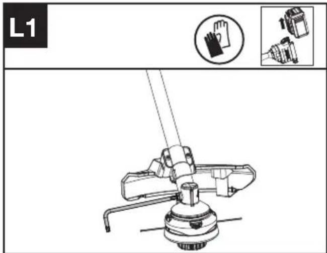
- Remove the screw on the gearbox.
-
If there is no bevel gear grease on the end of the screw, squeeze 5 g of the gear grease (SHELL Gadus S2 V220 1) into the gear housing.
-
Refit and tighten the screw firmly.
- Install the battery and run the trimmer for 1 minute to ensure the gear is evenly lubricated.
Cleaning the air filter (See Fig. M1, M2)
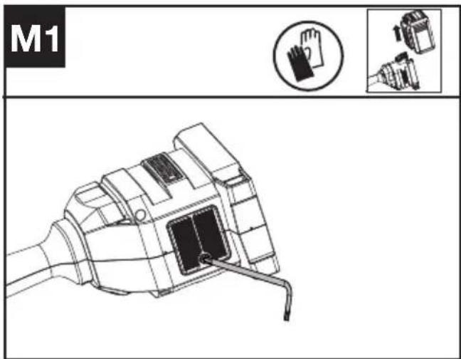
- Clean the area around the air filter. Use a damp cloth or a soft brush.
- Unscrew and remove the air filter.
- Wash the air filter with running water to remove the dirt.
- Allow the air filter to dry in the air. And then install it in the housing by thightening the screw.

Maintenance intervals
It is recommended to lubricate the gearbox and clean the air filter every 50 hours of operation based on actual usage.
CLEANING
- Switch off the trimmer and remove the battery.
- Do not use aggressive detergents or solvents. Clean the machine after use with a damp cloth dipped in mild detergent.
- Keep battery connection free of dirt and debris, and clean with a soft and dry brush or cloth.
- Do not spray water onto the motor and electrical components.
- Do not use pressure washer to clean your machine.
STORAGE
- Remove the battery pack from the trimmer before storage.
- If the machine becomes wet in the rain during operation, the machine and the battery should be dried before storing or charging. Remove the battery and reinsert it if the machine fails to turn on.
- Store the trimmer and the battery in a dry and secure place that is inaccessible to children and other unauthorized people.
Remove the cutting attachment if no use for a long time.
- Store the battery only within a temperature range between 41^ F ( 5^ C) and 77^ F ( 25^ C). As an example, do not leave the battery in the car in summer time.
TROUBLESHOOTING
The following table gives problems and actions that you can perform if your machine does not operate correctly.

WARNING: Switch the machine off and remove the battery prior to any troubleshooting.
TRIMMER
| Problems Possible | Causes Corrective Action | |
| Battery indicator LED flashing | Low battery voltage. Charge the battery. | |
| Red error LED flashing Overload. The cutting attachment is jammed. | ||
BATTERY
| Problems Possible | Causes Corrective Action | |
| Error LED lit The battery is discharged | charge the battery. If battery fails to charge, contact your Service Agent. | |
| Temperature issue. Use the battery in surroundings where temperatures are between 23°F and 113°F (-5°C and 45°C) for charge; -4°F to 113°F (-20°C to 45°C) for discharge. | ||
| Others Contact your Service Agent. | ||
TECHNICAL DATA
Type Designation: KC120 KC120.X (1-designation of machinery, representative of Cordless Grass Trimmer)
| KC120 KC120.X ** | |
| Voltage | 60 V --- Max. *** |
| Cutting speed | 4500 / 5900 rpm |
| Cutting diameter | 42cm |
| Line diameter | 2.4 / 2.7 mm nylon line |
| Degree of protection | IPX4 |
| Machine weight (Bare tool) | 4.3 kg |
** X=1-999,A-Z,M1-M9 they are only used for different customers, there are no safety relevant changes between these models.
*** Voltage measured without workload. Initial battery voltage reaches maximum of 60 volts. Nominal voltage is 54 volts.
SUGGESTED BATTERIES AND CHARGERS
| Battery Capacity | Charger Amperage | ||
| KAC804 4.0 Ah | KAC840 30 A | ||
| KAC810(With Backpack Harness) | 11.0 Ah |
We recommend that you purchase your accessories from the same Dealer that sold you the tool. Refer to the accessory packaging for further details. Your Dealer can assist you and offer advice.
TECHNICAL DATA FOR BATTERY PACK (OPTIONAL)
| Frequency bands for Bluetooth 2400-2483.5 MHz | |
| Maximum Output Power for Bluetooth | 8 dBm |
COMBINATIONS OF CUTTING ATTACHMENTS, DEFLECTORS, AND CARRYING SYSTEMS
| Cutting attachment Debris guard Barrier bar Carrying system | |||
| - 4" Trimmer head- 5" Trimmer head(Optional, not included) | - High-visibility deflector- Universal deflector with skirt | - Optional | - Shoulder strap (KAC130)- Backpack battery Harness (KAC900) |
| - Knife blade (KAC170) | - Universal deflector without skirt | - Required | |
COMPATIBLE ACCESSORY ATTACHMENTS
| Model Cutting attachment Model Cutting attachment | |||
| KAC104 | Power Head | KAC105 | Grass Trimmer Attachment |
| KAC141 | Straight Edger Attachment | KAC142 | Curved Edger Attachment |
| KAC200 | Hedger Trimmer Attachment | KAC360 | Extension Shaft(For use with KAC200/KAC361) |
| KAC361 | Pole Saw Attachment | ||
NOISE INFORMATION
| A weighted sound pressure L | _pA = 85 dB(A) |
| K_pA | 3 dB(A) |
| A weighted sound power L | _wA = 94 dB(A) |
| K_wA | 1.17 dB(A) |
| Wear ear protection. | |
VIBRATION INFORMATION
| Typical weighted vibration a | _h = 2.36 m/s^2 |
| Uncertainty K = 1.5 m/s^2 |
WARNING: The vibration emission value during actual use of the power tool can differ from the declared value depending on the ways in which the tool is used dependant on the following examples and other variations on how the tool is used:
How the tool is used and the materials being cut or drilled.
The tool being in good condition and well maintained The use the correct accessory for the tool and ensuring it is sharp and in good condition.
The tightness of the grip on the handles and if any anti vibration accessories are used.
And the tool is being used as intended by its design and these instructions.
This tool may cause hand-arm vibration syndrome if its use is not adequately managed.
WARNING: To be accurate, an estimation of exposure level in the actual conditions of use should also take account of all parts of the operating cycle such as the times when the tool is switched off and when it is running idle but not actually doing the job. This may significantly reduce the exposure level over the total working period.
Helping to minimise your vibration exposure risk. ALWAYS use sharp chisels, drills and blades Maintain this tool in accordance with these instructions and keep well lubricated (where appropriate) If the tool is to be used regularly then invest in anti vibration accessories.
Plan your work schedule to spread any high vibration tool use across a number of days.
ENVIRONMENTAL PROTECTION
Waste electrical products must not be disposed of with household waste. Please recycle where facilities exist. Check with your local authorities or retailer for recycling advice.
DECLARATION OF CONFORMITY
We, Positec Germany GmbH Postfach 680194, 50704 Cologne, Germany
On behalf of Positec declare that the product Description Cordless Grass Trimmer Type KC120 KC120.X (1-designation of machinery, representative of Cordless Grass Trimmer) Function cutting grass and similar soft vegetation and for trimming grass edges
Complies with the following Directives:
2006/42/EC, 2014/30/EU 2011/65/EU&(EU)2015/863 2000/14/EC amended by 2005/88/EC
2000/14/EC amended by 2005/88/EC: - Conformity Assessment Procedure as per Annex VI - Measured Sound Power Level 94 dB (A) - Declared Guaranteed Sound Power Level 96 dB (A)
The notified body involved Name: TÜV Rheinland LGA Products GmbH (Notified body 0197) Address: Tillystraße 2-90431 Nürnberg
The person authorized to compile the technical file, Name Marcel Filz Address Positec Germany GmbH Postfach 680194, 50704 Cologne, Germany

2024/01/17 Allen Ding Deputy Chief Engineer, Testing & Certification Positec Technology (China) Co., Ltd 18, Dongwang Road, Suzhou Industrial Park, Jiangsu 215123, P. R. China
DECLARATION OF CONFORMITY
We,
Positec (UK & Ireland) Ltd
PO Box 6242, Newbury, RG14 9LT, UK
On behalf of Positec declare that the product
Description Cordless Grass Trimmer
Type KC120 KC120.X (1-designation of machinery, representative of Cordless Grass Trimmer)
Function cutting grass and similar soft vegetation and for trimming grass edges
Complies with the following regulations:
Supply of Machinery (Safety) Regulations 2008
Electromagnetic Compatibility Regulations 2016
The Restriction of the Use of Certain Hazardous
Substances in Electrical and Electronic
Equipment Regulations
Noise Emission in the Environment by Equipment for Use Outdoors Regulations
- Conformity Assessment Procedure as per SCHEDULE 9
- Measured Sound Power Level 94 dB (A)
- Declared Guaranteed Sound Power Level 96 dB (A)
The notified body involved
Name: TÜV Rheinland LGA Products GmbH
(Notified body 0197)
Address: Tillystraße 2-90431 Nürnberg
Standards conform to
BS EN 62841-1, FprBS EN IEC
62841-4-4:2020+FprAA:2021-02, BS EN 62233,
BS EN ISO 3744, BS EN IEC 55014-1, BS EN IEC
55014-2, BS EN IEC 63000
The person authorized to compile the technical file,
Name Jim Kirkwood
Address Positec (UK & Ireland) Ltd,
PO Box 6242, Newbury, RG14 9LT, UK


2024/01/17
Allen Ding
Deputy Chief Engineer, Testing & Certification
Positec Technology (China) Co., Ltd
18, Dongwang Road, Suzhou Industrial
Park, Jiangsu 215123, P. R. China
INHALTSVERZEICHNIS
Einführung....18
Komponenten....19
KOMPONENTEN
TESTBETRIEB DES TRIMMERS UND DES AKKUPACKS (SIEHE ABB. F)
Bei Akkuwerkzeugen

| A weighted sound pressure L | _pA = 85 dB(A) |
| K_pA | 3 dB(A) |
| A weighted sound power L | _wA = 94 dB(A) |
| K_wA | 1.17 dB(A) |
18, Dongwang Road, Suzhou Industrial
Park, Jiangsu 215123, P. R. China
SOMMAIRE
Introduction....34
LISTE DES COMPOSANTS
-
BOUTONS DE RÉGLAGE DE LA VITESSE
-
INTERRUPTEUR MARCHE/ARRÊT
-
VERROU DE PACK BATTERIE
-
PACK BATTERIE *
-
MANETTE DES GAZ
-
LEVIER DE DÉSACTIVATION DE SÉCURITÉ
-
SUPPORT DE BANDOULIÈRE
-
FRONT HANDLE
-
BOUTON À AILETTES
-
BOUTON DE DÉVERROUILLAGE D'ARBRE
-
TÊTE DE COUPE
-
PROTECTION ANTI-DÉBRIS
-
BANDOULIÈRE *
-
FILTRE À AIR
INFORMATIONS RELATIVES AU BRUIT
INFORMATIONS RELATIVES AUX VIBRATIONS
18, Dongwang Road, Suzhou Industrial
Park, Jiangsu 215123, P. R. ChinaWe,
INDICE
Introduzione....50
ELEMENTI DELL'APPARECCHIO
-
CONTROLLO DELLA VELOCITA'
-
INTERRUTTORE ON/OFF
-
SERRATURA A SCATTO UNITÀ BATTERIA
-
UNITÀ BATTERIA *
-
GRILLETTO DELL'ACCELERATORE
-
LEVA DI SICUREZZA DISATTIVAZIONE
-
SUPPORTO PER TRACOLLA
-
MANIGLIA ANTERIORE
-
MANOPOLA AD ALETTE
-
PULSANTE DI RILASCIO DELL'ALBERO
-
TESTA DI TAGLIO
-
PROTEZIONE ANTI-DETRITI
-
TRACOLLA *
-
FILTRO DELL'ARIA
PER GLI UTENSILI A BATTERIA
18, Dongwang Road, Suzhou Industrial
Park, Jiangsu 215123, P. R. China
ÍNDICE
Introducción....66

18, Dongwang Road, Suzhou Industrial
Park, Jiangsu 215123, P. R. China
ÍNDICE
Introdução....82
Lista de componentes....83
PARA FERRAMENTAS ELÉTRICAS

Lubrificar a caixa de engrenagens (Ver a Fig. L1, L2)
18, Dongwang Road, Suzhou Industrial
Park, Jiangsu 215123, P. R. China
INHOUDSOPGAVE
Inleiding....98
DRIE SNELHEIDSINSTELLINGEN
-
SNELHEIDSREGELING
-
AAN/UIT-SCHAKELAAR
-
ONTGRENDELPAL ACCU
-
ACCUPACK *
-
GASHENDEL
-
VEILIGHEIDSONTGRENDELINGSHENDEL
-
SCHOUDERRIEMBEVESTIGING
-
VOORSTE HANDGREEP
-
VLEUGELKNOP
-
STEELONTGRENDELINGSKNOP
-
FIJNAFSTEMMINGSKOP
-
BESCHERMKAP
-
SCHOUDER RIEM *
-
LUCHTFILTER
VEILIGHEIDSWAARSCHUWINGEN
VOOR BOSMAAIERS EN GRASTRIMMERS
VOOR GEREEDSCHAP MET ACCU'S
18, Dongwang Road, Suzhou Industrial
Park, Jiangsu 215123, P. R. China
TARTALOMJEGYZÉK
Bevezető....114

18, Dongwang Road, Suzhou Industrial
Park, Jiangsu 215123, P. R. China
CUPRINS
Introducere....130
LISTA DE COMPONENTE
-
CONTROLUL VITEZEI
-
BUTON DE PORNIRE/OPRIRE
-
BUTON DE ELIBERARE A ACUMULATORULUI
-
ACUMULATOR *
-
BUTONUL DE ACCELERATIE
-
MANETĂ DE BLOCARE A SIGURANȚEI
-
SUPORT CUREA DE UMĂR
-
MÂNERULUI FRONTAL
-
BUTON PENTRU ARIPĂ
-
BUTON PENTRU ELIBERAREA TIJEI
-
CAP DE REGLARE FINĂ
-
PROTECTIEI ÎMPOTRIVA RESTURILOR
-
CUREA DE UMĂR *
-
FILTRU DE AER
INSTRUCTIUNI ORIGINALE SECURITATEA PRODUSULUI AVERTISMENTE GENERALE DE SIGURANTĂ PENTRU UNELTE ELECTRICE
acelor de ceasornic.
Ungerea transmisiei (a se vedea Fig. L1, L2)
18, Dongwang Road, Suzhou Industrial
Park, Jiangsu 215123, P. R. China
SPIS TREŚCI
Wprowadzenie....146
LISTA KOMPONENTÓW
-
REGULATOR PRĘDKOŚCI
-
WŁĄCZNIK/WYŁĄCZNIK
-
ZATRZASK POJEMNIKA BATERYJNEGO
-
ZESTAW BATERII *
-
WYZWALACZ PRZEPUSTNICY
-
DŻWIGNIA BLOKADY BEZPIECZEŃSTWA
-
MOCOWANIE NA PASEK NA RAMIĘ
-
FRONT HANDLE
-
POKRETŁO SKRZYDEŁKOWE
-
PRZYCISK ZWALNIANIA WAŁKA
-
UCHWYTU PRZEDNIEGO
-
OSŁONY PRZED ŚMIECIAMI
-
PASEK NA RAMIĘ *
-
FILTR POWIETRZA
18, Dongwang Road, Suzhou Industrial
Park, Jiangsu 215123, P. R. China
OBSAH
Úvod....162
SEZNAM KOMPONENT
- REGULACE RYCHLOSTI
- HLAVNÍ VYPÍNAČ
- UVOLŇOVACÍ TLAČÍTKO BATERIE
- AKUMULÁTOR *
- SPOUŠT ŠKRTICÍ KLAPKY
- BEZPEČNOSTNÍ ODJIŠTOVACÍ PÁKA
- DRŽÁK NA RAMENNÍ POPRUH
- PŘEDNÍ RUKOJETI
- KŘÍDLOVÝ ŠROUB
- TLAČÍTKO PRO UVOLNĚNÍ HŘÍDELE
- JEMNĚ VYLADĚNÁ HLAVA
- OCHRANNÉHO KRYTU PROTI NEČISTOTÁM
- RAMENNÍ POPRUH *
- VZDUCHOVÝ FILTR
PŮVODNÍ NÁVOD K POUŽÍVÁNÍ BEZPEČNOST VÝROBKU OBECNÁ BEZPEČNOSTNÍ UPOZORNĚNÍ PRO ELEKTRICKÉ NÁSTROJE

ZKOUŠKA STRUNOVÉ SEKAČKY A BATERIE (VIZ OBR. F)
Volba rychlosti
INFORMACE TÝKAJÍCÍ SE HLUČNOSTI
18, Dongwang Road, Suzhou Industrial
Park, Jiangsu 215123, P. R. China
OBSAH
Úvod....178
ZOZNAM SÚČASTÍ
-
OVLÁDANIE RÝCHLOSTI
-
TLAČIDLO ZAPNÚŤ/VYPNÚŤ
-
UVOLŇOVACÍ TLAČÍTKO BATERIE
-
BATÉRIOVÝ *
-
ŠKRTIACA KLAPKA
-
PÁKA BEZPEČNOSTNÉHO ZÁMKU
-
DRŽIAK NA RAMENNÝ POPRUH
-
PREDNEJ RUKOVÄTE
-
KRÍDLOVÝ OTOČNÝ GOMBÍK
-
TLAČIDLO NA UVOL'NENIE HRIADEL'A
-
JEMNE VYLADENÁ HLAVA
-
OCHRANNÉHO KRYTU PROTI ÚLOMKOM
-
RAMENNÝ POPRUH *
-
VZDUCHOVÝ FILTER
18, Dongwang Road, Suzhou Industrial
Park, Jiangsu 215123, P. R. China
KAZALO VSEBINE
Uvod....194
Sestavni deli....195
Varnost izdelka....196
Sestavljanje in delovanje....201
Transport....204
Vzdrževanje....204
Čiščenje....206
Shranjevanje....206
SESTAVNI DELI
-
KRMILNIK HITROSTI
-
STIKALO ZA VKLOP/IZKLOP
-
GUMB ZA SPROSTITEV AKUMULATORJA
-
AKUMULATOR *
-
SPROŽILEC PLINA
-
VARNOSTNA ROČICA ZA ZAKLEPANJE
-
NASTAVEK ZA NARAMNICO
-
SPREDNJEGA ROČAJA
-
KRILNI VIJAK
-
GUMB ZA SPROSTITEV GREDI
-
GLAVA ZA FINO NASTAVITEV
-
ŠČITNIKA ZA OBREZKE
-
NARAMNI PAS *
-
ZRAČNI FILTER
Nasveti za rezanje (Glej sliko I)
Za akumulatorska orodja

Mazanje menjalnika (glej sliki L1, L2)
- Odstranite vijake na menjalniku.
- Če na koncu vijaka ni maziva za stožčasti zobnik, stisnite 5 g maziva (SHELL Gadus S2 V220 1) za prestavo v ohišje prestave.
- Ponovno namestite in trdno privijte vijake.
- Namestite baterijo in zaženite obrezovalnik za 1 minuto, da zagotovite enakomerno mazanje prestave.
POPIS KOMPONENTI
-
KONTROLA BRZINE
-
PREKIDAČ ON/OFF (UKLJUČENO/ISKLJUČENO)
-
OTVARANJE BATERIJSKOG MODULA
-
BATERIJSKI KOMPLET *
-
AKTIVATOR GASA
-
RUČICA ZAKLJUČAVANJA SIGURNOSTI
-
MONTIRANJE NARAMENICE
-
PREDNJA RUČKA
-
KRILNA RUČICA
-
GUMB ZA OTPUŠTANJE OSOVINE
-
GLAVA TRIMERA
-
ŠTITNIK OD KRHOTINA
-
NARAMENICA*
-
FILTAR ZRAKA
* Standardna isporuka ne obuhvaća sav ilustriran ili opisan pribor.
ORIGINALNE UPUTE ZA RAD SIGURNOST PROIZVODA UOBIČAJENA SIGURNOSNA UPOZORENJA ZA ELEKTRIČNE ALATE

UPOZORENJE Pročitajte sva sigurnosna upozorenja, upute, ilustracije i specifikacije
Rezanje vrhova (podrezivanje) (vidi sl. I)
- Zanjihajte trimer s jedne na drugu stranu preko područja koje želite rezati.
- Upotrijebite vrh rezne niti (flaksa) za podrezivanje; nemojte silom gurati glavu trimera u nepokošenu
travu.
ZA BATERIJSKE ALATE
- Umetnite zamjensku nit kroz ušicu (nit unutra) i provucite ju kroz vanjsku ušicu. Uvjerite se da su oba kraja niti jednaka s obje strane glave trimera (preporučeno 2 m (6.5 ft)) i odrežite nit. (vidi sl. K2)
- Okrenite kotačić u smjeru kazaljke na satu kako biste namotali nit oko kalema dok ne ostane oko 16 cm (6") s obje strane. (vidi sl. K3)
Podmazivanje reduktora (vidi sl. L1, L2)

- Uklonite vijak s reduktora.
- Ako na kraju vijka nema masti za konusne zupčanike, istisnite 5 g masti (SHELL Gadus S2 V220 1) za zupčanike u kućište zupčanika.
-
Vratite vijak i zategnite ga.
-
Umetnite bateriju i upalite trimer na 1 minutu kako biste se uvjerili da je zupčanik ravnomjerno podmazan.
18, Dongwang Road, Suzhou Industrial
Park, Jiangsu 215123, P. R. China
INDHOLDSFORTEGNELSE
Introduktion....225
TEST AF TRIMMEREN OG BATTERIET (SE FIG. F)
Valg af hastighed
Type KC120 KC120.X (1-dpegning af
18, Dongwang Road, Suzhou Industrial
Park, Jiangsu 215123, P. R. China
SISÄLLYSLUETTELO
Johdanto....240
Komponenttiluettelo....241
KOMPONENTTILUETTELO
-
NOPEUDENSÄÄTÖ
-
ON/OFF-VIRTAKYTKIN
-
AKKUYKSIKÖN VAPAUTUSPAINIKE
-
AKKUYKSIKKÖ *
-
KAASULIIPAISIN
-
TURVALUKON VAPAUTUSVIPU
-
OLKAHIHNAN ASENNUSKOHTA
-
ETUKAHVA
-
SIIPIMUTTERI
-
VARREN VAPAUTUSPAINIKE
-
TRIMMERIPÄÄ
-
ROSKASUOJA
-
OLKAHIHNA *
-
ILMANSUODATIN
Transportation....264
Vedlikehold....264
Rengjøring....266
Lagring....266
Feilsøking....267
APPARATELEMENTER
- HASTIGHETSKONTROLL
- AV/PÅ-BRYTER
- LÅS FOR BATTERIPAKKE
- BATTERIPAKKE *
- GASSBRYTER
- SIKKERHETSLÅSSPAKE
- SHOULDER STRAP MOUNT
- HÅNDTAKET FORAN
- VINGEKNOTT
- SKAFTUTL∅SERKNAPP
- FINJUSTERINGSHODE
- BESKYTTELSESSKJERMEN
- SKULDERREM *
- LUFTFILTER
ORIGINAL DRIFTSINSTRUKS PRODUKTSIKKERHET GENERELLE ADVARSLER FOR ELEKTROVERKT∅Y

ADVARSEL Les alle
TESTE TRIMMEREN OG BATTERIET (SE FIG. F)
Valg av hastighet
Vedlikeholdsintervaller
Smøre girboksen (se fig. L1, L2)
18, Dongwang Road, Suzhou Industrial
Park, Jiangsu 215123, P. R. China
INNEHÅLLSFÖRTECKNING
Introduktion....270
Komponenter....271
Produktsäkerhet 272
Transportation....279
Underhåll 279
Rengöring....281
Förvaring....281
Felsökning....282
Tekniska data....282
Miljöskydd....284
KOMPONENTER
-
HASTIGHETSKONTROLL
-
STRÖMBRYTARE PÅ/AV
-
BATTERIPAKETETS LÅSNING
-
BATTERI *
-
GASREGLAGE
-
SÄKERHETSLÅSSPAK
-
AXELREMSFÄSTE
-
FRÄMRE HANDTAG
-
VINGVRED
-
SKAFTETS SLÄPPKNAPP
-
TRIMMERHUVUD
-
STÄNKSKYDD
-
AXELREM *
-
LUFTFILTER
TEST AV TRIMMMER OCH BATTERI (SE FIGUR F)
Välja hastighet
Klipptips (Se Figur I)
För batteriverktyg
This should be an app notifications after running product for 50h
RENGÖRING
KOMPATIBLA TILLBEHÖR