
F5 - Headphones Interphone - Free user manual and instructions
Find the device manual for free F5 Interphone in PDF.

User questions about F5 Interphone
0 question about this device. Answer the ones you know or ask your own.
Ask a new question about this device
Download the instructions for your Headphones in PDF format for free! Find your manual F5 - Interphone and take your electronic device back in hand. On this page are published all the documents necessary for the use of your device. F5 by Interphone.
USER MANUAL F5 Interphone
interphone

interphone


natural_image
Close-up of a black interphone with four blades and a screw base (no visible text or symbols)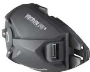
natural_image
Close-up of a black mechanical device with a USB port, no visible text or symbolsIT Manuale di Istruzioni....18
EN Instruction manual 28
FR Mode d'emploi 38
ES Manual operativo 48
DE Bedienungsanleitungen....58
CS Návod k použití....68
NL Handleiding 78
RU Руководство по эксплуатации ..... 88
PL Instrukcja obsługi 98
SV Bruksanvisning 108
Käyttöohjc 118
PT Manual do utilizador....128
JP
interphone F5
natural_image
Black and white photo of a pair of 500-meter earpluses with earbuds, shown against a plain white background (no text or symbols visible)STRINGHE VOCE GUIDA
VOICE WIZARD PHRASES
| ON/OFF | Interphone FS Powering down |
| ON/OFF | Interphone FS Ready |
| ON/OFF | connected to phone |
| ON/OFF | no phone found |
| Intercom | Intercom |
| Intercom | Press up button until the beep to connect the last paired intercom |
| Intercom | Down button until the beep for the previous |
| Intercom | Centre button until the beep for bath |
| Intercom | Short press down button for Phone menu |
| Intercom | up button for Setup menu |
| Intercom | Intercom Active, press centre button to disconnect |
| Intercom | no Intercom paired |
| Intercom | disconnecting intercom |
| Intercom | Connecting to intercom |
| Intercom | Intercom connection failed |
| Intercom | intercom disconnected |
| Phone | Phone |
| Phone | Press centre button to select Phone menu |
| Phone | press down button for FM menu |
| Phone | up button for Intercom menu |
| Phone | Phone mode |
| Phone | Press down button to voice dial |
| Phone | up button to redial |
| Phone | Call Rejected |
| Phone | Ring Muted |
| Phone | Redailing last number |
| Phone | Voice Dial |
| FM | FM |
| FM | Press centre button to activate FM |
| FM | press down button for music streaming menu |
| FM | up button for Phone menu |
| FM | FM Active |
| FM | press up or down button until the beep to Scan |
| FM | press centre button until the beep to Store |
| FM | Memory one |
| FM | Memory two |
| FM | Memory three |
| FM | Memory four |
| FM | Memory five |
| FM | Memory six |
| FM | Memory seven |
| FM | Memory eight |
| FM | Scan up |
| FM | Scan down |
| FM | Press up or down button to select memory |
| FM | Press Centre Button to store |
| FM | FM station stored to |
| FM | No station stored |
| A2DP | Music Streaming |
| A2DP | Press centre button to select music streaming menu |
| A2DP | press down button for Auxiliary input menu |
| A2DP | up button for FM menu |
| A2DP | Music Streaming Active |
| A2DP | press centre button until the beep to play or pause |
| A2DP | Press up or down button to select a track |
| A2DP | Next |
| A2DP | Previous |
| A2DP | Music Paused |
| Auxiliary input Auxiliary input | |
| Auxiliary Input Press centre button to activate Auxiliary input | |
| Auxiliary input press down button for Setup menu | |
| Auxiliary Input up button for music streaming menu | |
| Auxiliary input Auxiliary input Active | |
| Setup Menu | Setup |
| Setup Menu | Press centre button to select Setup menu |
| Setup Menu | press down button for Intercom menu |
| Setup Menu | up button for Auxiliary input menu |
| Setup Menu | Setup Active |
| Setup Menu | R D S ON |
| Setup Menu | R D S OFF |
| Setup Menu | Press centre button until the beep to change R D S settings |
| Setup Menu | Press down button for Caller ID settings |
| Setup Menu | Up button for Erase Pairings menu |
| Setup Menu | Caller I D ON |
| Setup Menu | Caller I D OFF |
| Setup Menu | Press centre button until the beep to change Caller I D settings |
| Setup Menu | Press down button for Volume Control settings |
| Setup Menu | Up button for R D S settings |
| Setup Menu | Automatic Volume Control ON |
| Setup Menu | Automatic Volume Control OFF |
| Setup Menu | Press centre button until the beep to change Volume Control settings |
| Setup Menu | Press down button for Voice answer settings |
| Setup Menu | Up button for Caller I D settings |
| Setup Menu | Voice answer ON |
| Setup Menu | Voice answer OFF |
| Setup Menu | Press centre button until the beep to change Voice answer settings |
| Setup Menu | Press down button for Erase Pairings menu |
| Setup Menu | Up button for Volume Control settings |
| Setup Menu | Erase Pairings |
| Setup Menu | Press centre button until the beep to erase pairings |
| Setup Menu | Press down button for RDS settings |
| Setup Menu | Up button for Voice answer settings |
| Setup Menu | All pairings will be erased |
| Setup Menu | Short press centre button to cancel, press until the beep to erase |
| Setup Menu | Pairings erased |
| Pairing | Press on centre button to select British English |
| Pairing | British English selected |
| Pairing | From phone Bluetooth ^® menu |
| Pairing | Search for devices |
| Pairing | And select Interphone FS |
| Pairing | Enter Pin code 0000 if requested |
| Pairing | Intercom Device Search |
| Pairing | Intercom Found |
| Pairing | Pairing cancelled |
| Pairing | Factory reset |
| Pairing | Version |
| Pairing | No Intercom found |
| Pairing | Pairing successful |
| Phone | Not supported by phone |
PHRASES VOIX DE GUIDAGE
www.interphone.cellularline.com
www.interphone.cellularline.com
PRODUCT DESCRIPTION 29
CARE AND MAINTENANCE 29
1.0 PREPARATION/INSTALLATION 30
1.1 Charging....30
1.2 Installing the bracket on the helmet.... 30
1.3 Audio section 31
1.4 Latching the F5 module onto the helmet..... 32
1.5 Connecting the FS module to the audio kit..... 32
1.6 Removing the F5 module from the helmet ..... 32
1.7 Turning on the FS module 32
1.8 Shutting off the F5 module 32
1.9 Adjusting the volume 32
2.0 PAIRING 32
2.1 Procedure for pairing with Bluetooth ^® devices ..... 33
2.2 Procedure for pairing two InterphoneF5s..... 34
2.3 Procedure for pairing three InterphoneF5s..... 35
2.4 Procedure for "Conference" pairing of four
InterphoneFSs 35
2.5 Procedure for "Conference" pairing of more than
four InterphoneFSs.... 35
3.0 NOTES AND GENERAL RECOMMENDATIONS ..... 36
3.1 Device shutdown.... 36
3.2 Range.... 36
3.3 Electromagnetic compatibility.... 36
3.4 Operating precautions 36
3.5 Voice wizard phrases.... 36
Introduction
INTERPHONEFS
Thanking you for the appreciation you have shown for Cellular Line products, Cellular Italia S.p.A. wishes to provide you with the useful information contained in this manual.
The InterphoneF5 is a Bluetooth® device for helmets that can provide wireless communication among a number of users, thanks to Bluetooth® 3.0 technology.
With its quick fasten/release bracket, InterphoneF5 can be installed on most helmets, and the ergonomic shape of the control module makes it easy to operate the keys, even while wearing gloves.
The InterphoneF5 module is covered with a special film that protects against the weather (Weather protection skin system) and enables the unit to withstand extreme outdoor conditions. The entire Interphone F series is certified to offer an IP 67 level of protection.
Package contents
a) Bluetooth® module (r)
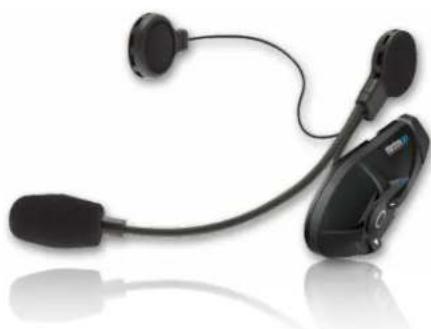
b) Stereo earphone equipped with a microphone with foam windscreen, on a flexible arm (universal)
c) Stereo earphone with wired microphone for full-face helmets d) Removable clip-on support
e) Permanent adhesive-based support
al USB cable
h) Extendable cable for audio connections (2.5 mm/3.5 mm) i) Velcro adhesive strips
j) Clip adapter
K) Screwdriver II User manual
NOTES: in the package containing two FS kits, components
a - b - c - d - e - h - l - j - k are doubled.
Product description
InterphoneF5 Bluetooth ^® module
1) MFB (multifunction button) 2) More UP button
8) Multifunction socket for charger and accessories
9) Mounting guides for Bluetooth® module
Audio unit for open-face and modular helmets
10) Left earphone 13) Right earphone
12] Left/right earphone connectors
13| Microphone/foam windscreen
Audio unit for full-face helmets
16) Left Earphone 17) Right Earphone
181 Earphone connectors
19) Microphone/foam windscreen
20| Audio connector plug
21; 2.5 mm AUX-IN SOCKET
Care and maintenance
If you do not use the kit for an extended period of time, charge the battery every 2 to 3 months to prevent damage.
To clean, use a damp sponge and (if necessary) mild soap. Do not
use solvents or degreasing products to clean the module.
important to prevent water from seeping in through the audio connector and damaging the module during cleaning, be sure
to insert the plug from the audio section into the socket, as when the unit is installed and used on the helmet. The kit is waterweight
the drift is installed and used on the helix. The kit is water rights only when the audio plug is inserted.
IMPORTANT: If radio interference is high due to the vicinity of
repeaters, high voltage towers or various kinds of radio signals, intercom communication and/or the InterphoneF5 device itself could shut down.
To restore operation, try moving away from the area of interfer-
ence and/or turn the interphone 5 on and then back on.
Assistance and Warranty
This product is covered by a warranty that complies with the laws in the country where the unit was purchased.
Information on assistance and spare parts can be found on the website www.interphone.cellularline.com
interphone F5
interphone F5
1.0 Preparation/installation
The InterphoneFS is a modular audio kit consisting of a Bluetooth® module (the core of the system) (A), a double slide-on support system for the module (E/D), and a pair of audio kits to be installed inside the helmet (C/B). Besides the two audio kits supplied with the unit, optional kits with different structures and functions are available. For further information, see the accessories section at www.interphone.cellularline.com
Before configuring the InterphoneF5, it is a good idea to check whether software updates that Improve F5 performance are available on the website. If they are, be sure to install them.
Verify compatibility with the operating system on your PC, then download the file and the attached instructions that will guide you through the update process.
1.1 Charging
The InterphoneF5 must be charged before use. Plug the battery charger supplied with the unit (f) into a 110/220 V socket and insert the battery charger plug into the socket (8) on the InterphoneF5 module. The charge LED turns orange (7) during charging. When the battery is fully charged, the LED will turn green. About two hours are needed to charge the F5 module completely. Two modules can be charged together in around three hours.
1.2 Installing the bracket on the helmet.
The InterphoneFS has two mounting systems (small plates) (E/D) that you can install on the helmet. Choose the system that is better suited to the type of helmet you are using. Equipped with a sliding latch system, the plates support and lock the FS Bluetooth® module into position. One system is applied with an adhesive system (E), and the other uses a clip (D).
Thanks to the sliding latch system on the plates, the FS module can easily be removed for recharging, updating, security against theft, and use on other helmets that have already been prepared with other kits designed for each type of helmet.
The kits for an additional helmet all consist of an audio section with earphones/microphone, along with two support plates for the module.
The kits for an additional helmet are optional and may have different structures and functions.
For further information, see the accessories section at www.interphone.cellularline.com.
We recommend using the adhesive plate (E) since it is more aerodynamic and can be placed wherever you like on the surface of the helmet, which allows you to choose point that best suits the shape of the helmet shell to maximize appearance and adhesion.
On the other hand, the adhesive plate cannot be repositioned. Once it is applied, it cannot be removed because the 3M adhesive that provides its excellent holding power does not allow for a change of position. If the plate is removed, it must be replaced with a new one.
Carefully choose the most suitable point before application.
The clip-on plate (D) is better for those who do not want to apply permanent adhesive to their helmet or would like to be able to remove the plate and use the helmet with no accessories installed.
The clip-on plate requires that the helmet allow part of the plate to be inserted between helmet shell and cheekpad. The cheekpads on some helmets are glued or have special seals that prevent the plate from being inserted correctly or require the helmet to be modified, which not everyone is willing to do. In these cases, it's better to choose the adhesive plate.
Both brackets can be installed on the left side of the helmet, only.
Installation with (adhesive) plate
Take the adhesive plate, but do not remove the protective film on the back. Place the plate on the left side of the helmet shell. Now, move it around and find the position where it will adhere and function best. Before applying it, mount the F5 module on the plate and check whether the position you chose could disturb the driver by causing interference or discomfort (check visor, opening, etc.).
Carefully clean and degrease the point chosen for applying the plate. Do not use strong detergents that could ruin the paint on the helmet. After cleaning the helmet shell, remove the protective film from the double-sided adhesive strip and apply the plate on the helmet. Press quickly on the plate to attach the strip firmly.
After application, it is a good idea to let the 3M adhesive act on the helmet for 12 hours before using the helmet. Installation with the clip-on (removable) plate
Check the type of helmet you have and make sure that the clip can be inserted between helmet shell and cheekpad. Otherwise, use the adhesive plate.
Take the clip-on plate, loosen the two screws and remove the rear section.
On the left side of the helmet, locate the most suitable point for inserting the clip, slide the rear section of the clip in between the helmet shell and the cheekpad, and let the end (with the holes for the screws) protrude on the outside. Now, try to join the front section of the clip onto the rear section. Depending on the thickness/radius of the helmet, it may be necessary to use the adapter [J] to compensate for the distance between the two sections so that the clip still adheres to the helmet shell when the screws are tightened.
Tighten the screws with the screwdriver provided. Do not use excessive force when tightening the screws. You could break the clip or part of it.
If you are also using the adapter for the clip, you must replace the two screws installed in the clip with the longer ones supplied with the unit.
1.3 Audio section (microphone/earphones) (C/B)
The InterphoneF5 is equipped with two types of audio kits. This allows you to choose the one that's more suited to the helmet you are using and ensures easy installation on both open-face/modular and full-face helmets. The difference between the two kits lies in the way the microphone is connected to the earphone section. Open-face/modular helmet's use is kit with the microphone mounted on a flexible metal arm (B), since the arm must remain suspended in front of the user's mouth. Full-face/mixed microphone has been connected to the microphone, which is connected to the earphone by a single line (C), that can be handled and hidden easily during installation. The microphone is encapsulated in a strip of flexible rubber and is applied on the inside of the chin strap with adhesive or Velcro, from front of the user's mouth.
The right earphone is connected to the audio section with a moveable mini-jack. Use only the left earphone in countries where the use of a double earphone is prohibited.
Installing the audio section
Wear the helmet and locate the exact point where your ears are positioned inside.
If the internal fabric of the helmet allows it, try to apply the two earphones in the audio kit directly at the points you determined. The Velcro on the back of the earphone will often adhere perfectly to the material in the helmet without the need for using the fabric strip (B) with double-adhesive. Otherwise, if the material is unmanageable, apply the strip of fabric at the point you previously determined and place the earphone on the strip.
Put on the helmet once again and check whether the ear phones are correctly positioned. They must be centred and in gentle contact with your ears.
If the helmet allows it, it's a good idea to insert the earphones under the cheekpad fabric, which requires more time and care to accomplish but makes the internal kit almost invisible and more comfortable.
Thread the cable with plug under the cheekpad and around the helmet while trying not to lay it over itself or twist it. Then, pull it out on the left side as far as it will go. Afterwards, when the plug is connected to the F5 module mounted on the support, you can push the excess cable back inside and leave only as much as you need on the outside.
Microphone on open-face/modular helmets (8) - if possible, slide the microphone arm through the hole in the chin strap and below the cheekpad so that the microphone is more stable and less obtrusive. It should be possible to position the microphone with foam windscreen (13) in front of your mouth, but it may be left slightly to the side of the mouth.
After installation is complete, make sure that the wording MIC on the foam windscreen on the microphone arm faces your mouth and preferably points toward your eyes.
Microphone on full-face helmets (C) - the wire from the microphone must exit from under the cheekpad, and the microphone (19) must be installed on the inside of the chin guard and in front of the mouth.
Make sure that the microphone as installed does not block any ventilation holes, and check that the ventilation holes are not pointing directly at the microphone. The microphone may be installed directly with the built-in double-sided adhesive (permanent installation) or the male/female Velcro strip (I) provided with the unit (removable installation).
NOTES: If the earphones exert too much pressure on the ears, the helmet must be modified slightly. Otherwise, the pain caused by the pressure will become unbearable after only a short period of use.
To modify the helmet, lift the fabric on the cheekpads and use a cutter or other suitable tool to remove some of the underlying Styrofoam and create a seat for the earphone. Remove only enough material to accommodate the diameter of the earphone.
This operation requires a certain degree of manual skill. If you're not sure you can do it, it's a good idea to have it done by your dealer or to have a skilled person help you.
interphone F5
interphone F5
BASIC FUNCTIONS
1.4 Latching the F5 module onto the helmet.
After you install the mounting plate and the microphone/ earphones audio kit: working from the top downwards, line up the two guides (9) with the holes in the support and latch the module (A) onto the support. Check that the F5 module is correctly locked into position by trying to slide it upwards.
1.5 Connecting the F5 module to the audio kit Line up the guide on the plug (14/20) with the guide on the end of the plate and slide the plug from right to left until it is completely inserted. Apply a fair amount of pressure to make sure the module is watertight.
1.6 Removing the F5 module from the helmet First, pull the plug out from the module, grasp the plug and slide it in the guide from left to right until it is completely removed. Do not pull on the cable gland or the cable itself to remove the plug. To remove the Bluetooth® module, press the lock lever (M) gently toward the helmet shell, hold the lever down, and slide the Bluetooth® module upwards until it is completely removed.
Important: The FS module cannot be removed unless the connecting plug to the audio kit (14/20) has been pulled out. The audio plug also acts as a safety catch that prevents the module from accidentally pulling out or releasing while the helmet is worn.
1.7 Turning on the F5 module Press and hold down the Multi Function Button (MFB) (1) for about 3 seconds, and release it when you hear a two-tone audio signal and the LED (6) lights up with a blue colour. When the F5 is turned on for the first time, it will automatically switch from standby to the function used for setting the language, which must be selected before proceeding. After you select your language, the F5 will switch to the pairing mode and wait for a device. To connect a Bluetooth ^® device, follow the steps at point 2.1 below. To exit the pairing mode and pair a device later on, shut off the F5.
1.8 Shutting off the F5 module
Press and hold down the Multi Function Button (MFB) (1) for about 5 seconds, and release it when you hear an audio tone and the LED (7) lights up with a red colour. The device will turn off in a few moments.
1.9 Adjusting the volume The volume can be adjusted at any time using the + and - buttons (4/5) on the FS module. The latest-generation technology built into the FS allows the volume of the telephone,
radio, intercorn, music and wired auxiliary input to be adjusted independently.
This technology lets you personalize the volume to suit the audio source and prevents jumps in volume that could occur when you switch from one audio source to another. To increase or decrease the volume, press the + or - button as many times as needed to set the desired volume. Do not hold the button down. At each press of the button, a sound will indicate the selected volume level.
When the maximum volume is reached, the F5 may emit a double sound or say the phrase, "maximum volume reached", depending on the status level.
UP and DOWN buttons
The UP and DOWN buttons (2/3) are used to move through the voice menus when searching for the required function. The UP and DOWN buttons also perform other supplementary functions, which are explained by the voice wizard. When the FS is in standby, the voice wizard will say a function every time the UP or DOWN button is pressed. If you remain at a function for three seconds, the voice will tell you how to activate and use the function.
For example, when you stop at FM Radio, the voice wizard will say, "Press centre button to activate FM". When you press the key, it will say, "FM active" and (in order) "frequency of currently selected station", "press up or down button until the beep to Scan", "press centre button until the beep to Store", "Press up or down button to select memory", etc.
In essence, the voice wizard allows you to use the many functions on the F5 easily, without the need to remember how and what button to press in order to do a certain thing. A complete list of the messages said by the voice wizard can be found at point 3.5, below.
However, once the language has been set on the FS, it's easier and more practical to follow the voice wizard directly when using the device.
2.0 Pairing
The Interphone5 is a Bluetooth ^® device that is compatible with most devices which use the Bluetooth ^® wireless transmission protocol.
To permit communication between the F5 and one or more compatible devices, the pairing procedure must be performed at least once with each device. This procedure called "Affiliation or paring" remains stored in the F5 even after it is shut off.
The InterphoneFS can store up to 8 different devices in memory and automatically erases the oldest pairings when extra devices are paired.
The pairing procedure can be repeated at any time and must be performed at least once, even with other F5 units that will be used in the intercom mode.
If you wish to zero the unit, a RESET can be performed to return the F5 to factory values or remove pairings with devices.
Erase pairings
This procedure is used to erase all the pairings stored in the ES.
Press the UP or DOWN button to scroll the voice menu, and stop at "Setup".
The voice wizard will ask you to press the central MFB button to enter the setup menu. Scroll the setup menu by pressing UP or DOWN and stop at "erase pairings" Next, press the central MFB button for two seconds to erase all the pairings. The voice wizard will confirm the "pairings erased" operation, and the F5 will automatically set itself to the pairing mode, as described in point 2.1.
Factory reset
The FS is returned to factory values when a reset is performed. This erases the radio station memories and the devices associated with the unit.
Turn off the F5, press and hold down the UP and DOWN buttons and press the central MFB button. Now, release all the three buttons.
The operation will be confirmed by the F5 with a short melody and by the blue LED lighting up for around one second. The audio kit must be connected to the F5 in order to hear the melody.
2.1 Procedure for pairing with Bluetooth ^® devices
With the F5 shut off, press and hold down the Multi Function Button (MFB) for about 5 seconds and release it when the two red/blue LEDs (6/7) flash in alternating fashion.
Now, the F5 will prompt you to press the MFB button to select the desired language. The request will be made in all the available languages automatically.
Before pressing the button, wait for the request in the language you wish to use and confirm it as requested by pressing the MFB button.
After the language has been confirmed, the red/blue LEDs will continue to flash in alternating fashion, which shows that the unit is in the pairing mode.
Select the Bluetooth® connections menu on the device you wish to pair (phone, Bluetooth® MP3 player, GPS Navigator, etc.) and search for a new device.
For further information on how to search for/pair a new audio device using Bluetooth ^® , see the instruction manual for the device you are using.
The device will detect the F5 (with the name Interphone F5 and will be paired automatically.
If a password is requested, enter four zeros: 0000.
At this point, the F5 will automatically switch to standby, and the LED will flash blue twice every three seconds to show that the unit is in standby and is connected to the device. If the connected device is switched off, the LED will flash only once every three seconds.
To pair a second device, repeat the above procedure; switch off the F5 and repeat the instructions from the beginning, starting with activation of the F5 in the pairing mode.
Using a Bluetooth ^® device connected to the FS Mobile Phone
If you have a mobile phone and it rings, wait a few rings and then answer by saying "hello" or something else. If you don't want to answer, the call will be dropped automatically after around 5 rings.
Important: Noise from traffic, horns, mufflers, etc. may trigger the voice-activated answering system.
Voice-activated answering can be disabled if desired, but you must then answer calls by pressing the MFB button. If you don't press the MFB button, the phone will ring without stopping. To drop the call without answering, press the MFB button twice.
To place a call, press the MFB button once and wait for a signal from the mobile phone. The way this function is signalled depends on the phone you're using (for further information, see the Instruction manual for the mobile phone). Once you know how your phone signals that it's ready to receive a voice command, say the name you wish to contact. When using this function, it's a good idea to drive more slowly for safety reasons and to make the name easier to understand.
GPS
GPS Navigators for motorcycle use can send navigation messages and other information using the Bluetooth ^® protocol. Models in the mid-to-upper range have two Bluetooth ^® modules that can handle earphones and a mobile phone at the same time.
Some navigators designed for use in cars can send navigation messages using the Bluetooth ^® protocol with A2DP stereo profile (TomTomGo630/730/930 and others), but have only one Bluetooth ^® module and therefore can't handle a mobile phone when earphones are used, and vice-versa.
When navigators designed for cars are used, both the phone and the GPS Navigator must be paired with the F5. If this is not done, the navigator will not be able to dis-
interphone F5
interphone F5
play the number/name of the caller or offer other phone-related functions.
Except for the models listed above, navigators designed for cars do not have a Bluetooth® audio output. These models only have an output for a Bluetooth® phone connection, which enables the phone book in the phone to be displayed and the GPS navigator to be used as a speakerphone for telephone calls. See the manual for your GPS navigator to find out which functions it supports.
If you have GPS installed in your Smartphone, you must make sure the software can send messages via Bluetooth*. If the GPS software has an audio output for messages, it almost certainly uses the AZDP stereo profile, which is fully supported by the InterphoneF5.
Whether you're using a phone or a GPS for motorcycles or for cars, the navigation messages will temporarily interrupt the intercom or music streaming function and be automatically played by the F5.
After the navigation message has been played, the FS will return to its previous status.
There are exceptions to this operating method. With certain GPS units (such as the Garmin Nuvi 510), the messages are not received automatically but are played by pressing the MFB button on the F5. This GPS unit is connected or disconnected each time the button is pushed. If the unit is left connected, only GPS messages will be heard.
Bluetooth® Music
If you've paired a mobile phone or GPS unit that can handle MP3 files and send them using the A2DP Bluetooth ^® stereo profile, you can listen and manage music from the F5.
You can play/pause by pressing the MFB button for two seconds, forward/reverse through songs by pressing the UP or DOWN buttons, and adjust the volume by pressing the buttons repeatedly until the desired level is reached. Music cannot be shared by two or more users. Each user can only listen to and control the music coming from his or her player.
If you don't have a phone, or if your phone does not have MP3/Bluetooth*, you can employ an MP3 Bluetooth* player to send audio using the A2DP stereo profile.
NOTE: On phones equipped with a music player, and which therefore include a stereo profile (A2DP), both the phone and the stereo (A2DP) functions can be used, even though only one of these functions is usually utilized. In this case, it may not be possible to connect another stereo (A2DP) player, so you will have to use the MP3 player built into the mobile phone.
Built-in FM Radio
To activate the radio function on the F5, press the UP button repeatedly to scroll through the menus and stop when the voice wizard says, "FM". Wait for the next phrase from the voice wizard and, as requested, press the MFB button to select the "FM" mode.
Follow the instructions given by the voice wizard to search for new stations and to store them.
Auxiliary Input
An auxiliary input is provided on the audio section plug (14/20) for combined use with an extension cable (H) so you can listen to external audio sources. The audio sources are connected to this cable through the headphone jack, which must accept a 3.5 mini jack plug.
To activate the auxiliary input, press the UP button repeatedly to scroll through the menus and stop when the voice wizard says, "Auxiliary input". Wait for the next phrase from the voice wizard and, as requested, press the MFB button to select the "Auxiliary input activate" mode. Although the external source cannot be controlled by the module on the helmet, the volume can be regulated using the volume settings on the F5.
2.2 Procedure for pairing two InterphoneF5s
With the F5 shut off, press and hold down the MFB button for about 5 seconds, and release it when the two red/blue LEDs flash in alternating fashion.
Next, the F5 will ask you to press the MFB button to select the desired language.
The request will be made automatically in all available languages.
Before pressing the button, wait for the request in the language you wish to use. Confirm it as requested by pressing the MFB button.
If the F5 has already been paired with another device, the first request will be in the previously selected language. Simply press the central MFB button to confirm.
After the language has been confirmed, the red/blue LED will continue to flash in alternating fashion, which shows that the unit is in the pairing mode.
Repeat the same pairing procedure on the second F5. Now that both F5 units are in the pairing mode, simply press the UP button on either F5 to pair them. The LEDs on the F5 will begin to flash much more quickly to show that it is searching for another kit.
After 10 seconds, pairing of the two devices will be complete, the red LEDs will shut off, and the blue LEDs on both kits will remain lit.
The steadily lit blue LED shows that intercom communication is enabled.
Using two-way intercom communication
Press the MFB button for 1 second to activate intercom communication. The voice wizard will say, "connecting to Intercom".
When connection is established, the voice wizard will say, "Intercom active". Full duplex communication is now available.
Disconnecting intercom communication If you wish to exit the intercom mode, press the MFB on the F5 for one second. The voice wizard will say, "disconnecting intercom" and then "Intercom disconnected". You can now select another function using the F5 menu.
2.3 Procedure for pairing three InterphoneF5s
After pairing two modules as described at point 2.2, repeat the procedure using either of the two paired modules and the third module you wish to pair.
After the three modules have been paired, the following types of operation will be available:
"Selective" three-way intercom communication
(three users - ABC) - A paired with B and C: with this configuration, A can choose to talk with B or with C.
The first rider (rider B) paired with A is stored on the UP button. To communicate with B, A must press and hold down the UP button (and release it when an audio alert is heard). The second rider (rider C) paired with A is stored on the DOWN button. To communicate with C, A must press and hold down the DOWN button (and release it when an audio alert is heard).
"Conference" three-way intercom communication
Make sure that rider B is paired with riders A and C. Press rider B's MFB button for approx. two seconds (and release it when the audio alert is heard). When the button is released, riders A and C will connect automatically. Full duplex communication between all three users is now available.
Disconnecting Intercom communication To exit the intercom mode (riders A and C), press the MFB button on the FS for one second. The voice wizard will say, "disconnecting Intercom" and then "Intercom disconnected." You can now select another type of operation using the menu on the FS. If your FS module is connected to two other users (rider B), you can exit the intercom mode by pressing the MFB button for two seconds and releasing it when you hear the audio alert. A short press will disconnect only one user, and a long press will disconnect both.
If you exit the intercom mode during conference three-way operation, press the MFB button again to restore the connection.
Since the modules are not paired with each other in the same way, if pressing the button does not restore previous operation, try pressing it for a few seconds and then releasing it when you hear the audio alert.
If you can't reestablish the connection after this attempt, set all the FSs to standby and activate communication by pressing rider B's button for two seconds.
2.4 Procedure for "Conference" pairing of four inter-phoneF5s
Make sure that rider A is paired with rider B and that rider C is paired with rider D, as described at point 2.2 above. Now, use the same procedure to pair rider B with rider C. Using "Conference" four-way intercom communication (four users: A-B-C-D)
Press and hold down rider B's MFB button (and release it when an audio alert is heard). Riders A, B and C will now connect automatically.
Full duplex communication between three users is now available. To include the fourth user, press rider D's MFB but ton briefly, which will activate full duplex communication between all four users.
Disconnecting intercom communication If you wish to exit the intercom made, press the MFB on the FS for one second. The voice wizard will say, "disconnecting Intercom" and then "Intercom disconnected". You can now select an other function using the FS menu.
If you exit the intercom mode during conference four-way operation, press the MFB button again to restore the connection.
Since the modules are not paired with each other in the same way (some modules control others), if pressing the button does not restore previous operation, try holding it down for a few seconds and then releasing it when you hear the audio alert.
If you can't reestablish the connection after this attempt, set all the FSs to standby and repeat the initial operations described above. Activate communication by holding down rider B's MFB button for two seconds and then pressing rider D's button briefly.
2.5 Procedure for "Conference" pairing of more than four InterphoneFSs
In operation with more than three users, the best quality is obtained when four users are connected. If five or more us-
interphone F5
interphone F5
ers are connected, a slight delay in communication will occur which varies with the number of users, and audio quality will be lower. Even though the type of pairing used allows an infinite number of F5s to be paired, this is not a good idea because it becomes increasingly difficult for the multiple connections to be managed properly as the number of devices increases.
3.0 Notes and General Recommendations
3.1 Device shutdown
If radio interference is high due to the vicinity of repeaters, high voltage towers or various kinds of radio signals: the radio/Bluetooth® and/or the devices themselves could shut down.
To restore operation, try moving away from the area of interference and/or turn the devices off and then back on. Do not disassemble or attempt to repair the kit for any reason. If an unauthorized person opens the F5 module, the warranty will automatically be voided.
3.2 Range
TWO MOTORCYCLES - UP TO 0.80 MILES

THREE MOTORCYCLES - UP TO 0.99 MILES

FOUR MOTORCYCLES - UP TO 1.11 MILES

(2) 发生日期: 2017年1月1日


SIX MOTORCYCLES - UP TO 1.49 MILES

3.3 Electromagnetic compatibility
All electronic equipment is subject to electromagnetic interference (EMII if not adequately shielded and designed or configured for electromagnetic compatibility. To avoid electromagnetic interference and/or compatibility problems, turn your F5 units off wherever warning signs ask you to do so; for instance, in hospitals and/or health care facilities and areas at risk.
3.4 Operating precautions
Do not open, replace, or remove the internal battery pack. The internal battery can be replaced only by an authorized service centre.
For details, log on towww.interphone.cellularline.com or contact your dealer.
Be especially careful of how you handle the FS module when it is not being used. If you put it in your pocket, purse or other container, it must not come into contact with metal objects that could enter the connector and cause short circuits and/or break the connector.
The use of parts different from those recommended by the distributor can affect the device's certification: use only original spare parts.
Waste generated by electronic products must not be disposed of with ordinary household rubbish. This type of waste must be taken to the local recycling centre for safe disposal.
Potentially explosive atmospheres
Turn off your F5 in areas with potentially explosive atmospheres. To prevent interference with detonation operations, turn off the device in the vicinity of radio control units controlling detonations or in any area with signs indicating "Switch your radio off". Obey all safety signs, signals and instructions.
NOTE: Potentially explosive areas are usually (but not always) clearly marked. These areas include roadside service stations, below deck on boats, fuel or chemical storage facilities and pipes, areas where the air contains particles or chemical compounds such as cereal powder, fine dust or metal dust, and all other areas where you are asked to shut off the engine in your vehicle.
Precautions
Do not expose the kit to rain or snow during charging. Do not use the battery charger if it has suffered a strong impact or if it has fallen or been damaged in any way.
Do not disassemble the battery charger. If it is reassembled incorrectly, there is a risk of electrical shock or fire.
Never modify the power cable supplied with the battery charger. If the plug does not fit the socket, use an approved adapter or install the right socket. To reduce the risk of damaging the power cable or socket, grasp the power supply and not the cable when disconnecting the battery charger from the socket.
To reduce the risk of electrical shock, disconnect the battery charger from the socket before attempting maintenance or cleaning. The use of non-original accessories can lead to the risk of fire, electrical shock or injuries.
3.5 Voice wizard phrases
See page 10.
Instructions Issued in April 2011.
Regularly log on to www.interphone.cellularline.com and check for revised versions of these instructions and/or video tutorials.
[Unreadable]
A
-
Federal Communications Commission (FCC) Statement
Industry Canada (IC) Statement
15.21
You are cautioned that changes or modifications not expressly approved by the part responsible for compliance could void the user's authority to operate the equipment.
1510543
This equipment has been tested and found to comply with the limits for a Class 8 digital device, pursuant to part 15 of the FCC/C rules. These limits are designed to provide reasonable protection against harmful interference in a residential installation. This equipment generates, uses and can radiate radio frequency energy and, if not installed and used in accordance with the instructions, may cause harmful interference to radio communications.
However, there is no guarantee that interference will not occur in a particular installation. If this equipment does cause harmful interference to radio or television reception, which can be determined by turning the
C€0560
(Applicable in those countries of the European Union with recycling systems!
The symbol shown on this product or on its documents indicates that the product must not be disposed of with other domestic refuse at the end of its life cycle. To avoid damage to the environment or to health caused by the inappropriate disposal of refuse, the user is requested to separate this product from other refuse and to recycle it responsibly to favour the sustainable re-use of material resources.
Domestic users are invited to contact the sales point where the product was purchased or the local office with information regarding recycling of this type of product. Business users are invited to contact their suppliers and to check terms and conditions of purchase. This product must not be disposed of together with other commercial refuse.
This product bears the CE mark in conformity with the regulations of the II & TIE Directive 1999/SIC. Cellular Italia S.p.A. hereby declares that this product conforms to essential standards and other norms under Directive 1999/SIC. The user is forbidden from making variations or modifications of any kind to the device. Any variations or modifications not expressly approved by Cellular Italia S.p.A. will cancel the user's authorisation for the use of the device. The Bluetooth ^® trademark is the property of Bluetooth ^® SIG, Inc.
For further information please consult http://www.cellularline.com
This product has an embedded, non-replaceable battery, do not attempt to open the product or remove the battery as this may cause injury and damage the product. Please contact the local recycling facility for removal of the battery. The embedded, non-replaceable battery is designed to last the life time of the product.
equipment off and on, the user is encouraged to try to correct the interference by one or more of the following measures:
- Recruit of relocate the receiving antenna. - Increase the separation between the equipment and receiver. - Connect the equipment into an outlet on a circuit different from that to which the receiver is connected.
- Consult the dealer or an experienced radio/TV technician for help.
Operation is subject to the following two conditions:
1) this device may not cause interference and 2) this device must accept any interference, including interference that may cause undesired operation of the device.
FCC/IC RF Radiation Exposure Statement:
This equipment complies with FOC/C radiation exposure limits set forth for an uncontrolled environment. End users must follow the specific operating instructions for satisfying RF exposure compliance. This transmitter must not be co-located or operating in conjunction with any other antenna or transmitter.
interphone F5
interphone F5
TABLE DES MATIÈRES
PRÉSENTATION....39
CONTENU DE L'EMBALLAGE 39
DESCRIPTION DU PRODUIT 39
SOIN ET ENTRETIEN 39
1.0 PRÉPARATION / MONTAGE....40
1.1 Charge....40
1.3 Section audio 41
www.interphone.cellularline.com
www.interphone.cellularline.com
www.interphone.cellularline.com
www.interphone.cellularline.com.
BESCHRIJVING VAN HET PRODUCT 79
ZORG EN ONDERHOUD....79
1.0 VOORBEREIDING / MONTAGE....80
1.1 Opladen 80
1.2 Montage beugel op helm.... 80
1.3 Audio unit 81
1.4 Koppeling stuurcentrale F5 op helm 82
6) Multifunctionele led 7) Multifunctionele led
7) Multifunctionele led 8) Multifunctional ste
8) Multifunctioneel stopcontact opladen/accessoires 9) Kennalingen Bluetooth® stuversprains
s) Koppelingen Bluetdown Stuurcentrale
www.interphone.cellularline.com
interphone F5
interphone F5
1.0 Voorbereiding / montage
www.interphone.cellularline.com
www.interphone.cellularline.com
www.interphone.cellularline.com
interphone F5
interphone F5
Przyciski GORA I DOŁ
www.interphone.cellularline.com
INNEHÅLLSFÖRTECKNING
INTRODUKTION....109
FÖRPACKNINGENS INNEHÄLL 109
PRODUKTBESKRIVNING 109
VÄRD OCH UNDERHÅLL....109
1.0 FÖRBEREDELSE/MONTERING....110
1.1 Laddning 110
www.interphone.cellularline.com
HOITO JA HUOLTO....119
1.0 VALMISTUS / ASENNUS 120
1.1 Lataus 120
The Ground Truth image displays a single, solid horizontal line. According to Rule 2 (UNDERSCORE & LINE RULES), this is a stylistic or background line, not a placeholder underscore. Therefore, the OCR result must ignore it and output nothing or only meaningful text. The provided OCR content is "____", which consists of four underscores. This is an incorrect interpretation of the line as a placeholder, violating the rule that stylistic lines must be ignored. The OCR has hallucinated underscores where none should exist based on the GT's visual context. Hence, the OCR result is inconsistent with the Ground Truth.
www.interphone.cellularline.com
www.interphone.cellularline.com
natural_image
Close-up of a black electrical connector with a yellow internal component and coiled cable (no text or symbols visible)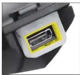
natural_image
Close-up of a black electronic component with a yellow highlighted connector (no visible text or symbols)C€0560
Made in Philippines
Model: BTMOTOFS
FCC ID: QVNBTMOTOF5
IC:7717A-BTMOTOFS
INTERPHONE, complies with CEI EN 60529/1997
The Bluetooth ^TM word mark and logos
are registered trademarks owned
by Bluetooth SIG, Inc. and any use of
such marks is under license.
COMPANY WITH QUALITY MANAGEMENT
SISTEN CERTIFIED BY DNV = ISO 9001:2008 =
CELLULAR ITALIA S.P.A.
www.cellularline.com
www.interphone.cellularline.com