
X299E-ITX/ac - Motherboard ASROCK - Free user manual and instructions
Find the device manual for free X299E-ITX/ac ASROCK in PDF.

| Product Type | Motherboard |
| Brand | ASRock |
| Model | X299E-ITX/ac |
| Form Factor | Mini-ITX (17 cm x 17 cm) |
| Approximate Weight | 500 g |
| CPU Socket | LGA 2066 |
| Chipset | Intel® X299 |
| Memory Type | DDR4 SO-DIMM, up to 64 GB, quad-channel |
| Memory Slots | 4 x DDR4 SO-DIMM |
| Supported Memory Frequency | DDR4 4000(OC) / 3866(OC) / 3800(OC) / 3733(OC) / 3600(OC) / 3200(OC) / 2933(OC) / 2800(OC) / 2666 / 2400 / 2133 |
| Expansion Slot | 1 x PCI Express 3.0 x16 |
| Storage | 6 x SATA3 6 Gbps, 3 x Ultra M.2 (PCIe Gen3 x4 / SATA) |
| Audio | 7.1 CH HD (Realtek ALC1220), Purity Sound™ 4 |
| Network | 2 x Gigabit LAN (Intel® I219V and I211AT), Wi-Fi 802.11ac + Bluetooth 4.2 |
| Rear USB Ports | 1 x USB 3.1 Gen2 Type-A, 1 x USB 3.1 Gen2 Type-C, 4 x USB 3.1 Gen1 |
| Power | 1 x ATX 24-pin, 1 x 12V 8-pin |
| Compatible Operating System | Microsoft® Windows® 10 64-bit |
| Main Features | Intel® Turbo Boost Max 3.0 support, Hyper BCLK III, UEFI BIOS, RGB LED, Virtual RAID on CPU |
| Maintenance & Cleaning | Regular dusting, avoid moisture, use a soft cloth |
| Safety | Overvoltage protection, electrostatic discharge, lightning |
| Spare Parts & Repairability | Wi-Fi antenna, SATA cables, M.2 screws (optional) |
| Warranty | Check ASRock website for terms |
Frequently Asked Questions - X299E-ITX/ac ASROCK
User questions about X299E-ITX/ac ASROCK
0 question about this device. Answer the ones you know or ask your own.
Ask a new question about this device
Download the instructions for your Motherboard in PDF format for free! Find your manual X299E-ITX/ac - ASROCK and take your electronic device back in hand. On this page are published all the documents necessary for the use of your device. X299E-ITX/ac by ASROCK.
USER MANUAL X299E-ITX/ac ASROCK
Published October 2017
Copyright©2017 ASRock INC. All rights reserved.
Copyright Notice:
No part of this documentation may be reproduced, transcribed, transmitted, or translated in any language, in any form or by any means, except duplication of documentation by the purchaser for backup purpose, without written consent of ASRock Inc.
Products and corporate names appearing in this documentation may or may not be registered trademarks or copyrights of their respective companies, and are used only for identification or explanation and to the owners' benefit, without intent to infringe.
Disclaimer:
Specifications and information contained in this documentation are furnished for informational use only and subject to change without notice, and should not be constructed as a commitment by ASRock. ASRock assumes no responsibility for any errors or omissions that may appear in this documentation.
With respect to the contents of this documentation, ASRock does not provide warranty of any kind, either expressed or implied, including but not limited to the implied warranties or conditions of merchantability or fitness for a particular purpose.
In no event shall ASRock, its directors, officers, employees, or agents be liable for any indirect, special, incidental, or consequential damages (including damages for loss of profits, loss of business, loss of data, interruption of business and the like), even if ASRock has been advised of the possibility of such damages arising from any defect or error in the documentation or product.

This device complies with Part 15 of the FCC Rules. Operation is subject to the following two conditions:
(1) this device may not cause harmful interference, and
(2) this device must accept any interference received, including interference that may cause undesired operation.
CALIFORNIA, USA ONLY
The Lithium battery adopted on this motherboard contains Perchlorate, a toxic substance controlled in Perchlorate Best Management Practices (BMP) regulations passed by the California Legislature. When you discard the Lithium battery in California, USA, please follow the related regulations in advance.
"Perchlorate Material-special handling may apply, see www.dtsc.ca.gov/hazardouswaste/perchlorate"
ASRock Website: http://www.asrock.com

AUSTRALIA ONLY
Our goods come with guarantees that cannot be excluded under the Australian Consumer Law. You are entitled to a replacement or refund for a major failure and compensation for any other reasonably foreseeable loss or damage caused by our goods. You are also entitled to have the goods repaired or replaced if the goods fail to be of acceptable quality and the failure does not amount to a major failure. If you require assistance please call ASRock Tel : +886-2-28965588 ext.123 (Standard International call charges apply)
Manufactured under license under U.S. Patent Nos: 5,956,674; 5,974,380; 6,487,535; 7,003,467 & other U.S. and worldwide patents issued & pending. DTS, the Symbol, & DTS and the Symbol together is a registered trademark & DTS Connect, DTS Interactive, DTS Neo:PC are trademarks of DTS, Inc. Product includes software.
© DTS, Inc., All Rights Reserved.

Connect

Interactive

Neo:PC
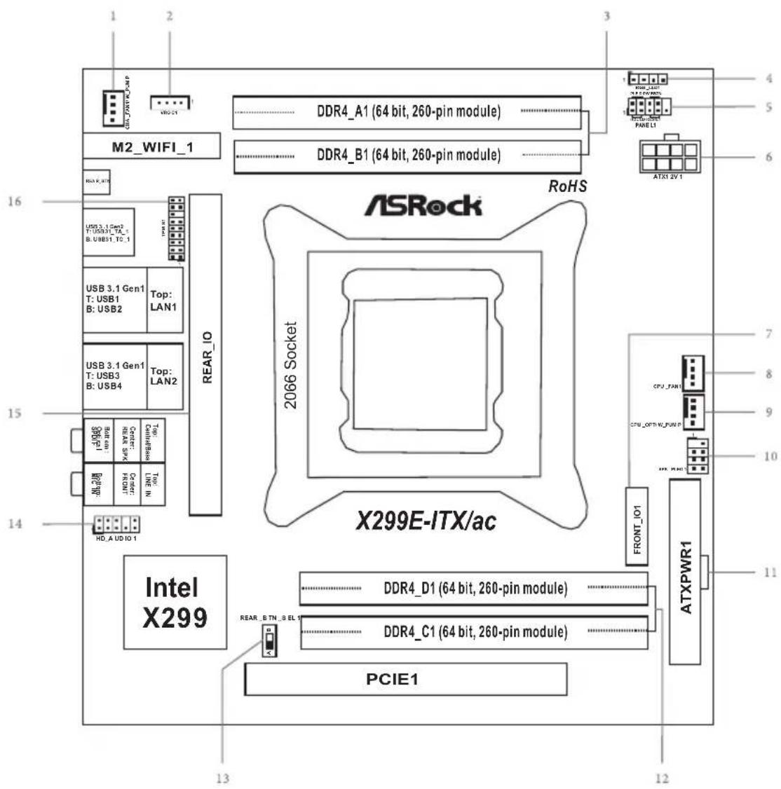
Motherboard Layout
Top Side View
text_image
1 2 3 4 M2_WIFI_1 DDR4_A1 (64 bit, 260-pin module) DDR4_B1 (64 bit, 260-pin module) DDR4_SAT M2_WIFI_1 DDR4_SAT DDR4_SAT DDR4_SAT DDR4_SAT DDR4_SAT DDR4_SAT DDR4_SAT DDR4_SAT DDR4_SAT DDR4_SAT DDR4_SAT DDR4_SAT DDR4_SAT DDR4_SAT DDR4_SAT DDR4_SAT DDR4_SAT DDR4_SAT DDR4_SAT DDR4_SAT DDR4_SCAT DDR4_SCAT DDR4_SCAT DDR4_SCAT DDR4_SCAT DDR4_SCAT DDR4_SCAT DDR4_SCAT DDR4_SCAT DDR4_SCAT DDR4_SCAT DDR4_SCAT DDR4_SCAT DDR4_SCAT DDR4_SCAT DDR4_SCAT DDR4_SCAT DDR4_SCAT DDR4_SCAT DDR4_SCAT DDR4_SAT DDR4_SAT DDR4_SAT DDR4_SAT DDR4_SAT DDR4_SAT DDR4_SAT DDR4_SAT DDR4_SAT DDR4_SAT DDR4_SAT DDR4_SAT DDR4_SAT DDR4_SAT DDR4_SAT DDR4_SAT DDR4_SAT DDR4_SAT DDR4_SAT DDR4_S1 DDR4_D1 (64 bit, 260-pin module) DDR4_C1 (64 bit, 260-pin module) DDR4_D1 (64 bit, 260-pin module) DDR4_D1 (64 bit, 260-pin module) DDR4_D1 (64 bit, 260-pin module) DDR4_D1 (64 bit, 260-pin module) DDR4_D1 (64 bit, 260-pin module) DDR4_D1 (64 bit, 260-pin module) DDR4_D1 (63 bit, 259-bit) DDR4_D1 (63 bit, 259-bit) DDR4_D1 (63 bit, 259-bit) DDR4_D1 (63 bit, 259-bit) DDR4_D1 (63 bit, 259-bit) DDR4_D1 (63 bit, 259-bit) DDR4_D1 (63 bit, 259-bit) DDR4_D1 (63 bit, 260-pin module) DDR4_D1 (63 bit, 260-pin module) DDR4_D1 (63 bit, 260-pin module) DDR4_D1 (63 bit, 260-pin module) DDR4_D1 (63 bit, 260-pin module) DDR4_D1 (63 bit, 260-pin module) DDR4_D1 (63 bit, 260-pin module) DDR4_D1 (63 bit, 260-pin module) DDR4_D1 (63 bit, 260-pin module) DDR4_D1 (63 bit, 260-pin module) DDR4_D1 (63 bit, 260-pin module) DDR4_D1 (63 bit, 260-pin module) DDR4_D1 (63 bit, 260-pin module) DDR4_D1 (63 bit, 260-pin module) DDR4_DI (63 bit, 260-pin module) DDR4_DI (63 bit, 260-pin module) DDR4_DI (63 bit, 260-pin module) DDR4_DI (63 bit, 260-pin module) DDR4_DI (63 bit, 260-pin module) DDR4_DI (63 bit, 260-pin module) DDR4_DI (63 bit, 260-pin model) DDR4_DI (63 bit, 260-pin model) DDR4_DI (63 bit, 260-pin model) DDR4_DI (63 bit, 260-pin model) DDR4_DI (63 bit, 260-pin model) DDR4_DI (63 bit, 260-pin model) DDR4_DI (63 bit, 260-pin model) DDR4_DI (63 bit, 259-bit) DDR4_DI (63 bit, 259-bit) DDR4_DI (63 bit, 259-bit) DDR4_DI (63 bit, 259-bit) DDR4_DI (63 bit, 259-bit) DDR4_DI (63 bit, 259-bit) DDR4_DI (63 bit, 259-bit) DDR4_DI (63 bit, 259-bit) DDR4_DI (63 bit, 259-bit) DDR4_DI (63 bit, 259-bit) DDR4_DI (63 bit, 259-bit) DDR4_DI (63 bit, 259-bit) DDR4_DI (63 bit, 259-bit) DDR4_DI (63 bit, 259-bit) DDR4_DI (63 bit, 278-bit) DDR4_DI (63 bit, 278-bit) DDR4_DI (63 bit, 278-bit) DDR4_DI (63 bit, 278-bit) DDR4_DI (63 bit, 278-bit) DDR4_DI (63 bit, 278-bit) DDR4_DI (63 bit, 278-bit) DDR4_DI (63 bit, 278-bit)Back Side View
text_image
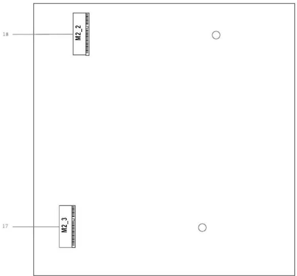
M2_2 18 M2_3 17Rear Card (For Rear Socket)

text_image
X299E-ITX REAR ASRock CT11CT12CT13CT14 RoHS M2_1 19Front Card (For Front Socket)
text_image
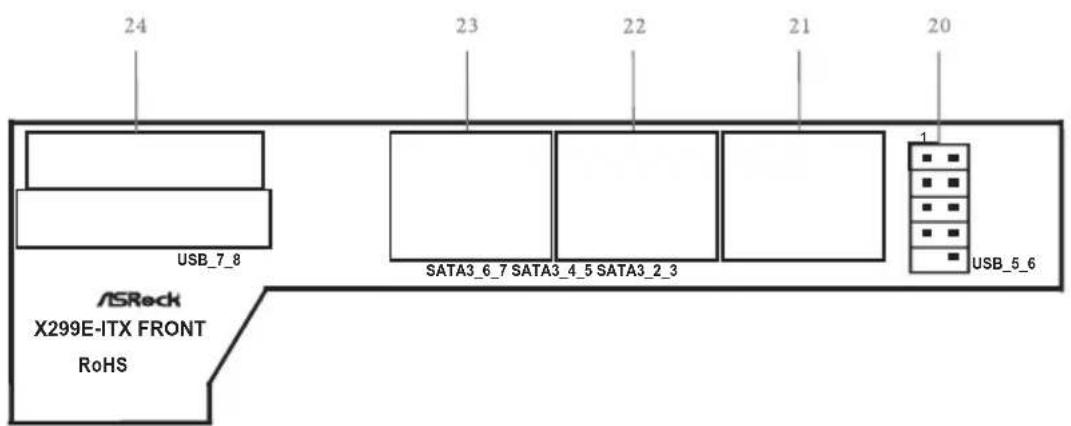
24 23 22 21 20 USB_7_8 SATA3_6_7 SATA3_4_5 SATA3_2_3 1 USB_5_6 ASReck X299E-ITX FRONT RoHSNo. Description
1 Chassis Fan / Waterpump Fan Connector (CHA_FAN1/W_PUMP)
2 Virtual RAID On CPU Header (VROC1)
3 2 x 260-pin DDR4 SO-DIMM Slots (DDR4_A1, DDR4_B1)
4 RGB LED Header (RGB_LED1)
5 System Panel Header (PANEL1)
6 ATX 12V Power Connector (ATX12V1)
7 Front Socket (FRONTI_IO1)
8 CPU Fan Connector (CPU_FAN1)
9 CPU Fan / Waterpump Fan Connector (CPU_OPT/W_PUMP)
10 Power LED and Speaker Header (SPK_PLED1)
11 ATX Power Connector (ATXPWR1)
12 2 x 260-pin DDR4 SO-DIMM Slots (DDR4_C1, DDR4_D1)
13 Rear Button Switch (REAR_BTN_SEL1)
14 Front Panel Audio Header (HD_AUDIO1)
15 Rear Socket (REAR_IO)
16 TPM Header (TPMS1)
17 Ultra M.2 Socket (M2_3)
18 Ultra M.2 Socket (M2_2)
19 Ultra M.2 Socket (M2_1)
20 USB 2.0 Header (USB_5_6)
21 SATA3 Connectors (SATA3_2_3)
22 SATA3 Connectors (SATA3_4_5)
23 SATA3 Connectors (SATA3_6_7)
24 USB 3.1 Gen1 Header (USB_7_8)
I/O Panel
text_image
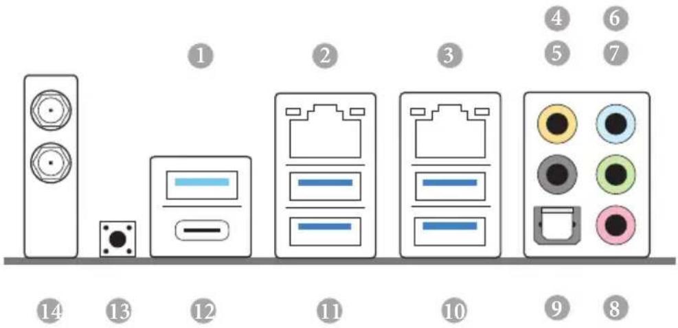
Diagram showing a sequence of electronic devices with numbered labels from 1 to 14, including speaker, ports, and buttons.No. Description No. Description
1 USB 3.1 Gen2 Type-A Port (USB31_TA_1) 8 Microphone (Pink)
2 LAN RJ-45 Port (Intel® I211AT)* 9 Optical SPDIF Out Port
3 LAN RJ-45 Port (Intel® I219V)* 10 USB 3.1 Gen1 Ports (USB_34)
4 Central / Bass (Orange) 11 USB 3.1 Gen1 Ports (USB_12)
5 Rear Speaker (Black) 12 USB 3.1 Gen2 Type-C Port (USB31_TC_1)
6 Line In (Light Blue) 13 Clear CMOS Button / Power Button***
7 Front Speaker (Lime)** 14 Antenna Ports
* There are two LEDs on each LAN port. Please refer to the table below for the LAN port LED indications.
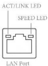
| Activity / Link LED | Speed LED | ||
| Status | Description | Status | Description |
| Off | No Link | Off | 10Mbps connection |
| Blinking | Data Activity | Orange | 100Mbps connection |
| On | Link | Green | 1Gbps connection |
** If you use a 2-channel speaker, please connect the speaker's plug into "Front Speaker Jack". See the table below for connection details in accordance with the type of speaker you use.
| Audio Output Channels | Front Speaker (No. 7) | Rear Speaker (No. 5) | Central / Bass (No. 4) | Line In (No. 6) |
| 2 V -- -- -- | ||||
| 4 V V -- -- | ||||
| 6 V V V -- | ||||
| 8 V V V V |

To enable Multi-Streaming, you need to connect a front panel audio cable to the front panel audio header. After restarting your computer, you will find the "Mixer" tool on your system. Please select "Mixer ToolBox" click "Enable playback multi-streaming", and click "ok". Choose "2CH", "4CH", "6CH", or "8CH" and then you are allowed to select "Realtek HDA Primary output" to use the Rear Speaker, Central/Bass, and Front Speaker, or select "Realtek HDA Audio 2nd output" to use the front panel audio.
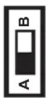
*** Use the Rear Button Switch to adjust the function of this switch.
A: Clear CMOS Button (default); B: Power Button.
Intel® Dual Band Wireless-AC 8265 (AC Wave 2 + BLE BT4.2) and ASRock WiFi 2.4/5 GHz Antenna
WiFi-802.11ac + BT Module
This motherboard comes with an exclusive WiFi 802.11 a/b/g/n/ac + BT v4.2 module (pre-installed on the rear I/O panel) that offers support for WiFi 802.11 a/b/g/n/ac connectivity standards and Bluetooth v4.2. WiFi + BT module is an easy-to-use wireless local area network (WLAN) adapter to support WiFi + BT. Bluetooth v4.2 standard features Smart Ready technology that adds a whole new class of functionality into the mobile devices. BT 4.2 also includes Low Energy Technology and ensures extraordinary low power consumption for PCs. The 2T2R WiFi solution sets a WiFi high speed standard and offers max link rate up to 867Mbps.
* The transmission speed may vary according to the environment.

natural_image
Black square device with diagonal stripe and attached cable, no visible text or symbols on the device itselfASRock WiFi 2.4/5 GHz Antenna
Chapter 1 Introduction
Thank you for purchasing ASRock X299E-ITX/ac motherboard, a reliable motherboard produced under ASRock's consistently stringent quality control. It delivers excellent performance with robust design conforming to ASRock's commitment to quality and endurance.

Because the motherboard specifications and the BIOS software might be updated, the content of this documentation will be subject to change without notice. In case any modifications of this documentation occur, the updated version will be available on ASRock's website without further notice. If you require technical support related to this motherboard, please visit our website for specific information about the model you are using. You may find the latest VGA cards and CPU support list on ASRock's website as well. ASRock website http://www.asrock.com.
1.1 Package Contents
• ASRock X299E-ITX/ac Motherboard (Mini-ITX Form Factor)
• ASRock X299E-ITX/ac Quick Installation Guide
• ASRock X299E-ITX/ac Support CD
- 1 x I/O Panel Shield
• 2 x Serial ATA (SATA) Data Cables (Optional)
• 1 x ASRock WiFi 2.4/5 GHz Antenna (Optional)
- 3 x Screws for Ultra M.2 Sockets (Optional)
1.2 Specifications
Platform
- Mini-ITX Form Factor
- 10 Layer PCB
CPU
- Supports Intel ^TM Core X-Series Processor Family (79xx, 78xx Series) for the LGA 2066 Socket
* Supports 28 and 44 PCIe lane processors (6-core and above) only. 16 PCIe lane processors (4-core) are not supported. Please refer to CPU Support List on ASRock's website for more information. (http://www.asrock.com/) - Digi Power design
• 7 Power Phase design
• Supports Intel® Turbo Boost Max Technology 3.0
• Supports ASRock Hyper BCLK Engine III
Chipset
- Intel® X299
Memory
• Quad Channel DDR4 Memory Technology
• 4 x DDR4 SO-DIMM Slots
- Supports DDR4 4000+(OC)*/3866(OC)/3800(OC)/3733(OC)/3600(OC)/3200(OC)/2933(OC)/2800
(OC)/2666/2400/2133 non-ECC, un-buffered memory
* The maximum memory frequency supported may vary by processor type.
* Please refer to Memory Support List on ASRock's website for more information. (http://www.asrock.com/)
• Max. capacity of system memory: 64GB
• Supports Intel ^® Extreme Memory Profile (XMP) 2.0
Expansion
• 1 x PCI Express 3.0 x16 Slot (PCIE1: x16 mode)
- 1 x Vertical M.2 Socket (Key E) with the bundled WiFi-802.11ac module (on the rear I/O)
• 15μ Gold Contact in VGA PCIe Slot (PCIE1)
Audio
- 7.1 CH HD Audio with Content Protection (Realtek ALC1220 Audio Codec)
• Premium Blu-ray Audio support
• Supports Surge Protection
• Supports Purity Sound ^TM 4
- Nichicon Fine Gold Series Audio Caps
- 120dB SNR DAC with Differential Amplifier
- NE5532 Premium Headset Amplifier for Front Panel Audio Connector (Supports up to 600 Ohm headsets)
- Pure Power-In
- Direct Drive Technology
- Impedance Sensing on Front Out port
- Gold Audio Jacks
- 15 μ Gold Audio Connector
• Supports DTS Connect
LAN
• Gigabit LAN 10/100/1000 Mb/s
• 1 x Giga PHY Intel® I219V, 1 x GigaLAN Intel® I211AT
• Supports Wake-On-LAN
• Supports Lightning/ESD Protection
• Supports Energy Efficient Ethernet 802.3az
- Supports PXE
Wireless
- Intel® Dual Band Wireless-AC 8265
• Supports IEEE 802.11a/b/g/n/ac - Supports Dual-Band (2.4/5 GHz with 80Mhz bandwidth and MU-MIMO)
• Supports high speed wireless connections up to 867Mbps - 2 antennas to support 2 (Transmit) x 2 (Receive) diversity technology
• Supports Bluetooth 4.2 / 3.0 + High speed class II
Rear Panel
- 2 x Antenna Ports
• 1 x Optical SPDIF Out Port - 1 x USB 3.1 Gen2 Type-A Port (10 Gb/s) (ASMedia ASM3142) (Supports ESD Protection)
- 1 x USB 3.1 Gen2 Type-C Port (10 Gb/s) (ASMedia ASM3142) (Supports ESD Protection)
- 4 x USB 3.1 Gen1 Ports (ASMedia ASM1074 Hub) (Supports ESD Protection)*
- 2 x RJ-45 LAN Ports with LED (ACT/LINK LED and SPEED LED)*
* If you remove X299E-ITX REAR card, USB 3.1 Gen1 ports and RJ-45 LAN Ports will not work.
• 1 x Clear CMOS Button / Power Button
- HD Audio Jacks: Rear Speaker / Central / Bass / Line in / Front Speaker / Microphone (Gold Audio Jacks)
Storage
- 6 x SATA3 6.0 Gb/s Connectors, support RAID (RAID 0, RAID 1, RAID 5, RAID 10, Intel Rapid Storage Technology 15 and Intel Smart Response Technology), NCQ, AHCI and Hot Plug*
- 1 x Ultra M.2 Socket (M2_1), supports M Key type 2230/2242/2260/2280 M.2 SATA3 6.0 Gb/s module and M.2 PCI Express module up to Gen3 x4 (32 Gb/s) ^**
- 2 x Ultra M.2 Sockets (M2_2 and M2_3), support M Key type 2280 M.2 PCI Express module up to Gen3 x4 (32 Gb/s)**
** Supports Intel® Optane™ Technology (M2_1)
** Supports NVMe SSD as boot disks
** Supports Virtual RAID On CPU (M2_2 and M2_3)
Connector
• 1 x Virtual RAID On CPU Header
- 1 x TPM Header
• 1 x Power LED and Speaker Header
- 1 x RGB LED Header
* Supports in total up to 12V/3A, 36W LED Strip
• 1 x CPU Fan Connector (4-pin)
* The CPU Fan Connector supports the CPU fan of maximum 1A (12W) fan power.
- 1 x CPU Optional/Water Pump Fan Connector (4-pin) (Smart Fan Speed Control)
* The CPU Optional/Water Pump Fan supports the water cooler fan of maximum 1.5A (18W) fan power.
- 1 x Chassis Fan Connector (4-pin) (Smart Fan Speed Control)
* CPU_OPT/W_PUMP and CHA_FAN1 can auto detect if 3-pin or 4-pin fan is in use.
- 1 x 24 pin ATX Power Connector (Hi-Density Power Connector)
- 1 x 8 pin 12V Power Connector (Hi-Density Power Connector)
- 1 x Front Panel Audio Connector (15μ Gold Audio Connector)
| 1 x USB 2.0 Header (Supports 2 USB 2.0 ports) (Supports ESD Protection)1 x USB 3.1 Gen1 Header (Supports 2 USB 3.1 Gen1 ports) (Supports ESD Protection)1 x Rear Button (A: Clear CMOS Button; B: Power Button) | |
| BIOS Feature | AMI UEFI Legal BIOS with multilingual GUI supportACPI 6.1 Compliant wake up eventsSMBIOS 3.0 SupportCPU, DRAM, PCH 1.0V, VCCIO,VCCSA,Voltage Multi-adjustment |
| Hardware Monitor | Temperature Sensing: CPU, CPU Optional/Water Pump, Chassis FansFan Tachometer: CPU, CPU Optional/Water Pump, Chassis FansQuiet Fan (Auto adjust chassis fan speed by CPU temperature): CPU, CPU Optional/Water Pump, Chassis FansFan Multi-Speed Control: CPU, CPU Optional/Water Pump, Chassis FansVoltage monitoring: +12V, +5V, +3.3V, CPU Vcore, DRAM, PCH 1.0V, VCCIO, VCCSA |
| OS | Microsoft® Windows® 10 64-bit |
| Certifications | FCC, CE, WHQLErP/EuP ready (ErP/EuP ready power supply is required) |
* For detailed product information, please visit our website: http://www.asrock.com

Please realize that there is a certain risk involved with overclocking, including adjusting the setting in the BIOS, applying Untied Overclocking Technology, or using third-party overclocking tools. Overclocking may affect your system's stability, or even cause damage to the components and devices of your system. It should be done at your own risk and expense. We are not responsible for possible damage caused by overclocking.
Chapter 2 Installation
This is a Mini-ITX form factor motherboard. Before you install the motherboard, study the configuration of your chassis to ensure that the motherboard fits into it.
Pre-installation Precautions
Take note of the following precautions before you install motherboard components or change any motherboard settings.
- Make sure to unplug the power cord before installing or removing the motherboard components. Failure to do so may cause physical injuries and damages to motherboard components.
- In order to avoid damage from static electricity to the motherboard's components, NEVER place your motherboard directly on a carpet. Also remember to use a grounded wrist strap or touch a safety grounded object before you handle the components.
- Hold components by the edges and do not touch the ICs.
- Whenever you uninstall any components, place them on a grounded anti-static pad or in the bag that comes with the components.
- When placing screws to secure the motherboard to the chassis, please do not over-tighten the screws! Doing so may damage the motherboard.
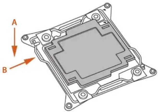
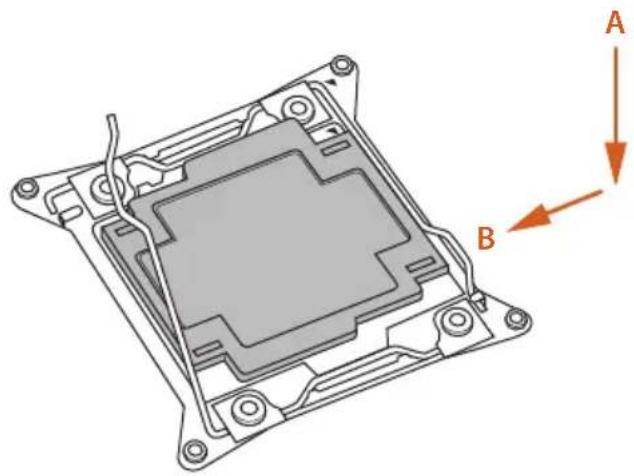
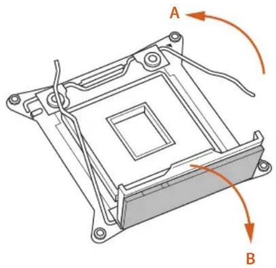
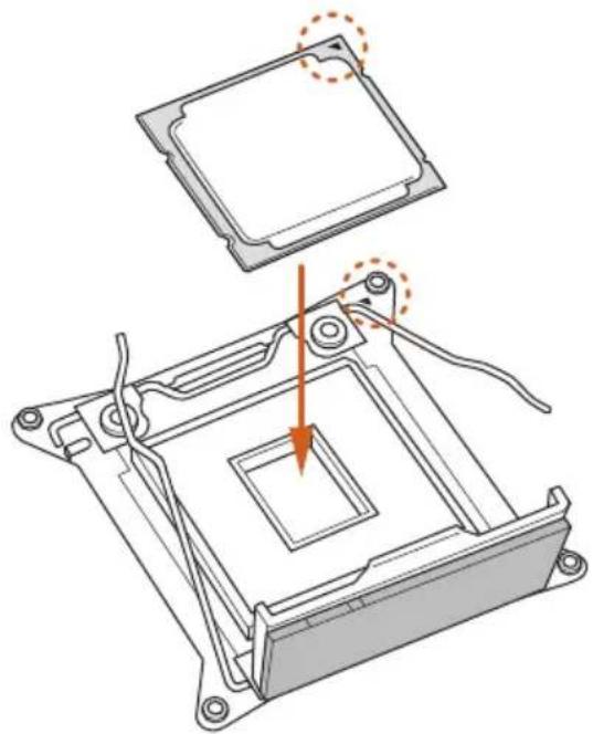
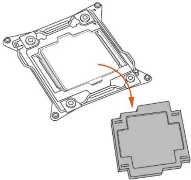
2.1 Installing the CPU

- Before you insert the 2066-Pin CPU into the socket, please check if the PnP cap is on the socket, if the CPU surface is unclean, or if there are any bent pins in the socket. Do not force to insert the CPU into the socket if above situation is found. Otherwise, the CPU will be seriously damaged.
- Unplug all power cables before installing the CPU.
CAUTION:
Please note that X299 platform is only compatible with the LGA 2066 socket, which is incompatible with the LGA 2011-3 socket (for X99 platform).
1
natural_image
3D technical diagram of a mechanical component with labeled arrows A and B indicating orientation (no text or symbols beyond labels)2
natural_image
Technical diagram of a mechanical component with labeled parts A and B, showing internal structure and mounting holes (no text or symbols beyond labels)3
natural_image
Technical line drawing of a mechanical component with labeled points A and B, showing internal structure and mounting brackets (no text or symbols beyond labels)4
natural_image
Technical diagram of a mechanical assembly with an open component and a highlighted section, showing no text or symbols.5
natural_image
Technical diagram of a mechanical component with highlighted internal structure and orange arrows indicating motion (no text or symbols)6
natural_image
Technical line drawing of a mechanical component with labeled points A and B (no text or symbols beyond labels)7
natural_image
Technical diagram of a mechanical component with labeled parts A and B, showing internal structure and mounting holes (no text or symbols beyond labels)8
natural_image
Technical illustration of a mechanical component with an arrow indicating assembly or transformation (no text or symbols present)
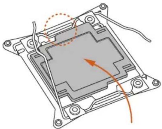
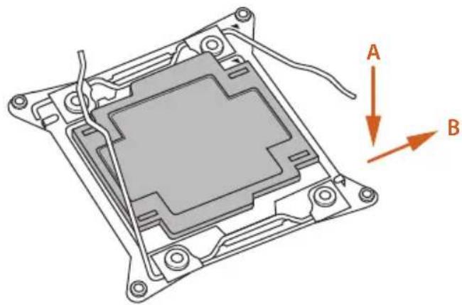
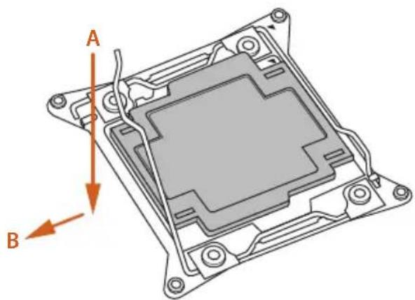
Please save and replace the cover if the processor is removed. The cover must be placed if you wish to return the motherboard for after service.
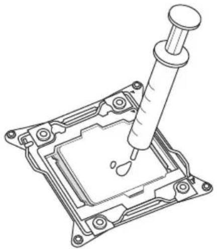
2.2 Installing the CPU Fan and Heatsink
natural_image
Technical line drawing of a mechanical assembly with a pipette inserted into a component (no text or symbols)1

natural_image
Technical diagram showing a CPU fan and its internal components with mounting holes (no text or labels)2
text_image
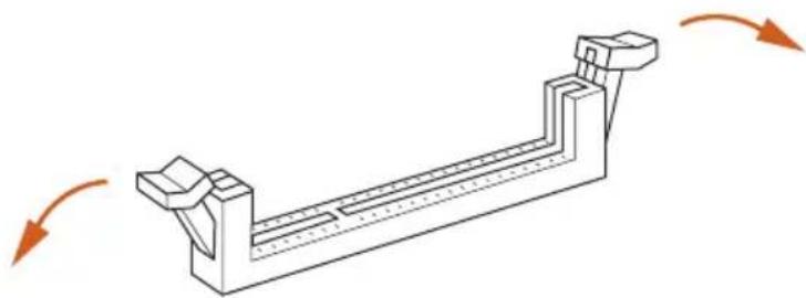
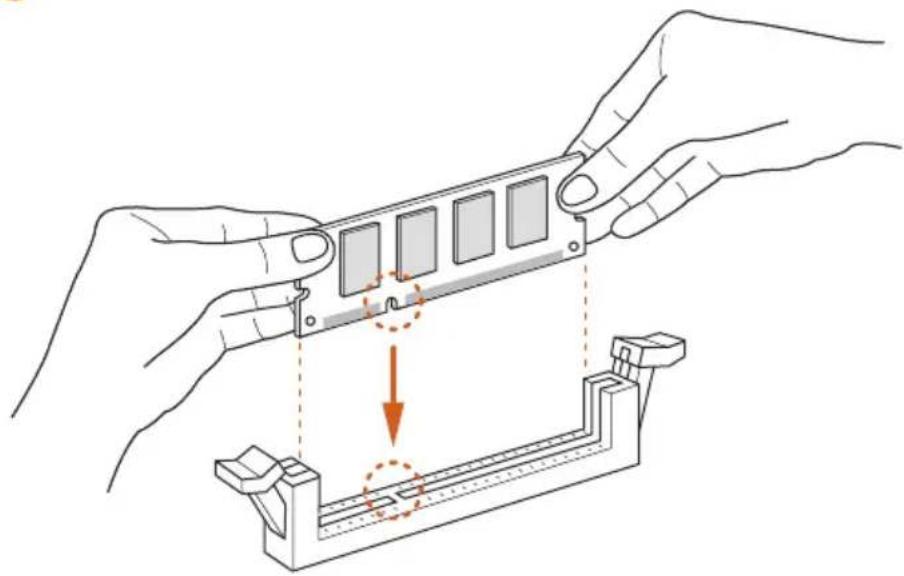
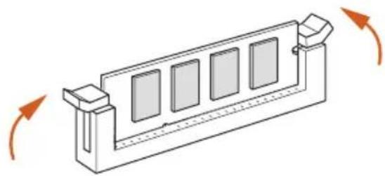
GND3412.3 Installation of Memory Modules (SO-DIMM)
This motherboard provides four 260-pin DDR4 (Double Data Rate 4) SO-DIMM slots, and supports Quad Channel Memory Technology.

- For quad channel configuration, you always need to install identical (the same brand, speed, size and chip-type) DDR4 SO-DIMM pairs.
- It is not allowed to install a DDR, DDR2 or DDR3 memory module into a DDR4 slot; otherwise, this motherboard and SO-DIMM may be damaged.
- The SO-DIMM only fits in one correct orientation. It will cause permanent damage to the motherboard and the SO-DIMM if you force the SO-DIMM into the slot at incorrect orientation.
Quad Channel Memory Configuration
DDR4_A1
Populated
DDR4_B1
Populated
DDR4_D1
Populated
DDR4_C1
Populated
- If only two memory modules are installed in the DDR4 SO-DIMM slots, then Dual Channel Memory Technology is activated. If three memory modules are installed, then Triple Channel Memory Technology is activated.
1
natural_image
Isometric line drawing of a mechanical component with arrows indicating motion direction (no text or symbols)2
natural_image
Illustration of hands assembling a mechanical component with a highlighted section (no text or symbols)3
natural_image
Technical line drawing of a mechanical component with four rectangular slots and directional arrows indicating rotation (no text or symbols)2.4 Expansion Slot (PCI Express Slot)
There is 1 PCI Express slot on the motherboard.

Before installing an expansion card, please make sure that the power supply is switched off or the power cord is unplugged. Please read the documentation of the expansion card and make necessary hardware settings for the card before you start the installation.
PCIe slot:
PCIE1 (PCIe 3.0 x16 slot) is used for PCI Express x16 lane width graphics cards.
2.5 Onboard Headers and Connectors

Onboard headers and connectors are NOT jumpers. Do NOT place jumper caps over these headers and connectors. Placing jumper caps over the headers and connectors will cause permanent damage to the motherboard.
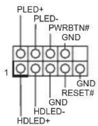
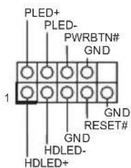
System Panel Header (9-pin PANEL1) (see p.1, No. 5)
text_image
PLED+ PLED- PWRBTN# GND 1 GND RESET# GND HDLED- HDLED+Connect the power switch, reset switch and system status indicator on the chassis to this header according to the pin assignments below. Note the positive and negative pins before connecting the cables.

PWRBTN (Power Switch):
Connect to the power switch on the chassis front panel. You may configure the way to turn off your system using the power switch.
RESET (Reset Switch):
Connect to the reset switch on the chassis front panel. Press the reset switch to restart the computer if the computer freezes and fails to perform a normal restart.
PLED (System Power LED):
Connect to the power status indicator on the chassis front panel. The LED is on when the system is operating. The LED keeps blinking when the system is in S1/S3 sleep state. The LED is off when the system is in S4 sleep state or powered off (S5).
HDLED (Hard Drive Activity LED):
Connect to the hard drive activity LED on the chassis front panel. The LED is on when the hard drive is reading or writing data.
The front panel design may differ by chassis. A front panel module mainly consists of power switch, reset switch, power LED, hard drive activity LED, speaker and etc. When connecting your chassis front panel module to this header, make sure the wire assignments and the pin assignments are matched correctly.
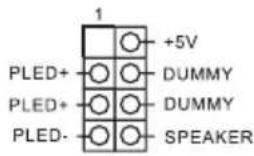
Power LED and Speaker Header
(7-pin SPK_PLED1)
(see p.1, No. 10)
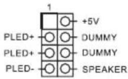
Please connect the chassis power LED and the chassis speaker to this header.
Serial ATA3 Connectors
(SATA3_2_3:
see p.3, No. 21)
(SATA3_4_5:
see p.3, No. 22)
(SATA3_6_7:
see p.3, No. 23)
SATA3_6_7 SATA3_4_5 SATA3_2_3
These six SATA3
connectors support SATA
data cables for internal
storage devices with up to
6.0 Gb/s data transfer rate.
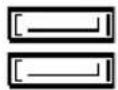
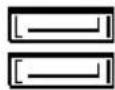
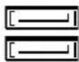
USB 2.0 Header
(9-pin USB_5_6)
(see p.3, No. 20)
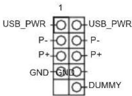
text_image
USB_PWR P- P+ GND USB_PWR P- P+ DUMMYThis USB 2.0 header can support two ports.
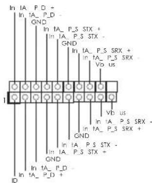
USB 3.1 Gen1 Header
(19-pin USB_7_8)
(see p.3, No. 24)
text_image
In IA_P_D - In IA_P_D - GND In ta_P_S STX + In IA_P_S STX - GND In ta_P_S SRX + In ta_P_S SRX - Vb us In ta_P_S SRX - GND In ta_P_S STX - In IA_P_S STX + GND In ta_P_D - IDThis USB 3.1 Gen1 header can support two ports.
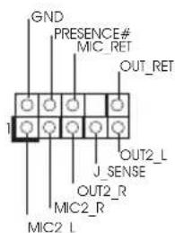
Front Panel Audio Header
(9-pin HD_AUDIO1)
(see p.1, No. 14)
text_image
GND PRESENCE# MIC_RET OUT_RET 1 J.SENSE OUT2_R MIC2_R MIC2_LThis header is for
connecting audio devices
to the front audio panel.

- High Definition Audio supports Jack Sensing, but the panel wire on the chassis must support HDA to function correctly. Please follow the instructions in our manual and chassis manual to install your system.
- If you use an AC'97 audio panel, please install it to the front panel audio header by the steps below:
A. Connect Mic_IN (MIC) to MIC2_L.
B. Connect Audio_R (RIN) to OUT2_R and Audio_L (LIN) to OUT2_L.
C. Connect Ground (GND) to Ground (GND).
D. MIC_RET and OUT_RET are for the HD audio panel only. You don't need to connect them for the AC'97 audio panel.
E. To activate the front mic, go to the "FrontMic" Tab in the Realtek Control panel and adjust "Recording Volume".
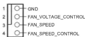
Chassis Optional/Water
Pump Fan Connector
(4-pin CHA_FAN1/W_PUMP)
(see p.1, No. 1)
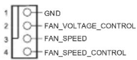
This motherboard provides a 4-Pin water cooling chassis fan connector. If you plan to connect a 3-Pin chassis water cooler fan, please connect it to Pin 1-3.
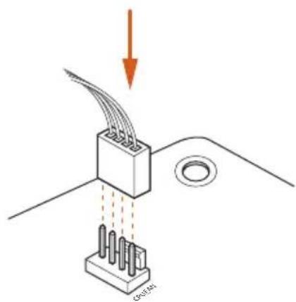
CPU Fan Connector
(4-pin CPU_FAN1)
(see p.1, No. 8)
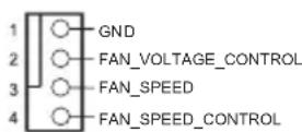
This motherboard provides a 4-Pin CPU fan (Quiet Fan) connector. If you plan to connect a 3-Pin CPU fan, please connect it to Pin 1-3.
CPU Optional/Water
Pump Fan Connector
(4-pin CPU_OPT/W_PUMP)
(see p.1, No. 9)
This motherboard provides a 4-Pin water cooling CPU fan connector. If you plan to connect a 3-Pin CPU water cooler fan, please connect it to Pin 1-3.
ATX Power Connector (24-pin ATXPWR1) (see p.1, No. 11)
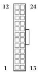
This motherboard provides a 24-pin ATX power connector. To use a 20-pin ATX power supply, please plug it along Pin 1 and Pin 13.
ATX 12V Power Connector (8-pin ATX12V1) (see p.1, No. 6)
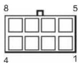
This motherboard provides a 8-pin ATX 12V power connector. To use a 4-pin ATX power supply, please plug it along Pin 1 and Pin 5.
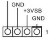
TPM Header (17-pin TPMS1) (see p.1, No. 16)
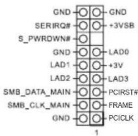
text_image
GND ○─○─GND SERIRQ#─○─+3VSB S_PWRDWN#─○─ GND ○─○─LAD0 LAD1 ○─○─+3V LAD2 ○─○─LAD3 SMB_DATA_MAIN─○─PCIRST# SMB_CLK_MAIN─○─FRAME GND ○─○─PCICLK 1This connector supports Trusted Platform Module (TPM) system, which can securely store keys, digital certificates, passwords, and data. A TPM system also helps enhance network security, protects digital identities, and ensures platform integrity.
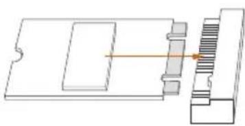
RGB LED Header (4-pin RGB_LED1) (see p.1, No. 4)
This RGB header is used to connect RGB LED extension cable which allows users to choose from various LED lighting effects.
Caution: Never install the RGB LED cable in the wrong orientation; otherwise, the cable may be damaged.
*Please refer to page 33 for further instructions on this header.
Virtual RAID On CPU
Header
(4-pin VROC1)
(see p.1, No. 2)
VROC RAID KEY
This connector supports Intel ^®
Virtual RAID on CPU and
NVME/AHCI RAID on CPU
PCIE.
With the introduction of the Intel VROC product, there are three modes of operation:
SKU HW key required Key features
Pass-thru Not needed
Standard Standard Key
Premium Premium Key
*For further details on VROC, please refer to the official information released by Intel.
2.6 Smart Switches
The motherboard has two smart switches: Rear Button Switch and Clear CMOS Button/Power Button.
Rear Button Switch
(REAR_BTN_SEL1)
(see p.1, No. 13)

Rear Button Switch allows
users to easily adjust the
function of the Clear
CMOS Button/Power
Button on the rear panel
I/O. A: Clear CMOS
Button (default); B: Power
Button
Clear CMOS Button/
Power Button
(REAR_BTN)
(see p.5, No. 13)
The function of this
button can be adjusted by the Rear Button Switch.
Clear CMOS Button
(default) allows users to quickly clear the CMOS
values. Power Button
allows users to quickly
turn on/off the system.

Clear CMOS is workable only when you power off your computer and unplug the power supply.
2.7 M.2\_SSD (NGFF) Module Installation Guide (M2\_1)
The M.2, also known as the Next Generation Form Factor (NGFF), is a small size and versatile card edge connector that aims to replace mPCIe and mSATA. The Ultra M.2 Socket (M2_1) supports SATA3 6.0 Gb/s module and M.2 PCI Express module up to Gen3 x4 (32 Gb/s).
Installing the M.2\_SSD (NGFF) Module
natural_image
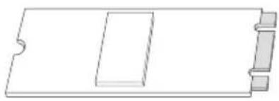
Pure technical line drawing of a rectangular component with cutouts and side brackets (no text or symbols)Step 1
Prepare a M.2_SSD (NGFF) module and the screw.
text_image
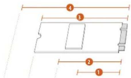
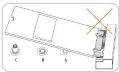
4 3 2 1Step 2
Depending on the PCB type and length of your M.2_SSD (NGFF) module, find the corresponding nut location to be used.
No.1234
| Nut Location A B C D | ||||
| PCB Length 3cm 4.2cm 6cm | 8cm | |||
| Module Type | Type2230 | Type 2242 | Type2260 | Type 2280 |


text_image
C B A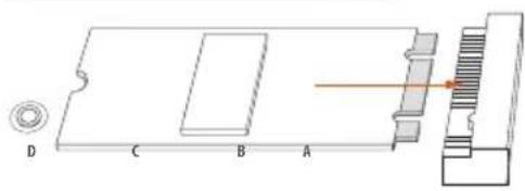
natural_image
Technical diagram of a mechanical assembly with labeled components A, B, C, D and an orange laser line (no text or symbols beyond labels)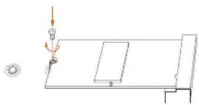
natural_image
Simple line drawing of a table with a lamp and a small inset showing a magnified view (no text or symbols)Step 3
Move the standoff based on the module type and length.
The standoff is placed at the nut location D by default. Skip Step 3 and 4 and go straight to Step 5 if you are going to use the default nut.
Otherwise, release the standoff by hand.
Step 4
Peel off the yellow protective film on the nut to be used. Hand tighten the standoff into the desired nut location on the motherboard.
Step 5
Align and gently insert the M.2 (NGFF) SSD module into the M.2 slot. Please be aware that the M.2 (NGFF) SSD module only fits in one orientation.
Step 6
Tighten the screw with a screwdriver to secure the module into place. Please do not overtighten the screw as this might damage the module.
M.2\_SSD (NGFF) Module Support List
Vendor Interface P/N
| ADATA SATA3 AXNS330E-32GM-B | |
| ADATA SATA3 AXNS381E-128GM-B | |
| ADATA SATA3 AXNS381E-256GM-B | |
| ADATA SATA3 ASU800NS38-256GT-C | |
| ADATA SATA3 ASU800NS38-512GT-C | |
| ADATA PCIe3 x4 ASX8000NP-256GM-C | |
| ADATA PCIe3 x4 ASX8000NP-512GM-C | |
| Crucial SATA3 CT120M500SSD4 | |
| Crucial SATA3 CT240M500SSD4 | |
| Kingston SATA3 SM2280S3 | |
| Kingston PCIe2 x4 SH2280S3/480G | |
| OCZ PCIe3 x4 RVD400 -M2280-512G (NVME) | |
| Plextor PCIe3 x4 PX-128M8PeG | |
| Plextor PCIe3 x4 PX-1TM8PeG | |
| Plextor PCIe3 x4 PX-256M8PeG | |
| Plextor PCIe3 x4 PX-512M8PeG | |
| Plextor PCIe PX-G256M6e | |
| Plextor PCIe PX-G512M6e | |
| Samsung PCIe3 x4 SM961 MZVPW128HEGM (NVM) | |
| Samsung PCIe3 x4 PM961 MZVLW128HEGR (NVME) | |
| Samsung PCIe3 x4 960 EVO (MZ-V6E250BW) (NVME) | |
| Samsung PCIe3 x4 960 EVO (MZ-V6E250) (NVME) | |
| Samsung PCIe3 x4 SM951 (MZHPV256HDGL) | |
| Samsung PCIe3 x4 SM951 (NVME) | |
| Samsung PCIe3 x4 SM951 (MZHPV512HDGL) | |
| Samsung PCIe3 x4 SM951 (NVME) | |
| Samsung PCIe x4 XP941-512G (MZHPU512HCGL) | |
| SanDisk PCIe SD6PP4M-128G | |
| SanDisk PCIe SD6PP4M-256G | |
| Team SATA3 TM4PS4128GMC105 | |
| Team SATA3 TM4PS4256GMC105 | |
| Team SATA3 TM8PS4128GMC105 | |
| Team SATA3 TM8PS4256GMC105 | |
| Transcend SATA3 TS256GMTS400 | |
| Transcend SATA3 TS512GMTS600 | |
| Transcend SATA3 TS512GMTS800 | |
| V-Color SATA3 VLM100-120G-2280B-RD | |
| V-Color SATA3 VLM100-240G-2280B-RD | |
| V-Color SATA3 VSM100-240G-2280 | |
| WD SATA3 WDS100T1B0B-00AS40 | |
| WD SATA3 WDS240G1G0B-00RC30 | |
| WD PCIe3 x4 WDS256G1X0C-00ENX0 (NVME) |
WD PCIe3 x4 WDS512G1X0C-00ENX0 (NVME)
For the latest updates of M.2_SSD (NFGG) module support list, please visit our website for details: http://www.asrock.com
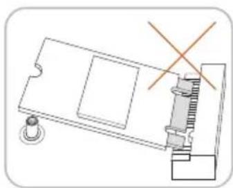
2.8 M.2\_SSD (NGFF) Module Installation Guide (M2\_2 and M2\_3)
The M.2, also known as the Next Generation Form Factor (NGFF), is a small size and versatile card edge connector that aims to replace mPCIe and mSATA. The Ultra M.2 Sockets (M2_2 and M2_3) support M.2 PCI Express module up to Gen3 x4 (32 Gb/s).
Installing the M.2\_SSD (NGFF) Module
natural_image
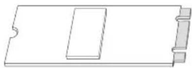
Pure technical line drawing of a rectangular component with cutouts and internal features (no text or symbols)Step 1
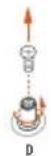
This motherboard supports M.2_ SSD (NGFF) module type 2280 only. Prepare a proper PCB lenth of module (8cm) and the screw.
natural_image
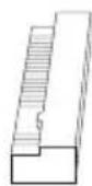
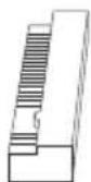
Technical line drawing of a mechanical assembly with no visible text or symbolsStep 2
Align and gently insert the M.2 (NGFF) SSD module into the M.2 slot. Please be aware that the M.2 (NGFF) SSD module only fits in one orientation.
natural_image
Pure mechanical assembly diagram showing a component with internal parts and an arrow indicating direction (no text or symbols)
natural_image
Simple line drawing of a mechanical setup with a lever and base plate (no text or symbols)Step 3
Tighten the screw with a screwdriver to secure the module into place. Please do not overtighten the screw as this might damage the module.
M.2\_SSD (NGFF) Module Support List
| Vendor Size Interface P/N |
| Intel 256GB PCIe3 x4 SSDPEKKF256G7 |
| Intel 512GB PCIe3 x4 SSDPEKKF512G7 |
| Kingston 480GB PCIe2 x4 SH2280S3/480G |
| OCZ 512GB PCIe3 x4 RVD400 -M2280-512G (NVME) |
| Plextor 128GB PCIe3 x4 PX-128M8PeG |
| Plextor 1TB PCIe3 x4 PX-1TM8PeG |
| Plextor 256GB PCIe3 x4 PX-256M8PeG |
| Plextor 256GB PCIe PX-G256M6e |
| Plextor 512GB PCIe3 x4 PX-512M8PeG |
| Plextor 512GB PCIe PX-G512M6e |
| Samsung 256GB PCIe3 x4 SM951 (MZHPV256HDGL) |
| Samsung 256GB PCIe3 x4 SM951 (NVME) |
| Samsung 512GB PCIe3 x4 SM951 (MZHPV512HDGL) |
| Samsung 512GB PCIe3 x4 SM951 (NVME) |
| Samsung 512GB PCIe x4 XP941-512G (MZHPU512HCGL) |
For the latest updates of M.2_SSD (NFGG) module support list, please visit our website for details: http://www.asrock.com
2.9 ASRock RGB LED
ASRock RGB LED is a lighting control utility specifically designed for unique individuals with sophisticated tastes to build their own stylish colorful lighting system. Simply by connecting the LED strip, you can customize various lighting schemes and patterns, including Static, Breathing, Strobe, Cycling, Music, Wave and more.
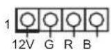
Connecting the LED Strip
Connect your RGB LED strips to the RGB LED Header (RGB_LED1) on the motherboard.
text_image
ASRock X299E-ITX/ac RGB_LED1 1 12V G R B 1 12V C P B
- Never install the RGB LED cable in the wrong orientation; otherwise, the cable may be damaged.
- Before installing or removing your RGB LED cable, please power off your system and unplug the power cord from the power supply. Failure to do so may cause damages to motherboard components.

- Please note that the RGB LED strips do not come with the package.
- The RGB LED header supports standard 5050 RGB LED strip (12V/G/R/B), with a maximum power rating of 3A (12V) and length within 2 meters.
ASRock RGB LED Utility
Now you can adjust the RGB LED color through the ASRock RGB LED utility. Download this utility from the ASRock Live Update & APP Shop and start coloring your PC style your way!
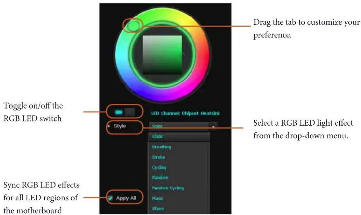
text_image
Drag the tab to customize your preference. Toggle on/off the RGB LED switch Style LED Channel: Chipset Heatsink Static Select a RGB LED light effect from the drop-down menu. Sync RGB LED effects for all LED regions of the motherboard Apply All1 Einleitung
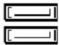
Serial-ATA-III-Anschlüsse
(SATA3_2_3:
siehe S. 3, Nr. 21)
(SATA3_4_5:
siehe S. 3, Nr. 22)
(SATA3_6_7:
siehe S. 3, Nr. 23)
SATA3_6_7 SATA3_4_5 SATA3_2_3


text_image
USB_PWR P- P+ GND USB_PWR P- P+ DUMMYtext_image
USB_PWR P- P+ GND USB_PWR P- P+ DUMMYtext_image
USB_PWR P- P+ GND USB_PWR P- P+ DUMMYtext_image
USB_PWR P- P+ GND USB_PWR P- P+ DUMMYnatural_image
Simple graphic with a magnifying glass icon and a horizontal line, no text or symbols present.1.1 パッケージの内容
1.2 仕様
| CPU | TM |
| (http://www.asrock.com/) |
TM
LAN
日本語
**
** Intel® Optane™

natural_image
Blank white image with no visible content, text, or symbols
natural_image
Blank white image with no visible content, text, or symbolsOS

natural_image
Blank white image with no visible content, text, or symbols
text_image
* http://www.asrock.com !日本語
1.3 オンボードのヘッダーとコネクタ

text_image
PLED+ PLED- PWRBTN# GND 1 GND RESET# GND HDLED- HDLED+
(Voltage Multi-adjustment)
硬件监控
CPU 可选 / 水泵、机箱风扇
1.0V、VCCIO、VCCSA
操作系统
认证
text_image
USB_PWR P- P+ GND USB_PWR P- P+ DUMMYAHCI RAID on CPU PCIE °
If you need to contact ASRock or want to know more about ASRock, you're welcome to visit ASRock's website at http://www.asrock.com; or you may contact your dealer for further information. For technical questions, please submit a support request form at http://www.asrock.com/support/tsd.asp
ASRock Incorporation
2F., No.37, Sec. 2, Jhongyang S. Rd., Beitou District,
Taipei City 112, Taiwan (R.O.C.)
ASRock EUROPE B.V.
Bijsterhuizen 11-11
6546 AR Nijmegen
The Netherlands
Phone: +31-24-345-44-33
Fax: +31-24-345-44-38
ASRock America, Inc.
13848 Magnolia Ave, Chino, CA91710
U.S.A.
Phone: +1-909-590-8308
Fax: +1-909-590-1026
For the following equipment:
Motherboard
| (Product Name) |
| X299E-ITX/ac / ASRock |
(Model Designation / Trade Name)
| ASRock Incorporation |
| (Manufacturer Name) |
2F., No.37, Sec. 2, Jhongyang S. Rd., Beitou District, Taipei City 112, Taiwan (R.O.C.)
| (Manufacturer Address) |
| is herewith confirmed to comply with the requirements set out in the Council Directive on the Approximation of the Laws of the Member States relating to Electromagnetic Compatibility Directive (2004/108/EC) and Safety Directive (2006/95/EC), the following standards are applied: |
EN 55022: 2006+A1:2007
EN 61000-3-2: 2009
EN 61000-3-3:2008
EN 55024: 1998 + A1:2001 + A2:2003
IEC 61000-4-2: 2008;
IEC 61000-4-3: 2010; IEC 61000-4-4: 2010;
IEC 61000-4-5: 2005; IEC 61000-4-6: 2008;
IEC 61000-4-8: 2009; IEC 61000-4-11: 2004;
EN 60950-1: 2005 + A1:2009
IEC 60950-1:2006 + A11:2009 + A1:2010 + A12:2011
The following manufacturer / importer or authorized representative established within the EUT is responsible for this declaration:
ASRock EUROPE B.V.
(Company Name)
Bijsterhuizen 1111 6546 AR Nijmegen The Netherlands
(Company Address)
Person responsible for making this declaration:

(Name, Surname)
A.V.P
(Position / Title)
Sep. 22, 2017
(Date)