TS 200 WW - Lamp Cameo - Free user manual and instructions
Find the device manual for free TS 200 WW Cameo in PDF.
Download the instructions for your Lamp in PDF format for free! Find your manual TS 200 WW - Cameo and take your electronic device back in hand. On this page are published all the documents necessary for the use of your device. TS 200 WW by Cameo.
USER MANUAL TS 200 WW Cameo
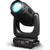
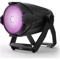
THEATER SPOT WITH 100W WW LED
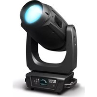
THEATER SPOT WITH 180W WW LED
INSTALLATION/REMOVAL OF BARN DOORS AND
FILTER FRAME 9 DMX TECHNOLOGY 10 TECHNICAL DATA 11
MANUFACTURER’S DECLARATIONS 11-12
CONTROLLO DMX 63 RACCORDI, ELEMENTI DI COMANDO E DI VISUALI- ZZAZIONE3 DMX DEUTSCHFRANCAIS ESPAÑOL ENGLISH ITALIANO POLSKI ENGLISH YOU‘VE MADE THE RIGHT CHOICE! We have designed this product to operate reliably over many years. Please read this User‘s Manual carefully, so that you can begin making optimum use of your Cameo Light product quickly. Learn more about Cameo Light on our website WWW.CAMEOLIGHT.COM. PREVENTIVE MEASURES
1. Please read these instructions carefully.
2. Keep all information and instructions in a safe place.
3. Follow the instructions.
4. Observe all safety warnings. Never remove safety warnings or other information from the equipment.
5. Use the equipment only in the intended manner and for the intended purpose.
6. Use only sufficiently stable and compatible stands and/or mounts (for fixed installations). Make certain that wall mounts are properly installed and secured. Make certain that the equipment is installed securely and cannot fall down.
7. During installation, observ e the applicable safety regulations for your country.
8. Never install and operate the equipment near radiators, heat registers, ovens or other sources of heat. Make certain that the equipment is always installed so that is cooled sufficiently and cannot overheat.
9. Never place sources of ignition, e.g., burning candles, on the equipment.
10. Ventilation slits must not be blocked.
11. This appliance is designed exclusively for indoor use, do not use this equipment in the immediate vicinity of water (does not apply to special outdoor equipment - in this case, observe the special instructions noted below). Do not expose this equipment to flammable materials, fluids or gases. 12. Make certain that dripping or splashed water cannot enter the equipment. Do not place containers filled with liquids, such as vases or drinking vessels, on the equipment.
13. Make certain that objects cannot fall into the device.
14. Use this equipment only with the accessories recommended and intended by the manufacturer.
15. Do not open or modify this equipment.
16. After connecting the equipment, check all cables in order to prevent damage or accidents, e.g., due to tripping hazards. 17. During transport, make certain that the equipment cannot fall down and possibly cause property damage and personal injuries. 18. If your equipment is no longer functioning properly, if fluids or objects have gotten inside the equipment or if it has been damaged in anot her way, switch it off immediately and unplug it from the mains outlet (if it is a powered device). This equipment may only be repaired by authorized, qualified personnel.
19. Clean the equipment using a dry cloth.
20. Comply with all applicable disposal laws in your country. During disposal of packaging, please separate plastic and paper/cardboard.
21. Plastic bags must be kept out of reach of children.
FOR EQUIPMENT THAT CONNECTS TO THE POWER MAINS: 22. CAUTION: If the power cord of the device is equipped with an earthing contact, then it must be connected to an outlet with a protective ground. Never deactivate the protective ground of a power cord. 23. If the equipment has been exposed to strong fluctuations in temperature (for example, after transport), do not switch it on immediately. Moisture and condensation could damage the equipment. Do not switch on the equipment until it has reached room temperature. 24. Before connecting the equipment to the power outlet, first verify that the mains voltage and frequency match the values specified on the equipment. If the equipment has a voltage selection switch, connect the equipment to the power outlet only if the equipment values and the mains power values match. If the included power cord or power adapter does not fit in your wall outlet, contact your electrician. 25. Do not step on the power cord. Make certain that the power cable does not become kinked, especially at the mains outlet and/or power adapter and the equipment connector. 26. When connecting the equipment, make certain that the power cord or power adapter is always freely accessible. Always disconnect the equipment from the power supply if the equipment is not in use or if you want to clean the equipment. Always unplug the power cord and power adapter from the power outlet at the plug or adapter and not by pulling on the cord. Never touch the power cord and power adapter with wet hands. 27. Whenever possible, avoid switching the equipment on and off in quick succession because otherwise this can shorten the useful life of the equipment. 28. IMPORTANT INFORMATION: Replace fuses only with fuses of the same type and rating. If a fuse blows repeatedly, please contact an authorised service centre. 29. To disconnect the equipment from the power mains completely, unplug the power cord or power adapter from the power outlet. 30. If your device is equipped with a Volex power connector, the mating Volex equipment connector must be unlocked before it can be re- moved. However, this also means that the equipment can slide and fall down if the power cable is pulled, which can lead to personal injuries and/or other damage. For this reason, always be careful when laying cables. 31. Unplug the power cord and power adapter from the power outlet if there is a risk of a lightning strike or before extended periods of disuse.
32. The device must only be installed in a voltage-free condition (disconnect the mains plug from the mains).
33. Dust and other debris inside the unit may cause damage. The unit should be regularly serviced or cleaned (no guarantee) depending on ambient conditions (dust etc., nicotine, fog) by qualified personnel to prevent overheating and malfunction.
34. Please keep a distance of at least 0.5 m to any combustible materials.
35. Power cables to power multiple devices must have a cross-section of at least 1.5 mm². Within the EU, the cables must correspond to H05VV-F, or similar. Suitable cables are offered by Adam Hall. With these cables, you can connect multiple devices via the power OUT con- nection to the power IN connection of an additional device. Make sure that the total current consumption of all connected devices does not exceed the specified value on all connected devices (label on the device). Make sure to keep power cable connections as short as possible.4 DMX ITALIANO POLSKI ESPAÑOL FRANCAIS DEUTSCHENGLISH CAUTION: To reduce the risk of electric shock, do not remove cover (or back). There are no user serviceable parts inside. Maintenance and repairs should be exclusively carried out by qualified service personnel. The warning triangle with lightning symbol indicates dangerous uninsulated voltage inside the unit, which may cause an electrical shock. The warning triangle with exclamation mark indicates important operating and maintenance instructions. Warning! This symbol indicates a hot surface. Certain parts of the housing can become hot during operation. After use, wait for a cool-down period of at least 10 minutes before handling or transporting the device. Warning! This device is designed for use below 2000 metres in altitude. Warning! This product is not intended for use in tropical climates. CAUTION! IMPORTANT INFORMATION ABOUT LIGHTING PRODUCTS! 1. The product has been developed for professional use in the field of event technology and is not suitable as household lighting.
2. Do not stare, even temporarily, directly into the light beam.
3. Do not look at the beam directly with optical instruments such as magnifiers.
4. Stroboscope effects may cause epileptic seizures in sensitive people! People with epilepsy should definitely avoid places where strobes are used. INTRODUCTION CONTROL FUNCTIONS 1-channel, 3-channel, 5-channel DMX control Master/Slave operation Standalone functions
1 x high-power 100 W warm white LED. 14-38° beam angle, manual zoom. Adjustable PWM frequency. DMX-512 control. RDM-enabled. Manual control. 16-bit dimming. Master/Slave operation. Operating voltage 100-240 V AC/50-60 Hz. Power consumption 120 W. Mounting bracket, filter frame and barn doors included.
1 x high-power 180 W warm white LED. 14-38 ° beam angle, manual zoom. Adjustable PWM frequency. DMX-512 control. RDM-enabled. Manual control. 16-bit dimming. Master/Slave operation. Operating voltage 100-240 V AC/50-60 Hz. Power consumption 200 W. Mounting bracket, filter frame and barn doors included. The spotlights feature the RDM standard (remote device management). Remote device management allows the user to view status and configuration of RDM terminals via an RDM-capable controller.5 DMX DEUTSCHFRANCAIS ESPAÑOL ENGLISH ITALIANO POLSKI TS 200 WW MENU ENTER
POWER OUT White Power Twist mains socket for the power supply of additional CAMEO spotlights. Ensure that the total current consumption of all connected devices does not exceed the value specified on the device in amperes (A).
FUSE Fuse holder for 5 x 20mm microfuses. IMPORTANT: Replace the fuse only with a fuse of the same type and value (TS100WW: T2A/250V, TS200WW: T3A/250V). In the event of repeated fuse failure, please contact an authorised service centre.
DMX IN Male 3-pin or 5-pin XLR socket for connection to a DMX control device (e.g. DMX console).
DMX OUT Female 3-pin or 5-pin XLR socket for sending the DMX control signal.
ILLUMINATED LC DISPLAY
Displays currently active mode and the menu items in the Edit menu.
CONTROL BUTTONS MENU – Press MENU to access the selection menu for system settings. Press repeatedly to go back to the main display. ENTER – Press ENTER to change a value and to confirm changes. UP and DOWN buttons – Press to move through the individual menu items in the selection menu and submenus (mode, system information, etc.) and to change a value, such as the DMX address.
ZOOM Knurled knob for adjustment of beam size (Fully clockwise = minimum beam size, fully counterclockwise = maximum beam size).
SECURING LUG Overhead installation must only be carried out by qualified personnel. The spotlight must be fitted with a suitable safety rope to ensure that it does not fall down. OPERATION PLEASE NOTE: When the spotlight is connected to the mains, during the startup process, different information will appear in the display: “Update Wait...” (only for service purposes), “WELCOME TO CAMEO”, and the software version. After this process, the spotlight is ready for operation and the previously selected mode will be activated.
MAIN DISPLAY DMX MODE
“DMX Addr” is displayed in the top line of the display and the currently configured DMX start address is displayed in the bottom line. If the DMX signal is interrupted, the display will begin to flash. It will stop flashing once the DMX signal is restored. The main display is activated automatically if no input is made within approximately 30 seconds. DMX Addr
The currently activated standalone mode (slave, static) is shown in the bottom line of the display. The main display is activated automatically if no input is made within approximately 30 seconds. Slave Static7 DMX DEUTSCHFRANCAIS ESPAÑOL ENGLISH ITALIANO POLSKI
DMX MODE CONFIGURATION
Press MENU to access the selection menu for system settings. Using the UP and DOWN controls, select the menu item “Mode” (bottom line) and confirm with ENTER. Using the UP and DOWN buttons, select the submenu item “DMX” and confirm with ENTER. You can now select the desired DMX mode with the UP and DOWN buttons (1CH, 3CH, 5CH) and confirm the selection with ENTER. Press MENU repeatedly to return to the main display. The main display is activated automatically if no input is made within approximately 30 seconds. Tables with the channel assignment of the different DMX modes can be found in these instructions under DMX CONTROL. Menu Mode ENTER UP/DOWN Mode DMX DMX mode 1CH DMX mode 3CH DMX mode 5CH ENTER UP/DOWN / / ENTER
CONFIGURE DMX START ADDRESS
Press MENU to access the selection menu for system settings. Using the UP and DOWN controls, select the menu item “DMX Addr” and confirm with ENTER. You can now configure the DMX start address with the UP and DOWN buttons. Confirm the entry with ENTER and press MENU once to return to the main display. The main display is activated automatically if no input is made within approximately 30 seconds. If the main display is activated, the DMX start address can be changed directly by using the UP and DOWN buttons. Menu DMX Addr ENTER UP/DOWN DMX Addr 001 – 512 ENTER STATIC MODE Press MENU to access the selection menu for system settings. Using the UP and DOWN buttons, select the menu item “Mode” and confirm with ENTER, then use UP and DOWN once again to select the menu item “Static”. Confirm by pressing ENTER twice. You can now use the UP and DOWN buttons to adjust the brightness of the spotlight with values from 000 (blackout) to 255 (maximum brightness). Confirm the entry with ENTER and press MENU repeatedly to return to the main display. The main display is activated automatically if no input is made within approximately 30 seconds. If the main display is activated, the brightness can be adjusted directly by using the UP and DOWN buttons. Menu Mode ENTER UP/DOWN Mode Static ENTER Static Dimmer Dimmer 000-255 ENTER ENTER UP/DOWN SLAVE MODE Press MENU to access the selection menu for system settings. Using the UP and DOWN controls, select the menu item “Mode” (bottom line) and confirm with ENTER. Using the UP and DOWN buttons, select the submenu item “Slave” and confirm with ENTER. Connect the slave and the master units (same model) with a DMX cable and enable the standalone mode static on the master unit. Now the slave unit will follow the master unit. Press MENU repeatedly to return to the main display. The main display is activated automatically if no input is made within approximately 30 seconds. Menu Mode ENTER UP/DOWN Mode Slave ENTER DEVICE SETTINGS Press MENU to access the selection menu for system settings. Using the UP and DOWN controls, select the menu item “Settings” and confirm with ENTER. This will take you to the submenu for setting the submenu items (see table, selection with UP and DOWN, confirm with ENTER). Press MENU repeatedly to return to the main display. The main display is activated automatically if no input is made within approximately 30 seconds.8 DMX ITALIANO POLSKI ESPAÑOL FRANCAIS DEUTSCHENGLISH Settings Display = Display lighting Backlight ON On permanently Backlight Off Deactivates after approximately 30 seconds of inactivity DMX Fail = Operating status with DMX signal fault Hold Last DMX command will be retained Blackout Activates blackout DimCurve = dimmer curve Linear Light intensity increases linearly with DMX value Exp Light intensity can be finely adjusted at lower DMX values and broadly adjusted at higher DMX values. Log Light intensity can be broadly adjusted at lower DMX values and finely adjusted at higher DMX values. S-Curve Light intensity can be finely adjusted at lower and higher DMX values and broadly adjusted at medium DMX values. DimResp. = Dimmer response LED Lamp responds abruptly to changes in DMX value Halogen Lamp behaves like a halogen spotlight with soft brightness changes PWM = LED PWM frequency 650Hz Configuration of LED PWM frequency 1530Hz 3600Hz 25000Hz linear DMX value Light intensity exponential DMX value Light intensity logarithmic DMX value Light intensity S-curve DMX value Light intensity Dimmer curves DEVICE INFORMATION Press MENU to access the selection menu for system settings. Using the UP and DOWN controls, select the menu item "Sys info" and confirm with ENTER. This will take you to the sub-menu for displaying device information. Use the UP and DOWN buttons to select the desired submenu item and then press ENTER to retrieve the information (see table). Press MENU repeatedly to return to the main display. The main display is activated automatically if no input is made within approximately 30 seconds. Sys Info Temp = Displays temperature of LED unit Temp LED xxC / xxF Temp °C/°F °C (= display in degrees Celsius) °F (= display in degrees Fahrenheit) Op.Hours = Operating time display Hour xxxh Displays total operating time in hours Firmware = Displays device software version Soft Ver V1.xx9 DMX DEUTSCHFRANCAIS ESPAÑOL ENGLISH ITALIANO POLSKI
INSTALLATION Thanks to its four rubber feet, the spotlight can be positioned in a suitable location on a level surface. Mounting to a traverse is possible with the pre-installed mounting bracket (A) and a suitable traverse clamp (optional). Ensure firm connections and secure the spotlight to the securing lug (B) with a suitable safety cable. Use the side-mounted lever screws (C) to adjust the vertical beam angle. Important: Overhead mounting requires extensive experience, including the calculation of the load limit values of the installation material and regular safety inspection of all installation materials and spotlights. If you do not have these qualifications, do not attempt to perform an installation yourself. Refer instead to a qualified professional. INSTALLATION/REMOVAL OF BARN DOORS AND FILTER FRAME To install or remove the barn doors and the filter frame please click on the spring-loaded locking pin (D) and fold the bracket upwards. Then return the bracket to its original position so that the locking pin engages.10 DMX ITALIANO POLSKI ESPAÑOL FRANCAIS DEUTSCHENGLISH DMX TECHNOLOGY DMX-512 DMX (Digital Multiplex) is the designation for a universal transmission protocol for communications between corresponding devices and controllers. A DMX controller sends DMX data to the connected DMX device(s). The DMX data is always transmitted as a serial data stream that is forwarded from one connected device to the next via the "DMX IN" and "DMX OUT" connectors (XLR plug-type connectors) that are found on every DMX-capable device, provided the maximum number of devices does not exceed 32 units. The last device in the chain needs to be equipped with a terminator (terminating resistor). DMX CONNECTION DMX is the common "language" via which a very wide range of types and models of equipment from various manufacturers can be connected with one another and controlled via a central controller, provided that all of the devices and the controller are DMX compatible. For optimum data transmission, it is necessary to keep the connecting cables between the individual devices as short as possible. The order in which the devices are integrated in the DMX network has no influence on the addresses. Thus the device with the DMX address 1 can be located at any position in the (serial) DMX chain: at the beginning, at the end or somewhere in the middle. If the DMX address 1 is assigned to a device, the controller "knows" that it should send all data allocated to address 1 to this device regardless of its position in the DMX network.
SERIAL CONNECTION OF MULTIPLE LIGHTS
1. Connect the male XLR connector (3-pin or 5-pin) of the DMX cable to the DMX output (female XLR socket) of the first DMX device (e.g. DMX-Controller). 2. Connect the female 3-pin XLR connector of the DMX cable connected to the first projector to the DMX input (male 3-pin socket) of the next DMX device. In the same way, connect the DMX output of this device to the DMX input of the next device and repeat until all devices have been connected. Please note that as a rule, DMX devices are connected in series and connections cannot be shared without active splitters. The maximum number of DMX devices in a DMX chain should not exceed 32 units. The Adam Hall 3 STAR, 4 STAR, and 5 STAR product ranges include an extensive selection of suitable cables. DMX CABLES When fabricating your own cables, always observe the illustrations on this page. Never connect the shielding of the cable to the ground contact of the plug, and always make certain that the shielding does not come into contact with the housing of the XLR plug. If the shielding is connected to the ground, this can lead to short-circuiting and system malfunctions. Pin Assignment DMX cable with 3-pin XLR connectors: DMX cable with 5-pin XLR connectors (pin 4 and 5 are not used): Shield
Shield DMX TERMINATORS (TERMINATING RESISTORS) To prevent system errors, the last device in a DMX chain needs to be equipped with a terminating resistor (120 ohm, 1/4 Watt). 3-pin XLR connector with a terminating resistor: K3DMXT3 5-pin XLR connector with a terminating resistor: K3DMXT5 Pin Assignment 3-pin XLR connector: 5-pin XLR connector:
DMX ADAPTER The combination of DMX devices with 3-pin connectors and DMX devices with 5-pin connectors in a DMX chain is possible with suitable adapters. Pin Assignment DMX Adapter 5-pin XLR male to 3-pin XLR female: K3DGF0020 Pins 4 and 5 are not used. Pin Assignment DMX Adapter 3-pin XLR male to 5-pin XLR female: K3DHM0020 Pins 4 and 5 are not used.11 DMX DEUTSCHFRANCAIS ESPAÑOL ENGLISH ITALIANO POLSKI TECHNICAL DATA Model number: CLTS100WW CLTS200WW Product type: LED spotlight LED spotlight Type: Fresnel theatre spot with zoom function Fresnel theatre spot with zoom function Colour spectrum: Warm white 3100 K Warm white 3100 K CRI: 97 96 TLCI: 97 97 TM-30-15: R f 91; RG 98 Rf 91; RG 98 Number of LEDs: 1 1 LED type: 100 W 180 W LED PWM frequency: 650 Hz, 1530 Hz, 3600 Hz, 25 kHz (adjustable) 650 Hz, 1530 Hz, 3600 Hz, 25 kHz (adjustable) Beam angle: 14° - 38° 14° - 38° DMX input: Male 3-pin and 5-pin XLR Male 3-pin and 5-pin XLR DMX output: Female 3-pin and 5-pin XLR Female 3-pin and 5-pin XLR DMX mode: 1-channel, 3-channel, 5-channel 1-channel, 3-channel, 5-channel DMX functions: Dimmer, dimmer fine, strobe, dimmer curve, dimmer response Dimmer, dimmer fine, strobe, dimmer curve, dimmer response Control: DMX512, RDM-enabled DMX512, RDM-enabled Standalone functions: Dimmer, Master/Slave Dimmer, Master/Slave Operating controls: Mode, Enter, Up, Down, Zoom Mode, Enter, Up, Down, Zoom Display elements: Illuminated 2-line LCD display Illuminated 2-line LCD display Operating voltage: 100 –240 V AC/50–60 Hz 100 –240 V AC/50–60 Hz Power consumption: 120 W 200 W Light intensity (@ 1m): 52000 lx @ 14° 67500 lx @ 14° Lighting power: 4100 lm 6600 lm Power connection: INPUT: Blue Power Twist socket OUTPUT: White Power Twist socket (Max. 7A) INPUT: Blue Power Twist socket OUTPUT: White Power Twist socket (Max. 6A) Fuse: T2A/250 V (5 x 20 mm) T3A/250 V (5 x 20 mm) Ambient temperature (in operation): 0–40°C 0–40°C Relative air humidity: < 80%, non-condensing < 80%, non-condensing Housing material: Die-cast metal Die-cast metal Housing colour: black black Housing cooling: Temperature-controlled fan Temperature-controlled fan Dimensions (W x H x D, without bracket): 320 x 370 x 310 mm 320 x 370 x 310 mm Weight: 7.4kg 7.5kg Additional features: Filter frame, barn doors and mounting bracket included, manual zoom Filter frame, barn doors and mounting bracket included, manual zoom
MANUFACTURER´S DECLARATIONS
CORRECT DISPOSAL OF THIS PRODUCT
(valid in the European Union and other European countries with a differentiated waste collection system) This symbol on the product, or on its documents indicates that the device may not be treated as household waste. This is to avoid environmental damage or personal injury due to uncontrolled waste disposal. Please dispose of this product separately from other waste and have it recycled to promote sustainable economic activity. Household users should contact either the retailer where they purchased this product, or their local government office, for details on where and how they can recycle this item in an environmentally friendly manner. Business users should contact their supplier and check the terms and conditions of the purchase contract. This product should not be mixed with other commercial waste for disposal.12 DMX ITALIANO POLSKI ESPAÑOL FRANCAIS DEUTSCHENGLISH FCC STATEMENT This device complies with Part 15 of the FCC Rules. Operation is subject to the following two conditions: (1) This device may not cause harmful interference, and (2) This device must accept any interference received, including interference that may cause undesired operation CE Compliance Adam Hall GmbH states that this product meets the following guidelines (where applicable): R&TTE (1999/5/EC) or RED (2014/53/EU) from June 2017 Low voltage directive (2014/35/EU) EMV directive (2014/30/EU) RoHS (2011/65/EU) The complete declaration of conformity can be found at www.adamhall.com. Furthermore, you may also direct your enquiry to info@adamhall.com.13 DMX DEUTSCHFRANCAIS ESPAÑOL ENGLISH ITALIANO POLSKI DEUTSCH SIE HABEN DIE RICHTIGE WAHL GETROFFEN! Dieses Gerät wurde unter hohen Qualitätsanforderungen entwickelt und gefertigt, um viele Jahre einen reibungslosen Betrieb zu gewähr- leisten. Bitte lesen Sie diese Bedienungsanleitung sorgfältig, damit Sie Ihr neues Produkt von Cameo Light schnell und optimal einsetzen können. Weitere Informationen über Cameo Light erhalten Sie auf unserer Website WWW.CAMEOLIGHT.COM. SICHERHEITSHINWEISE